

Page 1
INSTALLATION &
OPERATION MANUAL
GAS INFRARED CHEESE MELTERS
MODEL
ICM24 ML-52470, 52476
ICM36 ML-52471, 52477
ICM48 ML-52472, 52478
ICM60 ML-52473, 52479
ICM72 ML-52474, 52480
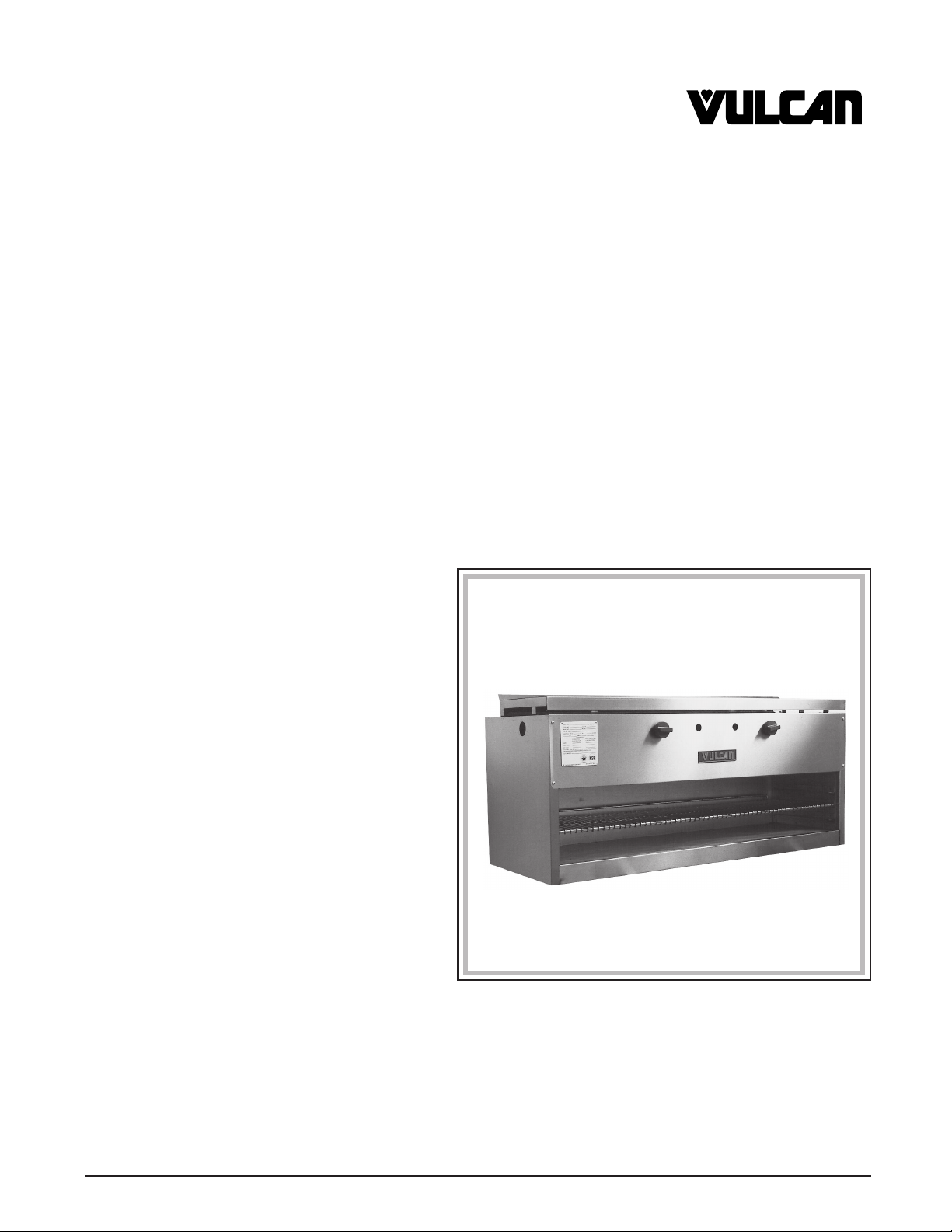
MODEL ICM48
VULCAN-HART COMPANY, P.O. BOX 696, LOUISVILLE, KY 40201-0696, TEL. (502) 778-2791
FORM 30908 (11-94)
Page 2

IMPORTANT FOR YOUR SAFETY
THIS MANUAL HAS BEEN PREPARED FOR PERSONNEL QUALIFIED TO INSTALL GAS
EQUIPMENT, WHO SHOULD PERFORM THE INITIAL FIELD START-UP AND
ADJUSTMENTS OF THE EQUIPMENT COVERED BY THIS MANUAL.
POST IN A PROMINENT LOCATION THE INSTRUCTIONS TO BE FOLLOWED IN THE
EVENT THE SMELL OF GAS IS DETECTED. THIS INFORMATION CAN BE OBTAINED
FROM THE LOCAL GAS SUPPLIER.
IMPORTANT
IN THE EVENT A GAS ODOR IS DETECTED, SHUT DOWN
UNITS AT MAIN SHUTOFF VALVE AND CONTACT THE
LOCAL GAS COMPANY OR GAS SUPPLIER FOR
SERVICE.
FOR YOUR SAFETY
DO NOT STORE OR USE GASOLINE OR OTHER
FLAMMABLE VAPORS OR LIQUIDS IN THE VICINITY OF
THIS OR ANY OTHER APPLIANCE.
WARNING: IMPROPER INSTALLATION, ADJUSTMENT,
ALTERATION OR MODIFICATION, SERVICE OR
MAINTENANCE CAN CAUSE PROPERTY DAMAGE,
INJURY OR DEATH. READ THE INSTALLATION,
OPERATING AND MAINTENANCE INSTRUCTIONS
THOROUGHLY BEFORE INSTALLING OR SERVICING
THIS EQUIPMENT.
IN THE EVENT OF A POWER FAILURE, DO NOT
ATTEMPT TO OPERATE THIS DEVICE.
– 2 –
Page 3
Installation, Operation, and Care of
MODELS ICM24, ICM36, ICM48, ICM60 & ICM72
GAS INFRARED CHEESE MELTERS
KEEP THIS MANUAL FOR FUTURE USE
GENERAL
The Vulcan Gas Infrared Cheese Melters use efficient gas heat and are available in 24, 36, 48, 60, or
72 inch widths. Each model has one or two burners; each burner has its own pilot light and control knob.
GAS RATINGS
Model ICM24 ICM36 ICM48 ICM60 ICM72
BTU Rating 20,000 BTU/hr 30,000 BTU/hr 40,000 BTU/hr 50,000 BTU/hr 60,000 BTU/hr
INSTALLATION
UNPACKING
Immediately after unpacking, check for possible shipping damage. If the Cheese Melter is found to be
damaged, save the packaging material and contact the carrier within 15 days of delivery.
Before installing, verify that the gas (natural or propane) agrees with the specifications on the rating
plate located on the front.
LOCATION
The area around the appliance must be kept free and clear from combustibles. The area in front of and
above the Cheese Melter must be clear to avoid any obstruction to the flow of combustion and
ventilation air. Means must be provided for adequate air supply and adequate clearance for air
openings into the combustion chamber.
Adequate clearance must be provided in front and at the sides of the appliance for servicing and proper
operation.
The Cheese Melter can be installed in combustible or noncombustible locations. Clearance from
combustible construction must be a minimum of 6 inches from the sides and 0 inches from the back.
There are no minimum clearances from noncombustible construction.
The Cheese Melter can be installed on a noncombustible counter, with or without 4" legs, or mounted
on a combustible or noncombustible wall: Leg kits and wall mounting brackets are available from your
Vulcan-Authorized Service Office for your model Cheese Melter. If installing the Cheese Melter on a
combustible counter, the 4" legs are required.
– 3 –
Page 4

ASSEMBLY — Legs (optional)
If using legs, four legs are required on 24, 36, and 48" models; six legs are required on 60 and 72"
models. Assemble legs to the bottom of the unit through threaded holes in the four corners of the unit;
on 60 and 72" models, the extra two legs mount at the middle of the front and back rails.
ASSEMBLY — Wall Mounting Brackets (optional)
If mounting the Cheese Melter on a wall: Attach the wall mounting bracket(s) to the wall with suitable
fasteners (not supplied with the kit); hang the Cheese Melter from its angle iron rail on the wall mounting
bracket(s) (Fig. 1).
Angle Iron on Rear of
Cheese Melter Frame
Wall Mounting Brackets
Fig. 1
INSTALLATION CODES AND STANDARDS
In the United States, the Cheese Melter must be installed in accordance with: 1) State and local codes;
2) National Fuel Gas Code, ANSI-Z223.1, latest edition, available from American Gas Association,
1515 Wilson Boulevard, Arlington, VA 22209; and 3) NFPA Standard #96,
Cooking Equipment
, latest edition, available from the National Fire Protection Association, Batterymarch
Vapor Removal from
Park, Quincy, MA 02269.
In Canada, the Cheese Melter must be installed in accordance with: 1) Local codes, or in the absence
of local codes, with Canadian Standard CAN/CGA-B149.1 NATURAL GAS, latest edition, or
CAN/CGA-B149.2 PROPANE GAS, latest edition, available from Canadian Gas Association, 55
Scarsdale Road, Don Mills, Ontario, Canada M3B2R3.
– 4 –
Page 5

GAS CONNECTION
Caution: The pipe thread compound used when installing pipes must be a type that is resistant
to the action of liquified petroleum or propane gases.
Codes require that a manual gas valve be installed in the gas supply line ahead of the appliance. Make
sure the pipes are clean and free of obstructions, dirt, and piping compound. A pressure regulator is
supplied loose with the Cheese Melter for installation in the gas supply line. The Natural gas regulator
requires a pressure of 5" Water Column. The Propane gas regulator requires a pressure of 10" Water
Column. The arrow on the rear of the pressure regulator indicates the direction of gas flow. The
regulator (Fig. 2) must be installed so the arrow points down. If it is installed so the arrow is not pointing
down, the pressure must be reset. Connect the Cheese Melter to the gas supply with a
or larger. If a flexible connector is used, it must be
3
/4" I.D. A 1/8" pressure tap is located on the manifold
3
/4" iron pipe
for checking the gas pressure. Natural or Propane gas conversion and orifice changes for various
altitudes can be performed by Vulcan-authorized servicers.
WARNING: PRIOR TO START-UP, CHECK ALL JOINTS IN THE GAS SUPPLY LINE FOR LEAKS.
USE SOAP AND WATER SOLUTION. DO NOT USE AN OPEN FLAME.
TESTING THE GAS SUPPLY PIPING
When test pressures exceed
1
/2 psig (3.45 kPa) the Cheese Melter and its individual shut-off valve must
be disconnected from the gas supply piping system during any pressure testing of the system. When
test pressures are
1
/2 psig (3.45 kPa) or less, the Cheese Melter must be isolated from the gas supply
piping system by closing its individual shut-off valve during any pressure testing of the system.
EXHAUST FAN
A mechanical exhaust hood must be installed above the appliance; the exhaust blower must have a
capacity of 200 CFM per square foot of broiler area, check local code for specific requirements.
Model ICM24 ICM36 ICM48 ICM60 ICM72
Minimum Exhaust Fan Rating 388 CFM 604 CFM 821 CFM 1038 CFM 1255 CFM
LIGHTING THE GAS PILOT TUBE(S)
Before lighting the Cheese Melter, make sure that all burners are turned off. Wait 5 minutes. Turn on
the manual gas valve and use a taper to light the gas pilot tube(s). A gas pilot tube is located below
each burner (Fig. 3).
Pressure Regulator
PL-40507-1
Pilot Tube
Fig. 2 Fig. 3
– 5 –
Lighted Taper
PL-40508-1
Page 6

OPERATION
WARNING: THE CHEESE MELTER AND ITS PARTS ARE HOT. USE CARE WHEN OPERATING,
CLEANING, AND SERVICING THE CHEESE MELTER.
CONTROLS (Fig. 4)
Burner Valve — Turn fully ON or OFF by rotating the control knob 1/4 turn.
Pilot Adjustment Screw
OFF
ON
Fig. 4
Burner Valve
The Cheese Melter rack can be positioned in one of the three operating levels.
Complete Shut Down
For complete shut-down: Turn the Burner Valve(s) off. Shut the manual gas valve off and the pilot
tubes will go out.
CLEANING
Cheese Melter must be cool before cleaning. Cheese Melter rack should be cleaned daily by washing
in hot water and detergent. Use non-abrasive type cleaning pads to remove burned on particles. After
washing, rinse with hot water.
Aluminized Steel Interior — clean with mild detergent (or soap) and water solution. Heavy soil can
be loosened with a wooden tool or use a non-etching cleaner recommended for aluminized steel. DO
NOT use steel wool, wire brush, or caustic solutions such as lye, soda ash, or ammonia. Rinse with
clear water and dry with a soft cloth.
Stainless Steel Interior — for routine cleaning use detergent (or soap) and water solution. Burned-
on foods and grease can be removed with an abrasive cleanser (scouring powder) mixed into a paste.
Apply with stainless steel wool — always rub with the grain. Rinse with clear water; dry with a soft cloth.
Vent System — At least once a year the exhaust hood (venting system) should be examined and
cleaned.
SERVICE
Contact your local Vulcan-authorized service office for repairs or adjustments needed on this
equipment.
– 6 –
Page 7

– 7 –
Page 8

FORM 30908 (11-94) PRINTED IN U.S.A.
– 8 –
 Loading...