

Page 1
FORM 30011 (2/90)
INSTALLATION, OPERATING, SERVICE
AND PARTS MANUAL FOR
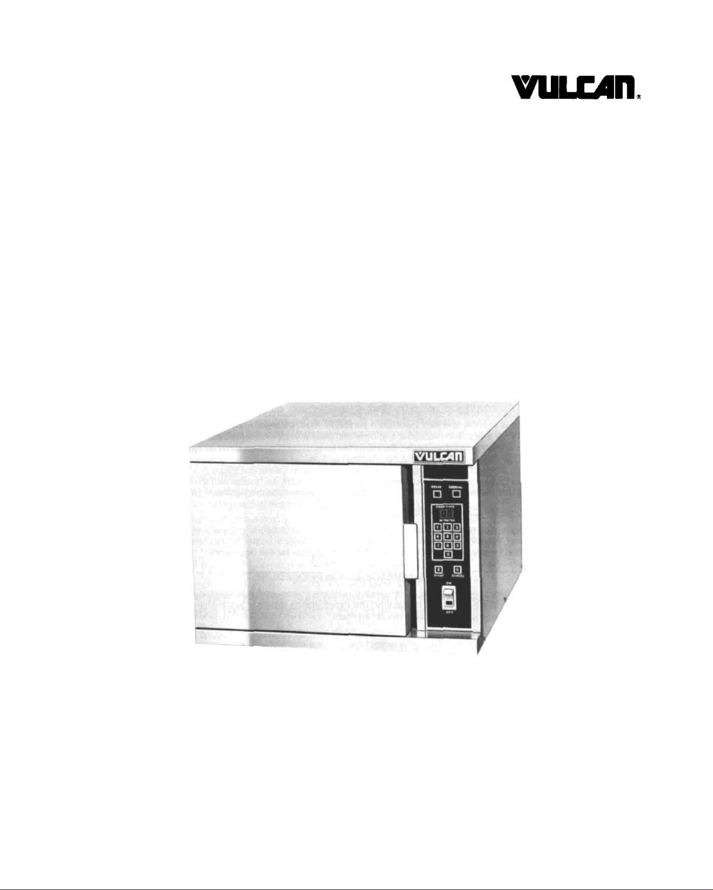
ELECTRIC COUNTER CONVECTION
STEAMER MODEL VSXII
Vulcan service agencies are located throughout the United States. For location
and phone number of one near you, call your local Vulcan dealer.
VULCAN-HART CORPORATION, P.O. BOX 696, LOUISVILLE, KY 40201-0696, TEL. (502) 778-2791
Page 2

IMPORTANT
OPERATING, INSTALLING AND SERVICE PERSONNEL
The operating information on this equipment has been prepared for use by qualified and/or
authorized operating personnel.
All installation and service on this equipment is to be performed by qualified, certified, licensed
and/ or authorized installation or service personnel, with the exception of any part marked with
a in front of the part number.
To obtain the name and location of an authorized Vulcan service agency, contact your Food
Service Equipment dealer.
DEFINITIONS
QUALIFIED AND/OR AUTHORIZED OPERATING PERSONNEL
Qualified or authorized operating personnel are those who have carefully read the information in
this manual and are familiar with the equipment's functions or have had previous experience with
the operation of the equipment covered in this manual.
1. For the installation of gas piping from the outlet side of the gas meter, or the service regulator
when the meter is not provided, and the connection and installation of the gas appliance,
qualified installation personnel must be experienced in such work, be familiar with all
precautions required, and have complied with all requirements of state or local authorities
having jurisdiction. In the absence of local codes, installation must comply with National Fuel
Gas Code ANSI Z223.1 -latest edition.
2. For the installation of electrical wiring from the electric meter, main control box or service outlet
to the electric appliance, qualified installation personnel must be experienc ed in such work, be
familiar with all precautions required, and have complied with all requirements of state or local
authorities having jurisdiction. In the absence of local codes, installation must comply with the
National Electrical Code ANSI NFPA No. 70 latest edition.
3. For the installation of steam piping from the source of supply to the service inlet of the
appliance, qualified installation personnel must be experienced in such work, be familiar with all
precautions required, and have complied with all requirements of state or local authorities
having jurisdiction.
QUALIFIED SERVICE PERSONNEL
Qualified service personnel are those who are familiar with this equipment who have been
endorsed by our company. All authorized service personnel are required to be equipped with a
complete set of service and parts manuals and stock a minimum amount of parts for this
equipment.
SHIPPING DAMAGE CLAIM PROCEDURE
For your protection, please note that equipment in this shipment was carefully inspected and
packed by skilled personnel before leaving the factory. The transportation company assumes full
responsibility for safe delivery upon acceptance of this shipment.
If shipment arrives damaged:
1. VISIBLE LOSS OR DAMAGE — Be certain this is noted on freight bill or ex press receipt
and signed by person making delivery.
2. FILE CLAIM FOR DAMAGES IMMEDIATELY — Regardless of extent of damage.
3. CONCEALED LOSS OR DAMAGE — If damage is unnoticed until merchandise is
unpacked, notify transportation company or carrier immediately, and file "concealed damage"
claim with them. This must be done within fifteen (15) days of the date the delivery is made to
you. Be sure to retain container for inspection.
We cannot assume responsibility for damage or loss incurred in transit. We will, however, be glad
to furnish you with necessary documents to support your claim.
PLEASE RETAIN THIS MANUAL FOR FUTURE REFERENCE
Page 3

IMPORTANT NOTES FOR ALL VULCAN APPLIANCES
1. These units are produced with the best possible workmanship and material. Proper installation is vital if best
performance and appearance are to be achieved. Installer must follow the installation instructions carefully.
2. Information on the construction and installation of ventilating hoods may be obtained from the "Standard for the
installation of equipment for the removal of smoke and grease laden vapors from commercial cooking
equipment," NFPA No. 96 (latest edition) available from the National Fire Protection Association, Battery March
Park, Quincy MA 02269.
3. For an appliance equipped with a flexible electric supply cord, the cord is equipped with a three prong
(grounding) plug. This grounding plug is for your protection against shock hazard and should be plugged
directly into a properly grounded three prong receptacle. Do not cut or remove the grounding prong from this
plug. If the appliance is not equipped with a grounding plug, and electric supply is needed, ground the
appliance by using the ground lug provided (refer to the wiring diagram).
(FOR GAS APPLIANCES ONLY)
4. Do not obstruct the air flow into and around the appliance. This air flow is necessary for proper combustion of
gases and for ventilation of the appliance. Provisions for ventilation of incoming air supply for the equipment in
the room must be in accordance with National Fuel Gas Code ANSI Z223.1 (latest edition).
5. Do not obstruct the flow of flue gases from the flue duct (when so equipped) located on the rear (or sides) of
the appliance. It is recommended that the flue gases be ventilated to the outside of the building through a
ventilation system installed by qualified personnel.
6. For an appliance equipped with casters, (1) the installation shall be made with a connector that complies with
the Standard for Connectors for Movable Gas Appliances, ANSI Z21.69 (latest edition), and Addenda, Z21.69a
(latest edition), and a quick-disconnect device that complies with the Standard for Quick-Disconnect Devices
for Use With Gas Fuel, ANSI Z21.41 (latest edition), and Addenda, Z21.41 a (latest edition), and Z21.41 b
(latest edition), and (2) adequate means must be provided to limit the movement of the appliance without
depending on the connector and the quick-disconnect device or its associated piping to limit the appliance
movement.
If disconnection of the restraint is necessary, reconnect this restraint after the appliance has been returned to
its originally installed position.
7. The appliance and its individual shutoff valve must be disconnected from the gas supply piping system during
any pressure testing of that system at test pressures in excess of 1/2 psig (3.45 k Pa).
8. The appliance must be isolated from the gas supply system by closing its individual manual shutoff valve
during any pressure testing of the gas supply system at test pressures equal to or less than 1/2 psig (3.45 k
Pa).
CAUTIONS
FOR YOUR SAFETY
DO NOT STORE OR USE GASOLINE OR OTHER FLAMMABLE VAPORS
AND LIQUIDS IN THE VICINITY OF THIS EQUIPMENT OR ANY OTHER
APPLIANCE.
1. KEEP THE APPLIANCE FREE AND CLEAR FROM ALL COMBUSTIBLE SUBSTANCES.
2. IN THE EVENT A GAS ODOR IS DETECTED, SHUT UNIT(S) DOWN AT THE MAIN
SHUTOFF VALVE AND CONTACT THE LOCAL GAS COMPANY OR GAS SUPPLIER
FOR SERVICE.
3. POST IN A PROMINENT LOCATION, INSTRUCTIONS TO BE FOLLOWED IN THE
EVENT THE SMELL OF GAS IS DETECTED. THIS INFORMATION MAY BE OBTAINED
FROM A LOCAL GAS SUPPLIER.
3
Page 4

ELECTRIC COUNTER CONVECTION STEAMER
MODEL: VSXII
INSTALLATION, OPERATING, SERVICE
AND PARTS MANUAL INDEX
Your Vulcan Counter Steamer is produced with quality
workmanship and material. Proper installation, usage
and maintenance will result in many years of
satisfactory performance.
The manufacturer suggests that you thoroughly read
this entire manual and carefully follow all of the instruc -
DESCRIPTION PAGE
DEFINITIONS OF PERSONNEL (Operating, Installation and Service) and
SHIPPING DAMAGE CLAIM PROCEDURE
IMPORTANT NOTES 3
INDEX 4
WATER CONDITIONING 5
DESCRIPTION 5
tions provided. Please retain this manual for future
reference.
A data plate with the unit model number and serial
number, electrical characteristics, etc., is on the lower
left front corner of the body side panel.
(Inside Front Cover)
ELECTRICAL CHARACTERISTICS 6
INSTALLATION 7
SERVICE CONNECTIONS 7
START -UP 8
OPERATING 8
CLEANING 9
COOKING CHART 10-12
SERVICE 13-14
PARTS LIST 15-20
WIRING DIAGRAM 21-23
RECOMMENDED SPARE PARTS LIST 24
4
Page 5

WATER CONDITIONING
It is important to furnish the steam generator with soft
water to minimize scale formation, which will reduce
steam output, cause premature component failure,
and shorten equipment life. Most water supplies
contain scale producing minerals. As steam is
produced by the steam generator, the minerals
remain and dissolve into the water. As the
concentration of these minerals increases past a
certain point, they precipitate from the water and coat
the surfaces inside the generator, the heating
elements, the steam generator interior surfaces, and
water level control probes. Because of the high
temperature of these surfaces, the precipitated
minerals bake onto them and become very difficult to
remove.
This phenomenon causes several problems.
1. The surfaces of the heating devices will become
coated with scale, reducing the heat transfer effi ciency. On electric heating elements, the scale will
produce hot spots on the elements and cause
premature failure of the elements.
2. Water level probes are used in all steam
generators, and these too will become coated with
scale. In this case, scale will bridge across the
probe insulator from the metal extension, which
senses the water level, to the boiler shell. Once
the scale is wet, it can prevent the water level
control from maintaining the proper water level in
the boiler shell. This situation may cause an electric
heating element to fail as a result of the element not
being adequately covered by water.
All of these problems are common to any
manufacturer's steamer regardless of design, but they
can all be prevented by furnishing the steam
generator with soft water. Vulcan-Hart recommends
the water contain no more than 2.0 grains of hardness
(TDS) and have a pH of 7.5. This degree of hardness
can be easily and inexpensively achieved by the use
of a properly maintained water softener. The use of a
water meter will determine the water consumption and
when the water softener needs regeneration or
recharging.
NOTE: The use of strainers, or filters will not remove
minerals from the water.
Steamers which have been operated for a period of
time without the benefit of a water softener, and which
have developed a heavy scale build up should be
cleaned prior to the use of a water softener. Our
recommended method used for removing scale is
"Descaling" on page 14.
DESCRIPTION
This Vulcan self generating electric counter
convection steamer is manufactured with a 7.5 KW
electric input. This steamer generates steam in a
stainless steel pressureless steam generator located
behind the steaming compartment. The sheathed
electric elements are mounted inside the steam
generator. When the "red" (ON-OFF) operating switch
is turned ON the generator automatically fills with
water to a preset level. The electric elements are
automatically turned ON allowing the water to be
heated to a high temperature ready condition (door
open or closed). The probes automatically measure
the water level allowing the water to fill the
generator to the proper level and automatically
maintain the water level necessary for proper
operation.
Place full sized 12" x 20" (or half sized) pans in the
compartment. Close the door. Press the minutes to
cook button(s). Press the start button to begin
cooking. When the end of cooking buzzer sounds,
open the door and remove the cooked food. The
buzzer shuts off. When through cooking for the day,
turn the power switch off and the "blown down" cycle
automatically begins using the remaining steam to
"blow out" the water and loose scale in the generator
to the drain.
5
Page 6
ELECTRICAL CHARACTERISTICS
4
9
2
208V 230V 240V
Model
VSXII
Model
PH KW AMP KW AMP KW AMP
1 7.5 36.1 7.5 32.6 7.5 31.3
VSXII
3 7.5 20.8 7.5 18.9 7.5 18.1
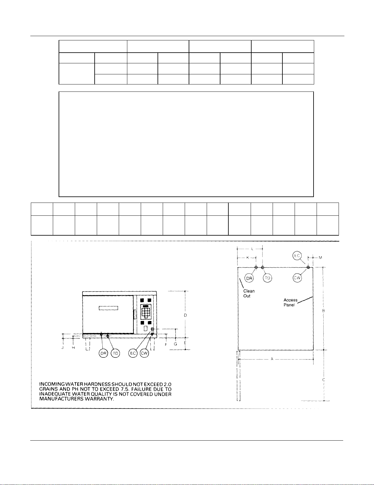
SERVICE CONNECTIONS
CW Cold Water: 3/8" (9.5mm) tubing to
condensor at min 25 to max 50
PSI.
DR Drain: 1" (25 mm) IPS piped to
open floor drain. No solid connection.
Must be open air gap with a maximum
24" length before the open air gap
opening (no bends or elbows in 24").
Total length maximum 6' with only one
elbow.
inches
mm
A B C D E F G H J K L M
24
610
27 1/2
699
18
457
15 1/8
384
102
TD Trough Drain: Interconnected
to main drain (DR).
EC Electric Connection: 1 1/ 2" (38mm)
conduit connection to
electrical box.
1 1/2
38
4 7/8
124
1 1/4
32
1 1/2
38
229
10
254
51
6
Page 7
INSTALLATION
WARNING: Electrical and ground
connections must comply with the applicable
portions of the National Electrical Code
and/or other local electrical codes.
WARNING: Plumbing connections must
comply with applicable health, safety and
plumbing codes.
The Vulcan VSXII is a single compartment
pressureless steam cooker that has been factory
assembled and tested. The unit has been crated to
protect it during transportation.
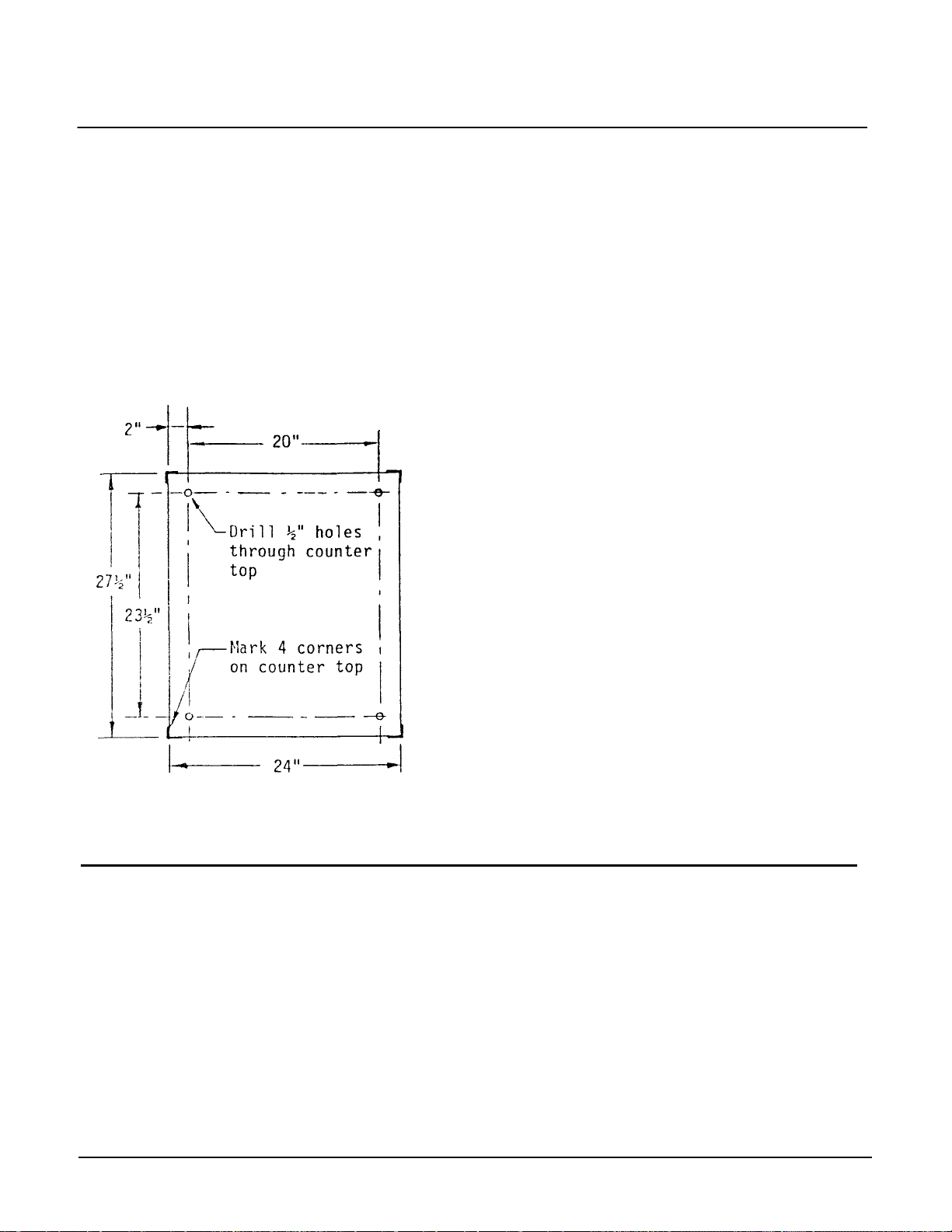
A. Remove the counter steamer from the carton.
B. It is a free standing unit not to be enclosed. Place
the unit in the desired position on a level counter
top. Then mark the 4 corners. Check that there
are suffi cient clearances to service the controls,
for door swing, etc., so that there will be no
problem in making the required supply
connections. Minimum clearances are 2" on the
sides and 6" on the back for proper air circulation
through the louvers on the sides and the rear of
the unit, and 6" away from any open heat. A 36"
minimum clearance is required at the front for
adequate access to the cooking compart ment.
Next, set the unit aside to drill four 1/2" holes.
C. Drill 1/2" holes as indicated in the drawing.
D. Apply a bead of high grade sealant around the
bottom outside edge of this unit. Failure to comply
with this requirement will void the N.S.F. label.
E. Set the unit back on the counter and bolt it down
securely with 3/8-l 6 bolts.
When ordered as an option, the Vulcan counter
steamer will have 4 adjustable 4" legs packed in
the carton. Screw the legs securely into the
bottom corner of the unit. Set the unit on the
counter top. Use the levelers supplied with the 4"
legs to level the unit using a spirit level. Level left
to right and front to back. Steamers should be
elevated in the front just enough (approximately
1/16" to 1/8" ) to give proper drainage. (Check
level by pouring a little water in the compartment.
All of the water should drain).
SERVICE CONNECTIONS___________________________________
The Vulcan counter steamer is a self-contained unit
with field replaceable elements rated at 7.5 KW.
A. Water Connection: the unit has a 3/8" copper tube
input to which the water supply line has to be connected.
The 3/8" copper tube supplies water to both the
generator tank and to the cold water condenser
which condenses the steam entering the drain
line. A manual shut off valve (supplied by others)
must be provided convenient to the unit to use
when removing scale.
B. Electrical Connection: The voltage and phase sup
plied at the installation point must be the same as
indicated on data plate. The supply wiring and
circuit protection must be adequate for the
kilowatt load drawn by the unit. Use copper wire
suitable for at least 200°F. (90°C.). The unit must
be grounded.
C. Drain Connection: Use with an open gap drain.
Must be 1" IPS vertically down and preferably with
only one elbow and a maximum of 6 feet in
length, piped to an open floor drain. A solid
connection will result in back pressure to the
compartment and overflow the drain trough.
7
Page 8

START UP
WARNING: The cooking compartment
contains hot steam. To avoid burns, stay
clear of the door when opening it.
When the unit has been installed and all service
connections have been made, the steamer should be
checked out before operating.
A. Turn the power switch on the control panel to
"ON". The COOK TIME-MINUTES "Window" will
display "00".
B. Touch number 8 on digital control panel twice.
Note that two complete 8's (all segments of the 8)
in the display window light up. Next, touch all the
other numbers and check that they also light up
completely
C. Touch CANCEL and the display window will show
"00".
D. 15 minutes after turning on the power switch, the
READY (green) light will come on, indicating that
the steamer is ready for the cooking cycle. Open
the door and check that no steam has entered the
cooking compartment.
E. Close the door and touch number 2 and "02" will be
displayed. This indicates that the unit is set for two
minutes of cooking time.
F. Touch START. The READY light will go off and
the COOK (red) light will come on and steam will
be heard entering the cooking compartment.
Inspect that the cold water condenser is operating
and is evident by observing water entering the
open drain.
G. After one minute when the display window shows
"01", open the door and observe for two or three
minutes that the steam has stopped entering the
cooking compartment, while the COOK light and
cooking time at "01" are still showing.
H. Shut the door. Steam generation and the cook
time will start again. When the display window
shows "00", the buzzer will start, steam generation
will stop, the COOK light will go off and the
READY light will come on.
I. To stop the buzzer, open the door and the food
should be removed.
J. Turn the power switch to OFF. The drain solenoid
valve will open and the steam generator will "blow
down". Check the open drain and note that hot
water is being drained.
OPERATING
WARNING: The cooking compartment
contains hot steam. To avoid burns, stay
clear of the door when opening it.
A. Prepare for cooking by turning the power switch
"ON" The cook time minutes "Window" will display
"00" and the generator tank will automatically fill
with water and be brought up to the READY
temperature with the heater elements, in about 15
minutes.
B. When the READY light (green) comes on, preheat
the cooking compartment for one minute by
pressing number 1 on digital panel and then press
START. The READY light will go off and the
COOK light (red) will come on. Be certain that the
door is closed. Steps A and B are only required
when the cooking compart ment is cold or when
the unit is to be used the first time during the day.
When the buzzer sounds, open and then close the
door to silence it.
C. Your unit is now ready for cooking.
D. With compartment preheated and the READY light
on place pans of food into cooking compartment
and shut the door. Refer to the cooking guide
located after the cleaning section.
E. Press cooking minutes on the digital panel, then
touch START for the cooking cycle to begin. The
cooking cycle may be interrupted at any time by
opening the door and it can be started again by
closing the door.
F. When the buzzer sounds, it indicates the end of
the cooking cycle and no more steam will be
entering the cooking compartment. The buzzer is
silenced by opening the door and removing the
cooked food. The COOK light will go off and the
READY light will come on.
G. Touching CANCEL will automatically display "00"
on "Window". The correct minute time can now be
entered and the next item to be cooking can begin
its cycle.
H. To shut down your steamer, turn the power switch
to OFF and the generator tank will automatically
blow down, removing water and loose scale.
8
Page 9

PAN CAPACITY
Each steamer compartment will hold combinations of
the following pan sizes (either solid or perforated):
PAN SIZE MAXIMUM QUANTITY DEPTH OF PAN
12X20 1 6"
12x20 2 4"
12X20 3 2-1/2"
12x20 6 1"
CLEANING
Remove any pans and oven racks from the compart ment and wash them in the sink. Wash the
compartment interior with clean water. Never use
steel wool or abrasive scouring pads as they will
scratch and ruin the general surface appearance of
your appliance. Use a clean damp cloth to wipe down
the exterior.
CAUTION: NEVER SPRAY WATER ON TO
THE ELECTRIC CONTROLS.
9
Page 10

COOKING CHART
Long grain
regular/vermicelli
shells/elbows
wide
15
18
15
Ground chuck
25
Pounds
Beans
9
Can
THE FOLLOWING ITEMS MUST BE COOKED IN SOLID PANS:
FOOD
TIMER SETTING
IN MINUTES
Eggs - Scrambled 10- 12 8 Dozen
Rice (Add 4 cups water/Ib)
Pasta (Place a perforated pan inside a solid pan, cover pasta with cold water)
-Spaghetti -
-Macaroni -
-Noodles -1/2"
-Lasagna noodles
Frozen casseroles, lasagna 35 Full pan
Meat Loaf (3 - 5 Ibs each) 40 15 Pounds
Beef -
-Sliced as purchased
Shrimp, frozen
(10 shrimps per Ib)
25 2 Pounds
12151215-18
2035-40
5
FOOD WEIGHT
PER PAN
10
10 Pounds
4 Pounds
-Baked
-Refried
Canned vegetables 6 10 Pound Opened Can
Prunes, dried 12- 15
9
10 Pound Opened
10 Pound Opened Can
10
Page 11

COOKING CHART (Cont.)
PERFORATED PANS ARE RECOMMENDED FOR FOLLOWING ITEMS:
ITEM
Clams
-Frozen 10- 12 3 Dozen
-Fresh, cherrystone 5-6 3 Dozen
King Crab (frozen)
-Claws 4 2 1/2 Pounds
-Legs 4-6 4 1/2 Pounds
Lobster tail (frozen) 6 10 Pounds
Lobster live (10"-12") 5 4 Per Pan
Salmon fillets (frozen - 8 oz. ea.) 5 7 1/2 Pounds
Scallops (fresh) 4 3 Pounds
Scrod fillets (fresh) 3-5 4 Pounds
Eggs
-Hard Cooked 15 4 Dozen
-Soft Cooked 9-10 4 Dozen
-Soft yoke for Caesar Salad 6-8 4 Dozen
Chicken
-Breasts, legs, thighs 20 15 Pounds
Turkey (frozen)
-Breasts (2) 90 6-7 Pounds each
-Cut lengthwise 55 20-25 Pounds
Corned Beef 40-75 6-8 Pounds
Hot dogs or wieners 3 80-100 Count
Asparagus spears
-Frozen 10- 12 3 Dozen
-Fresh 5 5 Pounds
Beans
-Green - 2" cut (frozen/fresh) 6 5 Pounds
-Lima (frozen) 8 5 Pounds
-Baby lima (frozen) 5 5 Pounds
Broccoli
-Spears (frozen) 8 4 Pounds
-Spears (fresh) 6 5 Pounds
-Flowerettes (froz en) 6 5 Pounds
TIMER SETTING
IN MINUTES
WEIGHT
PER PAN
11
Page 12

COOKING CHART (Cont.)
TIMER SETTING
WEIGHT
PERFORATED PANS RECOMMENDED FOR FOLLOWING ITEMS: (Continued)
ITEM
Brussel sprouts (frozen) 6 5 Pounds
Cabbage (fresh) 1/6 cut 8 5 Pounds
Carrots
-Baby whole (frozen) 8 7 Pounds
-Crinkle cut (frozen) 7-8 4 Pounds
-Sliced (fresh) 11 9 Pounds
Cauliflower, flowerettes
-Frozen 6 4 Pounds
-Fresh 7-8 5 Pounds
Celery (1" diagonal cut) 7 5 Pounds
Corn
-Yellow whole kernel (frozen) 5 5 Pounds
-Cobbettes (frozen) 8 27 Ears
-Corn-On-Cob (fresh) 10-12 18 Ears
Peas,green 6 5 Pounds
Potatoes, whole russet 55 40 Pounds
Spinach
-Chopped (frozen) 17 6 Pounds
-Defrosted 5 6 Pounds
-Fresh cut 3 2 Pounds
Squash-Acorn Halves 25 10 halves
Zucchini, slices 8 10 Pounds
Frozen mixed vegetables 6-7 5 Pounds
Fruit-Blanch for peeling:
-Grapefruit 3
-Oranges
Pineapple - whole for cutting 4
INMINUTES
16- 18 80 Ears
16-18 54 Ears
PER PAN
12
Page 13

SERVICE
WARNING: Disconnect the electrical power to
the machine at the disconnect switch. Place a
tag on the disconnect switch indicating the
circuit is being worked on.
WARNING: Certain procedures in this section
require electrical tests or measuremen ts
while power is applied to the machine.
Exercise extreme caution at all times. If test
points are not easily accessible, disconnect
power, attach test equipment and reap-ply
power to test.
HIGH ALTITUDE LOCATIONS
The Vulcan counter steamer has been factory set
when ON to maintain water temperature during the
READY phase in the steam generator tank at
approximately 205 deg.F. (just below water boiling
point). However, for high altitude locations a qualified
service person must adjust this temperature using the
following procedure:
A. Remove the side panel and turn the control panel
power switch to ON.
B. Open the compartment door. After about 15
minutes steam will be seen entering the cooking
department.
C. On the large printed circuit board, use a
screwdriver to turn the "TEMP" dial slowly
counter-clockwise to lower the temperature until
steam just ceases to enter cooking compartment
and the READY light goes on.
D. Replace the side panel.
E. Follow Start Up Instructions - Page No. 7.
WATER FLOWING INTO THE DRAIN
DURING SHUT DOWN
When the unit is shut down and yet cold water is
running continuously into open drain, it indicates
that either or both solenoid valves did not close
when de-energized. Solenoid valve(s) must be
disassembled and examined for scalant or foreign
particles lodging in the diaphram or the core tube.
Clean valve(s) thoroughly and reas semble or
replace the valve(s).
WATER OVERFLOWS INTO THE COOKING
COMPARTMENT
When the unit is first turned on for the day -and the
READY light does not come on after about 15
minutes of operating time and water begins to
overflow into the cooking compartment and the
water fill solenoid valve is open
any or all of the above symptoms may indicate that the
failure of the operating probe to function is due to
either:
A. A "short" between the operating probe terminal
and the terminal on large printed circuit board
marked "OP" - or
B. Excessive scale has built up on the operating
probe. This acts as "insulation" and prevents the
probe from sensing the water level and, therefore,
it is unable to de-energize the water fill (solenoid)
valve to shut the water off.
As a temporary solution, with power off, probes
should be unscrewed, checked visually and
scalant cleaned or chipped off and then replace
the probe. This is an indication of severe harmful
water conditions and should be corrected
immediately to avoid damage to the components
and the ultimate malfunction of your unit.
COOKING CYCLE DOES NOT OPERATE
NOTE: Tests should be performed by a qualified
service technician.
Check that the READY (green) light is on. A glass
encased switch, magnetically activated, is located inside and directly behind the front enclosure (above the
striker) indirect alignment with a magnet in the door.
When the door is opened, this switch automatically
opens and will place the cooking time on hold and
shut down the heater elements. When cooking, the
steam generating and time fail to start when the door
is closed, then malfunction of the switch is likely.
Check by:
A. Close the door and have both the power switch
and the READY light ON.
B. Touch "1" on digital control panel and "01" will be
displayed on the "Window".
C. Touch START and the READY light will go off and
the COOK light (red) will come on.
D. "Jump" both terminals marked "DS" on the right
side of the large printed circuit board and if the
cooking cycle is activated, -
13
Page 14

SERVICE (Cont.)
Then (with top removed) either -
1. The magnetic switch is lodged in the panel
"pocket" out of alignment and must be
slightly rotated so that the "reeds" In the
glass case are directly one behind the other
when facing the front to back, for proper
magnetic action of door magnet, or;
2. The magnetic switch is defective and must
be replaced. Remove by placing a slotted
screwdriver under the spring retaining clip
and wedge out wards and remove the switch
from the pocket. Care must be taken not to
damage the glass casing when inserting the
new switch.
Check that the "reeds" are one behind the
other when facing front to back of appliance.
HEATER ELEMENTS DO NOT COME ON
When the unit is turned ON and the heater
elements do not activate and, therefore, the
READY light does not come on, then possibly the
contactors may be burned out. If considerable
amount of "chattering" of contactors has been
previously experienced, then the thermistor must
be coated with scalant and was unable to sense
water temperature accurately in the generator
tank and, therefore, was unable to control the
contactors with any degree of certainty.
Contactors will have to be replaced and the
thermistor screwed out, clean the scalants off and
screw it back in.
This condition is a reflection of inadequate water
quality and is not covered by the warranty. Have
the water quality analyzed and corrected right
away to avoid the complete malfunction of your
unit.
WATER HARDNESS
After two weeks of operation, make an initial
inspection of both probes in your unit. With power
OFF to the unit and the side panel removed,
unscrew and remove probes. Visually examine the
tips of the probes and if a grayish tawny film is
present, then lime build up has occurred and
unless precautions are undertaken, malfunction of
your unit is about to happen. Since break downs
due to inadequate quality of water supplied to this
appliance are not covered by the WARRANTY, it
is the responsibility of the user to either install a
proper water conditioner and/or implement a rigid
descaling program to remove scalant build up.
DESCALING
A. Check that the condition on Page 13 - WATER
OVERFLOWS INTO COOKING COMPARTMENT does not occur.
B. With the power switch OFF, unscrew and remove
the plug located on the left side of your unit. Insert
a hose through the opening and flush out loose
scale. Replace the plug securely to prevent water
leakage.
C. Shut OFF water supply to the unit.
D. Turn on the unit power switch.
E. On the left side of the unit, near the top and directly
above the first plug you removed, is a smaller plug.
Remove this plug. Insert an appropriate hose, and
pour in ONE gallon of a recommended descaling
solution (full strength).
F. Replace the plug and screw it in securely to
prevent water leakage.
G. The water supply must now be turned ON to the
unit to fill the tank to the operating probe level and
the heater elements will come on and bring the
water in the generator tank to the READY
temperature.
H. Let the unit stay in the READY phase for one and a
half hours. Then turn OFF the power switch letting
the descaling solution and the scalants drain completely from the tank.
I. Turn the power switch ON and when the READY
light comes on, turn the switch to OFF again in
order to drain and flush the tank.
14
Page 15

DOOR - EXPLODED VIEW
15
Page 16

DOOR PARTS
1 840477
Door Panel
1
ITEM NO. PART NUMBER DESCRIPTION QUANTITY
2 840478 Hinge Rod Guide 1
3 840479 Bronze Bushing 3
4 836976 Latch Block Assembly 1
*5 * Compression Spring 1
*6 840480 Locking Device 1
*7 840500 Spring Tension Pin 1
*8 840481 Latch Pin 1
9 840482 Magnet 1
*10 840483 Enclosure Plate 1
*11 840484 Retaining Ring 1
12 SC-115-42 Stainless Steel Screw 2
13 840485 Door Handle
14 SC-041-50 Spring Tension Pin 1
15 836975 Compression Spring 4
16 836974 Mounting Plate 1
17 836919 Gasket 1
18 836973 Gasket Plate 1
19 840486 "0" Ring 6
20 SC-120-81 Stainless Steel Screw 6
*21 840487 Spring Tension Pin 1
*22 840488 Spring Tension Pin 1
*23 840489 Lock Pin 1
*24 * Stainless Steel Screw 2
25 840490 Spacer 2
* Part of P/N 836976. Not sold separately.
NOTE: Parts are sequenced in order of assembly. For disassembly and reassembly, the door must be removed
from the unit and placed face down on a flat surface. When assembling parts 15 thru 20 inclusive, screw
in four threaded 1/4-20 rods initially into Door Panel and insert Parts 15,16,17, and 18. Remove the
threaded rods one at a time and replace with "0" Rings and Stainless Steel Screws.
16
Page 17

STEAMER BODY - EXPLODED VIEW
17
Page 18

STEAMER BODY PARTS
ITEM NO. PART NUMBER DESCRIPTION QUANTITY
1 840491 Hinge Rod 1
2 840492 Door Assembly 1
3 840493 Bronze Bushing 2
4 840494 Compartment Drain Screen 1
5 840495 Perforated Trough Channel 1
6 836920 Switch 1
7 836923 Digital Control Panel 1
8 840496 Striker 1
9 WS-030-38 Stainless Steel Washer 1
10 WL-006-36 Lock Washer 1
11 NS-015-16 Nut 1
12 840497 Steam Generator Tank 1
13 881981 Probes 2
14 836926 Heater Element Gasket 1
15 840498 Heater Element Assembly (Spec. Voltage) 1
16 836930 Water Fill Solenoid Valve 1
17 836930 Cooling Solenoid Valve 1
18 836931 Blowdown Drain Solenoid Valve 1
19 836925 Thermistor 1
20 840499 Pan Racks (not shown) 2
18
Page 19

STEAMER BODY ASSEMBLY
19
Page 20

STEAMER BODY ASSEMBLY PARTS
ITEM NO. PART NUMBER DESCRIPTION QUANTITY
1 836921 Printed Circuit Board 1
2 881974 Contactors 2
3 836930 Solenoid Valves 2
4 881981 Probes 2
5 836933 Transformer 1
6 836934 Transformer (Specify Voltage) 1
7 836833 Shutdown Thermostat 1
8 836931 Blowdown Solenoid Valve 1
9 836922 Printed Circuit Board 1
10 836924 Door Switch 1
11 NS-015-16 Nut 1
* Specify Voltage & KW
20
Page 21

WIRING DIAGRAM 208/240V
21
Page 22

WIRING DIAGRAM 380V
22
Page 23

WIRING DIAGRAM 480V
23
Page 24

RECOMMENDED SPARE PARTS
VSXIl
(**) SELECT AS REQUIRED
836919 DOOR GASKET
836920 POWER SWITCH
836921 CIRCUIT BOARD
836922 CIRCUIT BOARD
836923 CONTROL TOUCH PANEL
836924 DOOR SWITCH
836925 THERMISTOR
836926 ELEMENT GASKET
** 836927 ELEMENT ASSY. 208V
** 836928 ELEMENT ASSY. 240V
** 836929 ELEMENT ASSY. 287V
836930 SOLENOID VALVE (FILL & COOL)
836931 BLOWDOWN SOLENOID
881974 CONTACTOR
836933 TRANSFORMER
836934 TRANSFORMER
836833 SHUTDOWN THERMOSTAT
881981 PROBE
24
 Loading...