

Page 1
MODEL VSX3E SHOWN
SERVICE MANUAL
VSX SERIES CONVECTION STEAMERS
(ELECTRIC AND GAS)
VSX3E ML-52396 VSX10EC ML-114824
VSX3E ML-52397 VSX10EO ML-114823
VSX4E ML-52398 VSX5G ML-114946
VSX5E ML-52399 VSX5GC ML-114947
VSX7EC ML-114822 VSX7GC ML-114949
VSX7EO ML-114821 VSX10GC ML-114949
- NOTICE This Manual is prepared for the use of trained Vulcan Service
Technicians and should not be used by those not properly
qu alif ied. If yo u have attend ed a Vulcan Service School for this
product, you may be qualified to perform all the procedures
described in this man ual.
Thi s manu al i s no t i nten ded to be al l en co mpassi ng . I f you have
not atte nded a Vulca n Servic e School f or this produc t, you should
read, in its entirety, the repair procedure you wish to perform to
determine if you have the necessary tools, instruments and skills
required to perform the procedure. Procedures for which you do
not have th e n ecessary too ls, in strument s and skills should be
performed b y a trained Vu lcan Service Technician.
Reproduction or other use of this Manual, without the express
written consent of Vulcan, is prohibited.
A product of VULCAN-HART LO UISVILLE, KY 40201-0696
Form 24618 ( Rev.A, March 2000)
Page 2

VSX SERIES STEAMERS
TABLE OF CONTENTS
GENERAL............................................................................. 3
Introduction ........................................................................ 3
Specifications ...................................................................... 4
Electric Steamers................................................................ 4
Gas Steamers .................................................................. 4
Tools ............................................................................. 5
Control Location..................................................................... 5
Water Conditi oning .................................................................. 5
REMOVAL AND REPLACEMENT OF PARTS ................................................. 6
Covers and Panels ................................................................... 6
Thermostats........................................................................ 7
Timer............................................................................. 9
Heating Elements (Electric) ............................................................ 9
Gas Solenoid Valve .................................................................. 9
Gas Pressure Regulator .............................................................. 11
Flam e S ense Pr obe ( Gas) ............................................................ 11
Water Level Control Board............................................................ 11
Hot Surface Ignitor (Gas)............................................................. 12
Gas Burner ....................................................................... 12
Gas Ignition Module ................................................................. 13
Steam G ener ator Tank .............................................................. 13
Water Level Probes ................................................................. 14
Fill and Cold W ater Solenoid Valv es .................................................... 15
Drain Valve ....................................................................... 16
Door............................................................................. 18
SERVICE PROCEDURES AND ADJUSTMENTS .............................................. 20
Steam G ener ator Cleaning ........................................................... 20
Delime Board Operation and Adjustm ent ................................................. 20
Control Thermostat Adjustment ........................................................ 20
Drain Tank M anually ................................................................ 21
Door Sealing Adjustment ............................................................. 22
Door Latch Adjustment............................................................... 22
Manifold Pressure Adjustment ......................................................... 23
Flam e S ense Pr obe ( Gas) ............................................................ 24
Hot Surface Ignitor (Gas)............................................................. 25
Heating Element (Electric)............................................................ 25
ELECTRICAL OPERATION .............................................................. 26
Component Func tion ................................................................ 26
Component Locat ion ................................................................ 28
Electric Models ................................................................. 28
Gas Models ................................................................... 29
Water Level Control Operation ........................................................ 30
Sequence of O per ation .............................................................. 30
Electric Models ................................................................. 30
Gas Models ................................................................... 32
Schematic Electric Steamers.......................................................... 34
Wiring Diagram Electric Steamers...................................................... 35
Schematic Gas Steamers ............................................................ 36
Wiring Diagram Gas Steamers ........................................................ 37
TROUBLESHOOTING .................................................................. 38
All Models ........................................................................ 38
Gas Models Only ................................................................... 40
© VULCAN 2000
Page 2 of 40
Page 3
VSX SERIES STEAMERS -GENERAL
GENERAL
INTRODUCTION
General
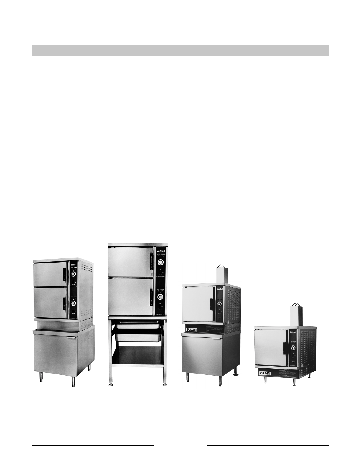
This manual is applic able for all models listed on the cover page. Several models are pic tured below for
reference.
Serial Numb er Break
Listed below, are t he beginning serial numbers for each model when the soli d state water level control (three
probe design) was added.
MODEL SERIAL
VSX-3 AP100704-9Q-4565
VSX-4 AP1007141-9Q-4615
VSX-5 AP1007555-11Q-5522
Steam Cooking
Pressure-less steamers offer an ef ficient way to produce m any foods in smal l portions or l ar ger batches.
Pressure-less, convection steam cooking will steam cook fresh foods or will steam defrost and cook frozen foods
providing the maximum color, flavor and nutriti onal value with the least expenditure of energy and labor . The
pressure-less steaming compartment allows the operator to open and close the door, anytime during a cooking
cycle. The steam suppl y will shut off when the door is opened, then re-start when the door is closed.
VSX7EC
VSX7EO
Page 3 of 40
VSX5GC
VSX5G
Page 4
VSX SERIES STEAMERS -GENERAL
SPECIFICATIONS
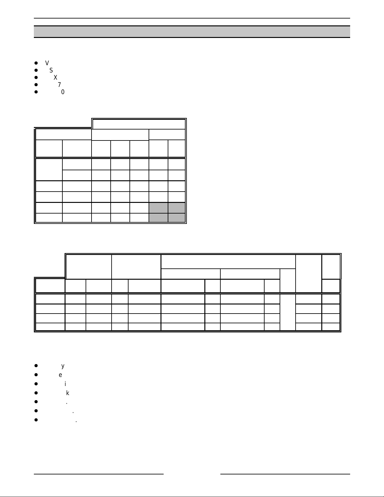
Model Designations
VSX3 - 3 pan unit.
VSX4 - 4 pan unit.
VSX5 - 5 pan unit.
VSX7 - Combi nation VSX3 and VSX4 unit.
VSX10 - Combi nation of two VSX5 units.
(based on 2.5 inch pan depth)
Electric Steamers
AMPERAGE
3 PHASE 1 PHASE
MODEL
TOTAL
KW
208V 240V 480V 208V 240V
7.5 std. 20.9 18.1 9.0 36.1 31.3
VSX3E
10.0 opt. 27.8 24.1 12.1 48.1 41.7
VSX4E 10.0 27.8 24.1 12.1 48.1 41.7
VSX5E 15.0 41.6 36.2 18.1 72.2 62.5
VSX7E 17.5 48.7 42.2 21.1
VSX10E 30 83.2 72.4 36.2
Gas Steamers
INPUT
BTU/HR
MODEL NAT. PROP. NAT. PROP. RECOMMEND MIN RECOMMEND MIN
VSX5G 45,000 45,000 3.5 5.0 7.0 5.0 11.0 7.0
VSX5GC 45,000 45,000 3.5 5.0 7.0 5.0 11.0 7.0 180 1.5
VSX7GC 90,000 90,000 3.5 5.0 7.0 5.0 11.0 7.0 360 3.0
VSX10GC 90,000 90,000 3.5 5.0 7.0 5.0 11.0 7.0 360 3.0
MANIFOLD
PRESSURE
(INCHES W.C.)
NATURAL PROPANE
LINE PRESSURE
(INCHES W.C.)
MAX
14.0
LOAD
(WATTS)
180 1.5
Water Supply
Supply pressure should be ........................ 20-80 psig
In line strainer f or suppl y line (Suppl ied)
Total dissolved solids (TDS)* .................... l ess than 60 ppm
Total alkalinity ........................................... less than 20 ppm
Silica ......................................................... less than 13 ppm
Chloride .................................................... less than 30 ppm
PH factor ................................................... 7 to 8
(*17.1 ppm = 1 grain of har dness)
AMPS
(MAX)
120V
60HZ
Page 4 of 40
Page 5
VSX SERIES STEAMERS -GENERAL
TOOLS
Standard
Standard set of hand tools.
VOM with an AC c ur r ent tester (any quality
VOM with a sensitivity of at least 20,000 ohm s
per volt can be used).
Gas leak checking equipment.
Special
CLR Treatm ent Kit (p/ n 817634) - Used to
remove Calci um/Lime/Rust from a steam
generator tank.
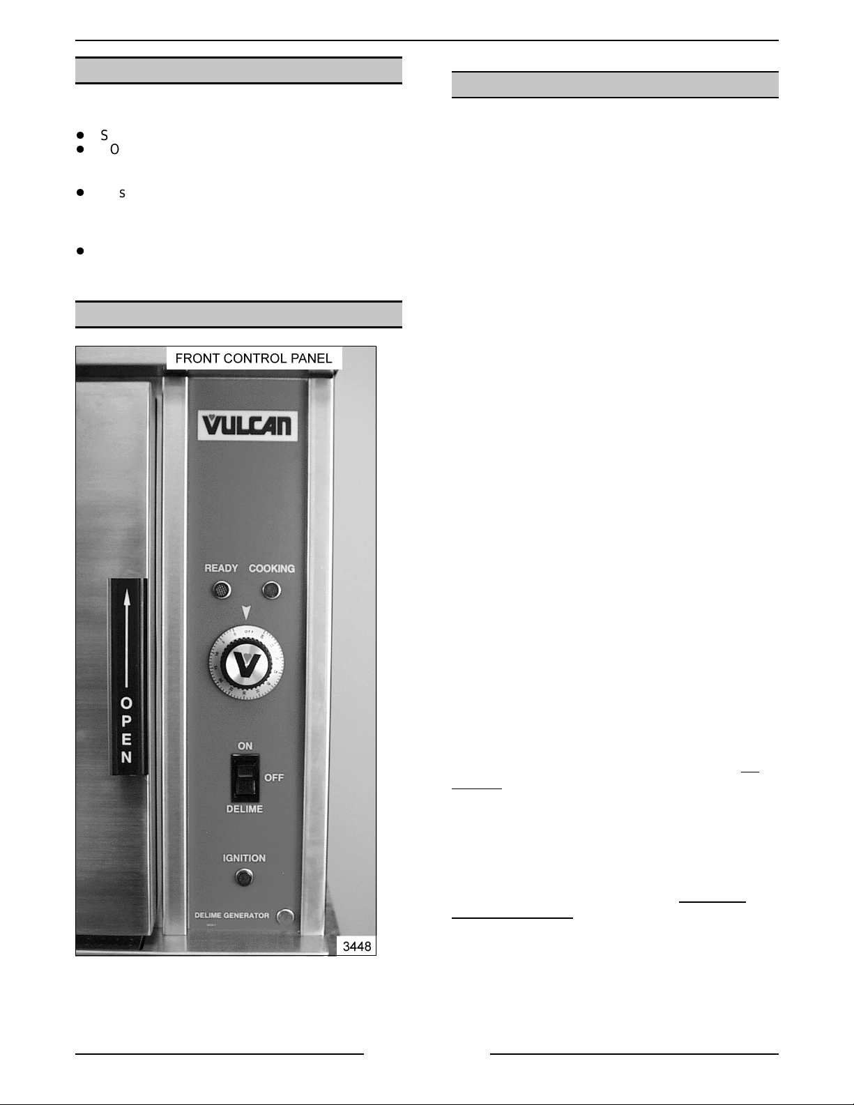
CONTROL LOCAT ION
WATER CONDITIONING
Furnishing the steam generator with soft water to
reduce scale formation is impor tant. Scal e formation
will reduce steam out put, cause prematur e
component failure, and shorten equipment life. Most
water supplies contai n scale producing m inerals
such as Calcium and M agnesi um. As steam is
generated, the mineral s remain and dissolve into
the water. As the concentration of these miner als
increases past a certai n point, they pr ec ipitate from
the water and coat the inside of t he tank, heating
element s, thermostat bulbs and water lev el probes.
Because of the high temperature of these surfaces,
the precipitated m inerals bake onto them and
become very difficult to remove.
This phenomenon c auses sev er al problem s:
1. Reduce the heat t r ansfer efficiency of t he
heaters.
2. Cause premature failure of the heaters.
3. Water level probes will give false readings.
4. Thermostat bulbs will sense temperature
incorrectly.
These problem s are common to any manufacturer's
steamer regardless of design, but t hey c an all be
prevented by furnishing the steam gener ator tank
with soft water. Vulcan recommends the water
contain l ess than 60ppm of “t otal dissolved solids”
(TDS) and have a PH factor between 7 to 8. These
water properties can be achieved by usi ng a
properly maintai ned water softener.
Other chemical pr oper ties in water supplies can also
affect good steam generation and vary fr om within
each state and locality.
The water level probes in the steam generator tank
use ions in the water to det ec t the water level.
not use
since it is "non conductive" and the water level can
not be detected.
NOTE:
remove mi nerals from the water.
fully demi neralized or de- ionized water
The use of strainers, or fibers will not
Do
(Gas Model Shown)
Therefor e, it i s recommended that a local water
treatm ent speciali st be c onsul ted before the
installation of any steam generating equipment.
Steamers that operate over a long peri od of time
without the benefit of a water softener, which have
developed a heavy scale build up, should be
cleaned bef or e using a water softener.
Page 5 of 40
Page 6
VSX SERIES STEAMER - REMOVAL AND REPLACEMENT OF PARTS
REMOVAL AND REPLACEMENT OF PARTS
COVERS AND PANELS
WARNING:
POWER TO T HE MACHINE AT THE MAIN
CIRCUIT BO X. P LA CE A TAG ON THE CI RCUIT
BOX INDICATING THE CIRCUIT IS BEING
SERVICED.
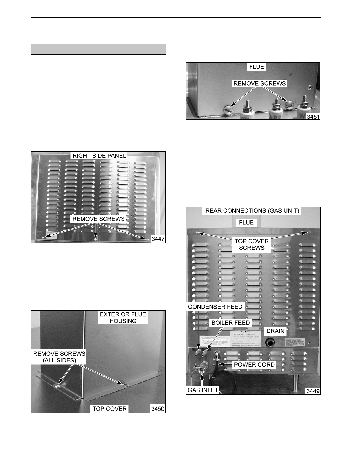
Right Side Panel
1. Remove screws from the bottom of the panel.
2. Sli de panel down to clear the top cover .
3. Rev er se proc edur e to install .
DISCONNECT THE ELECTRICAL
B. Remove the screws that secure the flue to
the tank and lift it off.
2. Push up on the rear of the cover and slide the
top cover forward to c lear the f r ont edge.
3. Lift the cover off the cabi net.
4. Rev er se proc edur e to install .
Left Side and Rear Panel
1. Remove the top cover screws an disconnect t he
utilities.
(Gas Model Shown)
Top Cover
1. Remove screws from the top rear of c over. If
steamer i s a gas model, follow steps 1A and 1B.
A. Remove the screws at the base of the
exterior flue housing and lift of f.
Page 6 of 40
Page 7
VSX SERIES STEAMER - REMOVAL AND REPLACEMENT OF PARTS
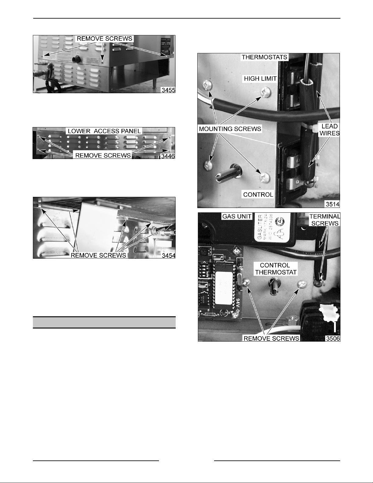
2. Remove the screws at the bott om of panel.
3. Remove the lower acc ess panels on the right
and left side of the unit to gain ac cess to the
lower compartment.
4. Remove the screws Inside the l ower
compartment that run along the top rear of the
base frame that secure the lip of the r ear panel.
replaced.
5. Remove screws that secure the thermostat.
NOTE:
base frame and the top li p of the small rear access
panel.
5. Pull the combination left side and rear panel off.
6. Rev er se proc edur e to install .
Rear panel lip is “sandwiched” between the
THERMOSTATS
WARNING:
POWER TO T HE MACHINE AT THE MAIN
CIRCUIT BO X. P LA CE A TAG ON THE CI RCUIT
BOX INDICATING THE CIRCUIT IS BEING
SERVICED.
1. Turn “off” t he water suppl y and allow hot parts to
cool down if necessary.
2. Remove the ri ght side panel as outlined under
"COVERS AND PANELS".
3. Manuall y drain the steam gener ator tank if
necessary, as outlined in "DRAIN TANK
MANUALLY”.
DISCONNECT THE ELECTRICAL
6. If r eplacing the control thermostat, fully loosen
the compression nut, slidi ng it away from tank,
then remove the bul b.
NOTE:
thermostat calibration and/or damage to therm ostat
may occur.
When installing, do not over tighten as
4. Disconnect t he lead wires from thermostat being
Page 7 of 40
Page 8
VSX SERIES STEAMER - REMOVAL AND REPLACEMENT OF PARTS
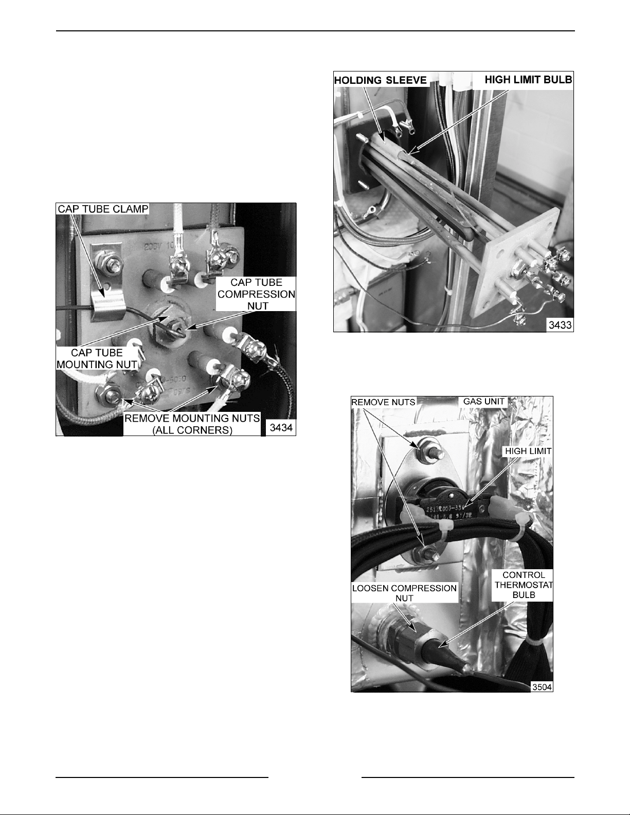
7. If r eplacing the high limit ther mostat:
A.
Electric Mo dels
1) Remove nut on capillary tube hold down
clamp.
2) Fully loosen the small capillary tube
compression nut and sl ide it away f r om
heater.
3) Remove large capillary nut from heater
base plate and slide it away from
heater.
5) Pull the bulb from its holding sleeve and
remove from the heater.
B.
Gas Model s
1) Remove t he nuts securing the
thermostat to the tank surface plate and
lift it off.
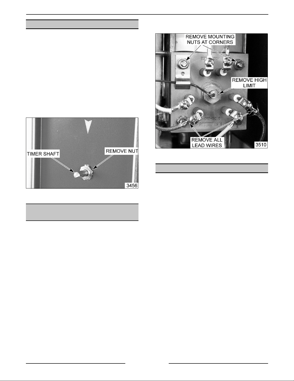
4) Remove t he r emaining nuts that secure
heater to the t ank and pull heater out
just enough to ex pose t he holding
sleeve on the element and the bulb.
NOTE:
wires together so the heating element c an be pulled
out without disconnecting the lead wires.
Cut the wire ties holding the heat er lead
8. Rev er se the procedure to install the new
thermostat and check for pr oper oper ation as
outlined under "CONTROL THE RM OSTAT
ADJUSTMENT".
Page 8 of 40
Page 9
VSX SERIES STEAMER - REMOVAL AND REPLACEMENT OF PARTS
TIMER
WARNING:
POWER TO T HE MACHINE AT THE MAIN
CIRCUIT BO X. P LA CE A TAG ON THE CI RCUIT
BOX INDICATING THE CIRCUIT IS BEING
SERVICED.
1. Remove the ri ght side panel as outlined under
"COVERS AND PANELS".
2. Pull timer knob from shaft.
3. Disconnect lead wires to timer.
4. Remove nut from timer shaft and remove timer
from the unit.
DISCONNECT THE ELECTRICAL
5. Remove the nuts that secur e the heater to the
tank and remove the heat er from the unit.
6. Rev er se proc edur e to install .
5. Rev er se the procedure to install.
HEATING ELEMENTS
(ELECTRIC)
WARNING:
POWER TO T HE MACHINE AT THE MAIN
CIRCUIT BO X. P LA CE A TAG ON THE CI RCUIT
BOX INDICATING THE CIRCUIT IS BEING
SERVICED.
1. Turn “off” t he water suppl y and allow hot parts to
cool down if necessary.
2. Remove the ri ght side panel as outlined under
"COVERS AND PANELS".
3. Manuall y drain steam generator tank if
necessary, as outlined under " DRA IN TANK
MANUALLY".
4. Disconnect t he heater lead wires and rem ove
the high limit thermostat bulb fr om heater as
outlined under “THERMOSTATS”.
DISCONNECT THE ELECTRICAL
GAS SOLENOID VALVE
WARNING:
POWER TO T HE MACHINE AT THE MAIN
CIRCUIT BO X. P LA CE A TAG ON THE CI RCUIT
BOX INDICATING THE CIRCUIT IS BEING
SERVICED.
WARNING:
BEFORE SERVICING THE UNIT.
WARNING:
DURING SERVI CING MUST BE CHECK E D FOR
LEAKS. CHECK USING A SOAP AND WATER
SOLUTION (BUBBLES). DO NOT USE AN OPEN
FLAME.
A. BEFORE LIG HTING UNIT, CHECK ALL
B. CHECK ALL JOINTS BEYOND GAS
1. Remove the ri ght side panel as outlined under
"COVERS AND PANELS".
2. Cut the wire t ies around “wire bundle” and trac e
the solenoid wires to
remove.
DISCONNECT THE ELECTRICAL
SHUT OFF THE GAS SUPPLY
ALL GAS JOINTS DISTURBED
JOINTS PRIOR TO THE GAS VALVE
(SOLENOID).
VALVE (SOLENOID) AFTER THE UNIT
HAS LIT.
there terminati ons and
Page 9 of 40
Page 10
VSX SERIES STEAMER - REMOVAL AND REPLACEMENT OF PARTS
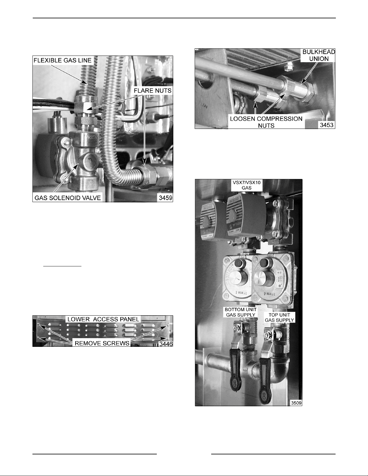
3. Loosen the compression nuts on the flexible gas
line then r emove line from the gas solenoid
valve and manif old.
B. Loosen the compression nuts on the
“condenser feed” and “tank feed” water lines
and place the l ines to the side.
NOTE:
compression nut on the “cold water condenser”
solenoid and rotate it out of the way.
6. Open the l ower cabinet base door to gain
If necessary, loosen the remai ning
access the gas solenoid valves.
(VSX5G SHOWN)
4. If r emov ing gas val ve from a single unit,
proceed to step 5. If rem oving gas solenoid
valve from a double unit, proc eed to step 6.
5. Turn “off” t he water suppl y to the “tank fill ” and
“cold water condenser” solenoi ds and
disconnect the fittings (bulkhead uni on) on the
opposite end
connections.
A. To access the compression fitt ings for the
incoming water connecti on, remove the
small access panel to the lower
compartment.
of the incoming water
7. Remove the gas solenoid valve f r om the pipe
8. Rev er se proc edur e to install and c hec k unit for
Page 10 of 40
nipple bel ow i t.
proper operati on.
Page 11
VSX SERIES STEAMER - REMOVAL AND REPLACEMENT OF PARTS
GAS PRESSURE REGULATOR
WARNING:
POWER TO T HE MACHINE AT THE MAIN
CIRCUIT BO X. P LA CE A TAG ON THE CI RCUIT
BOX INDICATING THE CIRCUIT IS BEING
SERVICED.
WARNING:
BEFORE SERVICING THE UNIT.
WARNING:
DURING SERVI CING MUST BE CHECK E D FOR
LEAKS. CHECK USING A SOAP AND WATER
SOLUTION (BUBBLES). DO NOT USE AN OPEN
FLAME.
A. BEFORE LIG HTING UNIT, CHECK ALL
B. CHECK ALL JOINTS BEYOND GAS
1. Remove the ri ght side panel as outlined under
"COVERS AND PANELS".
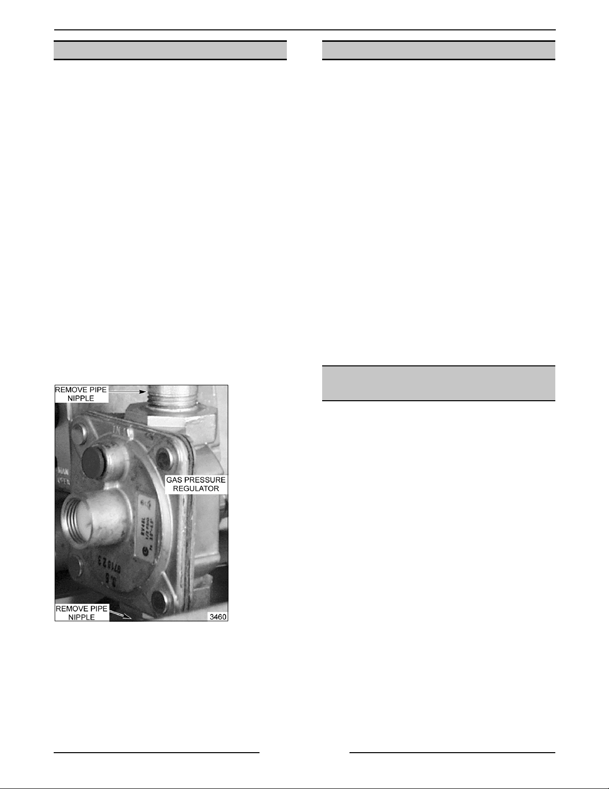
2. Remove the gas solenoid valve as outline under
“GAS SOLENOID VALVE”.
3. Remove the gas pressure regulator from the
pipe nippl e below it.
DISCONNECT THE ELECTRICAL
SHUT OFF THE GAS SUPPLY
ALL GAS JOINTS DISTURBED
JOINTS PRIOR TO THE GAS VALVE
(SOLENOID).
VALVE (SOLENOID) AFTER THE UNIT
HAS LIT.
FLAME SENSE PROBE (GAS)
WARNING:
POWER TO T HE MACHINE AT THE MAIN
CIRCUIT BO X. P LA CE A TAG ON THE CI RCUIT
BOX INDICATING THE CIRCUIT IS BEING
SERVICED.
WARNING:
BEFORE SERVICING THE UNIT.
1. Cut the wire t ies around “wire bundle” and trac e
the Flame Sense Probe (FSP) wir e to an in-line
splice (but t connector) and cut the wire close to
the connector.
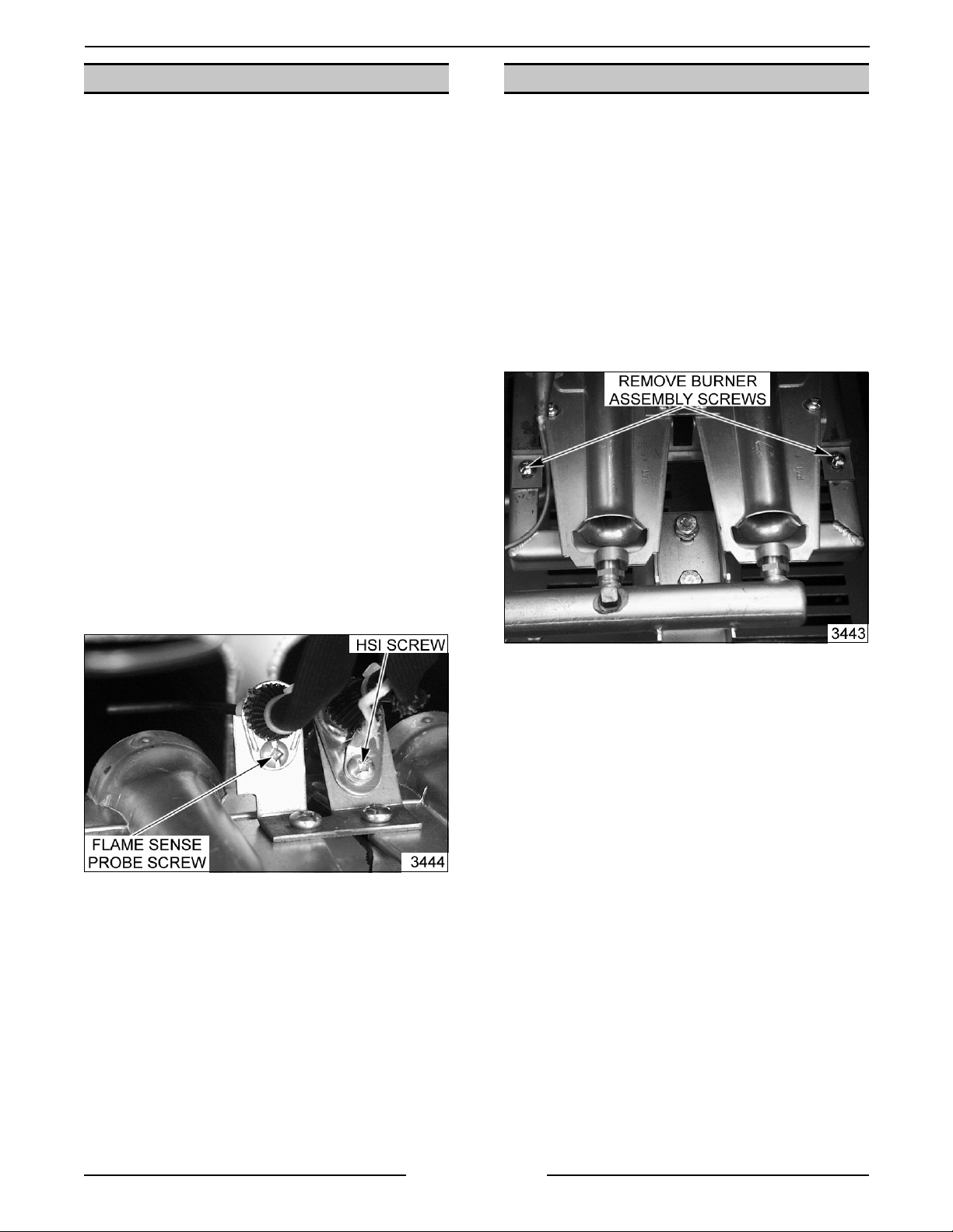
2. Remove the screw holdi ng the flame sense
probe onto the m ounting bracket and lif t out.
3. Rev er se the procedure to install a new probe
then check FSP for proper oper ation as outli ned
under “FLAME SENSE PROBE”.
NOTE:
have t o be c ut close to the connec tor and the wire
insulation stripped back approximately 0.250 i nc h to
install a new connector.
DISCONNECT THE ELECTRICAL
SHUT OFF THE GAS SUPPLY
The opposite end of the in-line splice will
WATER LEVEL CONTROL
BOARD
4. Rev er se the procedure to install.
5. Adjust the gas regulator pressure as outlined
under “MANIFOLD PRESSURE
ADJUSTMENT”.
6. Check unit for proper operation.
WARNING:
POWER TO T HE MACHINE AT THE MAIN
CIRCUIT BO X. P LA CE A TAG ON THE CI RCUIT
BOX INDICATING THE CIRCUIT IS BEING
SERVICED.
1. Remove the ri ght side panel as outlined under
"COVERS AND PANELS".
2. Disconnect t he lead wires from the water level
control board (WLC) .
3. Remove mount ing screws.
4. Move board to the left and rotate outwards when
removing, t o clear wire bundle.
5. Rev er se the procedure to install, then chec k unit
for proper operation.
DISCONNECT THE ELECTRICAL
Page 11 of 40
Page 12
VSX SERIES STEAMER - REMOVAL AND REPLACEMENT OF PARTS
HOT SURFACE IGNITOR (GAS)
WARNING:
POWER TO T HE MACHINE AT THE MAIN
CIRCUIT BO X. P LA CE A TAG ON THE CI RCUIT
BOX INDICATING THE CIRCUIT IS BEING
SERVICED.
WARNING:
BEFORE SERVICING THE UNIT.
1. Remove the ri ght side panel as outlined under
"COVERS AND PANELS".
2. Cut the wire t ies around “wire bundle” and trac e
the wire for the Hot Surface Ignit or ( HS I) to an
in-line splice (but t connector) and cut the wire
off close to the connector.
3. Remove the screw that holds the flame sense
probe and ground terminal wire ont o the
mounti ng bracket and lift out .
4. Rev er se the pr ocedure to instal l then check HSI
for proper operation as outlined under “HOT
SURFACE IGNITOR”.
DISCONNECT THE ELECTRICAL
SHUT OFF THE GAS SUPPLY
GAS BURNER
WARNING:
POWER TO T HE MACHINE AT THE MAIN
CIRCUIT BO X. P LA CE A TAG ON THE CI RCUIT
BOX INDICATING THE CIRCUIT IS BEING
SERVICED.
1. Remove the ri ght side panel as outlined under
"COVERS AND PANELS".
2. Remove the screws securing the burner
mounti ng bracket to the bur ner box frame.
3. Sli de the burner for ward enough to c lear the gas
nozzles and lift it out.
DISCONNECT THE ELECTRICAL
NOTE:
have t o be c ut, close to t he c onnec tor and the wire
insulation stripped back approximately 0.250 i nc h to
install a new connector.
The opposite end of the in-line splice will
4. Remove the screws securing the burners to the
mounti ng bracket and lift t he bur ner s off.
5. Rev er se proc edur e to install then check for
proper operati on.
NOTE:
sure burner flame is not impinging on the opening of
the burner box.
When c hec king for pr oper oper ation, m ak e
Page 12 of 40
Page 13

VSX SERIES STEAMER - REMOVAL AND REPLACEMENT OF PARTS
GAS IGNITION MODULE
WARNING:
POWER TO T HE MACHINE AT THE MAIN
CIRCUIT BO X. P LA CE A TAG ON THE CI RCUIT
BOX INDICATING THE CIRCUIT IS BEING
SERVICED.
1. Remove the ri ght side panel as outlined under
"COVERS AND PANELS".
2. Disconnect t he c ontrol wires by pulling of f wire
harness connector locat ed on the right side of
module.
3. Remove screws that secure the m odule to the
control boar d and lif t off.
DISCONNECT THE ELECTRICAL
3. Manuall y drain steam generator tank if
necessary, as outlined under " DRA IN TANK
MANUALLY".
4. Disconnect t he lead wire fr om each water level
probe and then remove probes from tank. Mark
probes accordingl y for replac ement.
4. Rev er se the pr ocedure to instal l the new gas
ignition module then check f or pr oper oper ation.
STEAM GENERAT OR TANK
WARNING:
POWER TO T HE MACHINE AT THE MAIN
CIRCUIT BO X. P LA CE A TAG ON THE CI RCUIT
BOX INDICATING THE CIRCUIT IS BEING
SERVICED.
1. Turn “off” t he water suppl y and allow hot parts to
cool down if necessary. On gas models, shut the
gas supply “off” to the unit.
2. Remove the ri ght side panel and top cover as
outlined under "COVERS AND PANE LS " .
DISCONNECT THE ELECTRICAL
Page 13 of 40
(
Electric Model Shown)
Page 14

VSX SERIES STEAMER - REMOVAL AND REPLACEMENT OF PARTS
5. Disconnect t he st eam lines on the top right and
left side of the tank, the water fill tube, the drain
line, then the delime li ne at the bottom left
corner.
7. Gas Model Only
A. Remove the burner assembly and place to
the side.
B. Remove the bolts that secure the manifold
to the burner box frame and place to t he
side.
C. Remove the surface high limit and the
control t hermostat bul b from the tank.
(Gas Model Shown)
6. Elect r ic Models Only - For gas models proceed
to step 7.
A. Remove the heater lead wir es, c ontrol and
high li mit thermostat bulbs, then remove the
heater fr om the tank.
B. To remove tank, loosen
side mounting stud of the tank and remove
the two nuts from the mounting studs on the
right side of the tank.
(Electric Model Shown)
the nut on the l eft
D. Remove the combination Left side and Rear
panel as outlined under “COVERS AND
PANELS”.
8. Remove the nuts and washers from studs on
each side of t he tank that secure i t to the steam
cavity and lift t he steam generator t ank out.
9. Rev er se proc edur e to install and c hec k unit for
proper operati on.
WATER LEVEL PROBES
WARNING:
POWER TO T HE MACHINE AT THE MAIN
CIRCUIT BO X. P LA CE A TAG ON THE CI RCUIT
BOX INDICATING THE CIRCUIT IS BEING
SERVICED.
1. Remove the top cover as outl ined under
"COVERS AND PANELS".
2. Disconnect t he lead wire to water level pr obes.
DISCONNECT THE ELECTRICAL
C. Push the r ight side of the tank toward the
rear of t he unit enough to clear the studs
from the mounting bracket t hen, pull tank
toward the right to remove.
D. Reverse the procedure to install and c heck
unit for proper operation.
Page 14 of 40
Page 15

VSX SERIES STEAMER - REMOVAL AND REPLACEMENT OF PARTS
3. Unscrew probes from steam generator tank .
(Gas Model Shown)
NOTE:
Remove all acc umulated deposi ts from the insulator
using a soft cloth.
NOTE:
insulators.
NOTE:
assembling.
Probe should be cleaned thoroughly.
Do not use anything abrasi ve on the
If t he pr obes are dirty, delime t he unit after
3. Cut the wire t ies around “wire bundle” and trac e
the power wires for the sol enoid valve being
servi ced back to there t er minations and remove.
4. Disconnect t he fittings on each side of the valve
and remove the valve from the unit.
5. Rev er se proc edur e to install .
(Electric Model)
4. Rev er se proc edur e to install .
NOTE:
outlined under "STEAM GENE RA TOR TANK
CLEANING".
Perform a steam generator tank cleaning as
FILL AND COLD WATER
SOLENOID VALVES
WARNING:
POWER TO T HE MACHINE AT THE MAIN
CIRCUIT BO X. P LA CE A TAG ON THE CI RCUIT
BOX INDICATING THE CIRCUIT IS BEING
SERVICED.
Removal
1. Turn “off” t he water suppl y to the steamer.
2. Remove the ri ght side panel as outlined under
"COVERS AND PANELS".
DISCONNECT THE ELECTRICAL
(Gas Model)
Disassembly
NOTE:
removed from the unit for cl eaning to prevent
damage to the lines and fittings when the stem is
removed from the body.
1. Remove the coi l assembly from the valve stem .
2. Disconnect t he fittings on each side of the valve
NOTE:
that f its these solenoids is available, the body of the
valve might be hel d wi th vise grips and then,
remove the stem wi th your spanner wrench. If this
can be done without damaging the line or fittings,
proceed to step 5.
3. Clam p the body of the valve in a vise.
4. Mark a scri be line
It is recommended that the v alve be
and remove it from t he unit. Read note before
removing.
If a standard or adjustable spanner wrench
on the stem nut to the v alve
body for proper retightening.
Page 15 of 40
Page 16

VSX SERIES STEAMER - REMOVAL AND REPLACEMENT OF PARTS
5. Use a hammer and punc h to turn the stem
counterclockwise to remove the stem from the
body.
6. All par ts are now accessible for inspection and
cleaning.
A. Check rubber seal on bottom of plunger.
B. Check plunger spring.
DRAIN VALVE
WARNING:
POWER TO T HE MACHINE AT THE MAIN
CIRCUIT BO X. P LA CE A TAG ON THE CI RCUIT
BOX INDICATING THE CIRCUIT IS BEING
SERVICED.
Removal
1. Turn “off” t he water suppl y to the steamer.
2. Remove the ri ght side panel and top cover as
outlined under "COVERS AND PANE LS " .
3. Manuall y drain the steam gener ator tank if
necessary, as outlined under " DRA IN TANK
MANUALLY".
4. Disconnect t he lead wires from the water level
control and the ground wire from the control
panel if necessary, to access the drai n valve
connections.
5. Disconnect t he fittings on each side of the valve
and remove the valve from the unit.
DISCONNECT THE ELECTRICAL
C. Check "O"ring in valve body.
D. Check por ts in valve body .
6. Rev er se proc edur e to install .
Disassembly
1. Turn “off” t he water suppl y to the steamer.
2. Remove the ri ght side panel as outlined under
"COVERS AND PANELS".
3. Manuall y drain the steam gener ator tank if
necessary, as outlined under " DRA IN TANK
MANUALLY".
7. Rev er se proc edur e to install .
4. Remove the cover f r om the drain valve m otor.
Page 16 of 40
Page 17

VSX SERIES STEAMER - REMOVAL AND REPLACEMENT OF PARTS
5. Loosen the screws from the motor assembly
and lift up on the m otor to rem ove it from the
valve body.
6. Remove the screws from the cover plate and
remove the cover plate and ball assembly from
the v alve body .
NOTE:
stem perpendi c ular to the i nlet and outlet of the
drain valve. The valve will be in the open position
whenever power is removed from t he motor.
7. Rev er se proc edur e to install .
When r e-install ing, place flat sides of ball
Page 17 of 40
Page 18

VSX SERIES STEAMER - REMOVAL AND REPLACEMENT OF PARTS
DOOR
WARNING:
POWER TO T HE MACHINE AT THE MAIN
CIRCUIT BO X. P LA CE A TAG ON THE CI RCUIT
BOX INDICATING THE CIRCUIT IS BEING
SERVICED.
Removal
1. Remove top cover as outlined under "COVERS
AND PANELS".
2. Open the door.
3. Pull hinge rod up.
4. Rev er se the procedure to install, m ak ing sure
the door bushings are in place.
DISCONNECT THE ELECTRICAL
Gasket
1. Open the door.
2. Remove screws from the gasket plate.
3. Pull the gasket plate out from the door housing
and remove the gasket.
4. Positi on the new gasket on the gasket plate and
rever se t he pr oc edur e to install . Adjust the door
as outlined under "DOOR SEALING
ADJUSTMENT".
NOTE:
this will compress the gasket excessively and
interfere with proper door seal ing.
Do not ov er tighten gasket plate screws as
Page 18 of 40
Page 19

VSX SERIES STEAMER - REMOVAL AND REPLACEMENT OF PARTS
Handle
1. Open the door.
2. Remove screws from the top and bottom of the
door.
3. Pull the “inner” door panel out from the door
housing with the gasket plate and gasket stil l
attached.
Latch Assembly
1. Open the door.
2. Remove screws from the top and bottom of the
door.
3. Pull the “inner” door panel out from the door
housing with the gasket plate and gasket stil l
attached.
4. Remove the screws from the side edge of the
door that secure the latch mec hanism and
remove the lat ch from the door.
4. Remove the nuts and spacers f r om the handle
screws and remove the handle fr om the door.
NOTE:
diamet er fits into the slot in the door and the l atch
lever must rest on t op of the handle latch screw.
When installing the spacers, the smaller
NOTE:
top of t he handle latch screw.
5. Rev er se proc edur e to install .
When installing, the latch lever must rest on
5. Rev er se proc edur e to install .
Page 19 of 40
Page 20

VSX SERIES STEAMER - SERVICE PROCEDURES AND ADJUSTMENTS
SERVICE PROCEDURES AND ADJUSTMENTS
WARNING:
MEASUREMENTS WHILE POWER IS APPLIED TO THE MACHINE. EXERCISE EXTREME CAUTION AT ALL
TIMES. IF TEST POI NT S ARE NOT EASI LY ACCESSIBLE, DISCONNECT POWER, ATTACH TEST
EQUIPMENT AND REAPPLY POWER TO TEST .
STEAM GENERAT OR CLEANING
Follow the pr oc edur e as outlined in t he " C LR
TREATMENT KIT" to remove the
Calcium/Lime/Rust buil d- up inside the tank, water
level probes, elec tric elements and drain system .
The CLR Kit c ontains, C.L.R. c leaner, f unnel,
measuring cup, and G" tubing.
In addition but not f ur nished in kit , rubber gloves
should be used.
CERTAIN PROCEDURES IN THIS SECTION REQUIRE ELECTRICAL TEST OR
NOTE:
hrs.
Factory default time set on t he boar d is 100
DELIME BOARD OPERATION
AND ADJUSTMENT
CONTROL THERMOSTAT
The delime timer board track s the c umulative
cooking hours and lights the deli me light on the
control panel when the delime tim er boar d r eac hes
a preset number of cooking hours. A n LE D on the
delime timer board lights indicating cook time hours
are accumulating.
After the delime timer board has accumul ated the
preset number of cooking hours, the delime light will
light. It will stay lit until the power switch is moved to
the delime positi on or off. If t he power switch is
turned “off” and then t urned “on” without going t o the
delime position, the delime light will relight.
1. To adjust t he length of c ooking hours before the
delime light will come on:
2. Access the delime ti mer board.
The procedure outlined below is to adjust the
thermostat temperat ur e setting to a “ready” state
which is slight ly below a continuous boi l, (212°F) to
achieve the best “cooking” and steamer
performance.
When a c ook ing time is set on the ti mer, the delay
tim e for the steam generator to deliver a high quality
and volume of steam into t he cooking com par tment
will be minimal.
Correctl y identifying the amount of steam coming
out of t he por ts is subjective. To help determine this,
does the steam coming out of the ports exhibit the
following:
ADJUSTMENT
Position the switches in the “on” or “off” position to
obtain the desired hours. The number of switches
that are positioned “on” or “off” set the tot al hours. It
does not matter which individual switch is “on” or
“off”.
HRS 30 50 100 150 200
SWITCH
POSITION
ON 0123ALL
OFF ALL 3 2 1 0
Page 20 of 40
1. Appear to be coming out under pr essure.
2. Create a distinctive “whistling” sound during
steaming.
3. Produce a good “cloud” of steam in the cooking
compartment.
If t he steaming meets the above criteria, the
thermostat is set correctly.
1. Remove the ri ght side panel as outlined under
"COVERS AND PANELS.”
Page 21

VSX SERIES STEAMER - SERVICE PROCEDURES AND ADJUSTMENTS
2. Turn the t her mostat adjustment stem full y
clockwise for a starting position.
3. Open the water valve and turn the power switch
"on.”
4. Open the steam compartment door whil e the
steam generator tank is heating up, and wait for
“drif t steam” to begin coming out of the steam
ports. Approximat e time 10 minutes.
NOTE:
until thermostat temperature is satisfied and the
“ready” li ght comes on.
5. Once “drift” steam is seen coming out of the
The door switch has no effect during preheat
steam ports, sl owly turn the thermostat
adjustment CCW until the thermostat “opens”
and the ready light comes on.
MODEL APPROXIMATE
TIME FOR STEAM
TO ENTER
COMPARTMENT
ELECTRIC 5 sec.
GAS 13 sec.
NOTE:
ready light stays “on” (heat not on) then the
thermostat is still satisfied. To shorten the wait time
until the heat comes on agai n, turn the power switch
“off” for several seconds to drai n some hot water out
of the t ank , then turn the switc h bac k “on”. At this
point, t he tank should begin filling with cold water,
bringing t he temperatur e down and causing t he
thermostat to call for heat. Repeat if nec essary.
If after inc reasing the thermostat setting, the
C. I f steam comes out of t he por ts like the
steamer was in a “cooki ng mode” and the
ready light never c omes on, the set point
temperat ure is too high. P r oc eed to step D.
D. Adjust the setting 1/8 of a turn CCW to
decrease temperature set point and repeat
step 6 until st eam exi ts the ports in the time
listed.
E. If steam comes out of the ports in the time
listed above, then t hermostat i s set
correctly.
F. After adjusting the thermostat to it s hi ghest
setting and steam does not come out of the
ports as described, then replace the
thermostat.
DRAIN TANK MA NUALLY
NOTE:
ports along with “drift” steam, then the tank water
has reached too high of a temperature and is
boili ng. The thermostat setting must be adjusted
down as indicated above.
6. With the door still open, set a time on the cook
If water begins to drip “heavily” out of steam
tim er and depress the door switch button.
Immediately after depr essing t he door switc h
button, begi n c ounting the seconds until steam
is “seen” coming out of the ports.
A. If i t takes longer than t ime listed in the char t
below, the thermostat setti ng is too low and
must be increased. Proceed to step B.
B. Adjust the setting 1/8 of a t ur n CW to
increase the set poi nt temperat ur e and
repeat step 6 until steam exits the ports i n
the time listed.
WARNING:
POWER TO T HE MACHINE AT THE MAIN
CIRCUIT BO X. P LA CE A TAG ON THE CI RCUIT
BOX INDICATING THE CIRCUIT IS BEING
SERVICED.
1. Turn “off” t he water suppl y to the steamer.
2. Remove the ri ght side panel as outlined under
3. Remove the cover f r om the drain valve m otor
4. Loosen the screws from the motor assembly
5. Turn the stem of the dr ain valve so t hat it is
Page 21 of 40
DISCONNECT THE ELECTRICAL
"COVERS AND PANELS".
as outlined under “DRAIN VALVE”.
and lift up on the m otor to rem ove it from the
valve body.
perpendicular to the inlet and outlet lines. Thi s
should drain the tank unless the drain l ine is
clogged.
Page 22

VSX SERIES STEAMER - SERVICE PROCEDURES AND ADJUSTMENTS
DOOR SEALING ADJUSTMENT
1. Check the door gasket quality. If damaged or
worn, replace as outl ined under “DOOR”.
2. Loosen screws until the screw heads no longer
touch the gasket plate.
3. Tight en scr ews until screw head touches gasket
plate and at t hat point begin counting turns.
4. Tight en all screws approximately two turns.
5. Close the door and check unit for proper
operation.
6. If nec essary, tighten all screws an additional ½
turn and repeat step 5.
7. Repeat step 6 unti l the door cl oses properl y and
no steam “leaks” are seen around the gasket
seal.
DOOR LATCH ADJUSTMENT
Should the cooker door jam and c an not be opened,
DO NOT FORCE OR PRY
occur.
the door as damage wil l
To ad just
1. Reinstall the strik er with the slot pointing
2. Close the door to c enter the strik er in the oval
3. Open the door and chec k the strikers’ sl ot for
:
upwards and “hand tighten” nut onl y .
mounti ng hole.
horizontal alignment. The slot on the striker
must be kept hor izontal in order for the door
latch to c atch it proper ly and latch.
First, try lifting up on the bottom of the door at the
handle end, to disengage the latch.
If t hat does not work, remove the right side panel.
The striker that catches on the “door latch” is
located behi nd the front face of the cooking cavit y .
Remove the nut from the striker and thi s will release
it from the panel.
Once the nut and washer have been removed, door
will open freely.
Remove any burrs on the stri k er that may cause the
latch to stick.
Reinstall the striker and adjust, so door will not jam.
4. Once the proper slot alignment has been set,
hold the striker close to i ts base using a rag and
vise grips, then tighten the strik er nut. Be
careful not to damage the striker “slot” when
tightening or door may not latch properly.
NOTE:
to turn and change al ignment.
Do not over tighten as the striker will begin
Page 22 of 40
Page 23

VSX SERIES STEAMER - SERVICE PROCEDURES AND ADJUSTMENTS
MANIFOLD PRESSURE
ADJUSTMENT
WARNING:
POWER TO T HE MACHINE AT THE MAIN
CIRCUIT BO X. P LA CE A TAG ON THE CI RCUIT
BOX INDICATING THE CIRCUIT IS BEING
SERVICED.
WARNING:
BEFORE SERVICING THE UNIT.
1. Remove right side panel as outli ned under
"COVERS AND PANELS".
2. Remove the 1/4" NP T pipe plug from the
manifold and att ac h a manomet er .
3. Remove the adjustment screw cap to access the
pressure adjustment screw.
A. To increase pressure, turn the screw
B. To decrease pressure, turn the screw
DISCONNECT THE ELECTRICAL
SHUT OFF THE GAS SUPPLY
clockwise
counterclockwise
minimum st ated, then the manifold pressure can not
be set correctly.
6. Once the cor rect pressure has been set, turn the
power switch “off”, replace t he adjustment
screw cap and manifold pipe plug.
7. Check unit for proper operation.
4. Plug i n the unit, t urn “on” the gas and set the
power switch to “on”. If adjusting pressure on a
double unit, both must be “on” before a pressure
adjustment is made.
NOTE:
Accurate gas pressure adjustments can only
be made with the gas “ON” and the burner lit.
5. After the burner lights, set the pressure as
outline below:
PRESSURE READINGS
(INCHES W.C.)
GAS TYPE MANIFOLD
NATURAL 3.5 7.0 5.0
PROPANE 5.0 11.0 7.0
RECOMMENDED MIN MAX
* If t he incomi ng line pressure is
LINE
less than
the
14
Page 23 of 40
Page 24

VSX SERIES STEAMER - SERVICE PROCEDURES AND ADJUSTMENTS
FLAME SENSE PROBE (GAS)
WARNING:
POW E R TO BE APPLIED TO THE UNI T DURING
THE TEST. USE EXTREME CAUTION AT ALL
TIMES.
1. Assure that the unit has a proper ground, correc t
polarit y and that the value of incom ing voltage
is correct.
A. Check the flame sense voltage (burner on)
THE FOLLOWI NG ST EPS REQUIRE
between the fl ame sense lead wire
termination i n the ignition module edge
connector and ground wit h a V OM set on
DC volts. The voltage measurement wil l
fluc tuate but should be no l ess than 20
VDC.
2. Perf or m a v isual check to determine if the flame
sense probe is in the upper portion of flame. If
the probe is bent or not in the upper port ion of
the flame then check for alignment and adjust
as necessary.
A. The center line of the pr obe shoul d be
approximately 1 15/16 inches from the f ac e
of the burner and 5/16 inches up fr om the
center line of the bur ner .
B. If voltage is less than indicat ed, replace
flame sense probe and check unit for proper
operation.
3. If no adjustments can be made to the probe to
correct its alignment then replac e and c hec k
unit for proper operation.
Page 24 of 40
Page 25

VSX SERIES STEAMER - SERVICE PROCEDURES AND ADJUSTMENTS
HOT SURFACE IGNITOR (GAS)
1. Check to see if hot surface ignitor is operating
during
A. Visual verificati on - HS I should be heating
B. Voltage verification - check f or 24V A C to
ignition trial
up “glowing brightly” to ignite gas.
HSI termination on the edge connector to
ground.
by:
HEATING ELEMENT (ELECTRIC)
WARNING:
POW E R TO BE APPLIED TO THE UNI T DURING
THE TEST. USE EXTREME CAUTION AT ALL
TIMES.
1. Check voltage at the heating element terminals.
A. If voltage is correct then proc eed to step 2.
B. If voltage is not correct, c hec k the following:
2. Check current draw (amps) through the heat ing
element lead wires using an amp clamp meter.
A. If curr ent draw is correct then heating
B. If curr ent draw is not correct then proceed to
THE FOLLOWI NG ST EPS REQUIRE
1) Voltage supply to the unit.
a. Fuses or breaker blown.
b. Power to contactor coils.
c. Contactors not pulling in.
(Mechanical)
element is ok.
step 3.
WARNING:
POWER TO T HE MACHINE AT THE MAIN
CIRCUIT BO X. P LA CE A TAG ON THE CI RCUIT
BOX INDICATING THE CIRCUIT IS BEING
SERVICED.
2. Unplug the edge connec tor from the ignition
module and chec k resistance between HSI lead
wire and ground.
CONDITION
COLD 1 - 4
DISCONNECT THE ELECTRICAL
HSI
HOT 8 - 10
RESISTANCE
(approx. Ohms)
3. Remove the lead wires from the heating
element and c heck the element resistance using
a VOM.
A. If resistanc e r eadings are not correct ,
replace heating element.
4. Check unit for proper operation.
AMPERAGE
VOLTAGE
208 7.5 36.1 20.9 17.4
240 7.5 31.3 18.1 23.1
480 7.5 9.0 30.6
208 10 48.1 27.8 12.96
240 10 41.7 24.1 17.28
480 10 12.1 23.01
208 15 72.2 41.6 8.64
240 15 62.5 36.2 11.52
480 15 18.1 15.36
TOTAL
KW
PER LINE
1 PH 3 PH
RESISTANCE
PER LINE
(OHMS)
NOTE:
+5/-10 %.
Page 25 of 40
Values in the table are nominal. Tolerance is
Page 26

VSX SERIES STEAMER - ELECTRICAL OPERATION
ELECTRICAL OPERATION
COMPONENT FUNCTION
1A Delime Timer Board
Buzzer
1CON & 2CON
Heater Contactor
1-3HTR Heaters
1K Relay
2K Relay
3K Relay
1T
2T
Ignition Module
................. Signals end of cook cycle, must be t urned “off” manually .
.......... Heat water in Steam Generator tank . (electr ic model s onl y )
............... Suppli es power to control cir c uit when steam is bei ng gener ated and the tank
............... Prevents operation of the cook timer until initial fill and heat is complete.
............... Operates drain motor and resets delime timer board when the power switch is
.................... Provides 12VAC power to the delime board.
.................... Provides 24VAC power to ignition control module and HSI. (gas models only)
......... Controls and monit ors gas heating. Applies power to HSI for burner igniti on,
. . . Tracks the cumulative cooking hours by using a cur r ent sensor to monitor
current flow through the cold water condenser solenoid lead, then signal’s
operator to perform delime pr oc edur e after the steamer has operated in cook
mode f or a preset number of hours.
......... Controls power to tank heaters. (electric models only)
water level drops below the low level pr obe.
moved to the delime position.
monit ors flame presence through FSP, c ontrols 5 second purge time and 8.5
second ignition trial tim e and powers gas solenoid valve. (gas models only)
1LT Read y Light
2LT Delime Light
3LT Cook Light
4LT Ignition Light
High Level Probe
Low Level Probe
Low Level Cut Off Probe
FSP (Flame Sense Probe)
HSI (Hot Surface Igni t er)
1M Drain Mot or
......... Indicates steam generator tank is up to tem per ature and cooking can begin.
........ Indicates preset number of cook time hours have accumulated and the tank
.......... Indicates cook timer has been set and a cook cycle is in process.
........ Indicates gas burner is on. (gas models only)
......... Monitors tank water level and signals the WLC when tank is full.
......... Keeps the WLC relay coil HL energiz ed when the water level drops below the
.......... Controls the tank drain. (normally open valve, water flows when de-energized)
should be delimed.
high level probe.
. . . Monitors tank water level and r emov es el ec trical power to the LLCO relay when
the water level drops below the low level cut off probe.
. . Supplies a current signal back to the igniti on module indicating t he pr esence of a
flame. (gas models only)
. . When Ignition module applies power, the el ement heats up to very high
temperat ures causing gas igniti on. (gas models only)
Page 26 of 40
Page 27

VSX SERIES STEAMER - ELECTRICAL OPERATION
1S Power Switch
2S Door Switch
1SOL Fill Solenoid
2SOL Cold Water Solenoid
GAS Valve Solenoid
1TAS High Limit
Thermostat
2TAS Control Th ermostat
1TR Timer
........ Controls electrical power to the control circuit and delime c ircuit.
.......... Removes electrical power to the timer when the door is opened and the control
....... Controls tank water supply. (normall y c losed val ve, water flows when energized)
...... Allows gas flow to burner when solenoid i s energized. A normally closed val ve.
............. Will not allow heater contactor (on elect r ic model s) or igniti on module (on gas
.............. On electric models it contr ols the cold water solenoi d and power t o the heater
thermostat is open.
. Controls cold water supply going into drain to mi x and condense exhaust steam .
(normally closed valve, water flows when energized)
(gas models only )
models) t o ener gize if the tank temperature goes beyond 125°C (257(F).
. . On electric models it cycles power to heater contactors. O n gas m odels it cycles
power to the igni tion control module. On either model, this will maintain the
steam generator tank set point temperature, when no time is on cook t imer.
contactors. On gas models it c ontrols the cold water solenoid and power to the
ignition control module. T his occurs on either model after the tank reaches its set
point temperature and time is di aled into the timer. Also, energiz es the buz zer
when time expires.
WLC (Water Level
Control Board)
........... Monitors water level probes to control the tank water level and heater c ontactors.
Individual LE D’s on board light up when water level reaches LLCO and t hen HL
probes. W hen water level drops below one of these probes, LED goes out.
Page 27 of 40
Page 28

Electric Models
VSX3E, 4E & 5E
VSX SERIES STEAMER - ELECTRICAL OPERATION
COMPONENT LOCATION
VSX7E & 10E
Page 28 of 40
Page 29

Gas Models
VSX5G
VSX SERIES STEAMER - ELECTRICAL OPERATION
VSX 7G & 10G
Page 29 of 40
Page 30

VSX SERIES STEAMER - ELECTRICAL OPERATION
WATER LEVEL CONTROL OPERATION
The water level cont r ol (WLC) has line voltage acr oss terminals 11 and 12 which powers the pri mary side of the
transformer. The secondary si de of the transformer provides power to t he c ontrol by a series path t hr ough
chassis ground; through the water in the steam generat or tank; through the water level probes; to the i nternal
relay coils on the control. The other side of the secondary windi ng is attached to t he c ontrol that directs the power
to the other side of the internal rel ay c oils. As water enters the t ank , the water becomes part of the ci r c uit. As the
water level reaches the probes, t he c ircuit with that particular probe is completed to the water level contr ol, thus
energizing the internal relay coi l. LED’s on the board f or LLCO and HL relays will illuminate as the water level
reaches each of these probes. When the water level drops below the LL probe, the HL relay LED will go out until
the water level reaches the HL pr obe again. This LED will go on and off during a cook cycle as the tank water
level raises and lowers. The LLCO LE D will only go out if the water level drops below the low level probe.
ELECTRIC MODEL S
INITIAL FILL & PREHEAT
1. Conditions.
A. Unit connected to correct voltage.
B. Supply water valve "on".
C. Power switch "off".
D. High limit thermostat closed.
E. Control Thermostat closed.
F. Drain open and steam generator tank
(referred to as tank) empty.
G. Door closed.
SEQUENCE OF OPERATION
H. Timer "off".
I. Tank and WLC pr oper ly grounded. (share
comm on ground)
2. Power switch turned "on".
A. L1 vol tage to one side of 1M ; Pin 11, WLC;
1SOL, 1K; 2K; 1CON; 2CON; 2LT; 2SOL;
BUZZER; TM.
B. L3 vol tage to one side of 1M , drain motor;
pins 4,8 & 12 of water level control.
1) 1M drain motor ener gized; drain valve
closed.
2) 1SO L ener gized thru HL-2; Water flows
to tank.
3. Water reaches LLCO probe.
Page 30 of 40
Page 31

VSX SERIES STEAMER - ELECTRICAL OPERATION
A. LLCO energizes.
1) Contac ts LLCO-1 open; LLCO-2 close.
2) LLCO LE D lights.
4. Water reaches LL (Low Lev el) probe.
5. Water reaches HL (High Level) pr obe.
A. Internal relay HL energizes.
B. HL LED lights.
C. I nternal relay c oil HL lock s thr ough HL- 1.
6. 1SOL de-energized; water f low off.
A. After the initial fill, the water level is
maint ained by 1SOL bei ng ener gized when
the water level drops below the LL probe
and being de-energi z ed when the water
level reaches the HL probe. This will not
affect operati on of either the preheat or
cook cycle due to 1K being energized and
locked during the initial fill.
B. 1K energized and loc k s 1K coil when 1K
NO/C close.
C. 2K ener gized thru 2TAS , 1K-NO/C, WLC-
LLCO-2.
D. 1CO N and 2CON energized thru 2K -2
NO/C, 2TAS, 1K-NO/C, WLC-LLCO-2.
7. Heaters are energi z ed.
8. Tank temperature reaches set poi nt.
A. 2TAS opens.
9. 2K de-energiz ed.
A. 1CON & 2CON de-energi z ed.
B. Heaters de-energized.
C. 1LT r eady light energized thru 1CON &
2CON coils to indicate tank is at hold
temperat ure. 1LT uses bleed through
voltage.
10. Tank temperature drops below set point.
A. Tank temper ature is mai ntained by the
heaters cycling with control thermostat
2TAS unti l time is dialed on the tim er , water
level drops below the low level c ut-off probe
or the power switch is turned “off”.
B. 1LT ready li ght goes out.
11. Water level drops below LL probe.
A. Internal relay HL de-energized, contacts HL-
1 open; HL-2 close; HL- 3 open.
1) Power is removed from the heating and
cooking circuits.
COOK CYCLE
1. Cook cycle can not start until the initial fill and
preheat is completed and the door is closed.
A. 2K-1 (NC/C) contac ts are open during
preheat and will prevent operation of the
tim er, buzzer, 2SOL and 2LT.
2. Ready li ght lit.
A. Product is insert ed into steamer .
B. Door is closed.
C. T ime is di aled on the timer.
3. Contacts 1/3 of timer close.
A. 1CON and 2CON are energiz ed by the
closing of 1TR 1/3 contacts and thru 2K-2
NC/C contacts.
NOTE:
Heaters are not contr olled by 2TAS and
are on continuously duri ng the cook cycle.
B. Ready light goes out.
C. Cook light l ights.
D. 2SOL energized and water flows to drain to
condense steam.
E. Timer motor energi z ed.
F. Del ime timer board begi ns to monitor
cooking hours.
4. Time expir es on t imer.
A. Timer c ontacts 1/3 open, 2LT de-energized.
B. Timer c ontacts 4/1 close and energize
buzzer until manual ly turned "off".
C. T imer motor de-energized.
D. 2SOL de-energized and water i s shut off
from drain.
E. 1CON and 2CON de-energiz ed and ar e
controlled by 2TAS.
5. Steamer reverts to preheat cycle until ti me is
dialed i nto timer and the door is shut, water
level drops below low level cut - off pr obe or the
power switch is turned "off".
WATER REFILL (AFTER INITIAL FILL)
NOTE:
This water refill cycle will not affect
operation of either the preheat or cook cycle due to
1K being energized and locked duri ng the initial f ill.
1. Water level drops below l ow level pr obe ( LL) .
A. WLC internal coil HL de-energiz ed.
1) WLC contacts HL-3 open.
2) WLC contacts HL-2 close.
2. 1SOL energi z ed, water fl ows.
3. Water reaches LL (Low Lev el) probe.
A. Power to pin 2 of water level control.
4. Water reaches high level probe.
A. Internal coil HL of water level control is
energized.
1) WLC HL-2 opens.
2) WLC HL-3 cl oses.
3) WLC HL-1 cl ose.
5. 1SOL de-energized.
6. The water refill cycle will occur whenever the
water level is below the low level probe.
Page 31 of 40
Page 32

VSX SERIES STEAMER - ELECTRICAL OPERATION
DELIME CYCLE
1. Steamer is in a cook cycle where the delime
board monitors the cook ti me.
2. Delime light comes on.
A. Cook cycle ends and product removed.
3. Power switch turned to delime posi tion.
4. 3K energized.
A. Contacts 3K-1 NO close.
B. 1M energized and drai n c loses.
C. Delime board transform er energized.
D. Cont ac ts 3K-1 NC open.
E. Contacts 3K-2 NO close.
1) Delime time is reset to “0".
5. Turn steam er off and perform delime procedure.
GAS MODELS
INITIAL FILL & PREHEAT
1. Conditions.
A. Unit connected to correct voltage.
B. Supply water valve "on".
C. G as supply valve “on”.
D. Power switch "off".
E. High limit t her mostat closed.
F. Contr ol Thermostat closed.
G. Drain open and tank empty.
H. Door c losed.
I. Timer "off".
J. Tank and WLC properl y gr ounded ( share
comm on ground).
2. Power switch turned "on".
A. L1 (120VAC) to one side of 1M; Pin 11,
WLC; 1SOL, 1K; 2K; 2LT; 2SOL; BUZZER;
TM; 1T whic h in turn supplies 24VAC to one
side of Ignition Module, TH, 4LT and Gas
Valve.
B. NEUTRAL (120VAC) t o one si de of 1M,
drain motor; pins 4,8 & 12 of water level
control.
1) 1M drain motor ener gized; drain valve
closed.
2) 1SO L ener gized thru HL-2; Water flows
to tank.
3. Water reaches LLCO probe.
A. LLCO energizes.
1) Contac ts LLCO-1 open; LLCO-2 close.
2) LLCO LE D lights.
4. Water reaches LL (Low Lev el) probe.
5. Water reaches HL (High Level) pr obe.
A. Internal relay HL energize.
B. HL LED lights.
C. I nternal relay c oil HL lock s thr ough HL- 1.
6. 1SOL de-energized; water f low off.
A. After the initial fill, the water level is
maint ained by 1SOL bei ng ener gized when
the water level drops below the LL probe
and being de-energi z ed when the water
level reaches the HL probe. This will not
affect operati on of either the preheat or
cook cycle due to 1K being energized and
locked during the initial fill.
B. 1K energized and loc k s 1K coil when 1K
NO/C close.
C. 2K ener gized thru 2TAS , 1K-NO/C, WLC-
LLCO-2.
D. I gnition Module energized thru 2K -2 NO/C,
2TAS, 1K-NO/C, WLC-LLCO-2.
7. After the igni tion module is energized, igniti on
trial cycle begins.
A. Module purges for 5 seconds to allow time
for any residual gas to dissipate. A fter purge
tim e elapses, HSI begins a 3 second heat
up tim e.
B. When HSI heat up time elapses, the gas
solenoid valve opens to supply gas to the
hot ignitor.
C. Burner will light, flame sense probe detects
flame, HSI de-ener gizes after an 8.5 second
ignition trial time, gas valve stays open and
heating begins.
8. Tank temperature reaches set poi nt.
A. 2TAS opens.
9. 2K de-energiz ed.
A. Igniti on M odule de-energized.
1) Burner s off.
B. 1LT ready li ght energized, indicating tank is
at hold temperature. 1LT uses bleed through
voltage.
10. Tank temperature drops below set point.
A. Tank temper ature is mai ntained by the
burners cycling with control thermostat
2TAS unti l time is dialed on the tim er , water
level drops below the low level c ut-off probe
or the power switch is turned “off”.
B. 1LT ready li ght goes out.
11. Water level drops below LL probe.
A. Internal relay HL de-energized, contacts HL-
1 open; HL-2 close; HL- 3 open.
1) Power is removed from the heating and
cooking circuits.
Page 32 of 40
Page 33

VSX SERIES STEAMER - ELECTRICAL OPERATION
COOK CYCLE
1. Cook cycle can not start until the initial fill and
preheat is completed and the door is closed.
A. 2K-1 (NC/C) contac ts are open during
preheat and will prevent operation of the
tim er, buzzer, 2SOL and 2LT.
2. Ready li ght lit.
A. Product is insert ed into steamer .
B. Door is closed.
C. T ime is di aled on the timer.
3. Contacts 1/3 of timer close.
A. Igniti on module is energized by the closing
of 1TR 1/ 3 c ontacts and thru 2K-2 NC/C
contacts. The ignition trial cycle begi ns,
burners come on.
NOTE:
Ignition module power i s not c ontrolled
by 2TAS during a cook cycle therefore the
burners will stay on continuously duri ng
cooking.
B. Ready light goes out.
C. Cook light l ights.
D. 2SOL energized and water flows to drain to
condense steam.
E. Timer motor energi z ed.
F. Del ime timer board start s monitoring
cooking hours.
4. Time expir es on t imer.
A. Timer c ontacts 1/3 open, 2LT de-energized.
B. Timer c ontacts 4/1 close and energize
buzzer until manual ly turned "off".
C. T imer motor de-energized.
D. 2SOL de-energized and water i s shut off
from drain.
E. Igniti on M odule de-energized and is
controlled by 2TAS.
F. Del ime timer board stops monitoring
cooking hours.
5. Steamer reverts to preheat cycle until ti me is
dialed i nto timer and the door is shut, water
level drops below low level cut - off pr obe or the
power switch is turned "off".
WATER REFILL (AFTER INITIAL FILL)
A. Power to pin 2 of water level control.
4. Water reaches high level probe.
A. Internal coil HL of water level control is
energized.
1) WLC HL-2 opens.
2) WLC HL-3 cl oses.
3) WLC HL-1 cl ose.
5. 1SOL de-energized.
6. The water refill cycle will occur whenever the
water level is below the low level probe.
DELIME CYCLE
1. Steamer is in a cook cycle where the delime
board monitors the cook ti me.
2. Delime light comes on.
A. Cook cycle ends and product removed.
3. Power switch turned to delime posi tion.
4. 3K energized.
A. Contacts 3K-1 NO close.
B. 1M energized and drai n c loses.
C. Delime board transform er energized.
D. Cont ac ts 3K-1 NC open.
E. Contacts 3K-2 NO close.
1) Delime time is reset to “0".
5. Turn steam er off and perform delime procedure.
NOTE:
This water refill cycle will not affect
operation of either the preheat or cook cycle due to
1K being energized and locked duri ng the initial f ill.
1. Water level drops below l ow level pr obe ( LL) .
A. WLC internal coil HL de-energiz ed.
1) WLC contacts HL-3 open.
2) WLC contacts HL-2 close.
2. 1SOL energi z ed, water fl ows.
3. Water reaches LL (Low Lev el) probe.
Page 33 of 40
Page 34

VSX SERIES STEAMER - ELECTRICAL OPERATION
SCHEMATIC ELECTRIC STEAMERS
Page 34 of 40
Page 35

VSX SERIES STEAMER - ELECTRICAL OPERATION
WIRING DIAGRAM ELECTRIC STEAMERS
Page 35 of 40
Page 36

VSX SERIES STEAMER - ELECTRICAL OPERATION
SCHEMATIC GAS STEAMERS
Page 36 of 40
Page 37

VSX SERIES STEAMER - ELECTRICAL OPERATION
WIRING DIAGRAM GAS STEAMERS
Page 37 of 40
Page 38

VSX SERIES STEAMER - TROUBLESHOOTING
TROUBLESHOOTING
ALL MODELS
WARNING:
MEASUREMENTS WHILE POWER IS APPLIED TO THE MACHINE. EXERCISE EXTREME CAUTION AT ALL
TIMES. IF TEST POI NT S ARE NOT EASI LY ACCESSIBLE, DISCONNECT POWER, ATTACH TEST
EQUIPMENT AND REAPPLY POWER TO TEST .
CERTAIN PROCEDURES IN THIS SECTION REQUIRE ELECTRICAL TESTS OR
SYMPTOM POSSIBLE CAUSES
Compartment leaks water around door. 1. Unit not level.
2. Drain l ine obstructed or not to an open gap drain.
Cold water condenser not operat ing
properly.
Steam leaks around door. 1. Worn gasket - See “DOOR” in “SERVICE PROCEDURES
Steam generated inside compartment
when timer is off .
Steam leaking insi de shel l. 1. Tank gasket not sealing.
Heat coming on without water in tank. 1. Dirty high level probe (shorted t o gr ound) .
1. 2SOL inoper ative or plugged.
2. Lack of water supply.
AND ADJUSTMENTS”.
2. Damaged gasket.
3. Drain l ine obstructed or not to an open drain.
1. 2TAS cont r ol therm ostat malfunction or not adjusted.
2. Loose steam line.
2. Retenti on of water in probe guar d.
3. 1K stuck closed.
4. WLC-5/8 stuck cl osed.
Unit will not heat (Ready li ght off). 1. Check incoming voltage.
2. Tank not filled.
3. Power switch malfunction.
4. Water Level Control malfunction.
5. 1K inoperat ive.
6. High limit thermostat open (1TAS).
7. Heating element i noperative (elect r ic only).
8. 1CON or 2CON malf unc tion.
9. Control thermostat open ( 2TAS).
10. Relay 2K malfunction.
11. Water too “pure” for pr obes to pr oper ly conduct el ec trici ty.
Unit leak s water. 1. Loose water, steam or dr ain line connec tions.
Tank water level too high. 1. Fill solenoid 1SOL does not shut of f.
2. High level pr obe malfunction (open circuit).
3. Water level cont r ol inoperative ( WLC).
Page 38 of 40
Page 39

VSX SERIES STEAMER - TROUBLESHOOTING
SYMPTOM POSSIBLE CAUSES
Tank does not fill. 1. Water supply not on.
2. Fill solenoid 1SOL not openi ng or plugged.
3. Water level cont r ol malfuncti on ( WLC).
4. Water level probes shorted t o gr ound.
Tim er motor does not run. 1. Door open or door switch 2S inoperative.
2. 2K-1 NC/C cont ac ts not closing.
3. Timer inoperative.
Water running out of drain during fill or
when the power switch 1S is off.
Delime light does not r eset after power
switch has been moved to de-lime
position.
Delime tim er board LED is not lit when
tim e is dialed i nto cook timer.
Delime light does not light after pre-set
tim e. (Delime timer board LED lights.)
Door not closi ng pr oper ly. 1. D oor latch assembly.
Door won’t open. 1. Latch won’t release see “DOOR LA TCH ADJUSTMENT ” in
Buzzer not operating. 1. Timer mal function.
1. 1SOL stuck open.
2. 2SOL stuck open.
1. Relay 3K-2 open.
2. Delime timer board malfunct ion.
1. NC contacts of 3K-1 open.
2. Transfor mer inoperative.
3. Current sensor malfunct ion.
4. Delime timer board malfunct ion.
1. Delime light open.
2. Delime timer board malfunct ion.
2. Stri k er adjustment .
“SERVICE PROCEDURES AND ADJUSTMENTS”.
2. Buzzer malfunc tion.
Page 39 of 40
Page 40

VSX SERIES STEAMER - TROUBLESHOOTING
GAS MODELS ONLY
SYMPTOM POSSIBLE CAUSES
Burner won’t light. 1. Gas not “on”.
2. Low incoming gas pressure.
3. HSI not operating see “HOT SURFACE IGNITOR” in
“SERVICE PROCEDURES AND ADJUSTMENTS”.
4. Unit not pr operly grounded and/or polarity of incoming power
is incorrect.
5. Ignit ion module not receiving power. Check 2T for 24VAC
output to module.
6. Ignit ion module malfunctioning.
Burner won’t stay li t. 1. Gas pressure low see “GAS PRESSURE ADJUSTMENT” in
“SERVICE PROCEDURES AND ADJUSTMENTS”.
2. Check position of flame sense probe see “FLAME SENSE
PROBE” in SERVICE PROCEDURES AND
ADJUSTMENTS”.
3. Flame sense probe malfunction.
4. Ignit ion module malfunction.
5. Check gas orifice for obstructi on.
HSI heats up but gas will not light. 1. Gas supply is off.
2. Gas v alve ( solenoid) malfunct ion.
3. Ignit ion module not receiving power. Check 2T for 24VAC
output to module.
4. Ignit ion module malfunction.
Form 24618 (R ev. A, March 2000) Printed in U.S.A.
 Loading...