

Page 1
Installation, Operation and Maintenance Instructions
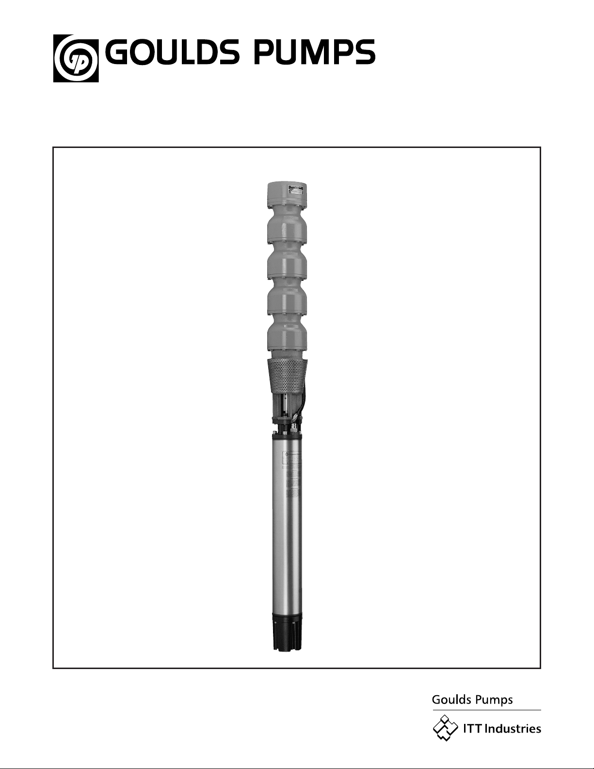
Model VS
Page 2

2
Page 3

IMPORTANT SAFETY NOTICE
To: Our Valued Customers
User safety is a major focus in the design of our products. Following the precautions outlined in this
manual will minimize your risk of injury.
ITT Goulds pumps will provide safe, trouble-free service when properly installed, maintained, and
operated.
Safe installation, operation, and maintenance of ITT Goulds Pumps equipment are an essential end user
responsibility. This Pump Safety Manual identifies specific safety risks that must be considered at all
times during product life. Understanding and adhering to these safety warnings is mandatory to ensure
personnel, property, and/or the environment will not be harmed. Adherence to these warnings alone,
however, is not sufficient — it is anticipated that the end user will also comply with industry and corporate
safety standards. Identifying and eliminating unsafe installation, operating and maintenance practices is
the responsibility of all individuals involved in the installation, operation, and maintenance of industrial
equipment.
Please take the time to review and understand the safe installation, operation, and maintenance guidelines
outlined in this Pump Safety Manual and the Instruction, Operation, and Maintenance (IOM) manual.
Current manuals are available at
your nearest Goulds Pumps sales representative.
www.gouldspumps.com/literature_ioms.html or by contacting
These manuals must be read and understood before installation and star t-up.
For additional information, contact your nearest Goulds Pumps sales representative or visit our Web site at
www.gouldspumps.com.
S-1
Page 4

SAFETY WARNINGS
Specific to pumping equipment, significant risks bear reinforcement above and beyond normal safety precautions.
WARNING
A pump is a pressure vessel with rotating parts that can be hazard o us. An y press ure vessel can explode,
rupture, or discharge its contents if sufficiently ove r press u r i zed causi n g deat h, personal injury, property
damage, and/or damage to the environment. All necessary measures must be taken to ensure over
pressurization does not occur.
WARNING
Operation of any pumping system with a blocked suction and discharge must be avoided in all cases.
Operation, even for a brief period under these conditions, can cause superheating of enclosed pumpage and
result in a violent explosion. All necessary measures must be taken by the end user to ensure this condition is
avoided.
WARNING
The pump may handle hazardous and/or toxic fluids. Care must be taken to identify the contents of the pump
and eliminate the possibility of exposure, particularly if hazardous and/or toxic. Potential hazards include, but
are not limited to, high temperature, flammable, acidic, caustic, explosive, and other risks.
WARNING
Pumping equipment Instruction, Operation, and Maintenance manuals clearly identify accepted methods for
disassembling pumping units. These methods must be adhered to. Specifically, applying heat to impellers
and/or impeller retaining devices to aid in their removal is strictly forbidden. Trapped liquid can rapidly
expand and result in a violent explosion and injury.
ITT Goulds Pumps will not accept responsibility for physical injury, damage, or delays caused by a failure to
observe the instructions for installation, operation, and maintenance contained in this Pump Safety Manual or the
current IOM available at www.gouldspumps.com/literature.
S-2
Page 5

SAFETY
DEFINITIONS
Throughout this manual the words WARNING, CAUTION, ELECTRICAL, and ATEX are used to indicate
where special operator attention is required.
Observe all Cautions and Warnings highlighted in this Pump Safety Manual and the IOM provided with
your equipment.
WARNING
Indicates a hazardous situation which, if not avoided, could result in death or serious injury.
Example:
Pump shall never be operated without coupling guard installed correctly.
CAUTION
Indicates a hazardous situation which, if not avoi ded, could result in minor or moderate injury.
Example: Throttling flow from the suction side may cause cavitation and pump damage.
ELECTRICAL HAZARD
Indicates the possibility of electrical risks if directions are not followed.
Example: Lock out driver power to prevent electric shock, accidental start-up, and physical injury.
When installed in potentially explosive atmospheres, the instructions that follow the Ex symbol must be
followed. Personal injury and/or equipment damage may occur if these instructions are not followed. If there
is any question regarding these requirements or if the equipment is to be modified, please contact an ITT
Goulds Pumps representative before proceeding.
Example:
parts, resulting in a spark and heat generation.
Improper impeller adjustment could cause contact between the rotating and stationary
S-3
Page 6

GENERAL PRECAUTIONS
WARNING
A pump is a pressure vessel with rotating parts that can be hazardous. Hazardous fluids may be contained by the
pump including high temperature, flammable, acidic, caustic, explosive, and other risks. Operators and
maintenance personnel must realize this and follow safety measures. Personal injuries will result if procedures
outlined in this manual are not followed. ITT Goulds Pumps will not accept responsibility for physical injury,
damage or delays caused by a failure to observe the instructions in this manual and the IOM provided with your
equipment.
WARNING
WARNING
General Precautions
NEVER use heat to disassemble pump due to risk of explosion from tapped liquid.
NEVER APPLY HEAT TO REMOVE IMPELLER. It may explode due to
trapped liquid.
WARNING
WARNING
WARNING
WARNING
WARNING
WARNING
WARNING
WARNING
WARNING
NEVER operate pump without safety devices installed.
NEVER operate pump without coupling guard correctly installed.
NEVER run pump below recommended minimum flow when dry, or without
prime.
ALWAYS lock out power to the driver befo re per fo rming pump maintenance.
NEVER operate pump with discharge valve closed.
NEVER operate pump with suction valve closed.
DO NOT change service application without approval of an authorized ITT
Goulds Pumps representative.
Safety Apparel:
Insulated work gloves when handling hot bearings or using bearing heater
Heavy work gloves when handling parts with shar p ed ges, especially
impellers
Safety glasses (with side shields) for eye protection
Steel-toed shoes for foot protection when handling parts, heavy tools, etc.
Other personal protective equipment to protect against hazardous/toxic fluids
Receiving:
Assembled pumping units and their components are heavy. Failure to properly lift
and support equipment can result in serious physical injury and/or equipment
damage. Lift equipment only at specifically identified lifting points or as
instructed in the current IOM. Current manuals are available at
www.gouldspumps.com/literature_ioms.html or from your local ITT Goulds
Pumps sales representative. Note: Lifting devices (eyebolts, slings, spreaders, etc.)
must be rated, selected, and used for the entire load being lifted.
Alignment:
WARNING
Shaft alignment procedures must be followed to prevent catastrophic failure of
drive components or unintended contact of rotating parts. Follow coupling
manufacturer’s coupling installation and operation procedures.
S-4
Page 7

WARNING
CAUTION
General Precautions
Before beginning any alignment procedure, make sure driver power is locked out.
Failure to lock out driver power will result in serious physical injury.
Piping:
Never draw piping into place by forcing at the flan ged con necti on s of t he pump.
This may impose dangerous strains on the unit and cause misalignment between
pump and driver. Pipe strain will adversely effect the operation of the pump
resulting in physical injury and damage to the equipment.
WARNING
WARNING
WARNING
WARNING
WARNING
WARNING
WARNING
WARNING
WARNING
WARNING
WARNING
CAUTION
CAUTION
WARNING
Flanged Connections:
Use only fasteners of the proper size and material.
Replace all corroded fasteners.
Ensure all fasteners are properly tightened and there are no missing fasteners.
Startup and Operation:
When installing in a potentially explosive environment, please ensure that the
motor is properly certified.
Operating pump in reverse rotation may result in contact of metal parts, heat
generation, and breach of containment.
Lock out driver power to prevent accidental start-up and physical injury.
The impeller clearance setting procedure must be followed. Improperly setting
the clearance or not following any of the proper procedures can result in sparks,
unexpected heat generation and equipment damage.
If using a cartridge mechanical seal, the centering clips must be installed and set
screws loosened prior to setting impeller clearance. Failure to do so could result
in sparks, heat generation, and mechanical seal damage.
The coupling used in an ATEX classified environment must be properly certified
and must be constructed from a non-sparking material.
Never operate a pump without coupling guard properly installed. Personal injury
will occur if pump is run without coupling guard.
Make sure to properly lubricate the bearings. Failure to do so may result in excess
heat generation, sparks, and / or premature failure.
The mechanical seal used in an ATEX classified environment must be properly
certified. Prior to start up, ensure all points of potential leakage of process fluid to
the work environment are closed.
Never operate the pump without liquid supplied to mechanical seal. Running a
mechanical seal dry, even for a few seconds, can cause seal damage and must be
avoided. Physical injury can occur if mechanical seal fails.
Never attempt to replace packing until the driver is properly locked out and the
coupling spacer is removed.
WARNING
WARNING
S-5
Dynamic seals are not allowed in an ATEX classified environment.
DO NOT operate pump below minimum rated flows or with suction and/or
discharge valve closed. These conditions may create an explosive hazard due to
vaporization of pumpage and can quickly lead to pump failure and physical injury.
Page 8

WARNING
WARNING
WARNING
WARNING
WARNING
CAUTION
CAUTION
WARNING
CAUTION
CAUTION
General Precautions
Ensure pump is isolated from system and pressure is relieved before
disassembling pump, removing plu gs, ope ni n g vent or drain valves, or
disconnecting piping.
Shutdown, Disassembly, and Reassembly:
Pump components can be heavy. Proper methods of lifting must be employed to
avoid physical injury and/or equipment damage. Steel toed shoes must be worn at
all times.
The pump may handle hazardous and/or toxic fluids. Observe proper
decontamination procedures. Proper personal protective equipment should be
worn. Precautions must be taken to prevent physical injury. Pumpage must be
handled and disposed of in conformance with applicable environmental
regulations.
Operator must be aware of pumpage and safety precautions to prevent physical
injury.
Lock out driver power to prevent accidental startup and physical injury.
Allow all system and pump components to cool before handling them to prevent
physical injury.
If pump is a Model NM3171, NM3196, 3198, 3298, V3298, SP3298, 4150, 4550,
or 3107, there may be a risk of static electric discharge from plastic parts that are
not properly grounded. If pumped fluid is non-conductive, pump should be
drained and flushed with a conductive fluid under conditions that will not allow
for a spark to be released to the atmosphere.
Never apply heat to remove an impeller. The use of heat may cause an explosion
due to trapped fluid, resulting in severe physical injury and property damage.
Wear heavy work gloves when handling impellers as sharp edges may cause
physical injury.
Wear insulated gloves when using a bearing heater. Bearings will get hot and can
cause physical injury.
S-6
Page 9

ATEX CONSIDERATIONS and INTENDED USE
Special care must be taken in potentially explosive environments to ensure that the equipment is properly
maintained. This includes but is not limited to:
1. Monitoring the pump frame and liquid end temperature.
2. Maintaining proper bearing lubrication.
3. Ensuring that the pump is operated in the intended hydraulic range.
The ATEX conformance is only applicable when the pump unit is operated within its intended use. Operating,
installing or maintaining the pump unit in any way that is not covered in the Instruction, Operation, and
Maintenance manual (IOM) can cause serious personal injury or damage to the equipment. This includes any
modification to the equipment or use of parts not provided by ITT Goulds Pumps. If there is any question
regarding the intended use of the equipment, please contact an ITT Goulds represe ntative before proceeding.
Current IOMs are available at
Pumps Sales representative.
All pumping unit (pump, seal, coupling, motor and pump accessories) certified for use in an ATEX classified
environment, are identified by an ATEX tag secured to the pump or the baseplate on which it is mounted. A
typical tag would look like this:
www.gouldspumps.com/literature_ioms.html or from your local ITT Goulds
The CE and the Ex designate the ATEX compliance. The code directly below these symbols reads as follows:
II = Group 2
2 = Category 2
G/D = Gas and Dust present
T4 = Temperature class, can be T1 to T6 (see Table 1)
Table 1
Max permissible
surface temperature
Code
T1 842 (450) 700 (372)
T2 572 (300) 530 (277)
T3 392 (200) 350 (177)
T4 275 (135) 235 (113)
T5 212 (100) Option not available
T6 185 (85) Option not available
o
F (oC)
The code classification marked on the equipment must be in accordance with the specified area where the
equipment will be installed. If it is not, do not operate the equipment and contact your ITT Goulds Pumps sales
representative before proceeding.
Max permissible
liquid temperature
o
F (oC)
S-7
Page 10

PARTS
The use of genuine Goulds parts will provide the safest and
most reliable operation of your pump. ITT Goulds Pumps ISO
certification and quality control procedures ensure the parts are
manufactured to the highest quality and safety levels.
Please contact your local Goulds representative for details on
genuine Goulds parts.
S-8
Page 11

SECTION 1 – GENERAL
INFORMATION
1-1 INTRODUCTION
The design, materials and workmanship incorporated in the construction of Goulds submersible
turbine pumps makes them capable of giving long,
trouble-free service. The life and satisfactory service of any mechanical unit, however, is enhanced
and extended by correct application, proper installation, periodic inspection, and careful maintenance. This instruction manual was prepared to
assist the operators in understanding the construction and correct methods of installing, operating,
and maintaining these pumps.
Study thoroughly Sections 1 through 8 and keep
this manual handy for reference. Further information can be obtained by contacting Goulds Pumps
sales office or your local branch office.
WARNING
GOULDS PUMPS SHALL NOT BE LIABLE FOR
ANY DAMAGES OR DELAY CAUSED BY FAILURE
TO COMPLY WITH THE PROVISIONS OF THIS
INSTRUCTION MANUAL.
1-2 RECEIVING AND CHECKING
The pump shall be carefully supported prior to
unloading from the carrier. Handle all components
carefully. Inspection for damage of the shipping
crate shall be made prior to unpacking the pump.
After unpacking, visually inspect the pump and
check the following:
A. Contents of the pump assembly against
shipping list.
B. All components against damage.
Any shortages or damages should be immediately called to the attention of the local freight
agent of the carrier by which the shipment
arrived and proper notation made on the bill.
This shall prevent any controversy when a claim is
made and to facilitate prompt and satisfactory
adjustment.
1-3 MATERIALS AND EQUIPMENT
REQUIRED
The material and equipment necessary for installation of the pump will vary with the size of the pump
and the type of installation. The following discussion and list of standard tools and supplies is
therefore offered only as a guide.
A. BULK MATERIAL
Anti-galling lubricant, thread compound, lubrication oil, grease, petroleum based solvent.
B. HAND TOOLS
Pipe Wrenches, two chains tongs and
mechanic’s hand tools.
C. INSTRUMENTS
One megger, or similar instrument indicating
electrical resistance, clamp-on ammeter,
voltmeter and a good grade of pipe joint
compound should be available to facilitate
assembly and possible future disassembly.
D. INSTALLATION EQUIPMENT
Wooden friction blocks or steel clamps, steel
column lifting elevators of approved type and
of proper size for the column pipe, and cable
sling approximately 10 feet long of adequate
size for the loads involved.
Although portable derricks are sometimes
used, a properly designed pump setting rig is
recommended. It must be possible to erect
the crown block to a height so as to allow the
load hook to be raised about three feet higher
than the longest piece. The lifting device
must be of sufficient strength and rigidity to
raise the total weight of the unit safely.
CAUTION
REMEMBER – REGARDLESS OF THE TYPE
OF LIFTING EQUIPMENT, OR THE TYPE OF
PUMPING EQUIPMENT, THE PRIMARY RULE
IS: SAFETY FIRST.
SECTION 2 – STORAGE
2-1 STORAGE
Goulds Pumps carefully preserves and protects its
products for shipment. However, the effective life
of the preservatives applied at the factory can vary
from 3 to 18 months depending on the severity of
the environment in which the equipment is stored.
This section provides procedures for preparation
prior to storage and maintenance during storage
of Goulds’ Pumps. These procedures are necessary to protect the precision parts of the pumps.
Specific procedures for storing motors should be
obtained from the motor manufacturer. This section is intended to be of general assistance to
users of Goulds Pumps. It shall not modify,
amend, and/or otherwise alter the scope of Goulds
Pumps warranty in anyway whatsoever.
3
Page 12

2-2 STORAGE PREPARATION
Goulds’ submersible pumps require proper preparation for storage. The pump shall be considered
in storage when it has been delivered to the job
site and is awaiting installation. If a pump has
been installed, but is not in regular operation, such
as seasonal shutdown or an extended period of
time, it is suggested that the pump be operated for
at least 15 minutes every two weeks if possible.
2-3 RECOMMENDED STORAGE
PROCEDURES
A. Controlled storage facilities should be main-
tained at an even temperature 10°F or more
above the dew point with relative humidity
less than 50% and little or no dust. (If these
requirements cannot be met the pump is to
be considered in uncontrolled storage.)
B. For uncontrolled storage periods of six months
or less, the pump is to be inspected periodically
to insure that all preservatives are intact.
C. All pipe threads and flanged pipe covers are
to be sealed with tape.
D. The pump must not be stored closer than six
inches to the ground.
2-4 PREPARATIONS FOR UNCONTROLLED
LONG TERM STORAGE
Storage periods over six months require the preceding uncontrolled storage procedure plus the
following:
A. Inspect the assembly and re-coat periodically
to prevent corrosion.
B. Place ten pounds of moisture absorbing des-
iccant or five pounds of vapor phase inhibitor
crystals near the center of the pump. If the
pump is assembled, place an additional one
pound in the discharge nozzle securely fastened to the discharge flange.
C. Install a moisture indicator near the perimeter
of the pump. Cover the pump with 6 mils minimum thickness black polyethylene or equal
and seal it with tape. Provide a small ventilation hole approximately
1
/2 inch diameter.
D. Provide a roof or a shed shelter to protect
from direct exposure to the elements.
Fig. 3.1 Typical Submersible Pump Installation
4
Page 13

SECTION 3 – GENERAL
DESCRIPTION
3-1 GENERAL DESCRIPTION
Goulds’ model VS pump is a submersible turbine
pump designed for maximum dependability. The
VS pump also features capacities from 100 to
3000 GPM and larger, heads to 1000 feet. See
Figure 3.1 for typical VS pump.
3-2 DRIVERS
Goulds furnishes only internationally recognized
motors designed for continuous operation under
any thrust which may develop throughout the performance curve. Impeller adjustment and type of
coupling, splined or clamped, is dependent on the
specific motor being used.
3-3 DISCHARGE
The discharge bowl provides an NPT or BSP
thread for connecting to the well head or the first
section of column pipe.
3-4 BOWL ASSEMBLY
The bowls are generally flanged construction for
accurate alignment and ease of assembly and disassembly. (Except D-line which have threaded
joints.) Impellers may be enclosed or open type.
Impeller position is set at factory. No field adjustment is required.
SECTION 4 – PREPARATION FOR
INSTALLATION
4-1 WELL REQUIREMENTS
A. The well should be developed with a test
pump prior to installing the submersible
pump. Test pumping the well serves several
purposes. It removes the excess sand
encountered during the initial pumping of the
well. Pumping sand or other abrasives with a
submersible pump will shorten the life of the
pump and can void the warranty.
CAUTION
DO NOT INSTALL THE UNIT WITH THE MOTOR IN
THE MUD, SAND OR RESTING ON THE BOTTOM
OF THE WELL. IT IS IMPORTANT TO PREVENT
THE WELL FROM SANDING UP AT ANY TIME TO
THE POINT THAT THE MOTOR BECOMES EVEN
PARTIALLY BURIED.
B. The test pumping also provides a means of
determining the capacity and drawdown. The
well capacity should equal or exceed the
pump capacity. If the pump removes water at
a higher rate than the well produces, the
drawdown will be excessive and the pump
will cavitate or ‘starve’ resulting in damage to
the pump and motor.
C. The well must be deep enough so that the
pump suction is at least 10 ft below the
expected drawdown level. If the well screen
or water producing aquifer is above the
pumping level, the required submergence of
the pump suction would be over 20 ft.
CAUTION
NEVER INSTALL UNIT WITH THE BOTTOM OF THE
MOTOR CLOSER THAN FIVE FEET FROM THE
BOTTOM OF THE WELL.
D. The motor must always be immersed in flow-
ing water. The flow rate must be over 1
ft/sec. If the pump is set below the well
screen openings or other conditions exist that
caused the water to be supplied from above
the pump, a flow induce sleeve should be
used.
E. The inside diameter of the well casing must
be large enough to allow lowering the unit
into the well without damage to the power
cable, the splice between the power cable
and the motor leads. Many wells have more
than one size of casings installed and frequently the lower sections are smaller in
diameter than the upper casing.
F. The submersible pump/motor unit must be
operated in a straight portion of the well.
Exerted pressures can and will cause misalignment of bearings or coupling. When the
straightness of the well is not known, it is recommended to lower a test blank with the
same diameter and length as the pump/motor
assembly with electrical leads into the well to
the desired depth. If there is any doubt about
straightness, gaging and plotting are recommended.
4-2 PREPARING THE FOUNDATION
The foundation must be rigid, level, and of adequate strength to support the complete weight of
the pump, motor, column, plus the weight of the
liquid passing through it. It is recommended the
foundation be constructed of solid concrete, however, adequate beams or timbers may be used. A
common foundation consists of the following concrete mixture:
5
Page 14

A. One part cement
B. Two parts sand
C. Four parts gravel
D. With sufficient water to make a stiff mix
4-3 MOTOR AND CABLE CHECKS AND
PREPARATION
CAUTION
DO NOT USE MOTOR LEADS TO LIFT OR HAN-
DLE THE MOTOR. THE MOTOR LEADS ARE EASI-
LY DAMAGED. THEY SHOULD BE PROTECTED
AND HANDLED WITH CARE AT ALL TIMES.
A. MOTOR SERVICING
Consult the motor manual and perform any
pre-installation servicing that is required.
Some motors may require filling with oil or
water.
B. ASSEMBLE OF MOTOR TO PUMP
If the pump and motor have not already been
assembled, assemble per the instructions
given in Appendix A. For extra long units, it
may be more practical to assemble the pump
to the motor in the vertical position at the
installation site.
C. TESTING BEFORE SPLICING POWER
CABLE TO MOTOR LEADS
Perform the following tests before making the
splice between the motor leads and the drop
cable. Instructions for performing resistance
tests and evaluating the results are given in
Appendix C.
Motor Tests
• Measure the resistance between each motor
lead and ground with the motor submerged in
water. (See Appendix C)
• Measure the resistance of the motor windings.
(See appendix C) Record the values for future
reference.
• Secure the pump and motor with chain tongs to
resist torque. Energize the motor momentarily
(on and immediately off) to check the rotation.
WARNING
GROUND THE UNIT WHEN TESTING. FAILURE TO
GROUND THE UNIT PROPERLY CAN RESULT IN
SERIOUS OR FATAL SHOCK. ALSO,THE HIGH
STARTING TORQUE OF THE MOTOR WILL CAUSE
IT TO ‘KICK’WHEN POWER IS APPLIED. THE
UNIT SHOULD BE RESTRAINED SUFFICIENTLY
TO PREVENT DAMAGE TO THE EQUIPMENT OR
PERSONAL INJURY.
NOTE
ROTATION WILL BE COUNTERCLOCKWISE
WHEN VIEWED FROM THE DISCHARGED BOWL.
On three phase unit, if rotation is wrong, interchange
any two of the motor leads at the control panel.
CAUTION
CORRECT ROTATION IS OF EXTREME IMPOR-
TANCE. EXCESSIVE OVER-LOADS MAY BE
DEVELOPED UNDER OPERATING CONDITIONS
WITH REVERSE ROTATION.
Drop Cable Test
• Measure the resistance between the cable
conductors and ground with the cable submerged in water. (See Appendix C)
D. SPLICING POWER CABLE TO MOTOR LEADS
A waterproof splice must be made to connect
the power cable to the motor leads. A properly made splice will last the life of the pump.
An improperly made splice will become a
service problem. Make the splice per instructions supplied with the drop cable or per
instructions in the pump motor manual. The
splice should be located above the pump
bowl. It should be as compact as possible. A
compact splice is less likely to be damaged
as the pump is being lowered into the well.
(See Appendix B for instruction on splicing
the cable.)
E. TESTING AFTER SPLICING POWER CABLE
TO MOTOR LEAD
Perform the following test after making the splice,
but before lowering the pump into the well.
• Check that the splice is waterproof by
immersing it in a container of water for
approximately one hour and then taking
resistance readings between each cable conductor and the water. (See Appendix C)
• Measure the total resistance of the complete
drop cable and motor circuit to insure that a
good splice was made. Record the values for
future reference.
CAUTION
THE MINIMUM READING FOR EACH LEAD TO
GROUND SHOULD BE 50 MEGOHMS.
6
Page 15

SECTION 5 – INSTALLING
THE PUMP
5-1 Check the pump and motor shaft to make
sure they turn free before installation. For some
models, it may be necessary to remove the suction screen in order to check the shaft. Be sure to
re-install the suction screen.
5-2 Raise the bowl/motor assembly with the shipping skids still in place. Remove the shipping
skids, and lower assembly into the well, clamping
the bowl assembly near the top.
5-3 Attach the elevators to the bottom column
pipe immediately below the column coupling.
Hoist the column section into place above the well
and the top of the bowl assembly, providing a soft
board or pipe dolly for the end of the column pipe
to slide in on so that threads will not be damaged
while the section is being raised. Clean all
threads with thread lubricant. Thread the pipe into
the discharge bowl connection and make up tight,
using one set of chain tongs for back-up.
CAUTION
THE PUMP MOTOR WILL EXERT A TORQUE THAT
WILL TEND TO UNSCREW THREADED COLUMN
PIPE CONNECTIONS. FOR THIS REASON,
THREADED COLUMN JOINTS MUST BE TIGHTENED. Following table gives the normal amount
of thread engagement necessary to make a tight
joint for the NPT thread joint:
Pipe size Length of thread (in.) No. of threads
3" 1" 8
4" 1-1/8" 9
5" 1-1/4" 10
6" 1-5/16" 10-1/2
8" 1-7/16" 11-1/2
10" 1-5/8" 13
5-4 Install a cable clamp on each side of the cable
splice. (See Figure 3.1.) Be careful not to damage the cable. If an air line is to be installed, route
it beside the cable, making sure that it is not
pinched by the clamps. If there is any danger that
the splice will rub against the well casing during
installation, it should be protected by thick rubber
chaffing pads or by a steel shield. Check that the
grounding system is in place.
WARNING
FAILURE TO GROUND THE UNIT PROPERLY CAN
RESULT IN SERIOUS OR FATAL SHOCK. REFER
TO ELECTRICAL CODE REQUIREMENTS.
5-5 Slowly lower the unit into the well (or sump)
adding joints of column pipe as the unit is lowered.
Tighten each joint securely. See note above.
Remove slack from the power cable and attach a
cable clamp approximately every 20 feet. For
units with large heavy power cable, additional
cable clamp may be required to give additional
support. Line up the cable on one side of the
pump and maintain as much clearance as possible on that side when lowering the pump in the
well. BE EXTREMELY CAREFUL NOT TO
SCRAPE OR DAMAGE THE POWER CABLE,
CABLE SPLICE, OR GROUNDING SYSTEM
WHEN LOWERING THE PUMP. Hold the power
cable up away from the well casing as lowering
the pump into the casing.
5-6 If the pump does not have a built-in check
valve, a line check valve should be installed within
25 feet above the pump bowl assembly. For a
deep setting pump, a line check valve is recommended for every 200 ft of column pipe. However,
no check valve should be installed above the
pumping level.
5-7 As soon as the splice joint is submerged in
the water, take a resistance reading between the
power cable conductors and ground to assure that
the insulation and the cable or the splice was not
damaged during installation.
5-8 After the last piece of column pipe has been
installed, install the well head. Install a cable
clamp between the last column pipe coupling and
the well head base. (See Fig. 3.1.) Route the
power cable and grounding system through the
large threaded hole in the head base. Route the
air line (if used) through one of the smaller threaded holes in the head base. The remaining small
threaded hole is for connection of a well vent or
other accessories. All of these holes are threaded
with standard NPT or BSP pipe threads. If a gasket is required between the head base and its
mounting surface, the gasket should be placed on
the foundation prior to installing the well head.
5-9 After the well head has been properly tightened, carefully rotate the entire unit in the well
until the discharge flange is facing in the desired
direction. Push the unit to one side of the well,
providing the maximum clearance for the drop
cable when rotating the unit.
5-10 Slowly lower the well head onto its mounting surface. BE CAREFUL NOT TO DAMAGE
THE GROUNDING SYSTEM OR PINCH THE
POWER CABLE BETWEEN THE SURFACE
7
Page 16

PLATE AND THE WELL CASING. If a gasket or
other seating device is used, be sure that it is
aligned properly and that it is not damaged. Install
the mounting bolts.
5-11 Before connecting the power cable to the
control panel:
Take a resistance reading between the power
cable conductors and ground to assure that the
insulation on the cable or splice was not damaged
during installation. (See Appendix C)
Measure the resistance of the power cable and
motor circuit. (See Appendix C) Compare these
readings with those taken in Section 4 to assure
that the splice is still intact. Make the electrical
connection between the power cable and the control panel. It may be desirable to use a terminal
box at the well head to simplify the electrical work
required when the pump is pulled. Be sure that
the unit is grounded properly.
WARNING
FAILURE TO GROUND THE UNIT PROPERLY CAN
RESULT IN SERIOUS OR FATAL SHOCK. REFER
TO ELECTRICAL CODE REQUIREMENTS.
Be sure to connect the leads as they were marked
previously in the procedure.
SECTION 6 – STARTING THE PUMP
CAUTION
INITIAL START-UP AND TESTING MAY REQUIRE
STARTING AND STOPPING THE PUMP SEVERAL
TIMES. BE SURE TO ALLOW ADEQUATE COOL-
ING OFF PERIOD BETWEEN STARTS. CONSULT
THE MOTOR MANUAL. IF NO INFORMATION IS
GIVEN, A GOOD RULE-OF-THUMB IS TO ALLOW
A MINIMUM OF 15 MINUTES BETWEEN STARTS.
For initial start-up allow the water to be pumped
out onto the ground. A throttle valve in the discharge line is recommended. Position the throttle
valve approximately one-forth open for start-up of
the pump. This will prevent surging the well or the
pump during start-up.
If the pump has been in the well for several days
before the start-up, check the resistance between
the cable conductor and ground to assure that
water has not penetrated the splice or the cable
insulation. (See Section 4)
Clamp the tongs of a clamp-on type ammeter
around one power lead to the pump. Set the
ammeter on the maximum scale. After the motor
starts, it can be reset to a lower scale as desired.
Refer to the motor manual and determine the normal operating amps for the installed motor.
Start the pump and observe and record the current readings on each conductor of the power
lead. If the current exceeds the normal value
determined in the motor manual, stop the pump
immediately. A high current reading indicates that
something is wrong. Among the potential problems are:
• Incorrect pump rotation (3 phase only)
• Improper voltage
• Sand locked pump
• Improper cable size or leak in cable
• Mechanical damage
In any case, the problem must be corrected before
the pump can be operated.
On three phase units if water does not appear
within one minute (deeper settings may require
approximately one half minute per 100 ft setting)
the motor may be running backwards. Stop the
pump and interchange any two of the three cable
connections. If there is any doubt about the proper rotation, run the motor in one direction and then
the other. The rotation that gives the highest pressure and flow is always the correct one.
Check the voltage. The voltage when the pump is
running should be within 5% of the pump motor
nameplate voltage.
Open the throttle valve. If a flow meter is available, open the throttle valve to rated flow of the
pump. If sand appears in the water, throttle the
pump at approximately 80% of full flow until the
sand clears. If excessive noise develops, pressure fluctuates, or water appears foamy white, the
pump is probably cavitating and the flow should
be throttled until the noise diminishes, the pressure remains steady, and the water is clear.
On three phase units check for current unbalance.
Details of the current unbalance test are given in
the Appendix C. THE MAXIMUM ALLOWABLE
CURRENT UNBALANCE IS 5%. If the current
unbalance exceeds 5% after rolling the leads and
connecting them for the lowest unbalance, the
pump should be stopped and corrective action
taken. Current unbalance in excess of 5% can be
expected to cause excessive heating in the motor
and premature failure. Operation with a current
unbalance in excess of 5% will void the warranty.
8
Page 17

After the unit is operating properly, a performance
test should be considered. If a performance test is
conducted when the pump is new, subsequent tests
can be used to determine the degree of wear or
deterioration of the pump without removing it from
the well. After the unit has been in operation for
approximately one week, perform the routine tests.
SECTION 7 – PUMP DISASSEMBLY
AND REASSEMBLY
7-1 Clear a large area adjacent to the pump
as storage space for pump parts as they are
disassembled. If the pump has a long column,
arrange parallel timbers on the ground to support
the pump column horizontally. After disassembly
for repair or replacement of pump components,
reassemble in all cases in the reverse order of
disassembly.
NOTE
PUMP COMPONENTS SHOULD BE MATCH-
MARKED PRIOR TO DISASSEMBLY.
7-2 It is recommended that maintenance person-
nel become thoroughly familiar with the VS pump
before performing any removal of the components.
Consult the manufacturer’s instructions for
detailed disassembly information for the motor.
A. Remove the electrical connection at the con-
duit box and tag electrical leads at the motor.
WARNING
BEFORE OPENING THE CONDUIT BOX OF AN
ELECTRICAL MOTOR, BE SURE THE CURRENT
TO THE MOTOR IS SHUT OFF. SEVERE INJURY
TO PERSONNEL COULD RESULT IF CONTACT
WITH LIVE MOTOR LEADS IS MADE
LOCK OUT SHOULD BE INSTALLED BEFORE
ANY ELECTRICAL WORK IS PERFORMED
NOTE
MATCH-MARK PARTS IN SEQUENCE OF
DISASSEMBLY TO AID IN THE REASSEMBLY
PROCEDURE.
B. Disconnect the discharge piping from well head.
WARNING
DO NOT WORK UNDER A HEAVY SUSPENDED
OBJECT UNLESS THERE IS A POSITIVE SUP-
PORT UNDER IT WHICH WILL PROTECT PER-
SONNEL SHOULD A HOIST OR SLING FAIL.
7-3 PUMP DISASSEMBLY
In the following pump disassembly procedures
references are made to installation sections of
this manual, these sections will aid in the disassembly of the pump.
Fig 7.1 Bowl and Motor Assembly
9
Page 18

A. Disconnect well head and begin removal of
column sections. Refer to Section 5-7.
B. For removal of bowl/motor assembly, hoist
the bowl/motor assembly from the well, using
elevator clamps. Hoist in the same manner
as for the column. For the keyed motor shaft,
loosen the setscrews on the motor end of the
shaft coupling. Remove the motor lead from
the cable guard. Disassemble the bowl
assembly from the motor by removing the
connecting bolts at the flange joint. For the
short assembly laying the bowl/motor assembly on the ground to perform these works.
For the long or large size assembly, it is recommended to perform these works while the
assembly is in the vertical position. Refer to
Section 4-3. Proceed to disassemble the
bowl assembly as follows.
7-4 BOWL DISASSEMBLY
The bowl assembly shown in Figure 7.1 is composed of a discharge bowl (For the model with
built-in check valve, it would be column adapter),
intermediate bowl, impellers with taper collects,
motor adapter, bearings and pump shaft.
A. Begin disassembly by removing the cap-
screws that secure the top stage intermediate
bowl and the 2nd stage intermediate bowl
and slide the discharge and top intermediate
bowls off the pump shaft together. Remove
the thrust washer.
B. Pull shaft out as far as possible and strike
impeller hub utilizing a taperlock driver or
equivalent sliding along the pump shaft to
drive the impeller off the taperlock
(see Figure 7-2).
Fig. 7-2 Disassemble the Impeller
C. After impeller is freed, insert a screwdriver
into the taperlock to spread it, Slide taperlock
and impeller off the pump shaft.
D. Use the preceding procedures until entire turbine
bowl assembly is completely disassembled.
7-5 TURBINE BOWL – WEAR RINGS
REMOVAL (OPTIONAL)
A. Utilizing a diamond point chisel, cut two ‘V’
shape grooves on the bowl wear ring approximately 180 degrees apart. Use extreme care
not to damage the wear ring seat.
B. With a chisel or equal, knock the end of one
half of the ring in, and pry the ring out.
C. On special materials such as chrome steel,
set up the bowl in a lathe and machine the
wear ring off, use extreme care not to
machine or damage the ring seat.
7-6 TURBINE BOWL – IMPELLER WEAR
RING REMOVAL (OPTIONAL)
Set up impeller in a lathe and machine wear ring
out, use extreme care not to machine or damage
ring seat or impeller hub. Impeller wear ring may
also be removed by following steps A and B
paragraph 7-5.
7-7 BOWL BEARING REMOVAL
Utilizing an arbor press and a piece of pipe or
sleeve with outside diameter slightly smaller than
bowl bearing diameter press the bearing out.
7-8 INSPECTION AND REPLACEMENT
A. Clean all parts thoroughly with a suitable
cleaner.
B. Check bearing seats for deformation and
wear.
C. Check pump shaft for straightness and exces-
sive wear on bearing surfaces. Check
straightness of the pump shaft. The straightness should within 0.0005”/ft TIR.
D. Visually check impellers and bowls for cracks
and pitting. Check all bowl bearings for
excessive wear and corrosion.
7-9 TURBINE BOWL AND IMPELLER
WEAR RING INSTALLATION
(OPTIONAL)
Place chamfered face of bowl or impeller wear
ring towards the ring seat and press. Use an
arbor press or equal. Make sure ring is flush with
edge of wear ring seat.
10
TAPERLOCK DRIVER
DISASSEMBLY POSITION
SHAFT
IMPELLER
BOWL
Page 19

7-10 BOWL BEARING INSTALLATION
Press the bearing into all the bowls by using an
arbor press or equivalent. Press the bearing in
from the bottom end of the hub until the bottom
end of the bearing is flush with the bottom end of
the hub.
7-11 TURBINE BOWL WITH TAPERLOCK
– REASSEMBLY
A. Secure the submersible assembly jig to the
motor end of the motor adapter (See fig. 7-3).
Be sure to use the proper jig for the motor
frame size the bowl assembly is intended to
adapt to.
B. Put some grease in the suction bearing of the
motor adapter. Slide the shaft through the
bearing. Secure the shaft in place by locking
the shaft to the assembly jig with a special
long bolt or all thread and a hex nut.
(See Fig. 7-3)
Figure 7-3 Assembly Jig
C. Slip impeller over the shaft. Then slip taper-
lock over the shaft with smaller end towards
impeller. A screwdriver can be used to
spread the taperlock for ease in slipping over
the shaft.
D. Hold impeller firmly against the motor adapter
and drive the taperlock into place with the
taperlock driver. (See Figure 7-3) After the
impeller is secured in position, the top end of
the taperlock should be 1/8” above the
impeller hub.
Fig. 7-4 Install the Impeller
E. Put a little grease on the shaft where the
intermediate bearing will be. Slip intermediate bowl over the shaft and bolt or screw it
onto the motor adapter.
F. Place the next impeller over the shaft and
continue to assemble as explained above.
G. After assembling the last impeller, slide the
upthrust washer over the shaft before assembling the top intermediate.
H. Slide the discharge case and top intermediate
bowl over the shaft and bolt it to the 2nd
intermediate bowl. If the pump has built-in
check valve, install the check valve before
installing the discharge adapter.
I. When the bowl is completely assembled,
unlock the shaft and remove the assembly jig.
Rotate the shaft by hand to see whether it
rotates freely. Push the shaft all the way in
and then pull it all the way out to check the
lateral clearance. The lateral should be
between 0.187" to 0.250".
J. Install the square key in the keyway at the
motor end of the pump shaft. Slide the shaft
coupling over the shaft and secure it to the
key with two setscrews.
11
Page 20

12
SECTION 8 – TROUBLE SHOOTING CHART
In case of difficulties, refer to the chart to locate basic problems with the system. Once the problem is
located, refer to specific sections in this manual for details.
PROBABLE CAUSE
1 Motor overload protector trip
a. Incorrect control box.
b. Incorrect connections.
c. Faulty overload protector.
d. Low voltage.
e. Ambient temperature of control
box or starter too low.
f. Pump bound by foreign matter.
2. Blown fuse, broken or loose electric
connections.
3. Motor control box or starter not in
proper position.
4. Cable insulation damaged.
5. Splice may be open or grounded.
6. Faulty pressure switch.
7. Faulty liquid level control.
1. Line check valve backward.
2. Pump is air-bound.
3. Lift too high for the pump..
4. Suction screen or impeller plugged, or
pump in mud or sand.
5. Pump not submerged.
6. Well may contain excessive amounts
of air or gas.
7. Three-phase unit running backwards.
1. Lift too high for the pump.
2. Screen or impellers partly plugged.
3. Scaled or corroded discharge pipe or
leaks anywhere in system.
4. Well may contain excessive amounts of
air or gas.
5. Excess wear due to abrasives
6. Three-phase pump running backward.
1. Incorrect set.
2. Switch opening plugged.
3. Leaks anywhere in system.
4. Three-phase unit running backward.
1. Water-logged tank.
2. Check valve leaking.
3. Pressure switch out of adjustment.
4. Leaks in service line.
REMEDY
1. Allow motor to cool, overload will
automatically reset. Investigate cause
of overload.
a– e Have a qualified electrician inspect
and repair, as required
f. Pull the pump, examine and clean.
Adjust set depth as required.
2. Check fuses, relays or heater elements
for correct size capacitor and all
electrical connections.
3. Make sure box is in upright position.
4. Locate and repair as per instructions.
5. Check resistance between cable leads
with ohmmeter. If open or grounded, pull
pump and re-splice.
6. Repair or replace.
7. Check relay, wires and electrodes.
1. Reverse check valve.
2. Successively start and stop pump until
water flows normally.
3. Review performance requirement.
4. Pull the pump and clean, check well
depth. Raise setting if necessary.
5. Check water level. Lower pump if
permissible.
6. Start and stop pump several times. If
this does not remedy conditions, pump
may not be able to co-operate because
of too much gas in the well.
7. Reverse rotation.
1. Check rating.
2. Pull pump and clean.
3. Replace pipe and repair leaks.
4. Start and stop pump several times. If
this does not remedy conditions, pump
may not be able to co-operate because
of too much gas in the well.
5. Replace worn parts.
6. Reverse rotation.
1. Change settings.
2. Clean opening or install new switch.
3. Repair leaks.
4. Reverse rotation.
1. Check tank for leaks (plug at top of tank
may be leaking air).
b. Be sure drain and ‘Y’ fittings are
functioning properly. Check operation of
snifter valve.
2. Replace check valve.
3. Readjust to correct setting or replace.
4. Locate and correct.
CONDITION
PUMP WILL NOT RUN
PUMP RUNS BUT
NO WATER
DELIVERED
REDUCED
CAPACITY OR
INSUFFICIENT
TANK PRESSURE
PRESSURE SWITCH
DOES NOT CUT OUT
PUMP STARTS TOO
FREQUENTLY
Page 21

APPENDIX A – ASSEMBLY OF
PUMP AND MOTOR
Most of the time, the pump and the motor are
shipped separately in two different boxes. They
need to be assembled together in the field prior to
being installed in the well. For the short pump
(lease than 5 stages), the motor and pump may
be assembled together on the ground horizontally.
If the pump is over 6 stages long, it is recommended to assemble them in the vertical position.
1. Check that the pump shaft and the motor
shaft turn freely.
2. Clean the flange faces and the registers on
the pump and the motor. Remove all burrs
from these areas. Clean the exposed portion
of the pump shaft and motor shaft. If the
pump is supplied with the coupling assembled
on the shaft, clean the inside of the motorend of the coupling.
3. Install the key on the motor shaft, if it is not
the splined shaft.
4. If the shaft coupling has setscrews in the
motor half of the coupling, loosen or remove
these setscrews.
5. Align the motor with the pump and slide the
motor shaft into the shaft coupling on the
pump until the shaft butts. Make sure the
motor shaft lifts the pump shaft by 1/8" to
1/4". (for enclosed impeller only) Be careful
not to damage the shaft, the coupling or the
key. Orient the motor so that the motor leads
are aligned with the notch provided in the
pump’s mounting flange. If the shaft coupling
has setscrews in the motor half the coupling,
install and tighten the setscrews.
6. Install and tighten the mounting bolts (or capscrews) on the flange.
7. Untie the cableguard on the pump and reassemble it with the motor leads under the
cableguard to prevent damaging the leads
when lower the pump into the well.
Appendix B – SPLICING POWER
CABLE TO MOTOR LEADS
A waterproof splice must be made to connect the
power cable to the motor leads. A properly made
splice will last the life of the pump. An improperly
made splice will become a service problem. In the
market, there are different materials and methods
to make water proof cable splices.
For example: by waterproof tapes
by resin castings
by heat shrink tubes
All of these system are well-known and fieldproven for many years. It is installer’s decision to
choose one of the systems available. Following
are the procedures for waterproof tapes and resin
castings splices:
Taped Cable Splice:
1. Strip the insulation of each conductor of the
power cable back enough to allow the conductor to extend half way through a sleeve
type connector. Crimp connector to the conductor. Strip the insulation of the motor lead
same as the power cable. Fit it into the connector and butt against cable end. Crimp
connector as before. Pull on wire to make
sure connector is firmly crimped to both the
motor lead and the power cable. Scrape the
insulation to move any loose bits of tape or
thread and roughen surface. Thoroughly
clean surface with solvent. This will insure a
watertight splice.
2. Tape individual joints with rubber electrical tape
start at the center of the connector, and tape 2
inches past the end of conductor insulation
end. Stretching tape about 10% while taping.
Overlap tapes about one half of tape width.
Make two layers. The end of 2nd layer should
be 2 inches beyond the end of the first layer.
3. Tape over the rubber electrical tape with #33
Scotch electrical tape or equivalent, using two
layers as in step #2 and making each layer
overlap the end of the preceding layer by
2 inches.
Cast Cable Splice:
1. To prepare the 3-conductor power cable for
splicing, insert a sharp knife blade between
the cable jacket and lead insulation and strip
the jacket back 2.5” from the end. Taking care
not to cut the lead insulation. Strip the cambric wrapping (if any) off the conductors and
strip back rubber insulation 5/8” from the end.
Assemble the cable connectors and crimp
them in place using a crimping tool.
2. Cut off the motor leads to equal length. Clean
off the ends of the leads for about a foot,
using a cloth wet with gasoline or solvent.
Clean the end of the power cable also. Insert
13
Page 22

the three motor leads into the corresponding
holes in the bottom of the rubber casing and
push them several inches out the top. Crimp
the motor leads into the corresponding connectors, crimping the center one first. Bend
the cables into line with the holes in the casing
and slip the casing up until the connectors are
inside the holes and about
1
/
4" from the top.
3. Mix the resin as directed. Cut off a corner of
the bag and squeeze all of the resin into casing. With the roll of tape on hand, fold the
bag, and tape the top of the bag snugly to the
power cable until the resin runs out over the
top. This will assure maximum coverage of
the resin and minimum size of the finished
splice. When the resin is firm to touch, the
splice may be immersed for testing.
In case of splicing cables of a six-lead motor
for y-delta starting, be sure that the extension
cable continue with the same lead colors and
phase designation as original motor leads.
This will ease up above ground connection to
the Y-Delta panel or an external delta connection for DOL start.
APPENDIX C – ELECTRICAL TESTS
1. MEASURING INSULATION
RESISTANCE (GROUND TEST)
The condition of the insulation around a conductor
can be determined by measuring the electrical
resistance between the conductor and ground.
This measurement can be made with a meggar or
an ohm-meter. The value is stated in ohms or
megohms (ohms x 1,000,000). High ohm values
indicate good insulation.
The basic procedure for measuring insulation
resistance is given below:
a. Turn off all power and disconnect the leads to
be tested from the electrical panel. Lock out
the panel.
WARNING
FAILURE TO TURN OFF THE POWER WILL
DAMAGE THE METER AND CAN CAUSE
SERIOUS OR FATAL SHOCK.
Failure to disconnect the leads can result in false
readings.
b. Set the meter selector knob to RX 100K or
RX 100,000 (some meters may not have RX
100K in which case EX 10K or EX 10,000
scale can be used). Clip the meter leads
together and adjust the meter to zero.
c. Unclip the leads and attach one of the meter
leads to the one of power cable leads or
motor leads. The other meter to the ground.
d. Do not touch any bare wires or allow bare
wires to come in contact with the ground or
metal. False readings will result.
e. If the meter needle is at either extreme end of
the scale, a more accurate reading can be
obtained by switching the selector switch to
another scale. Re-zero the meter each time
the selector switch is moved.
The readings obtained from power cables and
motor leads should be within the range specified
in Table C.1. Low readings indicate that the motor
windings are grounded or that the cable or splice
insulation is damaged. If low or marginal readings
are obtained on a new installation the problem
should be corrected before proceeding with the
installation.
2. MEASURING RESISTANCE
BETWEEN LEADS (MOTOR
WINDING RESISTANCE)
The general conditions of motor windings can be
determined by measuring the resistance of the
motor windings (i.e. the resistance between the
motor leads) and comparing the measured resistance with values given in the motor manual. The
resistance is measured with an ohm-meter and
the value is stated in ohms.
The basic procedure for measuring motor winding
resistance is given below.
a. Turn off the power and disconnect the leads to
be tested from the panel. Lock out the panel.
WARNING
FAILURE TO TURN OFF THE POWER WILL
DAMAGE THE METER AND CAN CAUSE SERIOUS
OR FATAL ELECTRICAL SHOCK.
Failure to disconnect the leads can result in false
readings.
b. Set the meter selector knob to ‘Rx 1’. Clip the
meter leads together and adjust the meter to zero.
c. Unclip the meter leads and attach them to the
motor leads.
Resistance measured between the motor leads
prior to splicing the power cable to the motor leads
should be within the motor winding resistance
limits specified in the motor manual.
14
Page 23

15
Resistance measured between the power cable
leads after splicing the power cable to the motor
leads will indicate the resistance of the power
cable plus the motor windings. The motor winding
resistance is obtained by the formula below. The
calculated value should be within the limits specified in the motor manual.
Motor Winding = Reading taken - Cable resistance
Resistance = at Power Cable - from Table 2
A higher winding resistance than shown in the
motor manual indicates a possible burned (open)
winding, an open cable, a loose connection, or the
wrong motor (different HP or voltage than readings
being referenced).
A considerably lower winding resistance than
shown in the motor manual indicates a possible
shorted (burned together) winding or the wrong
motor.
Unequal resistance between the windings on a
three phase motor indicates a burned winding or a
faulty connection.
TABLE C. 1 – NORMAL INSULATION RESISTANCE VALUES BETWEEN ALL LEGS AND GROUND
Insulation resistance does not vary with rating. Motors of all HP, voltage, and phase rating have the same
insulation resistance ranges.
METER READING
R x 100K R x 10K
CONDITION OF MOTORS AND LEADS OHMS MEGOHMS or or
R x 100,000 R x 10,000
Scale Scale
BENCH TESTS
• A new motor (without drop cable). 20,000,000 + 20+ 200+ 2000 + or 2K +
• A used motor which can be reinstalled 10,000,000 + 10+ 100+ 1000 + or 1 K +
in the well.
• Cable splice after immersion for one 2,000,000+ 2+ 20+ 200+
hour in water.
WELL TESTS Ohm readings are for drop
cable plus motor.
• A new motor or used motor in good 2,000,000+ 2+ 20+ 200+
condition.
• A motor in reasonably good condition. 500,000- 0.5-2.0 5-20 50-200
2,000,000
• A motor which may have been
damaged by lightning or with 0.02-0.5 0.2-5 2-50
damaged leads. Do not pull the pump 20,000-500,000
for this reason.
• A motor which definitely has been
damaged or with damaged cable. 0.01-0.02 0.1-0.2 1-2
The pump should be pulled and 10,000-20,000
repairs made to the cable or the motor
replaced. The motor will not fail for
this reason alone, but will probably
not operate for long.
• A motor which has failed or with
completely destroyed cable insulation. 0-0.01 0-0.1 0-1
The pump must be pulled and the Less than 10,000
cable repaired or the motor replaced.
+ Indicates that the reading should be the value shown or greater. Higher readings indicate better insulation.
Page 24

16
The values below are for copper conductors. If aluminum conductor drop cable is used, the resistance
will be higher for each foot of cable of the same size.
To determine the actual resistance of aluminum drop
cable, divide the ohm readings from this chart by
0.61. This chart shows total resistance of cable from
control box to motor and back.
TABLE C. 2 – POWER CABLE RESISTANCE
Page 25

17
3. CURRENT UNBALANCE TEST:
For three phase units, after correct rotation has
been established, check the current in each of the
three motor leads and calculate the current unbalance as explained below. If the current unbalance
is 2% or less, leave the leads as connected. If the
current unbalance is over 2%, current readings
should be checked on each leg using one of three
possible hook-ups indicated in the Table below.
Roll the motor leads across the starter in the same
direction to prevent motor rotation reversal. This
procedure is commonly known as “rolling the
leads”. THE HOOKUP THAT RESULTS IN THE
LOWEST PERCENT CURRENT UNBALANCE
SHOULD BE USED FOR THE FINAL CONNECTION OF THE POWER LEADS.
b. Current unbalance is determined by measur-
ing the amperage of each of the three legs
and then calculating the percent current
unbalance using the formula below. This calculation must be performed using each of the
three hookups shown.
Percent Current Unbalance =
Maximum current difference in
any leg from average current
Average current
x
100
Measure current in
each leg.
Add leg currents to
determine total
current.
Calculate average leg
current.
Determine maximum
difference of any one
leg from the average.
Calculate percent
unbalance using
formula above.
Sample Calculation
T1 L1 51 amps
T2 L2 46 amps
T3 L3 53 amps
=======
150 amps
÷ 3
=======
50 amps
51 – 50 = 1
50 – 46 = 4 max
53 – 50 = 3
x 100 = 8%
4
50
T1 L1 ________
T2 L2 ________
T3 L3 ________
=======
___ - ___ = ___
___ - ___ = ___
___ - ___ = ___
___ x 100 = % ___ x 100 = % ___ x 100 = %
T3 L1 ________
T1 L2 ________
T2 L3 ________
÷3
=======
___ - ___ = ___
___ - ___ = ___
___ - ___ = ___
T2 L1 ________
T3 L2 ________
T1 L3 ________
÷3
=======
___ - ___ = ___
___ - ___ = ___
___ - ___ = ___
÷3
Page 26

18
c. THE CURRENT UNBALANCE BETWEEN
LEGS SHOULD NOT EXCEED 5% at service
factor load or 10% at rated input load. If the
unbalance cannot be corrected by rolling
leads, the source of the unbalance must be
located and correct.
d. By observing where the furthest current reading
from the average is for each leg of each of the
hookups, the cause of the unbalance can be
determined. If the leg furthest from average is
always on the same power lead, this indicates
that most of the unbalance is from the power
source. If the leg furthest from average is
always on the same motor lead, the primary
source of unbalance is on the “motor side” of
the starter. In this instance, consider a damaged cable, leaking splices, poor connection, or
faulty motor winding.
Page 27

19
WARRANTY – Company warrants title to the
product(s) and, except as noted with respect to
items not of Company’s manufacturer, also warrants the product(s) on date of shipment to
Purchaser, to be of the kind and quality described
herein, and free of defects in workmanship and
material. THIS WARRANTY IS EXPRESSLY IN
LIEU OF ALL OTHER WARRANTIES, INCLUDING BUT NOT LIMITED TO IMPLIED WARRANTIES OF MERCHANT-ABILITY AND FITNESS, AND CONSTITUTES THE ONLY WARRANTY OF COMPANY WITH RESPECT TO THE
PRODUCT(S).
If within one year from date of initial operation, but
not more than 18 months from date of shipment
by Company of any item of product(s), Purchaser
discovers that such item was not as warranted
above and promptly notifies Company in writing
thereof, Company shall remedy such nonconformance by, at Company’s option, adjustment or
repair or replacement of the item and any affected
part of the product(s). Purchaser shall assume all
responsibility and expense for removal, reinstallation, and freight in connection with the foregoing
remedies. The same obligations and conditions
shall extend to replacement parts furnished by
Company hereunder. Company shall have the
right of disposal of parts replaced by it. Purchaser
agrees to notify Company, in writing, of any
apparent defects in design, material or workmanship, prior to performing any corrective action
back-chargeable to the Company. Purchaser shall
provide a detailed estimate for approval by the
Company.
ANY SEPARATE LISTED ITEM OF THE PRODUCT(S) WHICH IS NOT MANUFACTURED BY
THE COMPANY IS NOT WARRANTED BY COMPANY and shall be covered only by the express
warranty, if any, of the manufacturer thereof.
THIS STATES THE PURCHASER’S EXCLUSIVE
REMEDY AGAINST THE COMPANY AND ITS
SUPPLIERS RELATING TO THE PRODUCT(S),
WHETHER IN CONTRACT OR IN TORT OR
UNDER ANY OTHER LEGAL THEORY, AND
WHETHER ARISING OUT OF WARRANTIES,
REPRESENTATIONS, INSTRUCTIONS, INSTALLATIONS OR DEFECTS FROM ANY CAUSE.
Company and its suppliers shall have no obligation as to any products which has been
improperly stored or handled, or which has not
been operated or maintained according to
instructions in Company or supplier furnished
manuals.
LIMITATION OF LIABILITY - Neither Company
nor its suppliers shall be liable, whether in contract
or in tort or under any other legal theory, for loss of
use, revenue or profit, or for cost of capital or of
substitute use or performance, or for incidental,
indirect, or special or consequential damages, or
for any other loss or cost of similar type, or for
claims by Purchaser for damages of Purchaser’s
customers. Likewise, Company shall not under any
circumstances be liable for the fault, negligence, or
wrongful acts of Purchaser or Purchaser’s employees, or Purchaser other contractors or suppliers.
IN NO EVENT SHALL COMPANY BE LIABLE IN
EXCESS OF THE SALES PRICE OF THE
PART(S) OR PRODUCT FOUND DEFECTIVE.
Warranty
Page 28

Print in U.S.A.
1/03
Goulds Pumps and the ITT Engineered Blocks
symbol are registered trademarks and trade
names of ITT Industries.
www.goulds.com
 Loading...