

Page 1
SERVICE AND PARTS MANUAL
FOR ELECTRIC BAKE AND ROAST OVENS
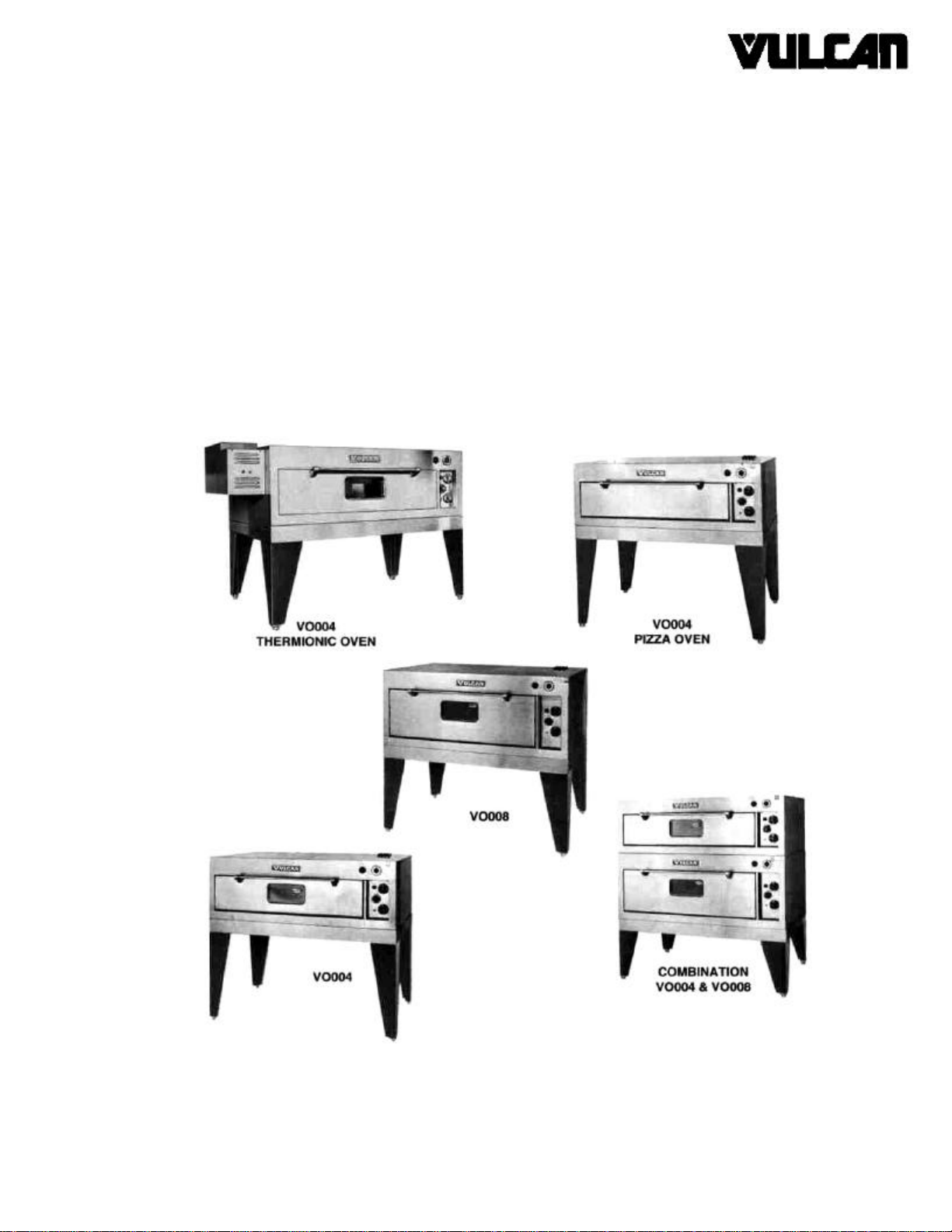
MODELS V0004 & V0008
FORM 30741 (9 -92) (Formerly 112637)
VULCAN-HART COMPANY, P.O. BOX 696, LOUISVILLE, KY 40201-0696, TEL. (502) 778-2791
Page 2

SERVICE AND PARTS MANUAL
ELECTRIC BAKE & ROAST OVENS
MODELS V0004 & V0008 INDEX
PLEASE KEEP THIS MANUAL FOR FUTURE REFERENCE
Your Vulcan oven is produced with quality
workmanship and material. Proper installation, usage
and maintenance will result in many years of
satisfactory performance.
DESCRIPTION PAGE
INDEX 3
TROUBLESHOOTING 4,5
CALIBRATING ELECTRIC CONTROLS 6
PARTS DESCRIPTION AND REPLACEMENT 7, 8
PARTS LIST 9-22
The manufacturer suggests that you thoroughly read this
entire manual and carefully follow all of the instructions
provided.
Page 3

TROUBLESHOOTING
The following is a guide for troubleshooting procedures and
covers some of the more common problems that may
develop. Servicing personnel need to become familiar with
the circuit and components in order to follow a logical
sequence of troubleshooting and to make repairs not
mentioned in this troubleshooting guide.
Remember that the two 3-heat switches control not only the
rate of temperature build-up in the oven, but the amount of
heat that is applied to their sections (top or bottom); therefore,
the operator can control the needed heat for a particular meal
by both its position inside the oven, as well as by varying the
3-heat switch setting.
The instruments required for troubleshooting are:
1. A.C voltmeter to measure line voltages up to 500 volts.
2. A.C. ammeter to measure line currents.
3. Accurate thermometer to measure temperature.
PROBLEM CORRECTIVE ACTION
No heat in any sections.
Check the main supply breaker or fuse.
No heat in one section only. Check voltage on the terminal block of the cool section. Follow 1 or 2
below.
1. If no voltage, check for loose or wrong connection of the interconnecting
leads.
2. If 208 volt, check, voltage between lead 3 and 6 or A3. Follow A or B
below.
A. If no voltage, check for bad connection to, or a tripped or failed
circuit breaker.
B. If 208 volt, measure voltage between 6 and 12 and between A3 and
11. If no voltage, check the thermostat. If 208 volt, check the
voltage between terminals 2 and 1 of the 3-heat switch (set the
switch on HI position). If no voltage, check for problem with the
switch. If 208 volt, check the elements for either open circuit or bad
connection.
Heat in bottom section only. Measure voltage between L2 and L3 terminals of the top 3-heat switch.
Follow 1 or 2 below.
1. If 208 volt, measure voltage between terminals 2 and 3 of the switch
(with switch set on HI position). Follow A or B below:
A. If no voltage, replace switch.
B. If 208 volt, check for opened elements or bad connection in leads
17,18,19.
2. If no voltage, check the thermostat and supply voltage as outlined in NO
HEAT IN ONE SECTION ONLY above.
In the following table, the voltmeter is used to measure the
voltage between two phases on 208, 240 and 480 volts, and
between the phase and the neutral on 220/380 and 240/415
volt supplies. Do not measure the voltage with respect to the
chassis ground. For the sake of simplicity, the measured
voltage is referred to 208 volt, assuming that the supply is
208 volt. When the supply is 220, 240 or 480 volt, the
measured voltage should also be 220, 240, 480 volts. Refer
to the appropriate wiring diagram for reference.
The fact that the voltmeter indicates presence of voltage does
not mean that the current is flowing. To be sure of optimum
function, an ammeter sh ould be used to determine the exact
amount of current going through the elements. Check the
supply current going to X, Y, or Z terminals and compare it
with the required value shown on the wiring diagram or the
rating decal (attached to the breaker cover) for the particular
supply voltage and phase.
With the main power ON, 3-heat switches set at HI, and the
thermostat set at about 400°F:
Page 4
PROBLEM CORRECTIVE ACTION
Heat in top section only. Follow the same procedure for the bottom 3-heat switch as outlined in HEAT
Oven temperature not Recalibrate the thermostat, following the instructions in RECALIBRATING
No oven lights (all models Since the two 25 watt, 120 volt bulbs are connected in series to the 208-240
except pizza oven). volt supply, a problem with either bulb will result in no lights. Replace both
208 volt models: Check for problem with breakers or bad connections to
480 volt models: Measure voltage between leads 4 and 31.
bad connection to the terminal block.
IN BOTTOM SECTION ONLY above.
ELECTRIC CONTROLS in this manual.
bulbs with two good ones. Make sure the bulbs are tight inside the socket.
If still no light, measure the voltage between leads 4 and 8 going to the
switch.
If 208 volt, check for problem with switch or bad connections to the switch
and to the lamp sockets.
If no voltage, proceed as follows:
breakers.
1. If 230 volt, check for problem with the breaker.
2. If no voltage, measure voltage between lead 32 and the transformer
lead connected to the end terminal of the breaker.
A. If 480 volt, check for problem with transformer.
B. If no voltage, measure between leads 32 and 33 on the breaker
terminal. If 480 volt, the breaker is bad. If no voltage, check for
Page 5
CALIBRATING ELECTRIC CONTROLS
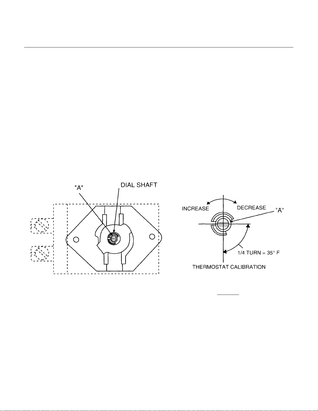
Fig.1
Robertshaw electric thermostats are adjusted at the factory
and calibrated on precision instruments to control
temperatures accurately. Adjustment or recalibration is not
needed unless the thermostat has been mishandled in transit,
or changed or abused while in service.
TO CHECK CALIBRATION
1. Use a Robertshaw test instrument or a good grade oven
thermometer and place thermocouple or thermometer in
center of oven.
2. With thermostat dial in the OFF position, make certain OFF
mark on the dial agrees with reference point of the bezel
or panel; misalignment will affect calibration. Then turn
the dial to a medium temperature setting.
4. After the control has cycled thermostatically three or more
TO CALIBRATE
5. Turn control to OFF position and remove dial.
6. With screwdriver, turn screw "A" clockwise to decrease and
7. Replace dial.
times, note the oven temperature when the electric unit
snaps off, and the oven temperature when it snaps on.
Recalibrate only if the average of these two temperature
readings varies more than ±20°F of the dial setting.
counterclockwise to increase the temperature. A 1/4 turn
of screw "A" causes a temperature shift of 35°F (Fig. 1).
3. Allow oven to heat until control snaps ON and OFF
thermostatically at least three times. This will allow oven
temperature to stabilize and eliminate possible error
resulting from initial oven temperature overshoot and/or
undershoot.
After calibration is made, allow oven to operate until
temperature has stabilized, then recheck to determine
whether or not the calibration has been corrected.
PL-501 119|
Page 6
PARTS DESCRIPTION AND REPLACEMENT
WARNING: DISCONNECT ELECTRICAL POWER SUPPLY
BEFORE SERVICING.
Reconnect the leads to the replaced component exactly as to
the original (refer to the wiring diagrams for each model).
SWITCH PANEL
Thermostat
A DPST cycling switch, with its normally closed contacts,
provides power to the two non-cycling 3-heat switches, which,
in turn, turns on the heating elements. Once the set
temperature is reached, the contacts open and the elements
are turned off. The thermostat used in pizza ovens has a
maximum temperature limit of 700°F. The thermostat used in
all other models has a limit of 500°F.
To replace the thermostat, remove the bulb from under the
mounting clips inside the oven. Pull out the capillary through
the hole on the right -hand oven wall, loosen the two mounting
screws of the thermostat, and remove it from the switch
panel.
To recalibrate the thermostat, follow the instructions in
CALIBRATING ELECTRIC CONTROLS in this manual.
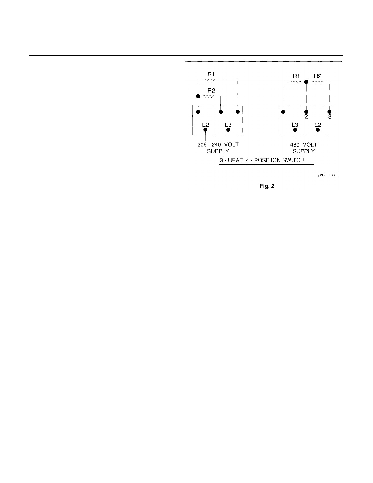
3-Heat Switch
A double-pole, 4-position sw itch connects the supply power at
its input (L2, L3 terminals) to the elements at its output
(terminals 1, 2, 3) in such a way as to provide full power
(elements connected in parallel) to about half of full power
(only one element connected) to about one-fourth of full
power (elements connected in series) as it rotates from HI to
MED to LO positions. At the OFF position, all connections are
opened. Therefore, the position of the 3-heat switch
determines the rate of temperature rise, while the thermostat
controls the temperature limit. The 3-heat switches used in
208-240 volt and 480 volt models, though physically looking
different, electrically are identical. The following diagrams
show the proper connection for each model:
HI position: L2 connects with 2
MED position: L2 connects with 2
LOW position: L2 connects with 3
OFF position: All connections open
To remove the switch, loosen the nut on the shaft and pull it
out from the back of the switch panel.
Signal Light
The light ON indicates that the thermostat contacts are
closed, providing power to the 3-heat switches. The light goes
off when the set temperature is reached. While maintaining at
set temperature, the light cycles on and off.
To replace the bulb, unscrew and remove the lens to reach
the bulb.
To replace the socket assembly, loosen and remove the nut in
the back of the switch panel, then pull the socket out from the
front.
L3 connects with 1 & 3
L3 connects with 1
L3 connects with 1
NOTE: On 480 volt models, make sure that a 300K ohm
resistor is added in series with the light.
Page 7
To replace bulbs, remove the four screws mounting the
window assembly to the oven wall.
NOTE: Make sure that the bulb is 25 watt and the
gasket is in good condition.
Element Assembly
2. 480 Volt Model
Remove the breaker closure in order to reach
the components.
A. Terminal Block — Used for field or
interconnecting supply leads. To replace,
remove the two mounting screws.
The inner and outer elements in the top or bottom
section of the oven are connected together by a jumper
strap on one end (common junction, connected to
terminal 2 of the 3-heat switch). The voltage and
wattage rating is stamped on each element (see wiring
diagrams for detail).
Replace the elements from inside the oven as follows:
1. Top Elements
Remove the element terminal cover and loosen the
bolts and nuts to disconnect the end straps from the
element terminals. Remove the retainers holding the
elements to the frame and slide the element out of
the frame assembly.
2. Bottom Elements
Remove the oven hearth by removing the three
slotted head bolts. Lift front of the hearth and pull it
out of the oven. To replace the elements, follow the
same procedure described in Item 1 above.
Connection Block Assembly
1. 208 and 240 Volt Models
Remove the breaker closure in order to reach the
components.
B. Porcelain Block — Used as a junction for
wires going to the oven lights.
C. Breaker — The coil of the relay trip breaker is
connected in series with the primary of the
control transformer, and the switches of the
breaker are connected in series with the
secondary winding of the transformer.
Overload in the coil of the breaker causes
the switch to trip open, turning off the
control circuit (secondary of the
transformer).
To replace, remove the two mounting screws.
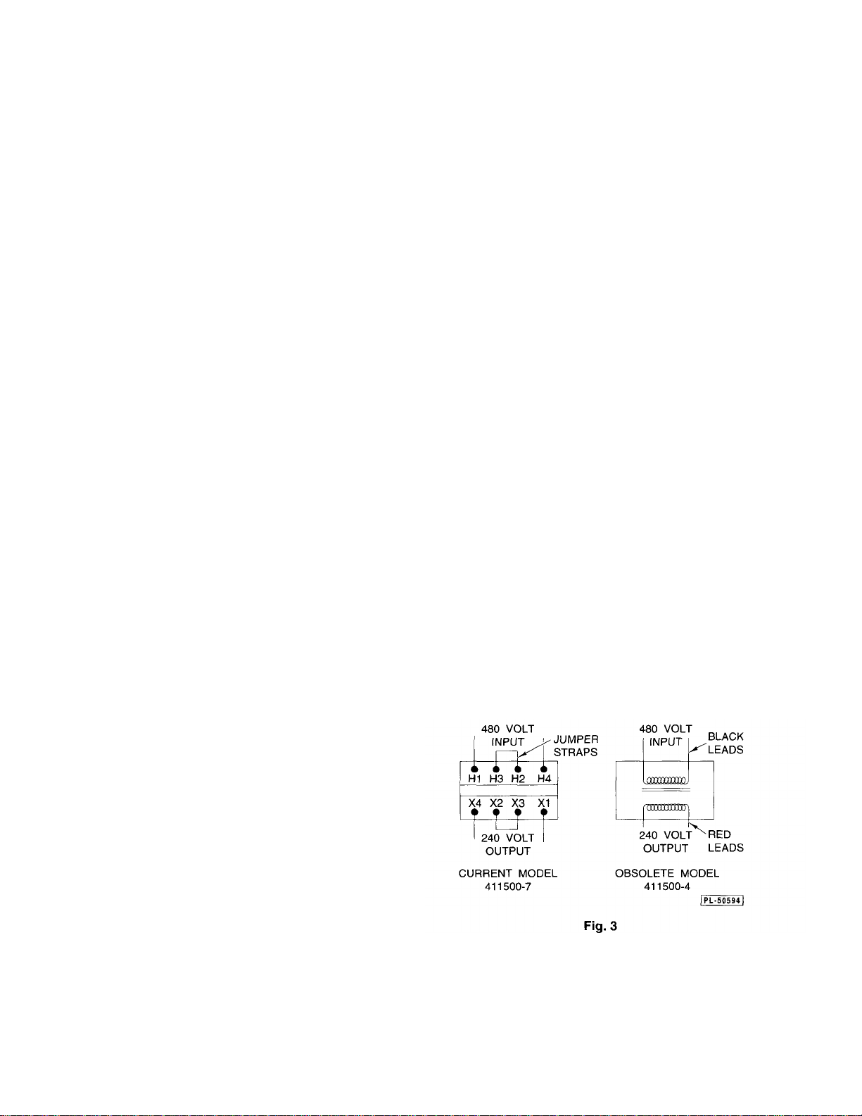
D. Transformer — The 460 to 230 volt, 200 VA
control transformer steps down the supply
voltage for the oven light circuit.
To replace, remove the four mounting screws.
NOTE: When replacing the transformer,
make sure that terminal H2 is connected to
H3 and terminal X2 to X3 by means of the
metal jumper strap or jumperwire lead.
ConnecttoH"! andH4 terminals (primary or
input) the 480 volt supply leads, and
connect to X1 and X4 terminals (sec ondary
or output) the 240 volt leads for the light
circuit. See the 480 volt wiring diagrams for
A. Terminal Block—Used for interconnecting or field
supply leads. To replace, remove the two
mounting screws.
B. Porcelain Block — Used as a junction for wires
going to the oven lights.
C. Breakers — The 15 amp. breakers protect the
lights and thermionic (fan) circuit. The 50 amp.
breakers protect the heating elements. To
replace, remove the two mounting screws.
detail.
Timer
Remove the knob and the lockwasher from outside the
oven. Remove the timer body from inside the control
compartment.
Page 8

REPLACEMENT PARTS LIST
REPLACEMENT PARTS ORDERING
The following information must accompany a replacements parts order or it cannot be filled.
A. Model and style or serial number.
B. Type of gas (natural or propane).
C. Voltage and phase.
D. Appliance finish, permafinish, stainless steel, etc. (if applicable to part to be replaced).
Use rating plate located on the front frame flange below the control panel to help you obtain the information listed above. This
plate will provide all the necessary information required by the service agency.
Parts may be ordered only from your authorized parts and service depot. For assistance in locating your nearest authorized parts
and service depot, refer to the enclosed directory.
ALL SERVICE PERSONNEL
WHEN SERVICING THIS EQUIPMENT, USE ONLY CONTROLS
ORIGINALLY SUPPLIED ON THIS EQUIPMENT BY VULCAN-HART
COMPANY. DO NOT SUBSTITUTE.
SUBSTITUTION OF CONTROLS AS STATED ABOVE WILL AUTOMATICALLY
VOID THIS WARRANTY AND THE CERTIFICATION ASSOCIATED WITH THIS
EQUIPMENT.
Page 9

CONTROL AND SWITCH PANEL ASSEMBLY — 460 VOLT USED
ON ALL V0004 & V0008 SERIES
ITEM
NUMBER DESCRIPTION NUMBER PER SECTION
1 Thermostat (Except Pizza Models) * 415119-G2 1
2 Thermostat Knob (Except Pizza Models) 500°F 415119-4 1
3 Thermostat Knob (Pizza Models Only) 700°F 415119-3 1
4 3-Heat Switch 419621-G1 2
5 3-Heat Switch. Knob 407727-2 2
6 Signal Light Assembly Including Bulb & Lens 417808-1 1
7 Toggle Swit ch (Except Pizza Models) 417812-1 1
8 Switch Panel Cover 420275 1
9 Switch Terminal Insulator 407802-1
10 Resistor (300 K) 417876-1 1
11 Switch Panel Assembly (V0004 Series) 420471 1
Thermostat (Pizza Models Only) * 415119-G3 1
Bulb Alone 417809-1 1
Switch Panel Assembly (V0008 Series) 420469 1
Plug Button (Pizza Models Only) (Not Shown) PB-004-26 1
PART QUANTITY
*Effective on models constructed after 10/72.
10
Page 10

CONTROL AND SWITCH PANEL ASSEMBLY — 208 OR 240 VOLT USED ON
ALL V0004 AND V0008 SERIES
ITEM
NUMBER DESCRIPTION NUMBER PER SECTION
1 Thermostat (Except Pizza Models) 415119-G2 1
2 Thermostat Knob (Except Pizza Models) 550°F 415119-4 1
3 Thermostat Knob (Pizza Models Only) 700°F 415119-5 1
4 3-Heat Switch * 419621-G1 2
5 3-Heat Switch Knob 407727-2 2
6 Signal Light Assembly Including Bulb & Lens 417808-1 1
7 Toggle Switch (Except Pizza Models) 417812-1 1
8 Switch Panel Cover 420275 1
9 Switch Panel Assembly (V0004 Series) 420471 1
Thermostat (Pizza Models Only) 415119-G3 1
Bulb Alone 417809-1 1
Switch Panel Assembly (V0008 Series) 420469 1
Plug Button (Pizza Models Only) (Not Shown) PB-004-26 1
PART QUANTITY
*Effective on models constructed after 10/72
Page 11

BLOWER MOTOR AND COVER DOOR ASSEMBLY USED
ON V0004 & V0008 THERMIONIC SERIES
ITEM
NUMBER DESCRIPTION NUMBER PER SECTION
115 Toggle Switch with Hardware 417812-1 1
156 Motor Assembly (115 & 480 Volt, 60 Cy.) 413048-2 1
156A Motor Assembly (240 Volt, 60 Cy.) 413048-1 1
156B Motor Assembly (220 Volt, 50 Cy.) 413048-3 1
157 Blower Support Assembly 409355-G1 1
167 Cover Door Assembly 408077-G1 1
168 Switch Guard 409077-1 1
169 Signal Light 406891-3 1
PART QUANTITY
•Starting with Serial Number 7742202.
12
Page 12

LAMP BOX ASSEMBLY USED ON ALL V0004 AND V0008 SERIES EXCEPT
PIZZA OVENS
ITEM
NUMBER DESCRIPTION
1 Lamp Window Assembly * 411175-G1 1
2 Lamp Box Gasket * 411206-1 1
3 Frosted Bulb (25 Watt)
4 Lamp Box
5 Lamp Socket
6 Lamp Cover Assembly
*Effective on models constructed after 4/73.
PART QUANTITY
NUMBER PER SECTION
BL-003-08 2
420272 1
417814-1 2
420269 1
Page 13

14
Page 14

DOOR MECHANISM ASSEMBLY AND OVEN DECK ASSEMBLY SINGLE
AND MULTIPLE UNITS USED ON ALL V0004 AND V0008 SERIES
ITEM
NUMBER DESCRIPTION NUMBER PER SECTION
87 Crank Support Assembly 408895-G1 1
88 Spacer (3/4" Pipe x 7/16" Long) 409240-2 1
90 Bearing 404629-1 3
91 Crank Support 408896-1 1
92 1/2-13 Hex Head Shoulder Bolt (2" Long) SC-090-01 1
99 3/8-16 Hex Head Shoulder Bolt (3/4 Long) 417860-1 1
100 Long Door Spring 406363-1 1
158 Short Door Spring 408980-1 1
159 Spring Support 408893-1 2
160 Eye Bolt (Closed) (V0004 Series) 402570-1 1
160A Eye Bolt (Open) (V0008 Series) 402570-3 2
161 Door Control Arm Assembly 419631-G1 1
162 Door Frame Assembly (V0004 Series) 420403 1
162A Door Frame Assembly (V0008 Series) 420404 1
Door Hinge Pin 417862-2 2
1/4-20 Hex Head Bolt (3/4 Long) SC-036-13 6
1/4-20 Lock Nut NS-044-14 8
Oven Door Assembly (V0004 — Except Pizza Ovens) 420480 1
Oven Door Assembly (V0008 Series) 420481 1
Oven Door Assembly (V0004 Pizza Ovens Only) 420482 1
Oven Door Handle Spacer (l 11/32" Long) 401534-2 2
Oven Door Handle 401847-2 1
Right-Hand Door Handle Post 404549-3 1
Left-Hand Door Handle Post 404549-4 1
Door Insulation (4 x 45 x 9 1/2) (V0004 Series) 420010 1
Door Insulation (4 x 45 x 131/2) (V0008 Series) 420010 1
Window (Except Pizza Ovens) 415653-1 1
Plug Button (7/8" Dia. for 11/16" Dia. Hole) PB-004-73 2
3/8-16 Round Head Bolt (1 1/4" Long) SC-120-22 2
10-24 Slotted Hex Head Bolt (3/4 Long) SC-110-31 4
Washer—Plain (1/2" O.D. x 3/16" I.D.) WS-003-03 4
10-24 Pan Head Tri-Roundular Bolt (3/8" Long) SD-024-1 27
Oven Deck Plate Assembly 420288 2
Oven Deck Plate (Optional With V0004 Pizza Ovens) 417022-1 2
PART QUANTITY
NOTE: Pizza Ovens Are Not Supplied With Windows Or Lights.
Page 15

TOP ELEMENT ASSEMBLY USED ON ALL
V0004 AND V0008 SERIES
ITEM
NUMBER DESCRIPTION
1 Element Frame Assembly * 420437 1
2 Outer Top Element (208 Volt) **• 410743-3 1
3 Inner Top Element (208 Volt) ** 410760-4 1
4 Jumper Strap * 420514 1
5 Rear Terminal Lead
6 Connector Cover
Top Element Assembly (208 Volt) * 412656-G1 1
Top Element Assembly (240 Volt) * 412656-G2 1
Top Element Assembly (480 Volt) * 412656-G3 1
Outer Top Element (240 Volt) *•* 410743-2 1
Outer Top Element (480 Volt) ** 410743-1 1
Inner Top Element (240 Volt) ** 410760-5 1
Inner Top Element (480 Volt) ** 410760-6 1
PART QUANTITY
NUMBER PER SECTION
420311 3
420441 1
* Effective on models constructed after 3/74.
** Effective on models constructed after 12/76
16
Page 16

BOTTOM ELEMENT ASSEMBLY USED ON ALL
V0004 AND V0008 SERIES
ITEM
NUMBER DESCRIPTION
1 Element Frame Assembly
2 Outer Bottom Element (208 Volt) * 410743-3 1
3 Inner Bottom Element (208 Volt) ** 410760-4 1
4 Jumper Strap * 420514 1
5 Rear Terminal Lead
Bottom Element Assembly (208 Volt) * 412657-G1 1
Bottom Element Assembly (240 Volt) * 412657-G2 1
Bottom Element Assembly (480 Volt) * 412657-G3 1
Outer Bottom Element (240 Volt) * 410743-2 1
Outer Bottom Element (480 Volt) * 410743-1 1
Inner Bottom Element (240 Volt) ** 410760-5 1
Inner Bottom Element (480 Volt) ** 410760-6 1
PART QUANTITY
NUMBER PER SECTION
420445 1
420311 3
Effective on models constructed after 3/74.
Effective on models constructed after 11/76.
Page 17

CONNECTION BLOCK ASSEMBLY - BOTTOM SECTION - 208 OR 240 VOLTS USED ON
ALL V0004 AND V0008 SERIES
ITEM
NUMBER DESCRIPTION NUMBER PER SECTION
1 Terminal Block 410472-8 1
2 Porcelain Block (Except Pizza Ovens) 414881-1 1
3 Breaker Support 412042-1 1
4 Breaker Cover (V0004 Series) 412043-1 1
4A Breaker Cover (V0008 Series) 412043-2 1
5 Closure and Support Angle (V0004 Series) 412044-1 1
5A Closure and Support Angle (V0008 Series) 412044-2 1
6 Breaker (50 Amp) 411501-14 1
7 Breaker (15 Amp) (Except Pizza Ovens, Excluding Thermionic 411501-13 2
Models)
PART QUANTITY
Page 18

CONNECTION BLOCK ASSEMBLY - UPPER SECTION - 208 OR 240 VOLTS USED ON
ALL V0004 AND V0008 SERIES
ITEM
NUMBER DESCRIPTION NUMBER PER SECTION
1 Terminal Block 410472-8 1
2 Porcelain Block (Except Pizza Ovens) 414881-1 1
3 Breaker Support 412042-1 1
4 Breaker Cover (V0004 Series) 412043-1 1
4A Breaker Cover (V0008 Series) 412043-2 1
5 Closure and Support Angle (V0004 Series) 412044-1 1
5A Closure and Support Angle (V0008 Series) 412044-2 1
6 Breaker Closure Plate 412048-1 1
7 Breaker (50 Amp) 411501-14 1
PART QUANTITY
Page 19

CONNECTION BLOCK ASSEMBLY - UPPER SECTIONS - 460 VOLT USED ON ALL V0004
AND V0008 SERIES (AND BOTTOM SECTION V0004 PIZZA OVEN WITHOUT THERMIONIC
FEATURE)
ITEM
NUMBER DESCRIPTION NUMBER PER SECTION
1 Terminal Block 410472-8 1
2 Porcelain Block (Except Pizza Ovens) 414881-1 1
3 Breaker Support 412042-1 1
4 Breaker Cover (V0004 Series) 412043-1 1
4A Breaker Cover (V0008 Series) 412043-2 1
5 Closure and Support Angle (V0004 Series) 412044-1 1
5A Closure and Support Angle (V0008 Series) 412044-2 1
6 Breaker Closure Plate 412048-1 1
PART QUANTITY
Page 20

CONNECTION BLOCK ASSEMBLY - BOTTOM OR SINGLE SECTION - 460 VOLT *USED ON ALL
V0004 AND V0008 SERIES WITH OR WITHOUT THERMIONIC FEATURE
ITEM
NUMBER DESCRIPTION NUMBER PER SECTION
1 Terminal Block 410472-8 1
2 Porcelain Block 414881-1 1
3 Breaker Support 412042-1 1
4 Breaker Cover (V0004 Series) 412043-1 1
4A Breaker Cover (V0008 Series) 412043-2 1
5 Closure and Support Angle (V0004 Series) 412044-1 1
5A Closure and Support Angle (V0008 Series) 412044-2 1
6 Breaker 411501-8 1
7 Transformer 460-230, 200VA 411500-7 1
8 Breaker Closure Plate 412048-1 1
PART QUANTITY
* Effective on models constructed after 10/72.
** Effective on models constructed after 5/75.
21
Page 21

DAMPER ROD ASSEMBLY USED ON ALL V0004
AND V0008 SERIES
ITEM
NUMBER DESCRIPTION NUMBER PER SECTION
122 Upper Damper Control Rod Assembly 407585-G1 1
123 Control Rod Assembly 407586-G1 1
124 Damper Assembly 407548-G1 1
125 Damper Clamp 407550-1 1
126 Support Bracket 407590-1 1
127 Damper Crank Connecting Link 407591-1 1
128 Knob Assembly 407545-1 1
129 Compression Spring 417810-1 2
10-24 Shoulder Bolt (V2" Long) 418623-1 2
10-24 Flexloc Nut NS-047-70 2
PART QUANTITY
 Loading...