

Page 1
SERVICE MANUAL
VMCS HEAVY DUTY ELECTRIC
GRIDDLE TOP
MODELS
VMCS-101
VMCS-102
VMCS-201
VMCS-202
- NOTICE -
This Manual is prepared for the use of trained Vulcan Service
Technicians and should not be used by those not properly
qualified.
This manual is not intended to be all encompassing. If you have
not attended a Vulcan Service School for this product, you should
read, in its entirety, the repair procedure you wish to perform to
determine if you have the necessary tools, instruments and skills
required to perform the procedure. Procedures for which you do
not have the necessary tools, instruments and skills should be
performed by a trained Vulcan Service Technician.
The reproduction, transfer, sale or other use of this Manual,
without the express written consent of Vulcan, is prohibited.
This manual has been provided to you by ITW Food Equipment
Group LLC ("ITW FEG") without charge and remains the property
of ITW FEG, and by accepting this manual you agree that you will
return it to ITW FEG promptly upon its request for such return at
any time in the future.
A product of Vulcan-Hart 3600 North Point Blvd Baltimore, MD 21222
F45571 (0316)
Page 2

VMCS HEAVY DUTY ELECTRIC GRIDDLE TOP
TABLE OF CONTENTS
GENERAL .................................................................................................. 3
INTRODUCTION ....................................................................................... 3
OPERATION AND FIELD INSTALLATION .............................................................. 3
MODELS ............................................................................................... 3
SPECIFICATIONS ...................................................................................... 3
TOOLS ................................................................................................. 3
REMOVAL AND REPLACEMENT OF PARTS ............................................................... 4
REMOVE CLAMSHELL FROM FRAME ................................................................. 4
TOP CONTROL BOX COVER .......................................................................... 6
POWER SWITCH ...................................................................................... 7
INDICATOR LIGHTS ................................................................................... 7
POWER CORD ......................................................................................... 8
HIGH LIMIT ............................................................................................ 8
CONTROL THERMOSTAT ............................................................................. 9
HEATING ELEMENTS ................................................................................ 11
ARM MECHANISM .................................................................................... 12
SERVICE PROCEDURES AND ADJUSTMENTS ........................................................... 14
GRIDDLE TOP MANUAL LIFT CHECK ................................................................ 14
PLATE GAP ADJUSTER .............................................................................. 14
THERMOSTAT TEST ................................................................................. 15
HEATING ELEMENT TEST ............................................................................ 15
ELECTRICAL OPERATION ................................................................................ 16
COMPONENT LOCATION ............................................................................. 16
COMPONENT FUNCTION ............................................................................ 16
WIRING DIAGRAM .................................................................................... 17
TROUBLESHOOTING ..................................................................................... 18
TROUBLESHOOTING ................................................................................. 18
© VULCAN 2016
F45571 (0316) Page 2 of 19
Page 3
VMCS HEAVY DUTY ELECTRIC GRIDDLE TOP - GENERAL
GENERAL
INTRODUCTION
This manual is for the VMCS Heavy Duty Electric
Griddle Top. Procedures in this manual will apply to
all models listed on the cover page unless specified.
All of the information, illustrations and specifications
contained in this manual are based on the latest
product information available at the time of release.
OPERATION AND FIELD
INSTALLATION
For detailed field installation, operation and cleaning
instructions refer to F47658 Operation & Field
Installation Manual sent with each unit. The manual
is also available online at www.vulcanequipment.com.
MODELS
Models
VMCS-101
VMCS-102
VMCS-201
VMCS-202
*9⁄16" (15mm) thick fully welded Rapid Recovery
composite griddle plate (aluminum core interior with
304 Series stainless steel exterior) for fast
temperature recovery and even heating.
*Rapid Recovery™ composite griddle
plate cooking surface, 208V
*Rapid Recovery™ composite griddle
plate cooking surface, 240V
Optional, Grooved steel griddle plate
cooking surface, 208V
Optional, Grooved steel griddle plate
cooking surface, 240V
TOOLS
• Standard set of hand tools.
• Temperature tester with surface probe.
• VOM with ability to measure micro amp current.
VOM with minimum of NFPA-70E CAT III 600V,
UL/CSA/TUV listed. Sensitivity of at least 20,000
ohms per volt. Meter leads must also be rated at
CAT III 600V.
• Clamp on type amp meter with minimum of
NFPA-70E CAT III 600V, UL/CSA/TUV listed, for
measuring heating element current draw.
Special
• Torque Wrench - Capable of measuring 20 in-lb.
• Loctite® 242™
SPECIFICATIONS
ELECTRICAL
Model Voltage Power
VMCS-101 208V 3.6 kW 17.3
VMCS-102 240V 3.6 kW 15.0
VMCS-201 208V 3.6 kW 17.3
VMCS-202 240V 3.6 kW 15.0
1 Phase
AMP Draw
Page 3 of 19 F45571 (0316)
Page 4
VMCS HEAVY DUTY ELECTRIC GRIDDLE TOP - REMOVAL AND REPLACEMENT OF PARTS
REMOVAL AND REPLACEMENT OF PARTS
REMOVE CLAMSHELL FROM
FRAME
Disconnect the
electrical power to the machine and
follow lockout / tagout procedures.
Ensure clamshell and griddle are
cool to touch before servicing.
NOTE: This procedure requires two people to remove
clamshell.
1. Place cardboard or other protective covering on
griddle surface to prevent scratching.
2. Remove rear cover bolts.
NOTE: Junction box is secured to the bottom of rear
cover with screws and can remain attached.
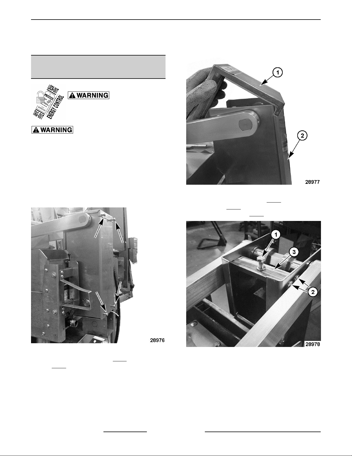
Fig. 3
4. Loosen bump stop bolt (1, Fig. 4) and remove
screws (2, Fig. 4) from each side that secures
bump stop plate (3, Fig. 4) to rear housing.
Fig. 2
3. Remove rear housing lid (1, Fig. 3) and rear cover
(2, Fig. 3).
F45571 (0316) Page 4 of 19
5. One person fully raises clamshell by the handle
Fig. 4
to remove spring force and hold in place. The
other person removes all 4 retaining clips from
the lower pivot rod at the rear housing.
Page 5
VMCS HEAVY DUTY ELECTRIC GRIDDLE TOP - REMOVAL AND REPLACEMENT OF PARTS
Fig. 5
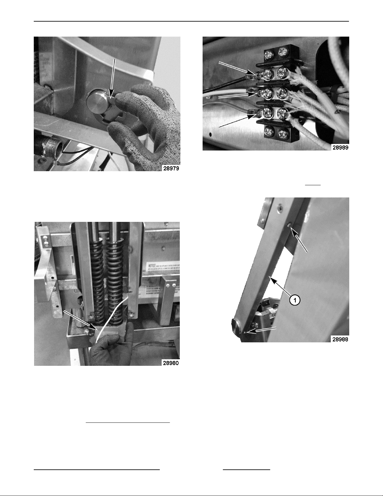
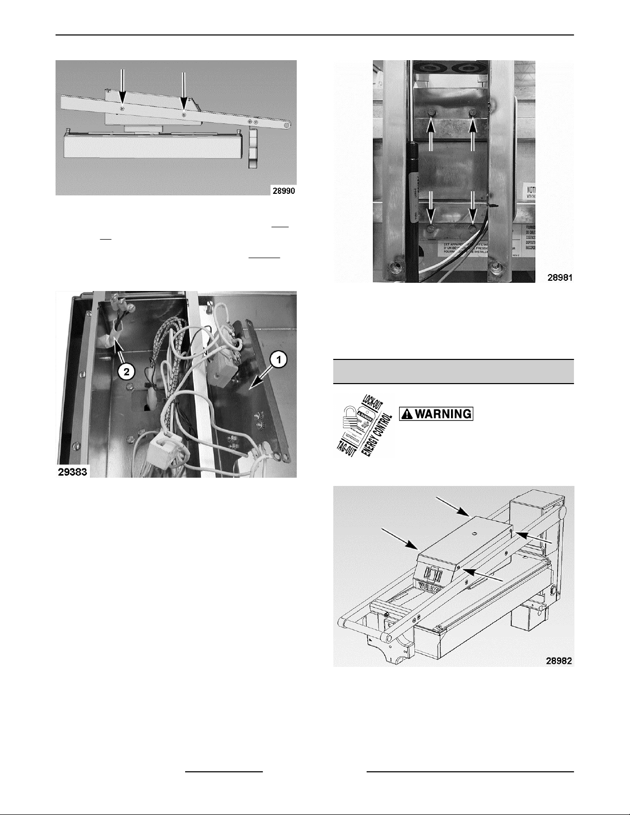
6. Push lower pivot rod out from the spring mount
(block).
Fig. 7
C. Fully raise clamshell to access the left arm
wireway cover on the bottom of arm.
Remove wireway cover (1, Fig. 8) from the
bottom of left arm.
A. Remove spring mount (block), lower spring
alignment shafts (male) and system springs.
Fig. 6
B. Lower clamshell onto griddle surface.
7. If removing top control box and clamshell from
arms to access capillary bulbs and heating
element:
Fig. 8
D. Lower clamshell and remove 4 screws on
the outer side of both arms. The screws and
locknuts secure the control box to the arms
and the control box mounting shelf inside
the box.
A. Remove TOP CONTROL BOX COVER.
B. Note locations and disconnect power supply
wires from terminal strip.
Page 5 of 19 F45571 (0316)
Page 6
VMCS HEAVY DUTY ELECTRIC GRIDDLE TOP - REMOVAL AND REPLACEMENT OF PARTS
Fig. 9
E. Lift the control box mounting shelf (1, Fig.
10) and place to the side.
F. Feed the power supply wires (2, Fig. 10)
back into the left arm enough to clear control
box.
Fig. 11
B. Remove clamshell from frame.
Fig. 10
G. Lift the arm to clear the control box then slide
control box and clamshell away from the
arms.
8. If completely removing clamshell and rear
housing from frame:
A. Remove bolts securing rear housing to
griddle frame.
9. Reverse procedure to install.
10. Check for proper operation.
TOP CONTROL BOX COVER
Disconnect the
electrical power to the machine and
follow lockout / tagout procedures.
1. Remove top control box cover.
2. Remove wiring cover plate to access electrical
F45571 (0316) Page 6 of 19
Fig. 12
components.
Page 7

VMCS HEAVY DUTY ELECTRIC GRIDDLE TOP - REMOVAL AND REPLACEMENT OF PARTS
Fig. 13
3. Reverse procedure to install.
POWER SWITCH
Fig. 15
4. Reverse procedure to install.
NOTE: Ensure that terminal connections are
completely seated and tight.
5. Check for proper operation.
INDICATOR LIGHTS
Disconnect the
electrical power to the machine and
follow lockout / tagout procedures.
1. Remove
2. Note wire locations and disconnect from switch
(1).
TOP CONTROL BOX COVER.
Disconnect the
electrical power to the machine and
follow lockout / tagout procedures.
1. Remove
2. Note wire locations and disconnect from light (1)
being replaced.
TOP CONTROL BOX COVER.
3. Pinch retaining clips and push switch (1) through
the opening.
Page 7 of 19 F45571 (0316)
Fig. 16
3. Pinch retaining clips and push light (1) through
the opening.
Page 8

VMCS HEAVY DUTY ELECTRIC GRIDDLE TOP - REMOVAL AND REPLACEMENT OF PARTS
Fig. 17
4. Reverse procedure to install.
NOTE: Ensure that terminal connections are
completely seated and tight.
5. Check for proper operation.
POWER CORD
1. Remove TOP CONTROL BOX COVER.
2. Remove rear housing lid as outlined under
REMOVE CLAMSHELL FROM FRAME.
3. Fully raise platen to access the left arm wireway
cover (1, Fig. 18) then remove the cover.
Fig. 19
5. Pull wire out from the left arm wire way, thought
grommet in top control box, through the upper
pivot rod, through rear housing wire path tube
(vertical) to remove from machine.
6. Reverse procedure to install.
7. Check for proper operation.
HIGH LIMIT
1. REMOVE CLAMSHELL FROM FRAME .
2. Note wire locations (1, Fig. 20) and disconnect
from high limit (2, Fig. 20).
3. Remove mounting nut (1, Fig. 21) securing high
Fig. 18
4. Note power cord wire locations and disconnect
from terminal strip.
F45571 (0316) Page 8 of 19
4. Access high limit capillary bulb:
Fig. 20
limit to control box mounting shelf.
A. Note wire tie locations and remove from
capillary tube and wire bundle.
B. Note heating element wire locations (2, Fig.
21) and disconnect from terminal strip.
Page 9

VMCS HEAVY DUTY ELECTRIC GRIDDLE TOP - REMOVAL AND REPLACEMENT OF PARTS
5. Reverse procedure to install.
When installing, do not bend and kink the
capillary tube or damage to the control may occur.
6. Check for proper operation.
CONTROL THERMOSTAT
Disconnect the
electrical power to the machine and
follow lockout / tagout procedures.
Fig. 21
C. Remove 12 screws (1, Fig. 22) securing
platen cover assembly (2, Fig. 22) to
clamshell assembly.
Fig. 22
D. Remove mounting clips (1, Fig. 23) securing
high limit capillary bulb to platen insulation
retainer (2, Fig. 23).
REMOVE CLAMSHELL FROM FRAME .
1.
2. Remove control thermostat knob and remove 2
screws securing thermostat to control box
mounting shelf.
Fig. 24
3. Note wire locations (1, Fig. 25) and disconnect
from control thermostat (2, Fig. 25).
Fig. 23
Fig. 25
4. Access control thermostat capillary bulb:
Page 9 of 19 F45571 (0316)
Page 10

VMCS HEAVY DUTY ELECTRIC GRIDDLE TOP - REMOVAL AND REPLACEMENT OF PARTS
A. Note wire tie locations and remove from
capillary tube and wire bundle.
B. Note heating element wire locations (1, Fig.
26) and disconnect from terminal strip.
Fig. 26
5. Remove 12 screws (1, Fig. 27) securing platen
cover assembly (2, Fig. 27) to clamshell
assembly.
Fig. 28
8. Lift platen insulation and retainer from claimshell.
9. Remove 16 mounting nuts (1, Fig. 29) securing
heating element retainer (2, Fig. 29) to platen.
Fig. 27
6. Remove 2 mounting nuts and clips (1, Fig. 28)
securing high limit capillary bulb to platen
insulation retainer (2, Fig. 28).
Do not bend and kink the capillary tube or
damage to the control may occur.
A. Position capillary bulb to the side.
7. Remove the remaining 7 mounting nuts (3, Fig.
28) from platen insulation retainer.
F45571 (0316) Page 10 of 19
10. Lift heating elements off platen to access
Fig. 29
thermostat capillary bulb.
A. Remove thermostat capillary bulb and
thermostat from clamshell assembly.
Fig. 30
Page 11

VMCS HEAVY DUTY ELECTRIC GRIDDLE TOP - REMOVAL AND REPLACEMENT OF PARTS
11. Reverse procedure to install.
12. Check for proper operation.
HEATING ELEMENTS
Disconnect the
electrical power to the machine and
follow lockout / tagout procedures.
1. REMOVE CLAMSHELL FROM FRAME .
2. Note wire tie locations and remove from capillary
tube and wire bundle.
3. Note heating element wire locations (1, Fig. 31)
and disconnect from terminal strip.
Do not bend and kink the capillary tube or
damage to the control may occur.
A. Position capillary bulb to the side.
6. Remove the remaining 7 mounting nuts (3, Fig.
33) from platen insulation retainer.
Fig. 31
4. Remove 12 screw (1, Fig. 32) securing platen
cover assembly (2, Fig. 32) to clamshell
assembly.
Fig. 33
7. Lift platen insulation and retainer from clamshell.
8. Remove 16 mounting nuts (1, Fig. 34) securing
heating element retainer (2, Fig. 34) to platen.
Fig. 34
9. Lift heating elements off the platen.
10. Reverse procedure to install.
11. Check for proper operation.
Fig. 32
5. Remove mounting clips (1, Fig. 33) securing high
limit capillary bulb to platen insulation retainer (2,
Fig. 33).
Page 11 of 19 F45571 (0316)
NOTE: When installing heating elements, torque
mounting nuts to 20 in-lb.
NOTE: When installing platen insulation, hand tighten
mounting nuts plus 1/2 turn to secure.
Page 12

VMCS HEAVY DUTY ELECTRIC GRIDDLE TOP - REMOVAL AND REPLACEMENT OF PARTS
ARM MECHANISM
Disconnect the
electrical power to the machine and
follow lockout / tagout procedures.
1. Remove springs from rear housing to release
system tension as outlined under REMOVE
CLAMSHELL FROM FRAME.
2. Remove TOP CONTROL BOX COVER.
3. If removing left arm:
A. Note locations and disconnect power supply
wires from terminal strip.
Fig. 36
C. Lower clamshell.
Fig. 35
B. Fully raise clamshell to access the left arm
wireway cover on the bottom of arm.
Remove wireway cover (1, Fig. 36) from the
bottom of left arm.
D. Feed the power supply wires back into the
arm enough to clear the control box.
Fig. 37
4. Remove 2 screws on the outer side of the arm
being replaced. The screws and locknuts secure
the control box to the arm and the control box
mounting shelf inside the box.
F45571 (0316) Page 12 of 19
Page 13

VMCS HEAVY DUTY ELECTRIC GRIDDLE TOP - REMOVAL AND REPLACEMENT OF PARTS
Fig. 38
5. Remove cap from arm being replaced (cap is
threaded).
Fig. 39
6. Pull arm straight off the upper pivot rod.
NOTE: The arm handle is a loose fit between the arms
and will fall away when either arm is removed.
7. Reverse procedure to install.
8. Check for proper operation.
Page 13 of 19 F45571 (0316)
Page 14

VMCS HEAVY DUTY ELECTRIC GRIDDLE TOP - SERVICE PROCEDURES AND ADJUSTMENTS
SERVICE PROCEDURES AND ADJUSTMENTS
Certain procedures in this section require electrical test or measurements while
power is applied to the machine. Exercise extreme caution at all times and follow Arc Flash
procedures. If test points are not easily accessible, disconnect power and follow Lockout/Tagout
procedures, attach test equipment and reapply power to test.
GRIDDLE TOP MANUAL LIFT
CHECK
Always hold handle to maintain
control of the unit until lifting mechanism holds in the
desired raised position or rests in the lowered position.
Do not allow unit to swing upward or downward under
its own power as this may result in injury or equipment
damage.
Do not force unit if it does not move up and
down in the prescribed manner. The assembly may be
damaged by the application of excessive upward or
downward force.
NOTE: A spring force adjustment is not provided on
this unit. It's designed to apply a consistent downward
force on the food product regardless of thickness. Use
the PLATE GAP ADJUSTER to prevent crushing of
soft foods by the downward force of the unit.
Perform this procedure to manually check the raising
and lowering operation of the griddle top.
1. Grasp the handle Fig. 40 and raise unit (1, Fig.
41) to its maximum height of approximately 53
angular degrees then stop.
3. Grasp the handle and lower the unit (2, Fig. 41)
until it contacts griddle cooking surface.
Fig. 41
4. If the lifting operation was smooth without binding
or catching and remained in place at the raised
position then servicing is not necessary. If the
lifting operation was binding and catching then
inspect the lifting mechanism for damaged, loose
or missing hardware and service to repair as
necessary.
The plate gap adjuster (1, Fig. 42) is used to prevent
soft foods from being crushed by the downward force
of the unit. The 1" setting would be used for the
smallest or no gap with 4" being used to create the
largest gap.
Settings are changed by rotating the gap adjuster to
the left or right until it locks in place at the desired gap
setting.
Fig. 40
2. Release the handle and verify unit remains in
place.
F45571 (0316) Page 14 of 19
PLATE GAP ADJUSTER
Page 15

VMCS HEAVY DUTY ELECTRIC GRIDDLE TOP - SERVICE PROCEDURES AND ADJUSTMENTS
B. If voltage is correct, check current draw
(amps) through the heating element lead
wires.
NOTE: This method is preferred over a resistance
check when a clamp on type amp meter is available.
2. If current draw is correct then heating element is
functioning properly.
See following table for proper values.
3. If current draw is not correct, turn griddle top OFF
and disconnect the electrical supply.
A. Replace heating element then proceed to
step 5.
4. If unable to check current draw, a resistance
check may indicate a malfunctioning element.
Fig. 42
THERMOSTAT TEST
1. Position temperature tester probe in center of
griddle top plate, 8" down from the top edge.
2. Turn griddle top on and set to 350°F. Allow
thermostat to cycle 3 times to preheat.
3. Record temperature when indicator light turns
ON and OFF. Repeat for 3 cycles.
4. Calculate the temperature differential.
Differential = Indicator Light OFF - Indicator Light
ON
Example: 365 - 340 = 25°F differential
A. Differential should be less than 50°F.
B. If differential is greater than 50°F, replace
control thermostat.
5. Calculate the average temperature.
Average Temperature =
A. Disconnect electrical supply and remove
lead wires from heating element. Check
resistance (ohms).
See following table for proper values.
5. Check for proper operation.
VOLTS POWER AMPS OHMS
208 3.6 kW 17.3 12
240 3.6 kW 15 16
1. Values in table are nominal.
Tolerance is +5/-10%.
NOTES:
2. Resistance values (ohms) are @
77°F room temperature.
Indicator Light OFF + Indicator Light ON
2
Example: 365 + 345 = 710 ÷ 2 = 355°F
6. If average temperature differs more than 50°F
from the dial setting, replace thermostat.
HEATING ELEMENT TEST
1. Measure voltage at heating element leads and
verify against data plate voltage.
A. If voltage is incorrect, find the source of the
problem.
Page 15 of 19 F45571 (0316)
Page 16

VMCS HEAVY DUTY ELECTRIC GRIDDLE TOP - ELECTRICAL OPERATION
ELECTRICAL OPERATION
COMPONENT LOCATION
ITEM NO. DESCRIPTION
1 High Limit Reset - Access Plug
2 Thermostat Cover
3 Thermostat Adjustment Knob
4 High Limit Reset Button
5 Power Switch
6 Power Light (Amber)
7 Heating Light (Amber)
COMPONENT FUNCTION
Power Switch ......... Power switch turns griddle top ON and OFF.
Indicator Light
(Power) ...............
Indicator Light
(Thermostat) ..........
Thermostat ........... Monitors temperature of griddle top and cycles power to heating element.
Left amber light indicates when power switch is turned ON.
Right amber light indicates when thermostat is calling for heat.
F45571 (0316) Page 16 of 19
Page 17

VMCS HEAVY DUTY ELECTRIC GRIDDLE TOP - ELECTRICAL OPERATION
High Limit ............ Protects griddle top by cutting power to heating element if temperature goes above 624°F.
A manual reset device (after cool down).
Heating Element ...... Heat source for griddle top.
WIRING DIAGRAM
Fig. 44
Page 17 of 19 F45571 (0316)
Page 18

VMCS HEAVY DUTY ELECTRIC GRIDDLE TOP - TROUBLESHOOTING
TROUBLESHOOTING
TROUBLESHOOTING
SYMPTOM POSSIBLE CAUSE
1. Thermostat set too low for current griddle
temperature.
2. High limit tripped - Press reset button (after cool
Heat does not come on when power switch is turned ON.
(Amber Power Light ON)
down).
3. High limit malfunction.
4. Power switch malfunction.
5. Thermostat malfunction.
6. Heating element malfunction.
1. Power switch not in the ON position.
2. High limit tripped - Press reset button (after cool
down).
Heat does not come on when thermostat is turned ON.
(Amber Heat Light OFF)
Unit will not raise or lower. 1. Check spring mechanism and look for interference.
Food under-cooked.
Food over-cooked.
Food is being crushed.
3. Power not supplied to unit.
4. Check wiring connections.
5. Power switch malfunction.
6. Thermostat malfunction.
7. Heating element malfunction.
1. Temperature set too low.
2. Food not cooked long enough. See Operation &
Field Installation Manual.
3. Cooking surface not touching or partially touching
food when in the lowered position. Turn PLATE GAP
ADJUSTER to a lower setting.
1. Temperature set too high.
2. Food cooked too long. See Operation & Field
Installation Manual.
3. Cooking surface pressing down too hard when in the
lowered position. Turn PLATE GAP ADJUSTER to
a higher setting.
1. Cooking surface pressing down too hard when in the
lowered position. Turn PLATE GAP ADJUSTER to
a higher setting.
F45571 (0316) Page 18 of 19
Page 19

VMCS HEAVY DUTY ELECTRIC GRIDDLE TOP - TROUBLESHOOTING
SYMPTOM POSSIBLE CAUSE
1. Temperature set too high or too low.
2. Cooking surface needs to be cleaned. See
Food sticks to cooking surface.
Operation & Field Installation Manual.
3. Cooking surface not covered with enough cooking
oil.
4. Cooking surface warn or damaged.
Page 19 of 19 F45571 (0316)
 Loading...