

Page 1
McDONALD'S®
INSTALLATION, SERVICE
& PARTS MANUAL FOR
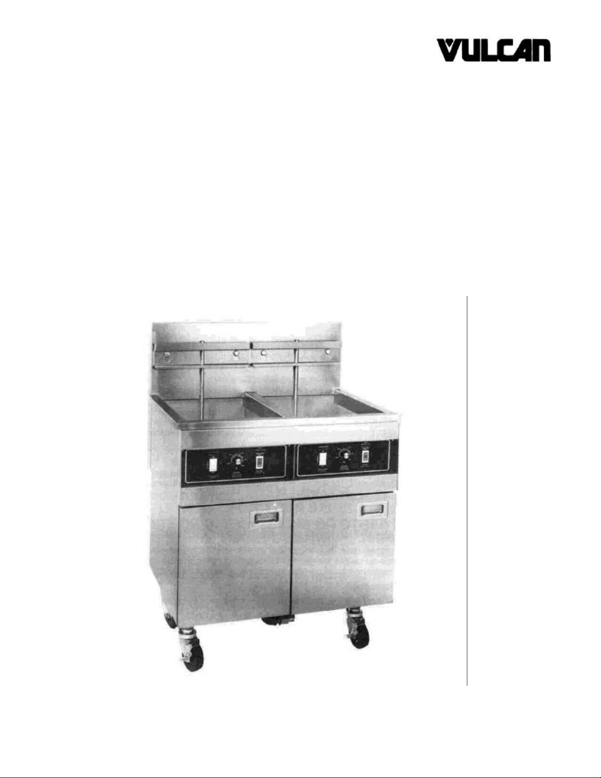
GEF-M&SM SERIES
GAS FRYERS
VULCAN-HART CORPORATION, 3600 NORTH POINT BOULEVARD, BALTIMORE, MARYLAND 21222
Page 2
OPERATING, INSTALLATION AND SERVICE PERSONNEL
Operating information for this equipment has been prepared for use by qualified and/or authorized operating
personnel.
All installation and service on this equipment is to be performed by qualified, certified, licensed and/or
authorized installation or service personnel, with the exception of any marked with a ? in front of the part
number.
Service may be obtained by contacting the Factory Service Department, Factory Representative or Local
Service Agency.
DEFINITIONS
QUALIFIED AND/OR AUTHORIZED OPERATING PERSONNEL
Qualified or authorized operating personnel are those who have carefully read the information in this manual
and are familiar with the equipment's functions or have had previous experience with the operation of the
equipment covered in this manual.
QUALIFIED INSTALLATION PERSONNEL
Qualified installation personnel are individuals, a firm, corporation or company which either in person or
through a representative are engaged in, and are responsible for:
1. The installation of gas piping from the outlet side of the gas meter, or the service regulator when the meter
is not provided, and the connection and installation of the gas appliance. Qualified installation personnel
must be experienced in such work, be familiar with all precautions required, and have complied with all
requirements of state or local authorities having jurisdiction. Reference in the United States of America National Fuel Gas code ANSI Z223.1 (Latest Edition). In Canada-Canadian Standard CAN1-B149.1 NAT.
GAS (Latest Edition) or CAN1-B149.2 PROPANE (Latest Edition).
2. The installation of electrical wiring from the electric meter, main control box or service outlet to the electric
appliance. Qualified installation personnel must be experienced in such work, be familiar with all
precautions required, and have complied with all requirements of state or local authorities having
jurisdiction. Reference: In the United States of America-National Electrical Code ANSI NFPA No. 70
(Latest Edition). In Canada-Canadian Electrical Code Part 1 CSA-C22.1 (Latest Edition).
QUALIFIED SERVICE PERSONNEL
Qualified service personnel are those who are familiar with Vulcan equipment who have been endorsed by
the Vulcan-Hart Corporation. All authorized service personnel are required to be equipped with a complete set
of service parts manuals and stock a minimum amount of parts for Vulcan equipment.
SHIPPING DAMAGE CLAIM PROCEDURE
For your protection, please note that equipment in this shipment was carefully inspected and packed by
skilled personnel before leaving the factory. The transportation company assumes full responsibility for safe
delivery upon acceptance of this shipment.
If shipment arrives damaged:
1. VISIBLE LOSS OR DAMAGE — Be certain this is noted on freight bill or express receipt and signed by
person making delivery.
2. FILE CLAIM FOR DAMAGES IMMEDIATELY — Regardless of extent of damage.
3. CONCEALED LOSS OR DAMAGE — If damage is unnoticed until merchandise is unpacked, notify
transportation company or carrier immediately, and file "concealed damage" claim with them. This should
be done within (15) days of date of delivery is made to you. Be sure to retain container for inspection.
We cannot assume responsibility for damage or loss incurred in transit. We will, however, be glad to furnish
you with necessary documents to support your claim.
PLEASE RETAIN THIS MANUAL FOR FUTURE REFERENCE
Page 3

IMPORTANT NOTES FOR ALL VULCAN APPLIANCES
1. These units are produced with the best possible workmanship and material. Proper installation is vital if best performance and
appearance are to be achieved. Installer must follow the installation instructions carefully.
2. Information on the construction and installation of ventilating hoods may be obtained from the "Standard for the installation of
equipment for the removal of smoke and grease laden vapors from commercial cooking equipment," NFPA No. 96 (latest
edition) available from the National Fire Protection Association, Battery March Park, Quincy MA 02269.
3. For an appliance equipped with a flexible electric supply cord, the cord is equipped with a three prong (grounding) plug. This
grounding plug is for your protection against shock hazard and should be plugged directly into a properly grounded three prong
receptacle. Do not cut or remove the grounding prong from this plug. If the appliance is not equipped with a grounding plug, and
electric supply is needed, ground the appliance by using the ground lug provided (refer to the wiring diagram).
(FOR GAS APPLIANCES ONLY)
4. Do not obstruct the air flow into and around the appliance. This air flow is necessary for proper combustion of gases and for
ventilation of the appliance. Provisions for ventilation of incoming air supply for the equipment in the room must be in accordance
with National Fuel Gas Code ANSI Z223.1 (latest edition).
5. Do not obstruct the flow of flue gases from the flue duct (when so equipped) located on the rear (or sides) of the appliance. It is
recommended that the flue gases be ventilated to the outside of the building through a ventilation system installed by qualified
personnel.
6. For an appliance equipped with casters, (1) the installation shall be made with a connector that complies with the Standard for
Connectors for Movable Gas Appliances, ANSI Z21.69 (latest edition), and Addenda, Z21.69a (latest edition), and a quickdisconnect device that complies with the Standard for Quick-Disconnect Devices for Use With Gas Fuel, ANSI Z21.41 (latest
edition), and Addenda, Z21.41a (latest edition) and Z21.41b (latest edition), and (2) adequate means must be provided to limit
the movement of the appliance without depending on the connector and the quick-disconnect device or its associated piping to
limit the appliance movement. If disconnection of the restraint is necessary, reconnect this restraint after the appliance has been
returned to its originally installed position.
7. The appliance and its individual shutoff valve must be disconnected from the gas supply piping system during any pressure
testing of that system at test pressures in excess of 1/2 psig (3.45 k Pa).
8. The appliance must be isolated from the gas supply system by closing its individual manual shutoff valve during any pressure
testing of the gas supply system at test pressures equal to or less than 1/2 psig (3.45 k Pa).
CAUTIONS
FOR YOUR SAFETY
DO NOT STORE OR USE GASOLINE OR OTHER FLAMMABLE VAPORS AND LIQUIDS
IN THE VICINITY OF THIS EQUIPMENT OR ANY OTHER APPLIANCE.
1. KEEP THE APPLIANCE FREE AND CLEAR FROM ALL COMBUSTIBLE SUBSTANCES.
2. IN THE EVENT A GAS ODOR IS DETECTED, SHUT UNIT(S) DOWN AT THE MAIN
SHUTOFF VALVE AND CONTACT THE LOCAL GAS COMPANY OR GAS SUPPLIER
FOR SERVICE.
3. POST IN A PROMINENT LOCATION, INSTRUCTIONS TO BE FOLLOWED IN THE EVENT
THE SMELL OF GAS IS DETECTED. THIS INFORMATION MAY BE OBTAINED FROM A
LOCAL GAS SUPPLIER.
Page 4

GEF INSTALLATION, SERVICE & PARTS MANUAL INDEX
DESCRIPTION PAGE
DEFINITIONS (Inside Front Cover)
CAUTIONS
IMPORTANT NOTES 1
INDEX 2
SECTION I INSTALLATION
UNCRATING INSTRUCTIONS 3
ELECTRIC CONNECTIONS 3
GAS SUPPLY CONNECTIONS 4
POSITIONING FRYER UNDER HOOD 4
SECTION II SERVICING
CONTROLS 5
AIR ADJUSTMENT 6
HIGH LIMIT TEST & PROCEDURES 6
CLEANING BLOWER INLET SCREEN & WHEEL 6
CALIBRATION PROCEDURES 7
TROUBLE SHOOTING 8-9
SECTION III PARTS
PARTS LIST 10-24
REVISION SHEET (Inside Back Cover)
NOTES
A Rating Plate is located on the inside fryer door panel stating the Model Number, Serial Number,
Type of Gas, Voltage and Amperage.
A complete set of Wiring Diagrams are included in the back of this manual. A Wiring Decal may
also be found on the inside lower front panel.
GEF-SM units all require an isolation relay to isolate each tank vat section of the fryer. The
isolation relay is located behind the front control panel.
This appliance is to be installed with a six inch clearance at the sides and rear to combustible
construction.
Fryer must be installed at least 16 in. away from open top flame units.
Motors in GEF fryers are permanently lubricated and require no additional maintenance.
The vent of this appliance should be checked every 6 months for restrictions.
2
Page 5
GEF UNCRATING
INSTRUCTIONS
ELECTRIC CONNECTION
The following procedure should be followed when
uncrating all GEF Fryers.
1. Pry right and left hand crate sides off of crate back
and front.
2. Pry crate back and front off of crate bottom.
3. Remove cardboard box containing component parts
from the 2x4 wood packaging braces.
4. Using caution, cut (2) straps and remove (2) 2 x 4
wood braces.
5. Remove protective plastic liner from unit.
6. Remove packaging material from unit.
7. Assemble legs and remove unit from crate bottom
as near to final resting place as possible.
8. Open cardboard box containing component parts
and unwrap parts. Care should be taken when
checking unit quantities. See chart below for correct
contents of parts.
UNIT
PART DESCRIPTION
Basket Hanger 1 2 3 1 2 3
Quick Disconnect 1 1 1 1 1 1
Rack Supports 2 4 6 2 4 6
Probe Tubes 1 2 3 2 4 6
Clean Out Rod 1 1 1 1 1 1
1M 2M 3M 2SM 4SM 6SM
QUANTITIES
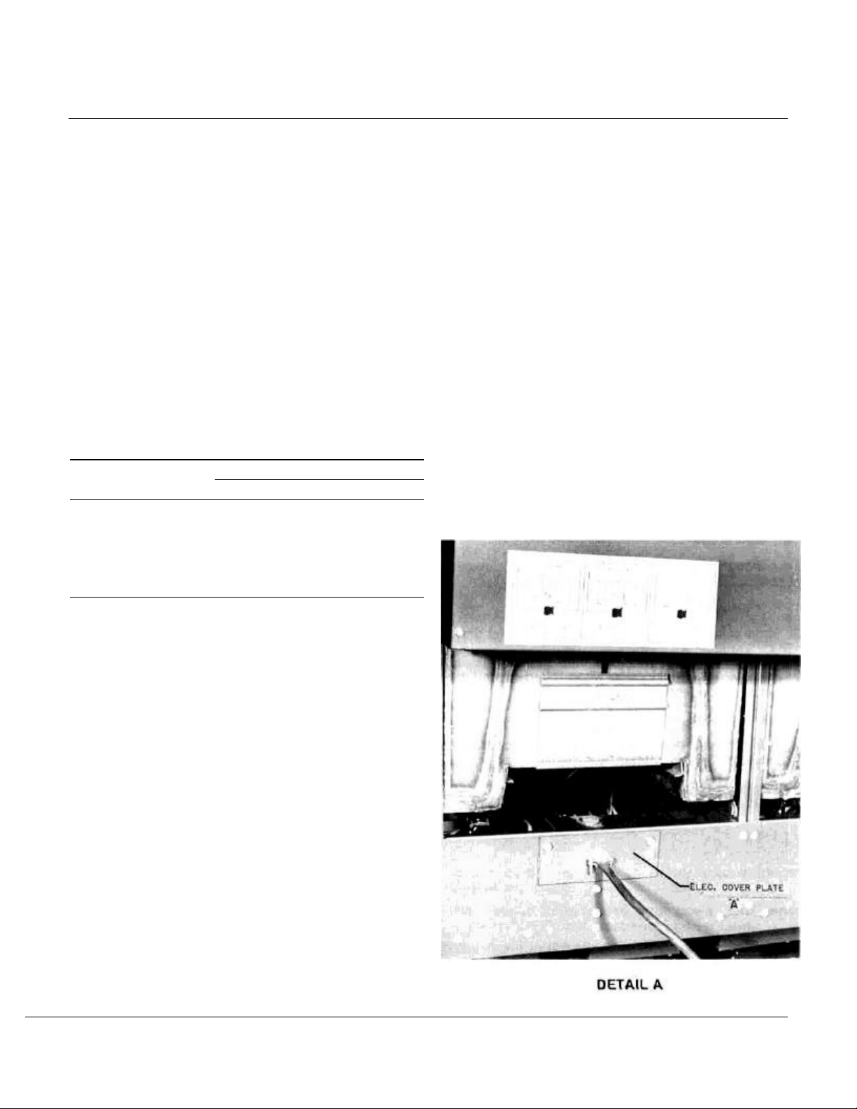
Position fryer as near to final resting place as possible.
Connect 120V AC electric supply to fryer barrier strip.
Barrier strip may be connected from rear of unit. To
reach barrier, remove electric cover plate "A" from unit.
After connecting 120V AC electric supply to fryer
barrier strip, verify with a voltmeter that the following
condition exists. See Detail "A".
1. Black to White 120V AC.
2. Black to Ground 120V AC.
3. White to Ground 0.00V AC.
Make all other necessary electrical connections.
Improper grounding and/or polarity will result in lock
out of unit and eventual damage to the ignition
systems.
This unit is supplied with a 6 1/2 foot long 3 wire supply
cord. This appliance is equipped with a 3 prong
(grounding) plug for your protection against shock
hazard and should be plugged directly into a properly
grounded three prong receptacle. DO NOT cut or
remove the grounding prong from this plug.
3
Page 6
POSITIONING FRYER
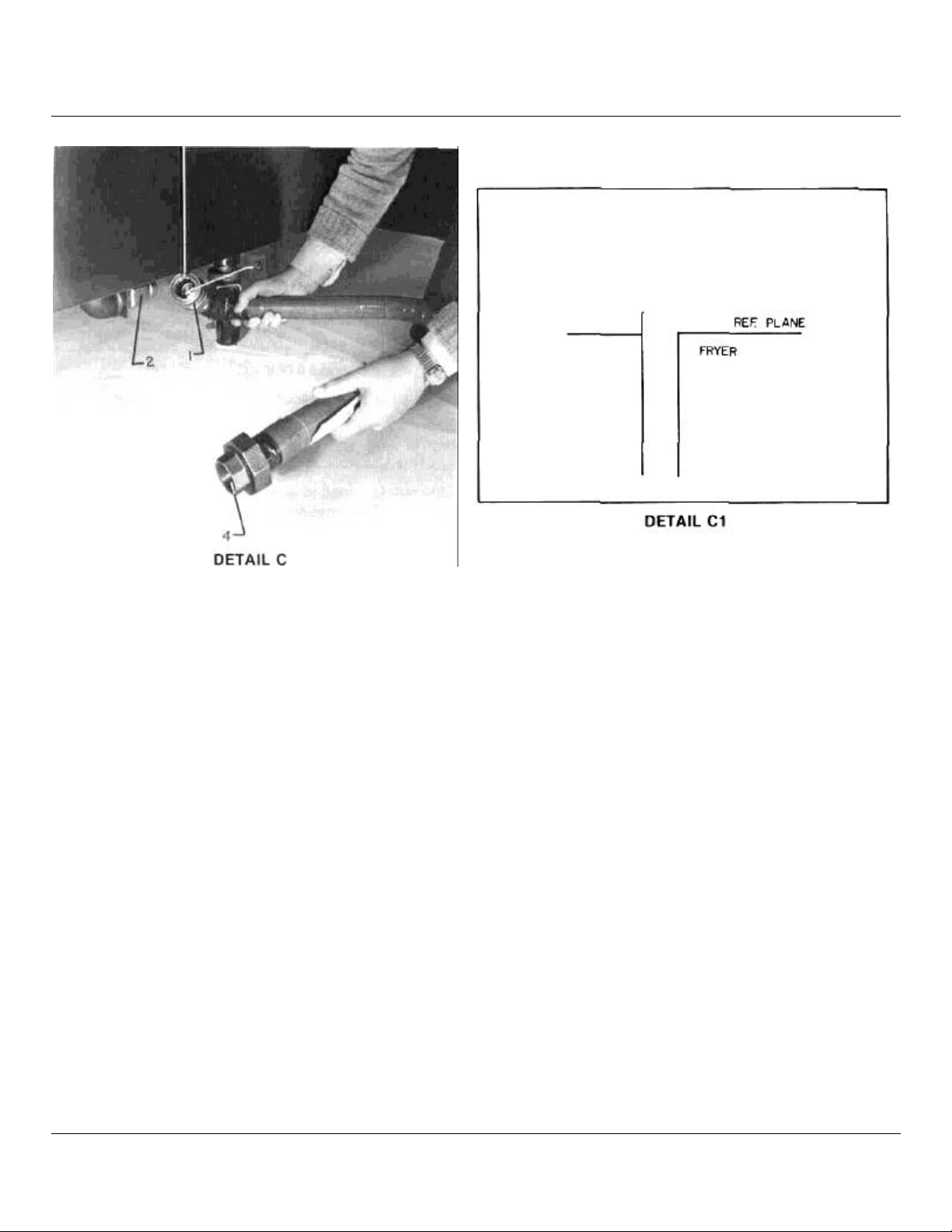
GAS SUPPLY CONNECTION UNDER HOOD
SIDE ARM
See Detail "C"
All GEF Fryers are equipped with a 3.7"W.C. 3/4" reg-
ulator for natural gas and a 10" W.C. 3/4" regulator for
propane gas.
To connect unit to gas supply, attack quick disconnect
supplied with unit to male fitting as follows:
1. Pull disconnect collar #1 back.
2. Snap disconnect #2 on to male disconnect fitting "C"
supplied on unit.
3. Release disconnect collar when fitting #3 and disconnect #2 snap into place.
4. Connect union #4 to gas supply.
5. Turn main gas supply on and test for gas leakage at all
connecting points.
Fryer is supplied with four adjustable height legs. Legs
should be adjusted so that the fryer is level and at its
proper height in the hood. See Detail — C1.
Position fryer so that it may be pushed straight back
under the hood. Place main top onto fryer by tilting main
top while pushing fryer under hood. After the main top
has cleared the hood, position main top so that it rests
evenly on the unit.
4
Page 7
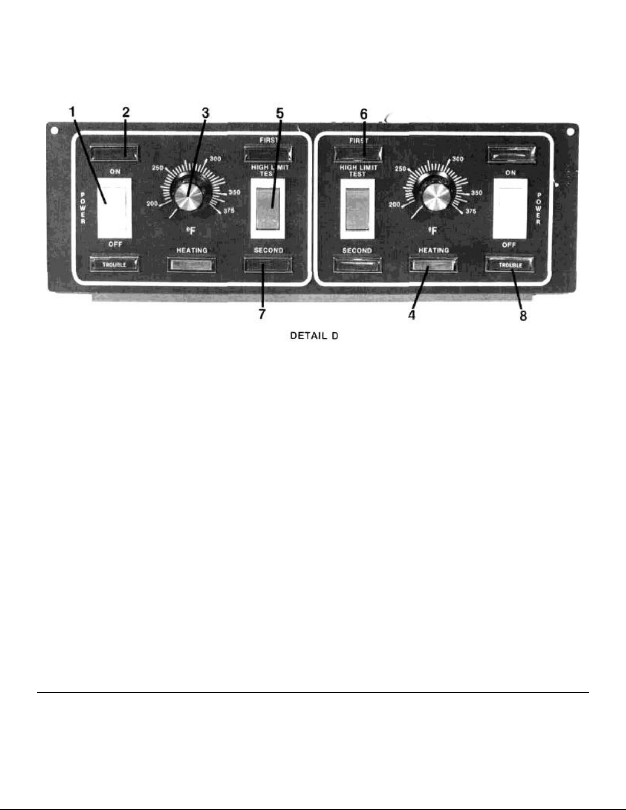
CONTROLS
SWITCH PANEL CONTROLS
(Refer to Detail "D")
1. MASTER SWITCH — Controls electric supply to unit
2. POWER "ON" LIGHT — Light indicates when electrical supply is on.
3. TEMPERATURE CONTROL — Maintain frying temperature by controlling power supply.
4. HEATING LIGHT — When "ON" indicates temperature control is calling for gas to burners.
5. HIGH LIMIT TEST SWITCH — Bypasses temperature control for testing of high limit thermostats.
6. FIRST HIGH LIMIT LIGHT — When "ON" indicates first high limit thermostat has shut down unit.
7. SECOND HIGH LIMIT LIGHT — When "ON" indicates second high limit thermostat has shut down unit. (Reset required*)
8. TROUBLE LIGHT — Indicates solid state ignition device has "locked out". (Reset required*)
9. IGNITOR RESET BUTTON
*NOTE: To reset, turn main power switch off, then on.
— See Detail "D" — When up indicates excessive heat or current in control board, allow to cool push
down to reset. If tripping continues, contact service agency.
OPERATIONAL LIGHTING INSTRUCTIONS:
To turn on, push power switch to "ON" position; turn
thermostat dial to temperature desired.
To turn off, push power switch to "OFF" position.
NOTE: Service valve must be in "ON" position and
power cord connected to power source for unit operation.
For service or extended shut down, turn service valve to
"OFF" and disconnect power cord.
The above information may also be found on the inside of
fryer door panel.
5
Page 8
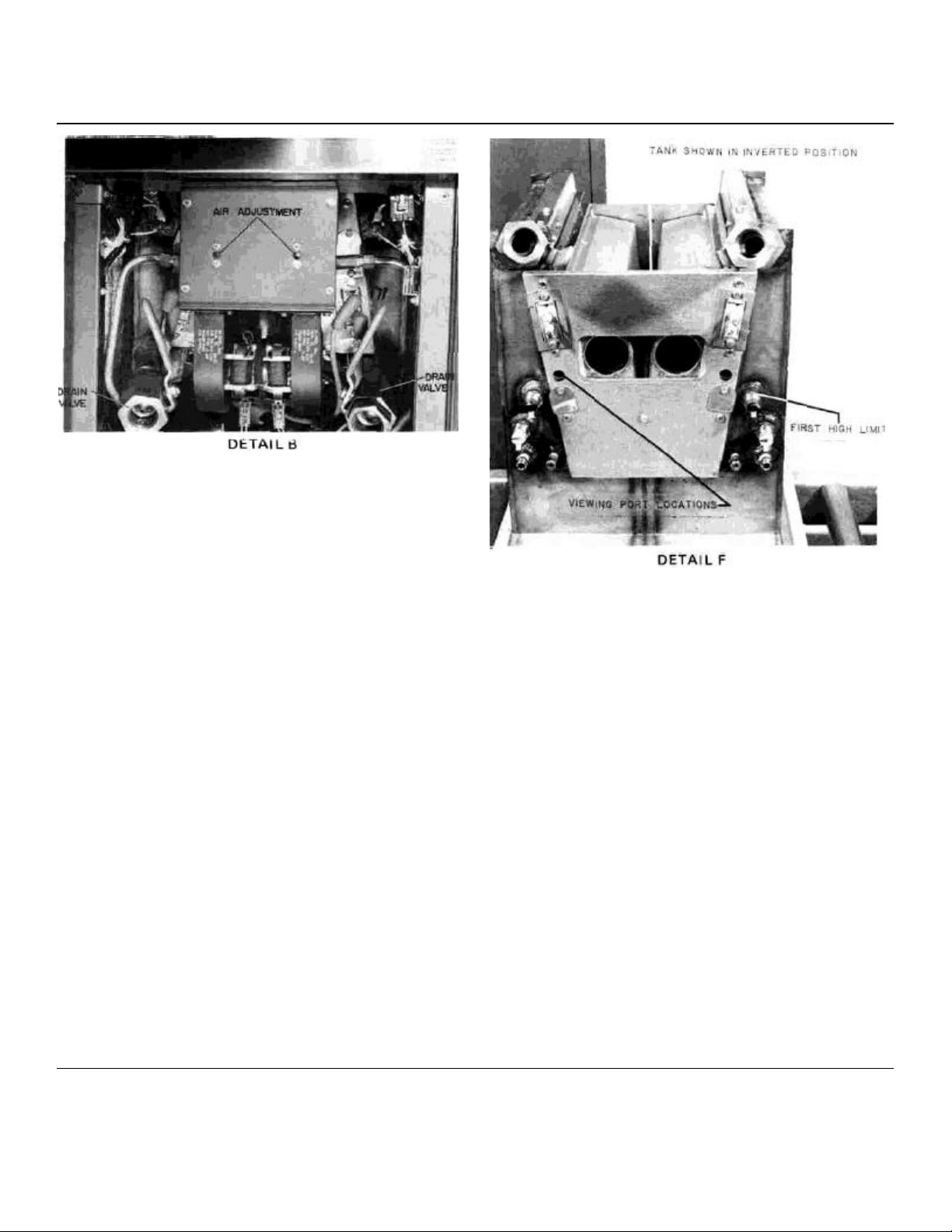
AIR ADJUSTMENT
HIGH LIMIT TEST
A blue flame seen out of the viewing port indicates
insufficient air. To correct this condition, remove plug
button from air adjustment plunger opening. Using a 1/8"
allen wrench, remove two set screws 1/4-28 NF X 3/8"
Long (one from each opening).
Replace allen wrench back into each opening and rotate
wrench counterclockwise to reduce flame in viewing port
and clockwise to increase flame. The air adjustment has
been properly made when flame is not seen out of the
viewing port and a maximum red glow is achieved on the
burners. (See Detail "B")
CLEANING BLOWER INLET
SCREEN AND WHEEL
For preventative maintenance and maximum performance
of the blower motor, the inlet screen and blower wheel
should be cleaned once a month as follows:
1. Turn power switch "OFF".
2. Remove two (2) wing nuts from side of blower motor.
3. Remove blower inlet screen.
4. Remove blower wheel.
5. Soak blower inlet screen and wheel in mild soap and
water solution. Dry thoroughly before replacing parts.
6. Reassemble screen and wheel to unit, and tighten wing
nuts.
7. Turn power switch to "ON" position and resume unit
operation.
PROCEDURE
A test to determine if the protection devices are properly
functioning. (See steps 1 thru 5)
1. Turn master switch on and set temperature knob to frying
temperature.
2. Heat shortening until heating light goes off.
3. Depress top of high limit test switch and hold until first high
limit comes on, then release switch. (Light will come on at
390 degrees F.-420 degrees F.)
4. Depress bottom of high limit test switch and hold until
second high limit light comes on, then release switch. (Light
will come on at 420 degrees F.-445 degrees F.)
5. Once unit cools down, reset by turning main power switch off
and then on, normal frying operation will then automatically
be resumed.
The above instructions may also be found on the inside fryer
door.
(Refer to Detail "F" for high limit location and viewing ports
location).
6
Page 9

CALIBRATION PROCEDURES
1. Place shortening pyrometer and pyrometer holding fixtures
or shortening digital and digital holding fixture in kettle
exactly where probe is located.
2. Turn power switch on and coming up from lower
temperature, set temperature control knob to frying
temperature.
3. Agitate shortening and allow unit to reach desired cooking
temperature (when heating light goes on), and maintain it for
15 minutes.
4. Check reading on pyrometer or digital thermometer. It should
be within 5 degrees of temperature control setting. If reading
is not within 5 degrees
of temperature control setting when the heating light turns
on, the following steps should be taken:
A. Loosen set screw in temperature control knob.
B. Rotate knob and set to read the same as pyrometer or
digital thermometer reading when the heating light turns
on.
C. Tighten set screw.
D. Allow unit to cycle and check readings.
E. Should for any reason calibration not be obtained in this
manner, call a service agency.
7
Page 10

TROUBLE SHOOTING
PROBLEM
(SPLIT VAT MODEL)
RIGHT SIDE HEATING NORMALLY.
LEFT SIDE LOCKS
OUT AFTER 3 SECONDS.
BLOWER DOES NOT RUN
WHEN LEFT SIDE CALLS
FOR HEAT.
POWER SWITCH ON, POWER
LIGHT ON, HEATING LIGHT
COMES ON, THEN TROUBLE
LIGHT COMES ON, HEATING
LIGHT GOES OUT.
CAUSE
A.
Defective blower relay. A. Call service agency.
A.
Ignition system did not sense A. Reset - Turn power switch off
flame.
1. Burner observation ports
left open.
2. Insufficient gas, check
pressure.
3. Improper ventilation.
4. Improper air adjustment.
5. Improper ignitor positioning.
6. Defective ignitor or wires.
7. Fryer gas shut off valve
closed.
8. Gas hose not connected
tightly to fryer.
REMEDY
then on.
1. Close observation ports &
tighten securing bolts.
2. Call service agency.
3. Adjust ventilator system
for proper fluing.
4. Adjust air shutter, see
instructions.
5. Call Service Agency.
6. Call Service Agency.
7. Open shut off valve.
8. Check and insure quick disconnect
fitting snaps on to fitting completely.
9. Loose connections at
ignitors.
A.
POWER SWITCH ON. POWER
LIGHT ON. 1ST HIGH LIMIT
LIGHT ON. 2ND HIGH LIMIT
ON. TROUBLE LIGHT ON.
NO HEAT.
FRYER DOES NOT GO INTO
FAT MELT (FULL HEAT
WHEN TURNED ON)
OUT OF FAT MELT FUNCTION.
SLOW RECOVERY. A. Improper ventilation. A. Adjust ventilator system
Oil temperature above 435 A. Allow fryer to cool to below 375
degrees F.
1. Temperature control out of
calibration.
2. Temperature control defective
A.
Defective fat melt timer. A. Call Service Agency.
B.
Defective fat melt thermostat. B. Call Service Agency.
A.
Defective fat melt thermostat. A. Call Service Agency. FRYER DOES NOT COME
B.
Loose wire. B. Call Service Agency.
B.
Gas pressure low. B. Call Service Agency.
9. Turn fryer off and insure push
on connectors are on tight.
degrees F. Turn off main power
switch, then on.
1. Recalibrate. Follow calibration
instructions enclosed.
2. Call Service Agency.
for proper fluing.
8
Page 11

TROUBLE SHOOTING
PROBLEM
TROUBLE LIGHT FLASHES
MOMENTARILY THEN HEATING
LIGHT COMES ON WHEN SYSTEM
CALLS FOR HEAT.
POWER SWITCH ON POWER ON
LIGHT OFF. NO HEATING.
ON,
NO HEAT.
POWER SWITCH ON,
POWER LIGHT ON,
VENTILATOR OFF.
NOISY IGNITION.
1ST HIGH LIMIT LIGHT OR 2ND
HIGH LIMIT LIGHT DOES NOT COME
ON WHEN HIGH LIMIT TEST IS
PERFORMED, OIL TEMPERATURE
IS ABOVE 475 DEGREES F.
INDICATOR LIGHT "POWER ON
HEATING-1ST HIGH LIMIT
TROUBLE" DOES NOT COME ON
WHEN IT SHOULD.
CAUSE
This is normal operation
REMEDY
A.
No power to fryer. A.
B.
Defective On Switch. B. Call Service Agency.
C.
Loose wire. C. Call Service Agency.
A. Temperature controller set below frying
temperature.
B.
Defective fat melt timer. B. Call Service Agency.
C.
Defective temperature control system. C. Call Service Agency.
A.
Loose wire in interlock system. A. Call Service Agency.
B.
Defective power on switch (1/2) B. Call Service Agency.
C.
Ventilator circuit breaker off. C. Reset ventilator circuit breaker.
D.
Defective ventilator motor. D. Call Service Agency.
A.
Improper air. A. Adjust ventilator system for proper fluing.
B.
Ignitor in upside down. B. Call Service Agency.
C.
Ignitor location incorrect. C. Call Service Agency.
High limit defective.
1. Check power supply cord verify
plugged in.
2. Check store circuit breaker.
A.
Set knob to frying temperature. POWER SWITCH ON, POWER LIGHT
Shutdown fryer and tag it for non-use
until service is obtained.
Light defective.
Call Service Agency to replace light.
9
Page 12

GEF FRYER REPLACEMENT PARTS LIST & PHOTOGRAPHS
The following information must accompany a replacement parts order or it cannot be filled.
A. Model and style or serial number.
B. Type of gas, voltage and amperage.
C. Appliance finish, permafinish, stainless steel, etc. (if applicable to parts to be replaced).
This information can be found on the rating plate of the unit. Parts may be ordered from your dealer, service agency or the factory.
Orders to the factory should be addressed as shown below. Be sure to note on order form McDonald's parts.
VULCAN-HART CORPORATION, 3600 NORTH POINT BLVD., BALTIMORE, MD 21222
10
Page 13

PARTS LIST
11
ITEM
NO. DESCRIPTION NO. -1M -2M -3M 2SM 4SM 6SM
1 MYLAR CONTROL PANEL COVER (SINGLE 375 DEG.) 114194-2 1 2 3
1A MYLAR CONTROL PANEL COVER (SINGLE 400 DEG.) 114194-1 1 2 3
2 MYLAR CONTROL PANEL COVER (SPLIT 375 DEG.) 114043-2
2A MYLAR CONTROL PANEL COVER (SPLIT 400 DEG.) 114043-1
3 DOOR ASSEMBLY 114122-G2 1 2 3 1 2 3
4 DOOR HANDLE 114211-1 1 2 3 1 2 3
5 TANK ASSEMBLY (SINGLE) 113903-G2 1 2 3
6 TANK ASSEMBLY (SPLIT) 114090-G2
10 ELEC. SUPPLY CORD 115V (NS) 105016-1 1 1 1 1 1 1
11 ELEC. BOX COVER WITH HOLE 114219-2 1 2 3 1 2 3
12 PLUG BUTTON (N.S.) 3.0317-8 2 3 4 2 3 4
13A MAIN TOP ASSEMBLY (DOUBLE UNIT) (N.S.) 114325-G2
13 MAIN TOP ASSEMBLY (SINGLE UNIT) (N.S.) 114325-G1 1
13B MAIN TOP ASSEMBLY (TRIPLE UNIT) 114325-G3
14 HANGER BUTTON 111686-2
15 BASKET HANGER 114206-1 1 2 3 1 2 3
16 PROBE TUBE 114159-1 1 2 3 2 4 6
N.S. =NOT SHOWN BY PHOTOGRAPH
PART GEF GEF GEF GEF GEF GEF
1 2 3
1 2 3
1 2 3
1
1
1
4 6
1
4 6
1
Page 14

PARTS LIST
ITEM
NO. DESCRIPTION NO. -1M -2M -3M 2SM 4SM 6SM
2 MYLAR CONTROL PANEL (SPLIT 375 DEG.) 114043-2
2A MYLAR CONTROL PANEL (SPLIT 400 DEG.)
17 POTENTIOMETER KNOB 114254-1
25 CONTROL PANEL ASSEMBLY 114042-G2
19 SIGNAL LIGHT (RED) 111496-E4
20 ON-OFF SWITCH 111496-B1
21 TROUBLE LIGHT 111496-E6
22 HEAT LIGHT (AMBER) 111496-E3
23 TEST SWITCH 111496-B3
24 POTENTIOMETER 114147-1
12
PART GEF GEF GEF GEF GEF GEF
1 2 3
1 2 3
2 4 6
1 2 3
6 9 12
2 4 6
2 4 6
2 4 6
2 4 6
2 4 6
Page 15

PARTS LIST
ITEM
NO.
DESCRIPTION NO. -1M -2M -3M 2SM 4SM 6SM
1 MYLAR CONTROL PANEL (SINGLE 375 DEG.) 114194-2 1 2 3
1A
MYLAR CONTROL PANEL (SINGLE 400 DEG.) 114194-1 1 2 3
17
POTENTIOMETER KNOB 114254-1 1 2 3
18
CONTROL PANEL ASSEMBLY (SINGLE) 114042-G1 1 2 3
19
SIGNAL LIGHT (RED) 111496-E4 3 6 9
20
ON-OFF SWITCH 111496-B1 1 2 3
21
TROUBLE LIGHT 111496-E6 1 2 3
22
HEAT LIGHT (AMBER) 111496-E3 1 2 3
23
TEST SWITCH 111496-B3 1 2 3
24
POTENTIOMETER 114147-1 1 2 3
13
PART GEF GEF GEF GEF GEF GEF
Page 16

PARTS LIST
ITEM
NO. DESCRIPTION NO. -1M -2M -3M 2SM 4SM 6SM
5 TANK ASSEMBLY (SINGLE) 113903-G2 1 2 3
16 PROBE TUBE (N.S.) 114159-1 1 2 3
26 SECOND HI LIMIT (N.S.) 114145-1 1 2 3
27 FAT MELT CONTROL (N.S.) 114143-1 1 2 3
28 FIRST HI LIMIT (N.S.) 114143-2 1 2 3
13 MAIN TOP ASSEMBLY (N.S.) 114325-G1 1
13A MAIN TOP ASSEMBLY (N.S.) 114325-G2
13B MAIN TOP ASSEMBLY 114325-G3
N.S. = NOT SHOWN BY PHOTOGRAPH
14
PART GEF GEF GEF GEF GEF GEF
1
1
Page 17

PARTS LIST
ITEM
NO. DESCRIPTION NO. -1M -2M -3M 2SM 4SM 6SM
6 TANK ASSEMBLY (SPLIT) 114090-G2
25 PROBE 3" (N.S.) 114141-1
26 SECOND HI LIMIT 114145-1
27 FAT MELT CONTROL (N.S.) 114143-1
28 FIRST HI LIMIT (N.S.) 114143-2
13 MAIN TOP ASSEMBLY (N.S.) 114325-G1
13A MAIN TOP ASSEMBLY (N.S.) 114325-G2
13B MAIN TOP ASSEMBLY (N.S.) 114325-G3
N.S. = NOT SHOWN BY PHOTOGRAPH
PART GEF GEF GEF GEF GEF GEF
15
1 2 3
2 4 6
2 4 6
2 4 6
2 4 6
1
1
1
Page 18

PARTS LIST
ITEM
NO. DESCRIPTION NO. •1M •2M -3M -2SM -4SM -6SM
7 ORIFICE SPUD (NATURAL) (NS) 109290-31 2 4 6
7A ORIFICE SPUD (LP.) (NS) 109290-49 2 4 6
28 FIRST HIGH LIMIT 114143-2 2 4 6
32 DOOR MAGNET 108834-1 1 2 3
33 DOOR HINGE (BOTTOM) 112780-5 1 2 3
34 DOOR HINGE (TOP) 112780-6 1 2 3
35 BALL VALVE 1" LEFT 114212-1 1 2 3
36 BALL VALVE 1" RIGHT 114212-2 1 2 3
38 BLOWER BOX 114692-1 1 2 3
39 BLOWER BOX COVER 114691-1 1 2 3
37 COMPONENT BOX 114158-1 1 2 3
41 B DUAL BLOWER, LEFT HAND 114160-3 1 2 3
41 C DUAL BLOWER, RIGHT HAND 114160-4 1 2 3
56 SOLENOID 111497-F1 4 8 12
52 IGNITOR 114149-1 2 4 6
48 CONDUIT (NS) 114540-915 — 1 2
51 90° COMP. FITTING 3/8 NPT X 7/16CC (NS) 114800-4 2 4 6
53 115V SUPPLY CORD (NS) 105016-1 1 1 1
49C RIGHT BURNER TUBING 1/2" 114733-1 1 2 3
49D LEFT BURNER TUBING 1/2" 1 14733-2 1 2 3
62 300 TOMIC CONNECTOR (NS) 106774-6 1 2 3
63 90° FITTING (NS) 106774-7 1 2 3
87 PLUG BUTTON (NS) 114781-1 4 8 12
59 ELBOW 1" (NS) 114798-6 2 2 2
60 NIPPLE 1" X 2-3/8" LONG (NS) 113500-F19 1 1 1
61 FRONT MANIFOLD BRACKET 114112-1 1 1 1
NS = NOT SHOWN ON PHOTOGRAPH
16
PART GEF GEF GEF GEF GEF GEF
Page 19

PARTS LIST
ITEM
NO. DESCRIPTION NO. •1M -2M -3M -2SM •4SM •6SM
7 ORIFICE SPUD (NATURAL) (NS) 109290-31 2 4 6
7A ORIFICE SPUD (L.P.)(NS) 109290-49 2 4 6
28 FIRST HIGH LIMIT 114143-2 2 2 6
32 DOOR MAGNET 108834-1 1 2 3
33 DOOR HINGE (BOTTOM) (NS) 112780-5 1 2 3
34 DOOR HINGE (TOP) (NS) 112780-6 1 2 3
35 BALL VALVE 1" LEFT 114212-1 1 2 3
36 BALL VALVE 1" RIGHT 114212-2 1 2 3
37 COMPONENT BOX COVER 114691-1 1 2 3
38 BLOWER BOX 114692-1 1 2 3
39 BLOWER BOX COVER 114691-1 1 2 3
41 B DUAL BLOWER, LEFT HAND 114160-3 1 2 3
41C DUAL BLOWER, RIGHT HAND 114160-4 1 2 3
42 1/2" SOLENOID 111497-F6 2 4 6
43 3/4" TEE 114696-5 1 2 3
44 MALE 3/8" NPT TO 1/2" CC 109700-1 2 4 6
52 IGNITOR 114149-1 2 4 6
53 115V CORD(NS) 105016-1 1 1 1
55 REGULATOR(NATURAL) (NS) 108279-5 1 1 1
55A REGULATOR (L.P.) (NS) 108279-3 1 1 1
49 B BURNER TUBING 114736-1 2 4 6
87 PLUG BUTTON 114781-1 4 8 12
PART GEF GEF GEF GEF GEF GEF
NS = NOT SHOWN ON PHOTOGRAPH
17
Page 20

PARTS LIST
ITEM
NO. DESCRIPTION NO. -1M -2M -3M -2SM -4SM -6SM
39 BLOWER BOX COVER 114691-1 1 2 3 1 2 3
83 AIR ADJUSTOR PLUNGER 114703-1 2 4 6 2 4 6
84 ADJUSTMENT SLEEVE 114706-1 2 4 6 2 4 6
85 1/8" ALLEN SET SCREW 1/4-28 NF X 1-1/4" LG. 114737-1 2 4 6 2 4 6
86 1/8" ALLEN SET SCREW 1/4-28NF X 3/8" LG. (NS) 114737-2 2 4 6 2 4 6
NS = NOT SHOWN IN PHOTOGRAPH
18
PART GEF GEF GEF GEF GEF GEF
Page 21

PARTS LIST
ITEM
NO. DESCRIPTION NO. -1M -2M -3M 2SM 4SM 6SM
3 DOOR ASSEMBLY 114122-G2 1 2 3 1 2 3
64 RATING PLATE 111955-2 1 1 1 1 1 1
65 CLEARANCE PLATE 110694-1 1 1 1 1 1 1
66 IMPORTANT PLATE 113831-1 1 1 1 1 1 1
67 INSTALLATION DECAL (N.S.) 113681-1 1 1 1 1 1 1
68 DRAIN PIPE HOOK (BOTTOM) 114245-1 1 1 1 1 1 1
69 DRAIN PIPE HOOK (TOP) 114246-1 1 1 1 1 1 1
70 PRESSURE PLATE 108618-1 1 1 1 1 1 1
71 DRAIN PIPE 114094-2 1 1 1 1 1 1
72 OPERATING INSTRUCTIONS 114281-1 1 1 1 1 1 1
73 HIGH LIMIT TEST 114095-1 1 1 1 1 1 1
74 ELEC. RATING PLATE 108727-1 1 1 1 1 1 1
81 APPLIANCE DECAL 113681-1 1 1 1 1 1 1
NS= NOT SHOWN IN PHOTOGRAPH
PART GEF GEF GEF GEF GEF GEF
19
Page 22

PARTS LIST
ITEM
NO.
DESCRIPTION NO. -1M -2M -3M 2SM
53 115V SUPPLY CORD 105016-1
72 ELEC. BOX COVER WITH HOLE 114219-2
73 PLUG BUTTON (N.S.) 3.0317-8
75 UNIVERSAL BUSHING (N.S.) 112263-5
N.S. =
NOT SHOWN BY PHOTOGRAPH
20
PART GEF
GEF
GEF
GEF
GEF
4SM 6SM
1 2 3
1 2
2 4 6
2 4 6
GEF
Page 23

PARTS LIST
ITEM
NO.
*76
BASKET SUPPORT RACK (SPLIT) 114215-1 2 4 6 2 4 6
* (2) RACK SUPPORTS REPLACE 114215-1
* (1) RACK SUPPORT FOR SINGLE VAT FRYERS. 114216-1
21
DESCRIPTION
PART GEF GEF GEF GEF GEF GEF
NO. -1M -2M -3M 2SM 4SM 6SM
Page 24

PARTS LIST
ITEM
NO.
*77 BURNER ASSEMBLY - NATURAL 114226-G1 2 4 6 2 4 6
*77A BURNER ASSEMBLY- L.P. 114226-G2 2 4 6 2 4 6
77B BURNER ASSEMBLY - NATURAL (NS) 114707-G1 2 4 6 2 4 6
77C BURNER ASSEMBLY - L.P. (NS) 114707-G2 2 4 6 2 4 6
*BURNER CONSTRUCTION BEFORE 11-10-82 NS = NOT SHOWN IN PHOTOGRAPH
DESCRIPTION
PART
NO.
GEF GEF GEF GEF GEF GEF
-1M -2M -3M -2SM -4SM -6SM
22
Page 25

PARTS LIST
ITEM
NO.
DESCRIPTION NO. -1M -2M -3M 2SM 4SM 6SM
37 COMPONENT BOX 114158-1 2 4 6 2 4 6
76 IGNITOR BOARD 114148-1 2 4 6 2 4 6
77 SOLID STATE TIMER 114247-2 1 2 3 2 4 6
78 TEMP. CONTROL BOARD 114100-1 1 2 3 2 4 6
PART GEF GEF GEF GEF GEF GEF
23
Page 26

PARTS LIST
GEF
ITEM
NO.
79
TANK COVER ASSEMBLY (SINGLE) 114248-G1 1 2 3
80
TANK COVER HANDLE 107023-1 1 2 3 2 4 6
82
TANK COVER (SPLIT) 114541-G1
DESCRIPTION
PART NO.
-1M
GEF
-2M
24
GEF
-3M
GEF
2SM
2 4 6
GEF
4SM
GEF
6SM
 Loading...