

Page 1
INSTALLATION &
OPERATION MANUAL
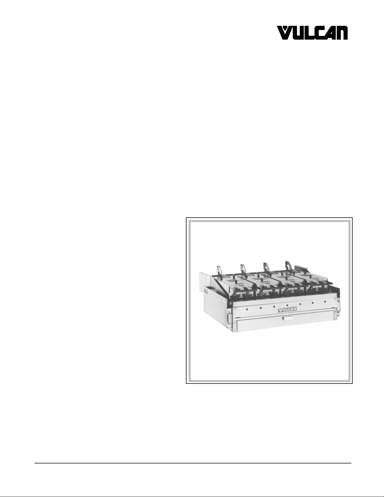
GDC SERIES GAS DUPLEX COOKERS
MODELS
GDC24 ML-52581
GDC36 ML-52582
GDC48 ML-52583
GDC60 ML-52584
GDC72 ML-52585
MODEL GDC48
VULCAN-HART COMPANY, P.O. BOX 696, LOUISVILLE, KY 40201-0696, TEL. (502) 778-2791
FORM 30501 (Rev. A, 11-95)
Page 2
IMPORTANT FOR YOUR SAFETY
THIS MANUAL HAS BEEN PREPARED FOR PERSONNEL QUALIFIED TO INSTALL GAS
EQUIPMENT, WHO SHOULD PERFORM THE INITIAL FIELD START-UP AND
ADJUSTMENTS OF THE EQUIPMENT COVERED BY THIS MANUAL.
POST IN A PROMINENT LOCATION THE INSTRUCTIONS TO BE FOLLOWED IN THE
EVENT THE SMELL OF GAS IS DETECTED. THIS INFORMATION CAN BE OBTAINED
FROM THE LOCAL GAS SUPPLIER.
IMPORTANT
IN THE EVENT A GAS ODOR IS DETECTED, SHUT
DOWN UNITS AT MAIN SHUTOFF VALVE AND
CONTACT THE LOCAL GAS COMPANY OR GAS
SUPPLIER FOR SERVICE.
FOR YOUR SAFETY
DO NOT STORE OR USE GASOLINE OR OTHER
FLAMMABLE VAPORS OR LIQUIDS IN THE
VICINITY OF THIS OR ANY OTHER APPLIANCE.
WARNING
IMPROPER INSTALLATION, ADJUSTMENT,
ALTERATION, SERVICE OR MAINTENANCE CAN
CAUSE PROPERTY DAMAGE, INJURY OR DEATH.
READ THE INSTALLATION, OPERATING AND
MAINTENANCE INSTRUCTIONS THOROUGHLY
BEFORE INSTALLING OR SERVICING THIS
EQUIPMENT.
IN THE EVENT OF A POWER FAILURE, DO NOT
ATTEMPT TO OPERATE THIS DEVICE.
© VULCAN-HART COMPANY, 1989
— 2 —
Page 3

Installation, Operation and Care of
GDC SERIES GAS DUPLEX COOKERS
KEEP THESE INSTRUCTIONS FOR FUTURE USE
GENERAL
The GDC Series Gas Duplex Cookers combine a high efficiency gas griddle with adjustable-height,
thermostat-controlled electric platens to provide fast production of grilled foods. Vulcan Duplex
Cookers are produced with quality workmanship and material. Proper installation, usage and
maintenance will result in many years of satisfactory performance.
It is suggested that you thoroughly read this entire manual and carefully follow all of the instructions
provided.
INSTALLATION
Before installing, verify that the type of gas (natural or propane), the elevation, and the electrical service
agree with the specifications on the rating plate, located on the left side panel.
UNPACKING
This cooker was carefully inspected before leaving the factory. The transportation company assumes
full responsibility for safe delivery upon acceptance of the shipment. Immediately after unpacking,
check for possible shipping damage. If the cooker is found to be damaged, save the packaging material
and contact the carrier within 15 days of delivery.
CAUTION: Lower all platens before attempting to move this cooker.
LOCATION
The installation location must be kept free and clear of combustibles. Clearances from combustible
and non-combustible construction must be a minimum of 7 inches from the sides and 2 inches from
the back. A minimum front clearance of 32 inches is required for service and operation.
Sufficient air should be allowed to enter the room to compensate for the amount of air removed by any
ventilating system and for combustion of the gas burners. Do not permit fans to blow directly on the
cooker. Avoid open windows at the sides or back. Avoid wall-type fans which create air cross currents
within the room. Do not obstruct the air flow into and around the cooker. Do not obstruct the flow of
flue gases from the flue duct (when so equipped). It is recommended that the flue gases be ventilated
to the outside of the building through a suitable and properly installed ventilation system.
— 3 —
Page 4

INSTALLATION CODES AND STANDARDS
The GDC Series Gas Duplex Cookers must be installed in accordance with:
In the United States:
1. State and local codes.
2. National Fuel Gas Code ANSI Z223.1 (latest edition), available from American Gas Association,
1515 Wilson Blvd., Arlington, VA 22209.
3. National Electrical Code ANSI NFPA No. 70 (latest edition), and with NFPA Standard No. 96, Vapor
Removal from Cooking Equipment (latest edition), available from the National Fire Protection
Association, Batterymarch Park, Quincy, MA 02269.
In Canada:
1. Local codes.
2. CAN/CGA-B149.1 Installation for Natural Gas Burning Appliances and Equipment (latest edition).
3. CAN/CGA-B149.2 Installation for Propane Burning Appliances and Equipment (latest edition),
available from The Canadian Gas Association, 55 Scarsdale Road, Don Mills, Ontario, Canada
M3B2R3.
4. Canadian Electrical Code Part 2, CSA Standard C22.1 (latest edition).
ASSEMBLY
Legs
The duplex cooker is shipped as a complete unit and does not require field assembly except the
supporting legs or stand. Screw the legs on the four corners of the cooker, into the welded nuts. Hand
tighten the legs and set in place.
Casters (Optional)
If the cooker is equipped with casters, the gas connector (available from Vulcan-Hart) must comply with
the Standard for Connectors of Movable Gas Appliances, ANSI-Z21.69 (latest edition), and a quickdisconnect device that complies with the Standard for Quick-Disconnect Devices for Use With Gas
Fuel, ANSI-Z21.41 (latest edition).
When casters are installed, provide a restraining device for the gas line to limit movement of the cooker
without depending on the connector and/or any quick-disconnect device or its associated piping to limit
cooker movement. Attach the restraining device to a rear leg of the stand.
If it is necessary to disconnect the restraint, turn off the gas supply before disconnection. Reconnect
the restraint before turning the gas supply on and returning the cooker to its installation position.
Instructions for installing casters to the cooker are included with the casters.
— 4 —
Page 5
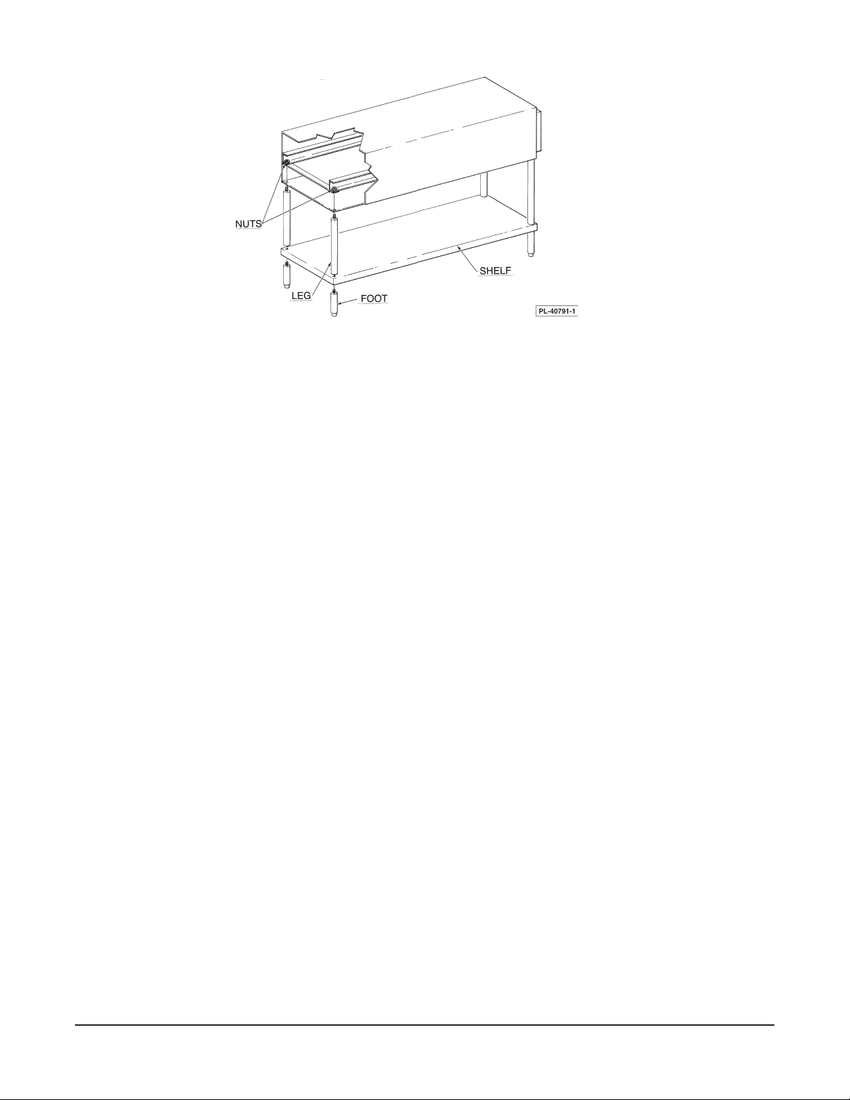
Fig. 1
Stand (Fig. 1)
1. Thread leg extension into fixed nut in griddle frame.
2. Thread adjustable leg through undershelf into leg extension.
3. Tighten both leg extension and adjustable legs.
4. If casters are furnished instead of adjustable legs, the locking swivel casters must be placed in the
front.
5. To level the griddle plate, turn the adjustment screw at the bottom of each leg.
GAS CONNECTIONS
Make the gas connection to the appropriate location on the cooker according to applicable codes.
Make sure the pipes are clean and free of obstructions, dirt, and piping compound.
CAUTION: All gas supply connections and any pipe joint compound must be a type that is
resistant to the action of liquified petroleum gases.
Codes require that a gas shutoff valve be installed in the gas line ahead of the duplex cooker.
WARNING: PRIOR TO LIGHTING, CHECK ALL JOINTS IN THE GAS SUPPLY LINE FOR LEAKS.
USE SOAP AND WATER SOLUTION. DO NOT USE AN OPEN FLAME.
After piping has been checked for leaks, fully purge gas pipes to remove air.
TESTING THE GAS SUPPLY PIPING SYSTEM
1
When test pressures exceed
/2 psig (3.45 kPa), the cooker and its individual shutoff valve must be
disconnected from the gas supply piping system.
— 5 —
Page 6

When test pressures are 1/2 psig (3.45 kPa) or less, the cooker must be isolated from the gas supply
piping system by closing its individual shutoff valve.
ELECTRICAL CONNECTIONS
Make supply connections using insulated copper wire suitable for at least 90°C for the rated load.
When initially selecting conduit size, keep in mind the possibility of additional platens being added to
the duplex cooker at a later date.
The electrical diagram is attached to the hinged control panel cover.
Permanently Connected Duplex Cookers
WARNING: ELECTRICAL AND GROUNDING CONNECTIONS MUST COMPLY WITH THE
APPLICABLE PORTIONS OF THE NATIONAL ELECTRICAL CODE AND/OR OTHER LOCAL
ELECTRICAL CODES.
WARNING: DISCONNECT ELECTRICAL POWER SUPPLY AND PLACE A TAG AT THE
DISCONNECT SWITCH TO INDICATE THAT YOU ARE WORKING ON THE CIRCUIT.
Cord Connected Duplex Cookers
WARNING: THE SUPPLY CORD ON THE GAS DUPLEX COOKER IS PROVIDED WITH A THREE-
PRONG GROUNDING PLUG. IT IS IMPERATIVE THAT THIS PLUG BE CONNECTED INTO A
PROPERLY GROUNDED THREE-PRONG RECEPTACLE. IF THE RECEPTACLE IS NOT THE
PROPER GROUNDING TYPE, CONTACT AN ELECTRICIAN. DO NOT REMOVE THE GROUNDING
PRONG FROM THIS PLUG.
ELECTRICAL DATA
Total Total Loading KW Nominal Amps./Line Circuit
Platens
Per Conn. 240V 3 Ph. 208V 3 Ph. 3 Ph. 1 Ph. 3 Ph. 1 Ph. 240V 208V
GDC 240V 208V L1-L3 L2-L3 L1-L3 L1-L2 L2-L3 L1-L3 L1 L2 L3 L1-L3 L1 L2 L3 L1-L3 3Ph. 1Ph. 3Ph. 1Ph.
1 2.67 2 2.67 0 0 2 0 0 10 10 0 11 9 9 0 10 15 15 15 15
2 5.34 4 2.67 2.67 0 2 2 0 10 20 10 26 9 17 9 19 25 35 25 25
3 8.01 6 2.67 2.67 2.67 2 2 2 20 20 20 34 17 17 17 29 25 45 25 40
4 10.68 8 2.67 2.67 5.34 2 2 4 29 20 29 45 25 17 25 39 40 60 35 50
5 13.35 10 5.34 2.67 5.34 4 2 4 39 20 39 56 34 17 34 48 50 70 45 60
6 16.02 12 5.34 5.34 5.34 4 4 4 39 39 39 67 34 34 34 58 50 90 45 80
KW Per Phase 240V 208V Size *
* MINIMUM CIRCUIT AMPACITY AND MAXIMUM CIRCUIT BREAKER SIZE (AMPS.) compiled in
accordance with The National Electrical Code (latest edition).
— 6 —
Page 7

OPERATION
WARNING: THE DUPLEX COOKER AND ITS PARTS ARE HOT. BE CAREFUL WHEN OPERATING,
CLEANING, AND SERVICING THE DUPLEX COOKER.
CONTROLS (Fig. 2)
Each griddle zone, one foot wide, and each platen has its own separate controls.
TOP - SIDE
TWIN - CAM FEET
COOKER HANDLE
PLATEN
GRIDDLE
SURFACE
GREASE
TROUGH
THERMOSTAT
AMBER LIGHT
MAIN ON / OFF SWITCH
ON / OFF SWITCH
TOP- SIDE COOKER CONTROLS
Fig. 2
GREASE
CONTAINER
GRIDDLE
CONTROLS
PL-40792-1
Main On-Off Switch — controls power to the pilot igniters.
On-Off Switch with indicator light — controls power to the thermostat/heater circuit.
Black Thermostat — controls griddle heaters (150-450° F). Each zone is one
foot wide.
Amber Light — indicates heat is being supplied to satisfy the thermostat.
Red Thermostat — controls heater to each platen (150-350°F).
Fuse — replace with same size and type.
Twin-Cam Feet — sets distance of the platen from the griddle surface. (Marked
1
settings 3 - 16 are equivalent to
intermediate divisions allow settings from
/16" divisions. Unmarked
5
/32" to 1" in
32nds.)
Handle — lift handle to access griddle area.
— 7 —
Page 8

BEFORE FIRST USE
The griddle plate is shipped with a protective coating. Remove this coating before cooking with griddle.
Clean the griddle with a damp cloth and mild detergent. Rinse with a clean damp cloth and wipe dry.
The griddle must be seasoned prior to first use. See the section titled SEASON GRIDDLE SURFACE
for seasoning procedure.
LIGHTING PILOTS ON GRIDDLES WITH ELECTRIC IGNITION
CAUTION: Do not turn the electric supply on without making sure the gas is flowing to the pilots.
Failure to do this may shorten igniter life.
1. Turn all burner valves OFF. Wait 5 minutes to allow any gas to escape.
2. Turn the gas supply ON.
3. Turn the main electric switch ON. The red light comes on.
4. Pilots should light as soon as the gas supply reaches the pilot. Verify this before proceeding to
normal operation.
If pilot goes out, the electric igniter will relight the pilot.
If electricity to the griddle goes off, gas supply to the pilots and to the burners is automatically shut off.
NORMAL OPERATION
A red thermostat on the front control panel regulates the temperature of each platen and has a separate
on-off switch.
Twin radial cams adjust height of the platen above the griddle for optimal cooking performance.
5
Gradations from
/32" to 1" in 32nds are available with markings from 3/16" to 16/16" or 1".
A black thermostat on the front control panel regulates the temperature of each foot-wide section of
griddle surface.
1. Follow procedure for lighting pilots before proceeding.
2. Adjust radial cams on platens for height of platen.
3. Turn switch ON and set thermostat to desired temperature. Amber light flashes on when heating,
off when thermostat is satisfied.
4. Repeat step 3 for all sections of the griddle and all platens.
— 8 —
Page 9

PREHEAT GRIDDLE
CAUTION: Care must be exercised not to overheat the griddle plate by setting the thermostats
well above recommended temperatures. Overheating the plate may cause plate warpage, and
will carbonize any grease on the plate and cause sticking.
1. Set thermostat to desired griddle temperature. Burners should light.
2. Allow 15-20 minutes for the griddle temperature to reach thermostat setting.
3. When amber light first flashes off, griddle is ready to be seasoned, or if previously seasoned, for
loading.
SEASON GRIDDLE SURFACE
Unless the product contains sufficient fat, the griddle surface must be seasoned before each cooking
operation. Surface must also be seasoned after each thorough cleaning.
1. Preheat the griddle to 400°F.
2. When the amber light goes off, spread a film of cooking oil or fat over the entire cooking surface
of the lower griddle.
3. In two minutes, scrape the surface clean of surplus oil. Repeat steps 2 and 3.
4. The griddle is now ready for use.
This griddle plate is steel, but the surface is relatively soft and can be scored or dented by carelessly
using a spatula. Be careful not to dent, scratch, or gouge the plate surface. Do not try to knock off loose
food that may be on the spatula by tapping the corner or edge of the spatula on the griddle surface.
AT THE END OF THE DAY
Turn the Main On-Off switch to OFF. The pilot, igniter red light and thermostat will be turned off.
TO SHUT OFF FOR AN EXTENDED PERIOD
Turn both the electric supply and gas supply OFF.
CLEANING THE GRIDDLE
WARNING: DISCONNECT ELECTRICAL POWER SUPPLY BEFORE CLEANING.
To produce evenly cooked, browned products, keep the griddle free of carbonized grease. Carbonized
grease may cling to the griddled foods, giving them an unsatisfactory appearance.
— 9 —
Page 10

After Each Use
Clean the griddle with a flexible spatula or griddle scraper. Take care not to contact the platen surfaces
as these can be easily scratched, shortening the life of the coating and promoting sticking.
During The Day
Flush the hot griddle with water and scrape with griddle scraper to reduce carbonized grease build-up.
Follow by a light coating of oil to prevent product sticking.
Periodically inspect the grease container. As necessary, remove the grease container, empty it, and
wash it out in the same manner as any ordinary cooking utensil.
Once A Day
Thoroughly clean backsplash, sides and front. Take care that the integral backsplash is not vigorously
banged with a spatula.
Thoroughly clean and wipe out grease trough in front of griddle. As necessary during use, wipe out
accumulated material to provide good drainage.
Clean the griddle surface thoroughly with water and degreasing cleaner. Rub with the grain of the metal
while the griddle is still warm (not hot). Ensure that the degreasing cleaner is thoroughly removed by
flushing with clear water.
Clean stainless steel and chrome surfaces with a damp cloth and polish with a soft dry cloth. To remove
discolorations, use a non-abrasive cleaner. After each cleaning, the griddle must be reseasoned.
CARE AND CLEANING OF THE PLATEN
The platen surface is furnished with a special non-stick coating. After each use, wipe the surface with
a soft cloth moistened with water. Harsh chemicals or abrasive materials must never touch the surface
of the platen.
Clean platen after each heavy cooking period. Never allow platen to remain uncleaned for extended
periods of time. Cooking residue will become hard, making clean-up difficult.
Do not scrape with spatula or grill scraper. Use a soft damp clean cloth only.
If platen will not be used during low volume hours, wipe the platen with a soft clean damp cloth.
When you shut the griddle down for end-of-day cleaning, clean the platen with a little water and a soft
clean damp cloth.
• DO - Use a soft clean damp cloth.
•DO - Use water only as a cleaning agent.
• DO NOT - Scrape the platen surface with a spatula, grill scraper or any other hard object. It is not
necessary.
— 10 —
Page 11

• DO NOT - Use grill cleaners on the platen.
Life of the non-stick coating of the platen will vary depending upon the product cooked and the cooking
temperature, but its life can be extended by frequent cleaning and by using care not to scratch the
surface.
When sticking of product eventually occurs and cannot be eliminated by thorough cleaning with a soft
cloth and water, it will be necessary to replace the platen surface (see MAINTENANCE).
Care of the Stainless Steel Housing
The outside stainless steel portion of the platen can be cleaned with a mild detergent and stainless steel
polish.
MAINTENANCE
WARNING: THE DUPLEX COOKER AND ITS PARTS ARE HOT. BE CAREFUL WHEN OPERATING,
CLEANING OR SERVICING THE DUPLEX COOKER.
WARNING: TURN OFF ALL ELECTRIC AND GAS CONTROLS AND ALLOW TO COOL BEFORE
PERFORMING ANY MAINTENANCE.
The following routine maintenance is suggested.
1. Burner air shutter openings must be kept clean.
2. Burner ports must be kept clean. To clean burners, boil them in a detergent and water solution for
15 to 20 minutes. Then either brush with a wire brush or clean gas ports with a sharp pointed metal
instrument to ensure open ports.
3. Burner pilot flash tubes and burner ignition port must be clear for burners to ignite properly from
the pilot.
4. Check the flue for obstructions on an annual basis.
5. To recalibrate the thermostat, contact your Vulcan-Hart authorized servicer.
REPLACEMENT OF THE PLATEN SURFACE
Contact your Vulcan-Hart authorized servicer for replacement kits for platen surfaces.
— 11 —
Page 12

Tools required:
7
/16 socket (magnetic) 1/4 drive
1
/4 drive universal joint
1
/4 drive 6" extension
1
/4 drive ratchet
1. Remove platen cover (Fig. 3).
2. Remove all bolts from platen. Remove platen surface. (Fig. 4)
Fig. 3 Fig. 4
3. Clean surface thoroughly. Make sure all foreign particles are removed from both surfaces (Fig. 5).
1
4. Attach new surface to platen with new (10) short and (2) long
/4-20 special bolts and (12) 1/4-20
locknuts. Tighten all bolts and nuts finger tight. (Fig. 6)
Fig. 5 Fig. 6
— 12 —
Page 13

5. Tighten all bolts and nuts firmly (do not overtighten), with 7/16 wrench, in numerical order as shown
in the diagram (Fig. 7). CAUTION: Overtightening can deform the aluminum material of the
platen.
The holes in the platen surface and the heads on the special bolts are eccentric. Make sure the
head of each bolt fits into the hole in the platen surface and stays there until the nut is finger
tightened.
6. Reinstall platen cover (Fig. 8)
Fig. 7 Fig. 8
SERVICE AND PARTS INFORMATION
To obtain service and parts information concerning this duplex cooker, contact the Vulcan-Hart Service
Agency in your area (refer to listing supplied with the duplex cooker), or Vulcan-Hart Company Service
Department at the address or phone number shown on the front cover of this manual.
— 13 —
Page 14

TROUBLESHOOTING
PROBLEM
Red light won't come on when main switch is on.
Red light won't go off when Main On-Off or Thermostat
switch is on.
Cooker fails to heat when Thermostat On-Off switch
is on.
Igniter stays on too long after pilot flame is established.
POSSIBLE CAUSE
Not plugged in.
Problem with On-Off switch.
Building circuit breaker tripped.
Problem with lamp in switch.
Problem with On-Off switch.
Cooker not plugged in.
Problem with Main On-Off switch.
Building circuit breaker tripped.
Problem with Thermostat On-Off switch.
Problem with pilot valve.
Problem with igniter.
Problem with flame switch.
Loose wiring connections.
Flame switch has not had enough time to heat up.
Flame switch bulb not hot enough.
a. Problem with alignment of pilot and flame switch.
b. Obstructed or wrong size pilot orifice.
c. Gas pressure too low.
Problem with flame switch.
Igniter fails to light.
Pilot does not light after igniter has been on several
minutes.
Pilot fails to remain lit after igniter goes out. (Pilot
may cycle on and off normally several times after cold
start-up before the pilot heats up.)
Burner doesn't come on; amber light doesn't come
on.
Problem with igniter.
Cooker not plugged in.
Building circuit breaker tripped.
Problem with Main On-Off switch.
Loose wiring connection.
Problem with pilot valve.
Gas supply not purged of air or no gas supply.
Loose wiring connection.
Obstructed or wrong size pilot orifice.
Pilot adjustment valve closed.
Problem with alignment of pilot and igniter.
Loose wiring connection.
Obstructed or wrong size pilot orifice.
Pilot adjustment valve closed.
Problem with alignment of pilot and flame switch.
Problem with flame switch.
Thermostat setting too low.
Problem with remote set-pot.
Problem with thermistor sensor.
Problem with temperature controller.
Problem with thermostat gas valve.
Loose wiring connection.
— 14 —
Page 15

PROBLEM
POSSIBLE CAUSE
Heat doesn't turn off; amber light is off; temperature
is above thermostat setting.
Heat doesn't turn off; amber light is on; temperature
is above thermostat setting.
Fat appears to smoke excessively.
Food undercooked inside.
Food tastes greasy or has objectional off-flavor.
Noticeable build-up of gum on griddle.
Problem with thermostat gas valve.
Problem with temperature controller.
Problem with remote set-pot.
Temperature set too high.
Moisture in food may be turning into steam.
Griddle surface needs cleaning and/or seasoning.
Surface under food may not have been covered with
enough cooking oil.
Temperature set too high.
Food not cooked long enough.
Food itself may have off-flavor.
Food may have been stored improperly before
cooking.
Too much griddle fat used.
Temperature set too low.
Temperature set too high.
Griddle surface needs cleaning and/or seasoning.
— 15 —
Page 16

FORM 30501 (Rev. A, 11-95)
— 16 —
 Loading...