

Page 1
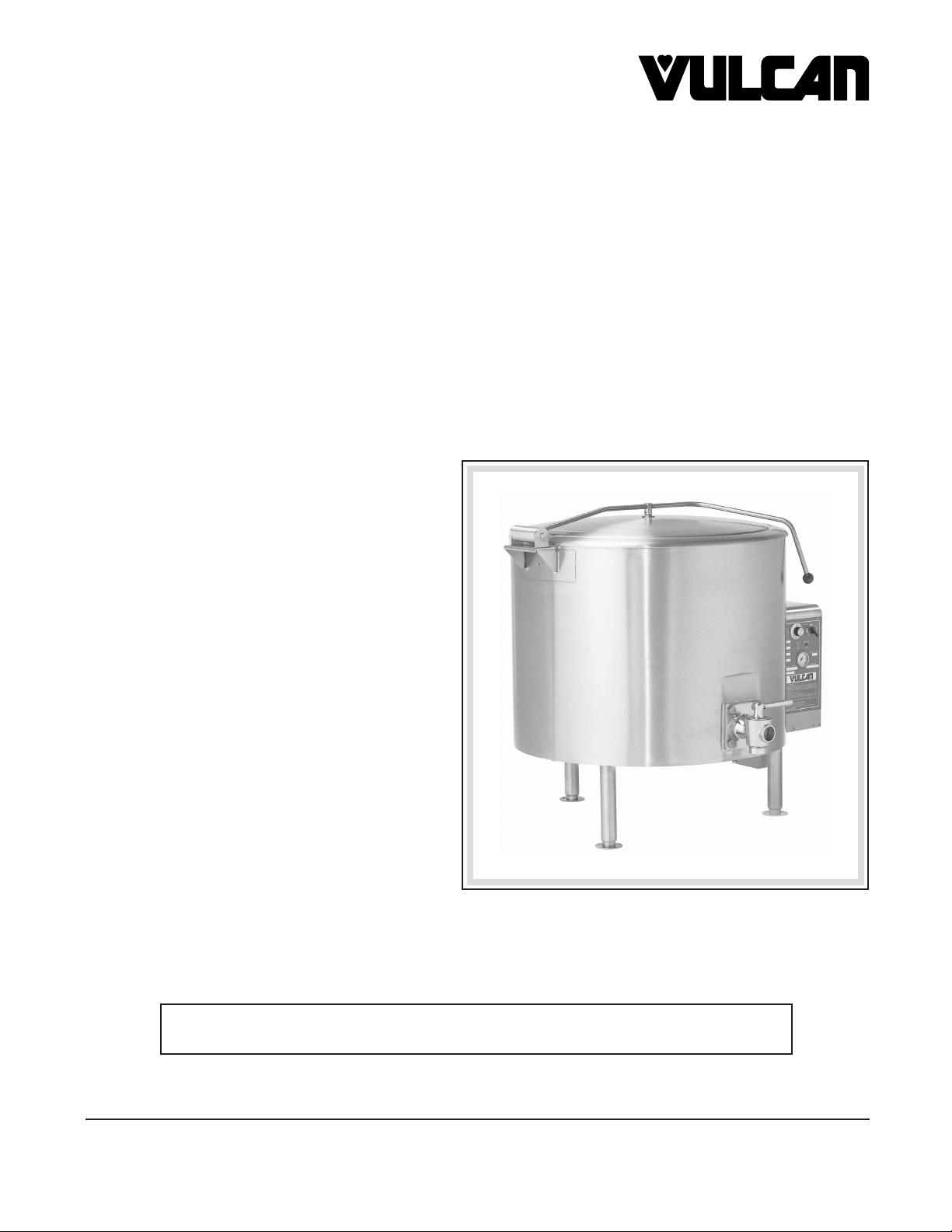
INSTALLATION , OPERATION
SERVICE & PARTS MANUAL
ES, EL & ET STEAM JACKETED KETTLES
MODELS
ES25 ML-52642
ES30 ML-52643
EL40 ML-52644
ES60 ML-52645
EL80 ML-52646
ET100 ML-52647
ET125 ML-52648
ET150 ML-52649
For additional information on Vulcan-Hart Company or to locate an authorized
parts and service provider in your area, visit our Web site at www.vulcanhart.com
VULCAN-HART COMPANY, P.O. BOX 696, LOUISVILLE, KY 40201-0696, TEL. (502) 778-2791
FORM 30965 Rev. A (06-03)
Page 2

TABLE OF CONTENTS
GENERAL.............................................................................................................................................................. 3
INSTALLATION .....................................................................................................................................................3
Unpacking .................................................................................................................................................3
Location ....................................................................................................................................................3
Leveling .................................................................................................................................................... 3
Installation Codes and Standards ...........................................................................................................3
Electrical Connections .............................................................................................................................4
Faucet Connection (Optional) ................................................................................................................. 4
OPERATION .........................................................................................................................................................5
Before First Use .......................................................................................................................................5
Controls .................................................................................................................................................... 5
Filling the Water Jacket ...........................................................................................................................6
Using the Kettle ........................................................................................................................................6
Kettle Food Draw-Off Valve .....................................................................................................................6
Cleaning.................................................................................................................................................... 6
MAINTENANCE ....................................................................................................................................................8
Periodic Maintenance .............................................................................................................................. 8
Pressure Relief Valve ............................................................................................................... 8
Low Water Cut-Off ....................................................................................................................8
Sight Glass Assembly............................................................................................................... 8
Draw-Off Valve .......................................................................................................................... 8
Vent ........................................................................................................................................... 8
Kettle Jacket Fluid ....................................................................................................................8
SERVICE ............................................................................................................................................................... 9
General Notes ..........................................................................................................................................9
Servicing Procedures ............................................................................................................................... 9
Thermostat ................................................................................................................................9
Low Water Cut-Off ..................................................................................................................10
Pressure Limit Switch .............................................................................................................10
Magnetic Contactor ................................................................................................................. 10
Electric Heating Elements ......................................................................................................10
Replace On-Off Switch ........................................................................................................... 11
Replace Signal Light ............................................................................................................... 11
Replace Pressure Gauge .......................................................................................................11
Correct Leaking Draw-Off Valve ............................................................................................11
Service and Parts Information ............................................................................................................... 11
PARTS LIST ........................................................................................................................................................ 12
WIRING DIAGRAMS...........................................................................................................................................14
DIMENSIONS AND SERVICE CONNECTIONS ...............................................................................................18
© VULCAN-HART COMPANY, 2003
– 2 –
Page 3

Installation, Operation and Care of
MODEL ES, EL & ET STEAM JACKETED KETTLES
KEEP THESE INSTRUCTIONS FOR FUTURE REFERENCE
GENERAL
Your Vulcan steam jacketed kettle is produced with quality workmanship and material. Proper
installation, usage and maintenance will result in many years of satisfactory performance.
Vulcan-Hart Company suggests that you thoroughly read this entire manual and carefully follow all of
the instructions provided.
INSTALLATION
Prior to installation verify that the electrical service agrees with the specifications on the machine data
plate located inside the front cover at the lower left.
UNPACKING
This kettle was inspected before leaving the factory. The transportation company assumes full
responsibility for safe delivery upon acceptance of the shipment. Immediately after unpacking, check
for possible shipping damage. If the kettle is found to be damaged, save the packaging material and
contact the carrier within 15 days of delivery.
LOCATION
Position the kettle in its final location. Check that there are sufficient clearances for operating and
servicing the kettle, and for proper clearance of the cover when raised. The kettle draw off faucet should
be located near a floor drain.
LEVELING
Place a spirit level on the rim of the kettle with the cover open. Adjust the feet to level the kettle leftto-right and front-to-back.
INSTALLATION CODES AND STANDARDS
Vulcan kettles must be installed in accordance with:
In the United States:
1. Local codes.
2. National Electrical Code ANSI/NFPA-70 (latest edition).
– 3 –
Page 4
3. ANSI NFPA Standard #96 "Vapor Removal from Cooking Equipment," (latest edition), available
from the National Fire Protection Association, Batterymarch Park, Quincy, MA 02269.
In Canada:
1. Local codes.
2. CSA Standard C22.1 Canadian Electrical Code, Part 1.
ELECTRICAL CONNECTIONS
WARNING: ELECTRICAL AND GROUNDING CONNECTIONS MUST COMPLY WITH THE
APPLICABLE PORTIONS OF THE NATIONAL ELECTRICAL CODE AND/OR OTHER LOCAL
ELECTRICAL CODES.
WARNING: DISCONNECT ELECTRICAL POWER SUPPLY AND PLACE A TAG AT THE
DISCONNECT SWITCH TO INDICATE THAT YOU ARE WORKING ON THE CIRCUIT.
Make required electrical supply connections at the junction box located below the control box. There
is no opening in the junction box for supply line conduit. The box is a sealed box and the conduit
connection should be made with fittings of the water resistant type. Be sure the supply wiring and the
circuit protection are adequate for the K.W. load drawn by the kettle. The wiring diagram is located on
the back side of the removable control cover. Use copper wire suitable for at least 75°C temperature.
If the kettle is for operation on an electric supply of over 240 volts, a transformer is provided to reduce
the control circuit voltage to 120 volts.
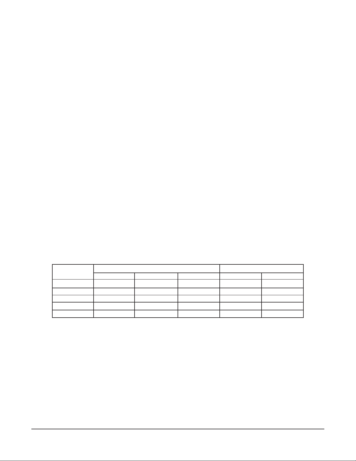
ELECTRICAL DATA CHART
NOMINAL AMPS PER LINE WIRE
3 PHASE 1 PHASE
K.W. 208 230-240 440-460-480 208 230-240
12 33.4 28.9 14.5 57.6 50.0
18 50.0 43.4 21.7 86.5 75.0
24 66.7 57.8 28.9 115.4 100.0
36 100.0 86.8 43.4 — —
43.2 119.9 104.0 52 — —
Each of the two elements draws one-half of the above listed total amperage.
FAUCET CONNECTION (Optional)
If the optional faucet assembly is to be installed, connect as required.
– 4 –
Page 5

OPERATION
WARNING: THE KETTLE AND ITS PARTS ARE HOT. USE CARE WHEN OPERATING, CLEANING
AND SERVICING THE KETTLE.
BEFORE FIRST USE
Using a non-corrosive, grease-dissolving commercial cleaner, clean the protective metal oils from all
surface parts and interior of the kettle. Follow the cleaner manufacturer's directions. Rinse thoroughly
with warm water to remove all traces of the cleaner. Drain the kettle. Wipe dry with a soft clean cloth.
CONTROLS
On-Off Switch — Turns power to the kettle on or off.
Thermostat Switch, — These three switches are wired in series and control the supply of
Low Water Cutoff Switch, energy to the heating elements. Opening any one of these pressure
Limit Switch switches will shut off the power supply to the heating elements.
Thermostat — Senses the temperature in the steam jacket. At a dial setting of 5 to
6, it will cut power off as the pressure gauge needle moves off zero.
The higher dial settings
holding. At the higher dial settings,
jacket will drop to 2 to 2
off and before it cuts it on.
are for cooking, the lower ones for
1
/2 psi after the thermostat cuts the power
the steam pressure in the
Low Water Cutoff Switch — Cuts off power to the heating elements if the jacket distilled water
level is too low.
Pressure Relief Valve, — Protect the kettle against excessive pressure should the thermostat
Pressure Limit Switch
Pressure Gauge — Indicates pressure in the jacket.
Sight Glass Assembly — Visually shows the distilled water depth in the steam jacket.
Thermostatic Air Vent —
Fill Assembly — Location for adding distilled water to the jacket. It is equipped with
Food Draw-Off Valve — Allows food and liquid to be drawn off from the kettle.
malfunction. The pressure relief valve is rated so that it will
relieve
generate it.
Lets air out of jacket as steam is generated; closes at
approximately 180°F to prevent the steam from escaping.
a manual valve plus a check valve to prevent a discharge should the
manual valve be inadvertently opened while the jacket is under
pressure.
generated steam faster than the heating elements can
– 5 –
Page 6

FILLING THE WATER JACKET
APPLIANCE FAILURE CAUSED BY INADEQUATE WATER QUALITY IS NOT COVERED UNDER
WARRANTY.
Fill the outer jacket of the kettle to the top of the band on the gauge glass with a chemically pure distilled
water, along with a suitable rust inhibitor.
It should not be necessary to frequently add distilled water to the jacket, as little distilled water is lost
in normal operation.
USING THE KETTLE
Before use, preheat the kettle empty. Set the thermostat at No. 12 or No. 13. When the orange light
goes out, load food and set thermostat dial for desired cooking temperature.
KETTLE FOOD DRAW-OFF VALVE
When the food draw-off valve is turned off (no liquid or food product flow), the valve handle will point
to either the 9 o'clock or 3 o'clock position. To open (allowing liquid or food product flow), slowly pull
handle forward. With the valve handle pointing to the 6 o'clock position, the valve is in a fully open
position. This food draw-off valve system requires a right or left turn to close off food flow.
To allow for evenly mixed food products to flow into a food service pan or stock pot, first thoroughly stir
the food product in the kettle before opening the food draw-off valve. Pans or pots may be placed on
a portable dolly for easy movement and handling.
CLEANING
WARNING: DISCONNECT ELECTRICAL POWER SUPPLY BEFORE CLEANING.
After Each Use
Clean and flush the kettle immediately after each use, especially if the product cooked contained salt
or vinegar in any concentration.
Daily — Kettle Food Draw-Off Valve
1. With kettle empty, pull valve handle to the 7 o'clock position. (A pin locks the valve plug into the
valve body and you can only remove or replace the valve plug when the valve handle is in the
7 o'clock position.) Kettles built before July 2003 thru March 1992 - the removable position is at 4
o'clock. Kettles built prior to March 1992 - the removable position is at 6 o'clock.
2. Pull tapered plug from valve body.
3. Using warm soapy water, wash the entire valve body and open area into the kettle interior.
4. Wash the interior and exterior of the valve plug. CAUTION: Do not drop or hit the valve plug.
This will nick or dent the soft metal.
– 6 –
Page 7

5. After washing, lubricate the valve body and valve plug with Petro-Gel lubricant. Make sure all
interior mating surfaces are covered with this lubrication. This lubrication must be done every day
after use. If the food draw-off valve plug and inside of valve body are not lubricated, undesirable
leakage can occur, or the valve plug could stick in a partially open position when the kettle is up
to cooking temperature and the operator attempts to open the draw-off valve.
A 4-ounce tube of Petro-Gel is furnished with your kettle. You can reorder through your local service
agency or food service equipment dealer.
6. Each draw-off valve body and removable tapered draw-off plug is stamped with a set of corresponding
numbers. After cleaning and lubricating, make sure the body and plug numbers match before
reinserting the tapered plug.
7. Examine the valve plug and valve body for nicks and deep scratches. Do not attempt to push or
force the valve plug into the valve body if there are any obstructions, nicks, or deep scratches in
either the plug or body. Contact your local Vulcan authorized servicer.
8. Carefully slide the valve plug into the valve body. CAUTION: Do not attempt to slide valve plug
into valve body when valve handle is at any other than the 7 o'clock position. This will damage
the pin and the plug will not seat properly, causing leakage between the valve body and plug.
Kettles built before July 2003 thru March 1992 - the removable position is at 4 o'clock. Kettles built
prior to March 1992 - the removable position is at 6 o'clock.
Sight Glass Assembly
This component indicates the distilled water level inside the jacket and should be checked at least once
a day. The correct distilled water level is a point one-half the height of the glass. Extreme murkiness
indicates that the kettle jacket should be cleaned.
– 7 –
Page 8

MAINTENANCE
WARNING: THE KETTLE AND ITS PARTS ARE HOT. USE CARE WHEN OPERATING, CLEANING
AND SERVICING THE KETTLE.
WARNING: DISCONNECT ELECTRICAL POWER SUPPLY AND PLACE A TAG AT THE
DISCONNECT SWITCH TO INDICATE THAT YOU ARE WORKING ON THE CIRCUIT.
PERIODIC MAINTENANCE
1. Pressure Relief Valve
This protection device should be opened at least once a day to avoid lime build-up. Replace if
leakage occurs or it opens below rated p.s.i.
2. Low Water Cut-Off
This device should be removed and inspected for lime build-up at least once a year. The float must
move freely in its cage. Clean if necessary. Replace if lime or sludge cannot be removed to allow
the float to move freely.
3. Sight Glass Assembly
This unit indicates the distilled water level inside the jacket and should be checked at least once
a day. The correct distilled water level is a point one-half the height of the glass. Extreme murkiness
indicates the kettle jacket should be cleaned.
4. Draw-Off Valve
The faces of this valve should be lubricated with Petro-Gel daily to prevent sticking.
5. Vent
Annually, when cool, check the air vent and clear any obstructions.
6. Kettle Jacket Fluid
Draining the water from the jacket (or flushing the jacket) is not required or desirable at frequent
intervals and should be done only when there is evidence of scale or sludge inside the jacket.
To drain the jacket, remove the drain plug on the exterior bottom plate of the kettle.
The jackets are constructed of type 304 stainless steel, but they can pit and corrode under adverse
conditions. Prompt, careful cleaning will help prevent this. To clean and flush the jacket, remove
the low water cutoff switch and insert a water hose through this opening. When the jacket is refilled,
always use chemically pure water, along with two ounces of a boiler feed water treatment
compound. A 6-ounce bottle of treatment compound is available from Vulcan-Hart.
– 8 –
Page 9

SERVICE
WARNING: THE KETTLE AND ITS PARTS ARE HOT. USE CARE WHEN OPERATING, CLEANING
AND SERVICING THE KETTLE.
WARNING: DISCONNECT ELECTRICAL POWER SUPPLY AND PLACE A TAG AT THE
DISCONNECT SWITCH TO INDICATE THAT YOU ARE WORKING ON THE CIRCUIT.
GENERAL NOTES
The signal light marked "Power On" glows when the On-Off switch is turned to ON, and electric power
is supplied to the kettle.
The signal light marked "Heat On" glows when the thermostat switch is closed (thermostat calling for
heat).
The thermostat, with the dial at the highest setting, should cut the power off at a jacket pressure of
12 to 13 p.s.i. and before the pressure relief valve opens.
The pressure limit switch is set to open when the jacket pressure reaches 15 p.s.i. and to close when
jacket pressure drops to 6 p.s.i.
The On-Off switch is a two-pole switch and opens both lines of the control circuit. The thermostat
switch, the low water cut-off switch and the pressure limit switch are single-pole switches.
SERVICING PROCEDURES
WARNING: DISCONNECT ELECTRICAL POWER SUPPLY AND PLACE A TAG AT THE
DISCONNECT SWITCH TO INDICATE THAT YOU ARE WORKING ON THE CIRCUIT.
Thermostat
To recalibrate, remove the dial by pulling it forward, and slightly turn the small screw in the center of
the hollow dial shaft. Recalibration is indicated if the thermostat, with the dial at the highest setting,
fails to shut the power off before the pressure relief valve opens, or if it shuts the heating elements off
before the jacket pressure reaches 13 p.s.i.
To replace the thermostat, remove two screws under the dial, disconnect the wire leads, unscrew the
packing gland around the capillary tube where it enters the jacket, unscrew the bushing the gland was
threaded into, and pull the bulb from the jacket.
When installing the new thermostat, insert the bulb first. Be careful that the capillary tube is not bent
sharply, that the packing gland seal is pressure tight, that the wire leads are clean and terminal screws
are tight, and that the capillary tube is positioned so there is good clearance (
it and any uninsulated electrically live part.
3
/4" minimum) between
– 9 –
Page 10

Low Water Cut-Off
This service is indicated if the distilled water in the steam jacket is at the proper level but the switch does
not close to make the circuit across the two top terminal screws (the bottom two are not used), if leakage
is observed from the switch case, or if the distilled water level is near the bottom of the gauge glass
and the switch does not open.
To replace or to check the switch, remove the lead wires, remove the two screws and the metal cover
over the switch. Remove the four flat head screws holding the switch in place, then remove the switch.
To check the switch, gently press the bottom of the rocker toward the switch body; this should close
the switch. Then press the rocker in the other direction; this should open the switch. When installing
the switch, be sure the word "TOP" on the switch is at the top.
To replace the complete unit, remove the lead wires, remove the ten screws around the base of the
metal switch cover and pull the complete unit forward. When installing the new unit, be sure the word
"TOP" on the switch is at the top and that the side of the square terminal block is vertical.
Pressure Limit Switch
This service is indicated if a circuit check shows the switch is not closed or if the switch is opening at
too low a pressure. It was factory set to open at 15 p.s.i. and to close at 6 p.s.i.
To remove the switch for service, disconnect the tubing from the bottom of the unit and remove two
screws with nuts which anchor the mounting bracket for the unit.
The cut-out and cut-in pressure setting of the switch is shown on the dial and is adjustable with slotted
square shanks at the top of the case. Adjust the cut-out pressure setting first. If this adjustment does
not cure the trouble, replace the complete unit.
Magnetic Contactor
This service is indicated if a circuit check shows power at the proper voltage is supplied to the magnet
coil terminals, yet the contactor fails to open or close as it should or it chatters or hums.
A chatter or a humming noise usually is the result of dirt or lint on the armature pole faces or around
the armature core so that the magnet coil does not completely pull the armature into the sealed position.
This can usually be corrected by blowing or wiping the pole faces clean. The pole faces are at the
bottom of the contactor directly behind the magnet coil terminals.
To inspect the contactor contact points, on 70 and 125 ampere contactors, remove the grey color
plastic arc shield at the top of the contactor by removing the two screws holding it in place. The 50
ampere contactor has no arc shield. For a better view or for other service, remove the two wires to the
magnet coil at the coil terminals (terminals at the bottom of the contactor), remove the two screws
holding the coil in place and lift the coil and armature assembly out.
Pitted contacts should be replaced. These may be obtained from Vulcan-Hart.
Electric Heating Elements
This service is indicated if a check with an ammeter shows the K.W. input is not proper. Proper
amperage for each K.W. input is shown under ELECTRICAL CONNECTIONS in this manual.
– 10 –
Page 11

To replace an element, drain the kettle jacket. Remove the wire from the element terminals, remove
the four bolts in the element flange and pull element out. When replacing the element, always use a
new gasket.
Replace On-Off Switch
Remove the large nut on the outside of the control box holding the unit to the box. The switch has two
separate contact blocks held by special slotted screws to the back of the switch. It may be necessary
to replace only one block. When remounting on the box, be sure the gasket is properly positioned
between the switch and inner surface of the control box and the small pin at the top front of the switch
fits into the small hole above the large hole in the control box wall.
Replace Signal Light
Remove the screw between the two signal lights in front of the control box. Note the position of the bar,
the signal lights and the gaskets and replace with parts in the same position, with the bar against the
back surface of the metal ring on the light, and the gasket around the light and between the metal ring
and the inner surface of the control box wall.
Replace Pressure Gauge
Disconnect the copper tubing from the back of the gauge, remove two nuts holding the "U" strap in
place, remove the "U" strap and remove gauge.
Correct Leaking Draw-Off Valve
Remove the plug from the body of the valve. Examine the tapered surface of each. Carefully dress
any raised places with a very fine file or with emery cloth. Do not cut below the surface when removing
any raised places. Coat the plug lightly with lapping compound, insert the plug in the body and rotate
to seat the plug in the body. Use a medium grade of compound first and finish with a fine grade lapping
compound. Valve grinding compound from an automobile supply house is suitable for this.
Clean surface thoroughly after use of lapping compound. Lubricate surfaces lightly with Petro-Gel to
prevent the plug from sticking.
SERVICE AND PARTS INFORMATION
To obtain service and parts information concerning the kettle, contact the Vulcan-Hart Service Agency
in your area (refer to listing supplied with the kettle), or Vulcan-Hart Company Service Department at
the address or phone number shown on the front cover of this manual.
– 11 –
Page 12

PARTS LIST
NOTE: In ordering parts, always give model number, serial number, volts and phase of the kettle for which they are ordered.
ITEM PART NUMBER
NUMBER NUMBER DESCRIPTION REQUIRED
1 836799-1 1
836799-2 2
817900 2" Faucet w/4 bolt flange (New Style) ........................................................................ 1
817899 3" Faucet
2 831713 Gasket for 1
831713 Gasket for 2" draw off valve
833394 Gasket for 3" draw off valve
3 SC-119-36 11/2" Draw off valve mounting screw, 1/2-20 x 11/4" ..................................................... 2
SC-119-36 2" Draw off valve mounting screw,
SC-119-38 3" Draw off valve mounting screw,
4 831623-10 Cover hinge L.H. ........................................................................................................... 1
831623-11 Cover hinge R.H. ........................................................................................................... 1
5 817168-2 Cover handle casting .................................................................................................... 1
6 833213 Cover handle ball .......................................................................................................... 1
7 SC-41-50 Screw, handle & hinge to cover 1/4-20 x 1/2" ............................................................... 6
8 833211 Plastic washer for above .............................................................................................. 6
9 817115-1 Cover hinge & stop rod - 20
817115-2 Cover hinge & stop rod - 25" O.D. kettle
817115-3 Cover hinge & stop rod - 29" O.D. kettle
817115-4 Cover hinge & stop rod - 33" O.D. kettle
817115-5 Cover hinge & stop rod - 36
10 NS-025-04 Hinge rod acorn nut, 1/4"-20 .......................................................................................... 4
11 WL-13-14 Lock washer for above INT 1/4" .................................................................................... 4
19 841496-1 Pressure relief valve 3/4" (15 Lb.) ................................................................................. 1
FP-84-16
20 833239 Air vent 3/4" ..................................................................................................................... 1
21 833238 Vacuum breaking check valve, 1/2" .............................................................................. 1
22 FP-83-92 Cross 3/4" ........................................................................................................................ 1
23 FP-54-27
24 FP-54-08
25 FP-84-16
26 836082-1 Fill pipe assembly .......................................................................................................... 1
27 833501 Fill valve ......................................................................................................................... 1
28 833648 Check valve .................................................................................................................... 1
29 FP-54-08
30 833493-11 Gauge glass with washers ........................................................................................... 1
31 833493 Gauge glass assembly complete ................................................................................. 1
32 833220 Thermostat with dial ...................................................................................................... 1
33 833152 Pressure gauge ............................................................................................................. 1
34 906440-13 "Power-On" signal light (red) ..................................................................................... AR
906440-11 Signal light (clear) ....................................................................................................... AR
35 906440-12 "Heat-On" signal light (amber) ................................................................................... AR
36 833483 Signal light gasket ......................................................................................................... 2
37 833176 Signal light clamp bar ................................................................................................... 1
38 SC-093-05 Clamp bar screw, 8-32 x 1/2" ........................................................................................ 1
39 906996 "Off-On" switch block (normally open) ........................................................................ 1
40 833488 Pressure limit switch ..................................................................................................... 1
41 833486 Pressure limit switch bracket ....................................................................................... 1
42 880030 Low water cut off, complete ......................................................................................... 1
833196-11 Low water cut off, switch only ...................................................................................... 1
43 880410 Heating element gasket ................................................................................................ 2
44 SC-113-18 Heating element screw, 5/16-18 x 1 .............................................................................. 8
45 832611-13 Heating element (9 KW, 208V.) .................................................................................. 2
832611-14 Heating element (9 KW, 240V.) .................................................................................. 2
832611-15 Heating element (9 KW, 480V.) .................................................................................. 2
832611-16 Heating element (12 KW, 208V.) ............................................................................... 2
832611-17 Heating element (12 KW, 240V.) ............................................................................... 2
832611-18 Heating element (12 KW, 480V.) ............................................................................... 2
832611-19 Heating element (18 KW, 208V.) ............................................................................... 2
832611-20 Heating element (18 KW, 240V.) ............................................................................... 2
832611-21 Heating element (18 KW, 480V.) ............................................................................... 2
1
/2" Faucet (Old Style) ................................................................................................. 1
1
/2" Faucet w/2 bolt flange (Old Style)
1
/2" draw off valve ..................................................................................... 1
1
/2-20 x 11/4" ........................................................ 2
5
/8-18 x 11/4" ........................................................ 4
1
/2" O.D. kettle ................................................................ 2
1
/2" O.D. kettle
3
/4" x 1/2" reducing bushing
3
/4" close nipple .............................................................................................................. 1
1
/2" close nipple .............................................................................................................. 1
3
/4" x 1/2" reducing bushing ............................................................................................ 1
1
/2" close nipple .............................................................................................................. 2
– 12 –
Page 13

ITEM PART NUMBER
NUMBER NUMBER DESCRIPTION REQUIRED
45 Cont. 832611-22 Heating element (21.6 KW, 208V.) ............................................................................ 2
832611-23 Heating element (21.6 KW, 240V.) ............................................................................ 2
832611-24 Heating element (21.6 KW, 480V.) ............................................................................ 2
832611-25 Jumper strap for element ........................................................................................... AR
841496-2 10-Lb. Pressure relief valve ......................................................................................... 1
833220-11 Thermostat knob ............................................................................................................ 1
834472 16" Leg ........................................................................................................................... 3
46 836804 Contactor 40A (Use on 18KW, 208-240/60/1 and ..................................................... 2
24KW, 240V, 1Ph & 208-240/60/3)
836805 Contactor 50A (Use on 18 & 36 KW, 240/60/3 and .................................................. 2
24KW, 208/60/1)
836806 Contactor 60A (Use on 18 & 36KW, 208/60/3 and .................................................... 2
43.2KW, 208-240/60/3)
881654 Contactor 40A, 3P (Use on 18 & 24KW, 480/60/3) ................................................... 1
881655 Contactor 50A, 3P (Use on 36KW, 480/60/3) ............................................................ 1
881656 Contactor 60A, 3P (Use on 43.2KW, 480/60/3) ......................................................... 1
836807 Box-Contactor Bracket .................................................................................................. 1
833651 6 oz. bottle of rust inhibitor (2 ozs. per charge)
833652 Faucet lubricant in aerosol can (1 can)
833525 Control circuit transformer
831912-10 Gasket-50" extrusion
833515 Ring (1
1
/4 seal)
FOR UNITS SHIPPED BEFORE DECEMBER, 1980, CONSULT THE FACTORY.
– 13 –
Page 14

WIRING DIAGRAM
– 14 –
Page 15

WIRING DIAGRAM
– 15 –
Page 16

WIRING DIAGRAM
– 16 –
Page 17

WIRING DIAGRAM
– 17 –
Page 18

DIMENSIONS AND SERVICE CONNECTIONS
DIMENSIONS – ENGLISH
Gallons Kilowatts Inches
Model Capacity Input 2" Draw-Off 3" Draw-Off
No. Full Wkg. Std. High A B C D E F G D E F G H J K L M N P Q
ES25 25 21 18 24 29 141/232 311/1613 305/8323/461/814 321/235 103/4451/261 131/263/8113/481/4181/
ES30 30 23 18 24 29 141/232 311/1613 305/8323/461/814 321/235 103/4451/261 131/263/8113/481/4181/
EL40 40 33 24 36 29 141/236 311/1613 305/8323/461/814 321/235 103/4451/2651/4131/263/8113/481/4181/
ES60 60 48 24 36 361/2181/435 311/1613 381/4401/861/814 40 423/413 561/271 171/483/415 101/4221/
EL80 80 68 36 43.2 361/2181/440 311/1613 381/4401/861/814 40 423/413 561/2763/4171/483/415 101/4221/
ET100 100 88 36 43.2 361/2181/445 311/1613 381/4401/861/814 40 423/413 561/282 171/483/415 101/4221/
ET125 125 113 36 43.2 361/2181/452 311/1613 381/4401/861/814 40 423/413 561/2881/2171/483/415 101/4221/
ET150 150 138 43.2 NA 361/2181/4581/2311/1613 381/4401/861/814 40 423/413 561/295 171/483/415 101/4221/
DIMENSIONS – METRIC
Liters Kilowatts Centimeters
Model Capacity Input 2" Draw-Off 3" Draw-Off
No. Full Wkg. Std. High A B C D E F G D E F G H J K L M N P Q
ES25 95 79 18 24 74 37 81 9 34 78 83 15 37 77 89 27 116 155 34 17 30 20 47
ES30 114 87 18 24 74 37 81 9 34 78 83 15 37 77 89 27 116 155 34 17 30 20 47
EL40 151 125 24 36 74 37 91 9 34 78 83 15 37 77 89 27 116 165 34 17 30 20 47
ES60 227 182 24 36 93 46 89 9 34 98 103 15 37 102 109 33 140 180 44 22 38 26 57
EL80 303 257 36 43.2 93 46 102 9 34 98 103 15 37 102 109 33 140 195 44 22 38 26 57
ET100 319 333 36 43.2 93 46 114 9 34 98 103 15 37 102 109 33 140 208 44 22 38 26 57
ET125 473 428 36 43.2 93 46 132 9 34 98 103 15 37 102 109 33 140 225 44 22 38 26 57
ET150 568 522 43.2 NA 93 46 149 9 34 98 103 15 37 102 109 33 140 241 44 22 38 26 57
2
2
2
2
2
2
2
2
TOTAL CONNECTED AMPS
TOTAL
SINGLE PH THREE PH
KW
CONN
208V 240V 208V 240V 480V
12 576 50 33.3 28.9 14.4
18 86.6 75 50 43.3 21.7
24 115.4 100 66.7 57.8 28.9
36 N/A N/A 100 86.6 43.2
43.2 N/A N/A 119.9 104 52
– 18 –
Page 19

NOTES
– 19 –
Page 20

NOTES
FORM 30965 Rev. A (06-03) PRINTED IN U.S.A.
– 20 –
 Loading...