

Page 1
McDONALD'S
INSTALLATION. SERVICE
& PARTS MANUAL FOR
EEF-M & SM SERIES
ELECTRIC FRYERS
VULCAN-HART CORPORATION, 3600 NORTH POINT BOULEVARD, BALTIMORE, MARYLAND 21222
Page 2
IMPORTANT
OPERATING, INSTALLATION AND SERVICE PERSONNEL
Operating information for this equipment has been prepared for use by qualified and/or authorized operating personnel.
All installation and service on this equipment is to be performed by qualified, certified, licensed and/or authorized installation
or service personnel, with the exception of any marked with a in front of the part number.
Service may be obtained by contacting the Factory Service Department, Factory Representative or Local Service Agency.
DEFINITIONS
QUALIFIED AND/OR AUTHORIZED OPERATING PERSONNEL
Qualified or authorized operating personnel are those who have carefully read the information in this manual and are familiar
with the equipment's functions or have had previous experience with the operation of the equipment covered in this manual.
QUALIFIED INSTALLATION PERSONNEL
Qualified installation personnel are individuals, a firm, corporation or company which either in person or through a
representative are engaged in, and are responsible for:
1. The installation of gas piping from the outlet side of the gas meter, or the service regulator when the meter is not
provided, and the connection and installation of the gas appliance. Qualified installation personnel must be experienced
in such work, be familiar with all precautions required, and have complied with all requirements of state or local
authorities having jurisdiction. Reference in the United States of America - National Fuel Gas code ANSI Z223.1 (Latest
Edition). In Canada-Canadian Standard CAN1-B149.1 NAT. GAS (Latest Edition) or CAN1-B149.2 PROPANE (Latest
Edition).
2. The installation of electrical wiring from the electric meter, main control box or service outlet to the electric appliance.
Qualified installation personnel must be experienced in such work, be familiar with all precautions required, and have
complied with all requirements of state or local authorities having jurisdiction. Reference: In the United States of AmericaNational Electrical Code ANSI NFPA No. 70 (Latest Edition). In Canada-Canadian Electrical Code Part 1 CSA-C22.1
(Latest Edition).
QUALIFIED SERVICE PERSONNEL
Qualified service personnel are those who are familiar with Vulcan equipment who have been endorsed by the Vulcan-Hart
Corporation. All authorized service personnel are required to be equipped with a complete set of service parts manuals and
stock a minimum amount of parts for Vulcan equipment.
SHIPPING DAMAGE CLAIM PROCEDURE
For your protection, please note that equipment in this shipment was carefully inspected and packed by skilled personnel
before leaving the factory. The transportation company assumes full responsibility for safe delivery upon acceptance of this
shipment.
If shipment arrives damaged:
1. VISIBLE LOSS OR DAMAGE — Be certain this is noted on freight bill or express receipt and
signed by person making delivery.
2. FILE CLAIM FOR DAMAGES IMMEDIATELY — Regardless of extent of damage.
3. CONCEALED LOSS OR DAMAGE — If damage is unnoticed until merchandise is unpacked,
notify transportation company or carrier immediately, and file "concealed damage" claim with
them. This should be done within (15) days of date of delivery is made to you. Be sure to
retain container for inspection.
We cannot assume responsibility for damage or loss incurred in transit. We will, however, be glad to furnish you with
necessary documents to support your claim.
PLEASE RETAIN THIS MANUAL FOR FUTURE REFERENCE
Page 3
IMPORTANT NOTES FOR ALL VULCAN APPLIANCES
1. These units are produced with the best possible workmanship and material. Proper installation is vital if best
performance and appearance are to be achieved. Installer must follow the installation instructions carefully.
2. Information on the construction and installation of ventilating hoods may be obtained from the "Standard for the
installation of equipment for the removal of smoke and grease laden vapors from commercial cooking equipment,"
NFPA No. 96 (latest edition) available from the National Fire Protection Association, Battery March Park, Quincy MA
02269.
3. For an appliance equipped with a flexible electric supply cord, the cord is equipped with a three prong (grounding)
plug. This grounding plug is for your protection against shock hazard and should be plugged directly into a properly
grounded three prong receptacle. Do not cut or remove the grounding prong from this plug. If the appliance is not
equipped with a grounding plug, and electric supply is needed, ground the appliance by using the ground lug
provided (refer to the wiring diagram).
(FOR GAS APPLIANCES ONLY)
4. Do not obstruct the air flow into and around the appliance. This air flow is necessary for proper combustion of gases
and for ventilation of the appliance. Provisions for ventilation of incoming air supply for the equipment in the room
must be in accordance with National Fuel Gas Code ANSI Z223.1 (latest edition).
5. Do not obstruct the flow of flue gases from the flue duct (when so equipped) located on the rear (or sides) of the
appliance. It is recommended that the flue gases be ventilated to the outside of the building through a ventilation
system installed by qualified personnel.
6. For an appliance equipped with casters, (1) the installation shall be made with a connector that complies with the
Standard for Connectors for Movable Gas Appliances, ANSI Z21.69 (latest edition), and Addenda, Z21.69a (latest
edition), and a quick-disconnect device that complies with the Standard for Quick-Disconnect Devices for Use With
Gas Fuel, ANSI Z21.41 (latest edition), and Addenda, Z21.41 a (latest edition) and Z21.41 b (latest edition), and (2)
adequate means must be provided to limit the movement of the appliance without depending on the connector and
the quick-disconnect device or its associated piping to limit the appliance movement.
If disconnection of the restraint is necessary, reconnect this restraint after the appliance has been returned to its
originally installed position.
7. The appliance and its individual shutoff valve must be disconnected from the gas supply piping system during any
pressure testing of that system at test pressures in excess of ½ psig (3.45 k Pa).
8. The appliance must be isolated from the gas supply system by closing its individual manual shutoff valve during any
pressure testing of the gas supply system at test pressures equal to or less than ½ psig (3.45 k Pa).
CAUTIONS
FOR YOUR SAFETY
DO NOT STORE OR USE GASOLINE OR OTHER FLAMMABLE VAPORS
AND LIQUIDS IN THE VICINITY OF THIS EQUIPMENT OR ANY OTHER
APPLIANCE.
1.
KEEP THE APPLIANCE FREE AND CLEAR FROM ALL COMBUSTIBLE
SUBSTANCES.
2.
IN THE EVENT A GAS ODOR IS DETECTED, SHUT UNIT(S) DOWN AT
THE MAIN SHUTOFF VALVE AND CONTACT THE LOCAL GAS COMPANY
OR GAS SUPPLIER FOR SERVICE.
3.
POST IN A PROMINENT LOCATION, INSTRUCTIONS TO BE FOLLOWED
IN THE EVENT THE SMELL OF GAS IS DETECTED. THIS INFORMATION
MAY BE OBTAINED FROM A LOCAL GAS SUPPLIER.
Page 4

CAUTION NOTES
IMPORTANT
VULCAN ELECTRIC UNITS ARE MANUFACTURED FOR USE WITH THE TYPE OF VOLTAGE
SPECIFIED ON THE UNIT RATING PLATE. FOR PROPER INSTALLATION PROCEDURES IN THE
UNITED STATES OF AMERICA REFER TO: NATIONAL ELECTRICAL CODE (ANSI/N.F.P.A. NO. 70-
1980). INFORMATION ON THE CONSTRUCTION AND INSTALLATION OF VENTILATING HOODS MAY
BE OBTAINED FROM THE "STANDARD FOR THE INSTALLATION OF EQUIPMENT FOR THE
REMOVAL OF SMOKE AND GREASE LADEN VAPORS FROM COMMERCIAL COOKING
EQUIPMENT", N.F.P.A. NO. 96-1978. COPIES OF THESE ELECTRICAL STANDARDS ARE AVAILABLE
FROM THE NATIONAL FIRE PROTECTION ASSOCIATION, 470 ATLANTIC AVENUE, BOSTON, MASS.
02210.
FOR YOUR SAFETY
DO NOT STORE OR USE GASOLINE OR OTHER
FLAMMABLE VAPORS AND LIQUIDS IN VICINITY OF
THIS EQUIPMENT OR ANY OTHER APPLIANCE.
IN THE EVENT OF A POWER FAILURE, THE UNIT WILL AUTOMATICALLY SHUT DOWN. SHOULD THIS
HAPPEN, TURN THE POWER SWITCH OFF. DO NOT ATTEMPT TO START UNTIL POWER IS RESTORED.
THIS APPLIANCE IS TO BE INSTALLED WITH A SIX INCH CLEARANCE AT BOTH SIDES AND REAR
ADJACENT TO COMBUSTIBLE CONSTRUCTION. UNIT SHOULD BE POSITIONED FOR EASY ACCESSIBILITY
FOR SERVICING.
THIS EQUIPMENT IS DESIGN CERTIFIED BY A
NATIONALLY RECOGNIZED TESTING LABORATORY
TO THE APPROPRIATE NATIONAL STANDARDS AS
INDICATED ON THE EQUIPMENT RATING PLATE. ANY
MODIFICATION WITHOUT WRITTEN PERMISSION OF
VULCAN-HART CORPORATION VOIDS THE
CERTIFICATION AND WARRANTY OF THIS UNIT.
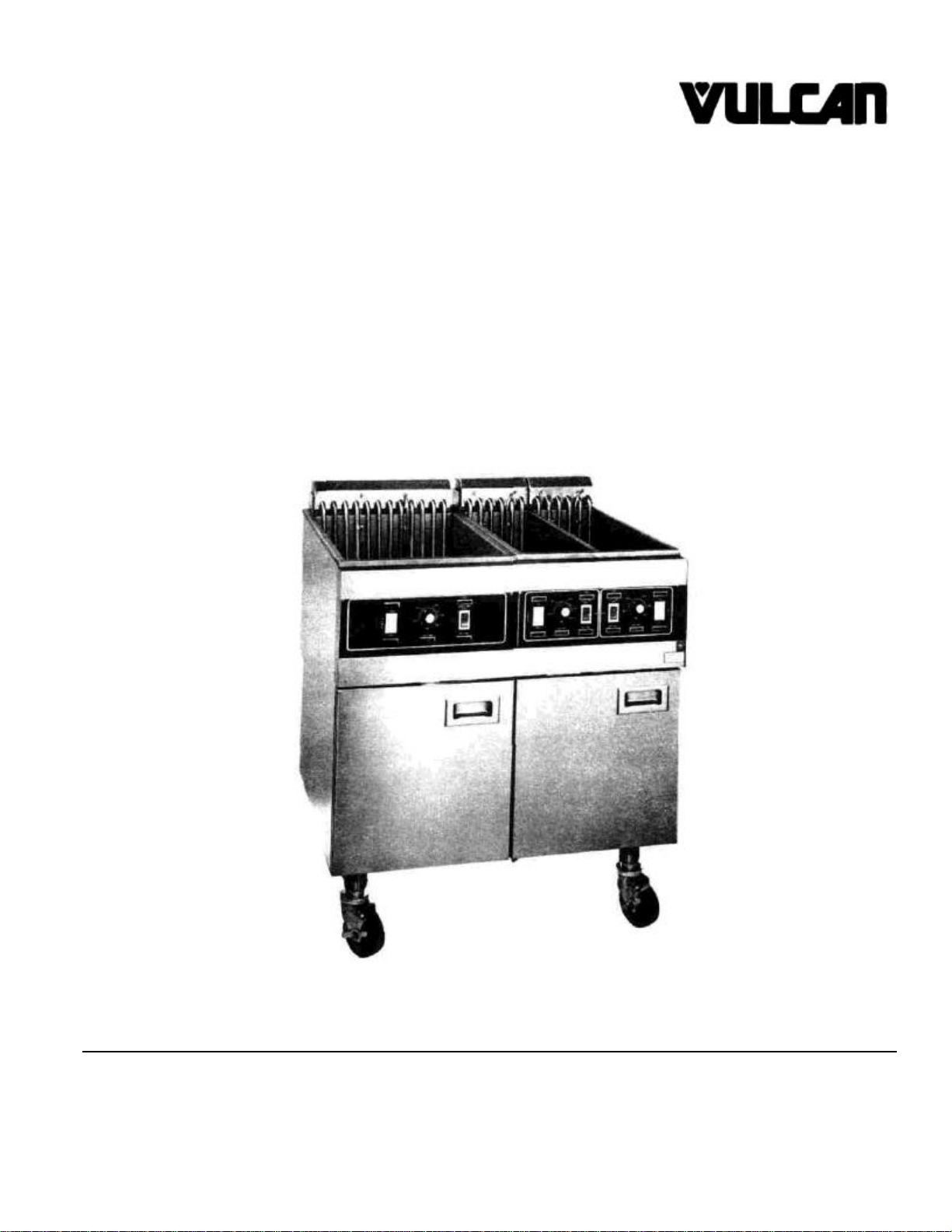
Page 5

MANUAL PART NO.:
114548
-1
FOR MODELS: EEF-1M, 2M, 3M
2SM, 4SM & 6SM
ELECTRIC FRYERS
DESCRIPTION: INSTALLATION, SERVICE
and PARTS MANUAL
REV. BLOCK
REV.# DATE SIG.
1 9/82 DML
1 7/83 HWS
Page 6

EEF FRYER INSTALLATION, SERVICE
AND PARTS MANUAL - INDEX
Your Vulcan fryer is produced with the best possible
workmanship and material. Proper usage and
maintenance will result in many years of satisfactory
The manufacturer suggests that you thoroughly read this
entire manual and carefully follow all of the instructions
provided.
performance.
DESCRIPTION PAGE
DEFINITIONS OF PERSONNEL (Operating, Installation & Parts) and
SHIPPING DAMAGE CLAIM PROCEDURES (Inside Front Cover)
CAUTIONS 1
INDEX 2
UNCRATING 3
SECTION I INSTALLATION
INSTALLATION NOTES 4
SECTION II SERVICE
MELT CYCLE SERVICING 5
CONTROLS 5
CLEANING HEATING ELEMENTS & THERMOSTAT BULB 6
CALIBRATION PROCEDURES 7
HIGH LIMIT TEST & PROCEDURES 7&8
TROUBLE SHOOTING 9& 10
SECTION III PARTS LIST
PARTS LIST & PHOTOS 11-26
REVISION PAGE (INSIDE BACK COVER)
A rating plate is located on the inside fryer door panel
stating the model number, serial number, voltage and
amperage.
Fryer must be installed at least 16 inches away from open
top flame units.
This appliance is to be installed with a six inch clearance
at the sides and rear adjacent to combustible
construction.
2
Page 7

UNCRATING
EEF UNCRATING INSTRUCTIONS
The following procedure should be followed when uncrating all EEF Fryers.
1. Using caution, cut two horizontal and one ver- 5. Using caution, cut two straps and remove two
tical strap. 2x4 wood braces.
2. Lift outer carton from the unit. 6. Remove protective plastic liner from unit.
3. Lift inner crate liner from the unit. 7. Remove packaging material from unit.
4. Remove cardboard box containing component 8. Open cardboard box containing component
parts off the 2x4 wood packaging braces. parts and unwrap parts. Care should be taken
PART DESCRIPTION
BASKET HANGER 1 2 3 1 2 3
QUICK DISCONNECT 1 1 1 1 1 1
RACK SUPPORTS 2 4 6 2 4 6
PROBE TUBES 1 2 3 2 4 6
CLEAN OUT ROD 1 1 1 1 1 1
when checking unit quantities. See chart below
for correct contents of parts.
UNIT QUANTITIES
1M 2M 3M 2SM 4SM 6SM
3
Page 8
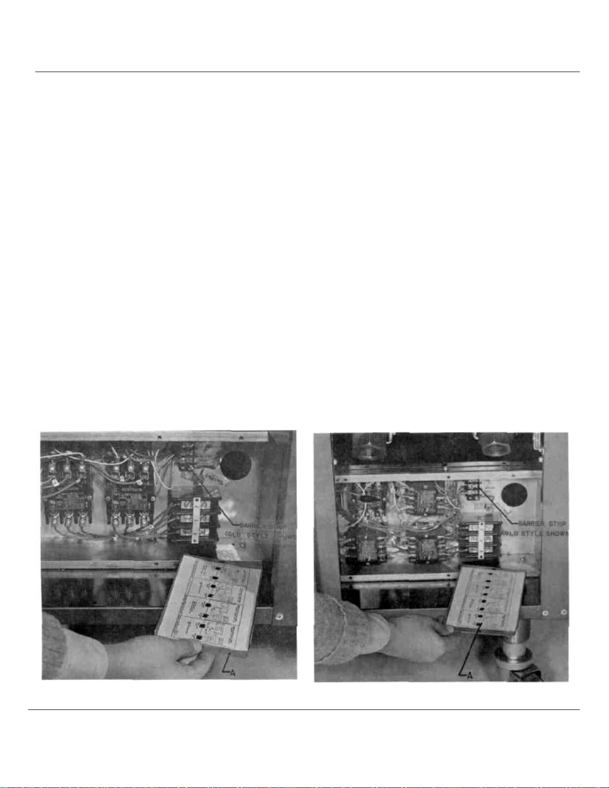
SECTION 1 INSTALLATION
Place fryer as near to its' final position as possible.
Connect 120V 60 Hertz electric supply to fryer
barrier strip. Barrier strip may be connected from
rear of unit. To reach barrier, remove electric cover
plate "A" from unit. After connecting 120V 60 Hertz
electric supply to fryer barrier strip, verify with a
voltmeter that the following condition exists. (SEE
For each 151/2" section a high voltage line capable
of handling 16 KW at the unit's rated voltage (208,
240, 480) is required. If a fan interlock is needed, it
should be connected to 1 and 2 on the terminal
block. 1 and 2 go to a set of dry contacts on the
power switch.
1. Black to white 120V 60 Hertz.
2. Black to ground 120V 60 Hertz.
3. White to ground 0.00V 60 Hertz.
DETAILS A & B)
NOTE: Remove lower back panel from unit and
check to see that harness cable "A" is fastened
securely to the temperature controller box "B". Field
repair of the temperature controller board is not
practical, therefore, when the board malfunctions, it
must be completely replaced. Remove board from
unit by disconnecting cable harness from controller
box and open controller box by removing the (2)
screws that tie into the back of the electric connection
box "C". (See detail "C")
DETAIL "A" DETAIL "B"
4
Page 9
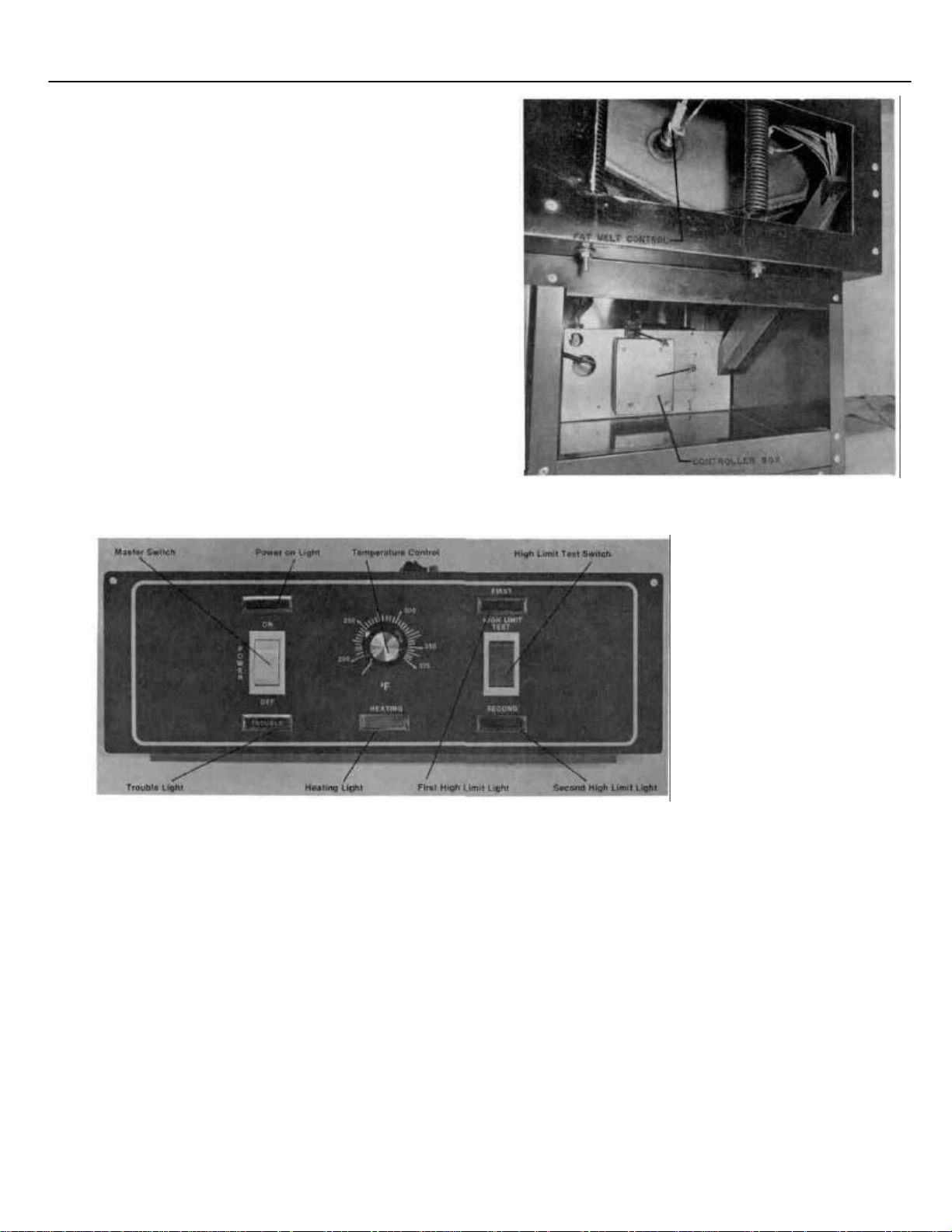
SECTION 2 SERVICE MELT CYCLE SERVICING
CONTROLS
1.
Set the temperature control knob to the frying
temperature and turn on the master switch.
2.
Elements will cycle on for 2 seconds and off for 28
seconds until the shortening melts and a
temperature of 135 degrees F. is obtained, after
which the operating thermostat will take over and
bring the unit to the set temperature. If the fat
melt cycle fails to respond, see item 3 below.
3.
Should the fat melt device require replacement
(See Detail "C"), Remove the back panel from the
rear of the unit, disconnect the wires and unscrew
fat melt control located on the left hand side of
unit. Replace with new fat melt control.
DETAIL C
1.
Master Switch — Controls electric supply to unit.
(Optional - Ventilator interlock)
2.
Power "ON" Light — Light Indicates when electrical supply Is On.
3.
Temperature Control — Maintains frying temperature by controlling
power supply.
4.
Heating Light — When "ON", indicates temperature control is call-
ing for power to elements.
5.
High Limit Test Switch — Bypasses temperature control for testing of high
limit thermostats.
6.
First High Limit Light — When "ON", indicates first high limit thermostat
has shut down unit.
(No reset required:)
7.
Second High Limit Light — When "ON", indicates second high limit ther-
mostat has shut down unit.
(Reset required)
8.
Trouble Light — Indicates unit has been shut down by second high
limit thermostat.
5
DETAIL D
Page 10

CLEANING HEATING ELEMENTS & THERMOSTAT BULB
6
1.
The kettle must be at operating temperature.
2.
Turn Master Switch off.
3.
Raise elements out of hot shortening with a lift
rod and allow shortening to drip off for five
minutes.
CAUTION:
4.
Place cover(s) over kettle(s). To prevent fire and
preserve clean shortening.
5.
Turn operating thermostat to 300 degrees F.
6.
Turn Master Switch on. Do not leave the fryer
unattended. The second high limit will trip out
terminating the burn off cycle.
7.
Turn Master Switch off at termination of burn off
cycle.
8. Heating elements will heat up in excess of 600
degrees F. glowing Red. If any do not glow, call
Service Agency. Some smoking, crackling sound
and flames will occur. This is normal. If excessive flaming occurs, extinguish immediately
to prevent damage to elements and thermostat
bulbs.
9. Allow elements to cool and press reset button on
rear of element head. (See Detail "E")
10. Brush residue from elements and thermostat
bulbs with a stiff nylon bursh. Care should be
taken not to bend or displace temperature con
troller bulbs.
11. Remove cover(s) from kettle(s) and lower
elements into shortening.
12. Proceed with filtering procedures.
DETAIL E
Page 11

CALIBRATION PROCEDURES
7
1. Place the shortening pyrometer and pyrometer holding
fixture, or the shortening digital and digital holding fixture
in the kettle.
2. Turn on the Master Switch and when coming up from
lower temperature, set temperature control knob to frying
temperature.
3. Allow unit to reach temperature (when heating light
goes out) and maintain it (by cycling) for 15 minutes.
HIGH LIMIT TEST
DEFINITION
A test to determine if the protection devices are properly
functioning.
4. Check the reading on the pyrometer or the digital,
when the heating light first comes on. If the reading is not
within five degrees of the temperature control setting, the
following steps should be taken:
A. Loosen the set screws in the temperature control
knob.
B. Rotate the knob and set the knob to read the
same as the pyrometer or the digital readings.
C. Tighten the set screw.
D. Allow the unit to cycle and check the readings.
E. Should for any reason calibration not be obtained
in this manner, call a Service Agency.
HIGH LIMIT TEST & PROCEDURES
1. Turn the Master Switch on and set the temperature
control knob to frying temperature.
2. Heat shortening until the heating light goes out.
3. Depress the top of the high limit test (Red) switch and
hold until first high limit light comes on, then release
switch. (Light will come on at 410 Degrees F.)
4. Depress the bottom of the high limit test switch and
hold until second high limit light comes on, then release
switch. (Light will come on at 435 Degrees F.)
5. Once the unit cools down, press the reset button on the
rear of element head, normal fryer operation will then
automatically be resumed.
THE ABOVE INSTRUCTIONS MAY BE FOUND ON THE
INSIDE OF THE FRYER DOOR.
(SEE DETAIL "F")
Detail "F"
Page 12

HIGH LIMIT TEST AND PROCEDURES
DETAIL G INDICATES THE LOCATING DIMENSIONS OF THE HIGH LIMIT BULB IN RELATIONSHIP TO THE
FRYER ELEMENT.
DETAIL G
8
Page 13

TROUBLE SHOOTING
PROBLEM
FRYER DOES NOT HEAT. A. On-off switch not on. A. Turn on/off switch on.
NO POWER "ON" LIGHT. B. 115v store circuit breaker off B. Reset store circuit breaker.
POWER SWITCH ON, POWER A. Ventilator circuit breaker A. Reset ventilator circuit
POWER LIGHT ON.
VENTILATOR OFF. B. Open wiring in interlock system. B. Call Service Agency.
POWER SWITCH ON, A. High voltage store circuit A. Reset store circuit breaker.
POWER LIGHT ON,
NO HEAT LIGHT
CONTACTORS CAN BE HEARD B. Heating light defective. B. Call Service Agency
CYCLING EVERY 30 SECONDS.
POWER SWITCH ON, A. Temperature control set too low. A. Set temperature control to
POWER LIGHT ON, NO
HEATING LIGHT. B. Fat melt timer inoperative. B. Call Service Agency.
POWER SWITCH ON, A. Shortening temperature above 4 Allow shortening to cool to 390
POWER LIGHT ON,
NO HEATING LIGHT,
TROUBLE LIGHT AND B. Second high limit operative. B. Call Service Agency.
SECOND HIGH LIMIT
LIGHT ON.
MELT CYCLE DOES NOT A. Melt cycle thermostat is still A. Allow kettle to cool.
FUNCTION (UNIT GOES
TO FULL HEAT WHEN
TURNED ON).
WHEN MELTING SOLID A. Heating element rack not moved A. Remove rack, allow system to
SHORTENING, FULL POWER
APPLIED BEFORE ELEMENTS B. Solid fat not properly located B. Insure block is centered over
COVERED WITH LIQUEFIED
SHORTENING.
CAUSE
C. Control voltage plug not plugged C. Plug in all power supply cords
in wall.
D. Control circuit not connected D. Call Service Agency.
to power inside fryer.
E. On-off switch defective. E. Call Service Agency.
tripped.
C. Defective power switch. C. Call Service Agency.
breaker tripped.
(One for each I51/2" fryer section)
(Oil temperature increasing
with out heating light indicator).
C. Solid State temperature control C. Call Service Agency
inoperative.
435 degrees, second high limit
operative.
hot from a previous change of
hot shortening.
B. Melt thermostat defective. B. Call Service Agency.
C. Melt timer defective. C. Call Service Agency.
prior to adding solid shortening.
on heating elements.
C. Fat melt thermostat defective. C. Call Service Agency.
REMEDY
and insure twist locks are
engaged.
breaker.
normal cooking temperature.
degrees and push second high
limit reset button.
To force cool, pack solid short
ening around fat melt
thermostat. (Rear wall of fry tank),
cool and initiate fat melt.
element coils and pushed full to
back of fry tank.
9
Page 14

TROUBLE SHOOTING
PROBLEM CAUSE REMEDY
EXCESSIVE TIME TO MELT A. Melt cycle thermostat out of A. Call Service Agency.
SHORTENING (MORE THAN
45 MINUTES). B. Melt cycle timer incorrect, B. Call Service Agency to
UNIT NEVER COMES OUT A. Defective fat melt thermostat. A. Call Service Agency.
OF FAT MELT.
FRYER COMES ON, NO FAT A. Stuck contactor in temperature A. Turn off and tag fryer for non-use
MELT CYCLE. FRYER HEATS
UNTIL 2ND HIGH LIMIT TRIPS
(RUNAWAY).
FRYER GOES THROUGH FAT A. Defective temperature control A. Call Service Agency.
MELT, THE FULL HEAT RUNS
UNTIL 1ST OR 2ND HIGH
LIMIT TRIPS (RUNAWAY).
FRYER SHUTS DOWN ON A. Fryer out of calibration. A. Recalibrate, see calibration
HIGH LIMIT AT TEMPER
ATURE SETTINGS BELOW B. Defective high limit (s). B. Call Service Agency.
375 DEGREES F.
THERMOSTAT OUT OF
CALIBRATION BY LESS
THAN 25 DEGREES.
THERMOSTAT OUT OF A. Solid State Control Board A. Call Service Agency
CALIBRATION BY MORE
THAN 25 DEGREES. B. Thermistor probe bent. B. Call Service Agency.
ONE OR MORE OF THE A. Defective element(s). A. Call Service Agency.
HEATING ELEMENTS DO B. Defective contactor section. B. Call Service Agency.
NOT GET RED DURING
BURN-OFF
ELEMENTS WILL NOT A. Improper clamping of high A. Call Service Agency.
BURN OFF.
ELEMENTS GET BRIGHT RED A. Second high limit malfunction. A. Call Service
DURING BURN OFF. B. Improper clamping or position B. Call Service Agency.
FRYER FUNCTIONING A. Defective light. A. Call Service Agency.
NORMALLY, HOWEVER: B. Defective wiring. B. Call Service Agency.
1. ON LIGHT NOT ON.
2. HEATING LIGHT NOT ON WHEN
HEATING.
3. 1ST HIGH LIMIT LIGHT NOT ON
AFTER 1ST HIGH LIMIT TRIP.
4. 2ND HIGH LIMIT OR TROUBLE
LIGHT.
NOT ON AFTER 2ND HIGH LIMIT TRIP.
calibration.
should be 2 seconds 'on' 28
seconds 'off.
C. Defective heating elements. C. Call Service Agency.
D. Heating element power/supply D. Call Service Agency.
problem.
control system.
board.
defective.
(Touching element)
limit or thermostat bulbs.
B. Thermostat bulb bent. B. Call Service Agency.
ing of second high limit.
replace timer.
until Service Agency has repaired.
instructions
Recalibrate (See calibration
instructions)
Page 15

SECTION 3 PARTS LIST
EEF FRYER
REPLACEMENT PARTS LIST
&
PHOTOS
REPLACEMENT PARTS ORDERING
The following information must accompany a replacement parts order or it cannot be filled.
A. Model and Style or Serial Number.
B. Voltage and Phase.
C. Appliance Finish, Permafinish, Stainless Steel,
Etc. (If applicable to part to be replaced.)
This information can be found on the instruction plate on the unit Parts
may be ordered from your dealer, service agency, or the factory Orders to
the factory should be addressed as shown below.
VULCAN-HART CORP. 3600
NORTH POINT BLVD.
BALTIMORE, MD 21222
11
Page 16

PARTS LIST
ITEM
NO.
1 114339-G1 MAIN TOP ASSEMBLY (NS) 1 - - 1 - 2
3
4
5
6
7
8
9
10
10A
NS= NOT SHOWN BY PHOTOGRAPH
PART
NUMBER
114184-G1
114192-G1
114206-1
114159-G2
114194-2
114043-2
114123-G1
111686-2
114210-1
114210-2
DESCRIPTION
MAIN TOP ASSEMBLY (NS)
MAIN TOP ASSEMBLY
BASKET HANGER
PROBE TUBE
SINGLE CONTROL PANEL
SPLIT CONTROL PANEL MYLAR
DOOR PANEL ASSEMBLY
HANGER BUTTONS
CASTER WITH BRAKES
CASTER WITHOUT BRAKES
EEF EEF EEF EEF EEF EFF
-1M -2M -3M -2SM -4SM 6-SM
-
1 -
- - 1 - - 1
1 2 3 1 2 3
1 2 3 2 4 6
1 2 3 -
- - 1 2 3 1 2 3
2 4 6 2 4 6
2 2 2 2 2 2
2 2 2 2 2 2
-
1 2 3
1 -
-
-
12
Page 17

PARTS LIST
ITEM
NO
1
2
3
11
12
13
14
10
10A
15
16
17
13 NS=NOT SHOWN BY PHOTOGRAPH
PART
NUMBER
114339-G1
114184-G1
114192-G1
114225-1
114163-1
114199-1
114345-1
114210-1
114210-2
114146-1
114344-1
114175-G1
DESCRIPTION -1M -2M -3M -2SM -4SM -6SM
MAIN TOP ASSEMBLY (NS) 1
MAIN TOP ASSEMBLY (NS)
MAIN TOP ASSEMBLY
BODY BACK 1 - - 1
BODY BACK (NS)
BODY BACK (NS)
REAR DOOR 1 2 3 1 2 3
CASTER WITH BRAKES 2 2 2 2 2 2
CASTER WITHOUT BRAKES 2 2 2 2 2 2
RESET BUTTON (HIGH LIMIT) 1 2 3 2 4 6
REAR CLOSURE 1 2 3 1 2 3
ELEMENT HEAD SUPPORT ASSEMBLY 2 4 6 2 4 6
EEF EEF EEF EEF EEF EEF
- -
-
1
-
-
-
1
-
-
1
1 -
1
-
-
- 1
- -
1
-
-
-
-
1
-
-
1
Page 18

PARTS LIST
ITEM PART
NO.
NUMBER DESCRIPTION -1M -2M -3M -2SM
6 114194-2 MYLAR CONTROL PANEL COVER (SINGLE VAT) 1 2 3
18 114042-G1 CONTROL PANEL ASSEMBLY (SINGLE VAT) 1 2 3
19 111496-E4 SIGNAL LIGHT (RED) 3 6 9
20 111496-B1 ON-OFF SWITCH 1 2 3
21 111496-E6 TROUBLE LIGHT 1 2 3
22 111496-E3 HEAT LIGHT (AMBER) 1 2 3
23 114254-1 POTENTIOMETER KNOB 1 2 3
24 111496-B3 TEST SWITCH (RED) 1 2 3
25 114147-1 POTENTIOMETER (NS) 1 2 3
NS= NOT SHOWN BY PHOTOGRAPH
EEF EEF
EEF EEF EEF EEF
-4SM -6SM
-
-
-
-
-
-
-
-
-
-
-
-
-
-
-
-
-
-
-
-
-
-
-
-
-
-
-
14
Page 19

PARTS LIST
ITEM PART EEF EEF EEF EEF EEF EEF
NO. NUMBER DESCRIPTION -1M -2M -3M -2SM -4SM -6SM
7 114043-2 MYLAR CONTROL PANEL COVER (SPLIT) - - - 1 2 3
-
18A 114042-G2 CONTROL PANEL ASSEMBLY (SPLIT)
19 111496-E4 SINGAL LIGHT (RED) - - - 6 12 18
20 111496-B1 ON-OFF SWITCH - - - 2 4 6
21 111496-E6 TROUBLE LIGHT
22 111496-E3 HEAT LIGHT (AMBER)
23 114254-1 POTENTIOMETER KNOB
24 111496-B3 TEST SWITCH (RED) - - - 2 4 6
25 114147-1 POTENTIOMETER (NS)
NS = NOT SHOWN BY PHOTOGRAPH
15
-
-
-
-
-
-
-
-
-
- 1 2 3
- 2 4 6
- 2 4 6
-
2 4 6
- 2 4 6
Page 20

PARTS LIST
ITEM PART
NO.
NUMBER DESCRIPTION -1M -2M
40 114088-Q1 TANK ASSEMBLY (SPLIT) (NS)
42 114164-1 POWER SUPPLY CABINET -
43 114165-1 CONTACTOR COVER - - - 1 2 3
44 114166-1 TERMINAL BLOCK COVER - - - 1 2 3
45 108834-1 DOOR MAGNET - - - 1 2 3
46 112779-1 DOOR HINGE (BOTTOM) - -
47 112779-2 DOOR HINGE (TOP) - - - 1 2 3
48 113797-1 DISCONNECT CAUTION DECAL - - - 1 2 3
50 106715-1 TURN DISCONNECT DECAL - - - 1 2 3
51 114212-2 1" BALL VALVE, LEFT HAND - -
52 114212-2 1" BALL VALVE, RIGHT HAND
53 114098-2 DRAIN PIPE(NS) -
54 114346-1 LOWER FRONT CLOSURE -
55 114348-1 TOP FRONT CLOSURE - - - 1 2 3
NS= NOT SHOWN BY PHOTOGRAPH
EEF EEF EEF EEF EEF EEF
-3M -2SM -4SM -6SM
-
-
-
- 1 2 3
-
- 1 2 3
-
-
-
- 1 2 3
-
- 1 1 1
-
- 1 2 3
1 2 3
1 2 3
16
Page 21

PARTS LIST
ITEM PART
NO.
NUMBER DESCRIPTION -1M -2M -3M
77 114826-1 BRKT.HI-LIMIT 1 2 3 2 4 6 4 2
26 114224-G1 FRY TANK ASSEMBLY (SINGLE) 1 2 3
9 111686-2 HANGER BUTTON 2 4 6 -
5 114159-G2 PROBE TUBE 1 2 3 -
4 114206-1 BASKET HANGER 1 2 3
27 114309-G1 ELEMENT HEAD ASSEMBLY 1 2 3
28 114214-2 BSK'T SUPPORT RACKS (SINGLE) 1 2 3 - - -
29 114177-1 ELEMENT CLAMP BOTTOM 2 4 6
30 114177-2 ELEMENT CLAMP TOP 4 8 12
31 114142-1 THERMOSTAT PROBE 1 2 3
32 114146-2 SECOND HIGH LIMIT 1 2 3
33 114237-1 DOUBLE ELEMENT CLAMP ANGLE 1 2 3 -
34 111830-1 HIGH LIMIT BULB CLAMP 4 8 12 -
35 106666-42 PROBE CLAMP 4 8 12
36 114027-1 HEATING ELEMENT 208V 'SELECT' 6 12 18
36A
114027-2 HEATING ELEMENT 240V (NS) 'PROPER' 6 12 18
36 B
NS = NOT SHOWN BY PHOTOGRAPH
114027-3 HEATING ELEMENT 480V (NS) 'VOLTAGE' 6 12 18
37 3.0316-1 TUBE CLAMP 3 6 12
38 114143-1 FAT MELT THERMOSTAT 1 2 3
39 114143-2 FIRST HIGH LIMIT 1 2 3
EEF
EEF EEF
EEF EEF EEF EEF EEF
-2SM -4SM -6SM -4SFM -2FM
-
- -
-
-
-
-
-
-
-
-
- -
-
- -
-
- -
-
- -
-
- -
-
-
-
-
-
-
-
-
-
-
-
-
-
-
-
-
-
-
-
-
-
-
-
-
-
17
Page 22

PARTS LIST
ITEM
PART
NO.
NUMBER DESCRIPTION -1M -2M -3M -2SM
77 114826-1 BRKT. HI-LIMIT 1 2 3 2 4 6 4 2
40 114088-G1 FRY TANK ASSEMBLY (SPLIT))(NS)
9 111686-2 HANGER BUTTON - - - 2 4 6 - -
5 114159-G2 PROBE TUBE - - - 2 4 6 - -
4 114206-1 BASKET HANGER - - - 1 2 3 - -
27 114306-G1 ELEMENT HEAD ASSEMBLY - - - 2 4 6 - -
28 114214-1 BASKET SUPPORT RACKS (SPLIT) - - - 2 4 6 - -
29 114177-1 ELEMENT CLAMP BOTTOM
30 114177-2 ELEMENT CLAMP TOP
31 114142-1 THERMOSTAT PROBE - - - 2 4 6 - -
32 114146-2 SECOND HIGH LIMIT
34 111830-1 HIGH LIMIT BULB CLAMP
35 106666-42 PROBE CLAMP - - - 8 16 24 - -
36 114027-1 HEATING ELEMENT 208V 'SELECT' - - - 6 12 18 - -
36A
114027-2 HEAT. ELEMENT 240V (NS) 'PROPER' - - - 6 12 18 - -
36B
114027-3 HEAT. ELEMENT 480V (NS) 'VOLTAGE' - - - 6 12 18 - -
37 3.0316-1 TUBE CLAMP - - - 6 12 18 - -
38 114143-1 FAT MELT THERMOSTAT - - - 2 4 6 - -
39 114143-2 FIRST HIGH LIMIT - - - 2 4 6 - -
41 114176-1 ELEMENT CLAMP ANGLE
NS = NOT SHOWN BY PHOTOGRAPH
EEF EEF
-
-
-
-
-
-
EEF EEF EEF
-4SM -6SM -4SFM -2FM
- - 1 2 3 - -
- - 2 4 6 - -
- - 4 8 12 - -
- - 2 4 6 - -
- - 8 16 24 - -
- - 2 4 6 - -
EEF EEF EEF
18
Page 23

PARTS LIST
ITEM PART
NO. NUMBER DESCRIPTION -1M -2M -3M -2SM -4SM 6-SM -4SFM -2FM
56 1110472-8 TERMINAL BLOCK (OLD STYLE SHOWN) 1 2 3
57 114208-1 TERMINAL BARRIER STRIP (OLD STYLE SHOWN) 1 2 3 - - - - -
62 111497-C6 CONTACTOR 2 POLE, 30A (OLD STYLE SHOWN) 2 4 6 - - 59 3.1500 GROUND LUG 1 2 3 - - - - 60 110711-1 GROUND LABEL 1 2 3 - - - - 44 114166-1 TERMINAL BLOCK COVER 1 2 3 - - - - 61 114470-1 DECAL FOR WIRING PLANS 1 1 1 - - -
EEF EEF EEF EEF EEF EFF EEF EEF
-
- - - -
-
-
-
-
19
Page 24

PARTS LIST
ITEM PART
NO NUMBER DESCRIPTION
58 110472-8 TERMINAL BLOCK (OLD STYLE SHOWN) - - - 1 2 3 - -
57 114208-1 TERMINAL BARRIER STRIP (OLD STYLE SHOWN)
56 111497-C1 CONTACTOR 3 POLE 30A (OLD STYLE SHOWN) - - - 1 2 3 - 59 3.1500 GROUND LUG - - - 1 2 3 - 60 110711-1 GROUND LABEL - - - 1 2 3 - 44 114166-1 TERMINAL BLOCK COVER - - - 1 2 3 - 61 114470-1 DECAL FOR WIRING PLANS - - - 1 2 3 - -
EEF
-1M
-
EEF EEF EEF EEF EEF EEF EEF
-2M -3M -2SM -4SM -6SM -4SFM -2FM
-
- 1 2 3 - -
20
Page 25

PARTS LIST
ITEM PART
NO. NUMBER DESCRIPTION -1M -2M -3M -2SM -4SM -6SM
26 114224-G1 TANK ASSEMBLY (SINGLE) (NS) 1 2 3
42 114164-1 POWER SUPPLY CABINET 1 2 3 - - 43 114165-1 CONTACTOR COVER 1 2 3 - - 44 114166-1 TERMINAL BLOCK COVER 1 2 3 - - 45 108834-1 DOOR MAGNET 1 2 3 - - 46 112779-1 DOOR HINGE (BOTTOM) 1 2 3 - - 47 112779-2 DOOR HINGE (TOP) 1 2 3 - - 48 113797-1 DISCONNECT CAUTION DECAL 1 2 3 - - 50 106715-1 TURN DISCONNECT DECAL 1 2 3 - - 51 114212-1 1 " BALL VALVE 1 2 3 - - 53 114098-2 DRAIN PIPE (NS) 1 1 1 - - 54 114346-1 LOWER FRONT CLOSURE 1 2 3 - - 55 114348-1 TOP FRONT CLOSURE 1 2 3 - - -
NS = NOT SHOWN BY PHOTOGRAPH
EEF EEF EEF EEF EEF EEF
-
- -
21
Page 26

PARTS LIST
ITEM PART
NO. NUMBER DESCRIPTION -1M -2M
26 114224-G1 TANK ASSEMBLY (SINGLE) 1 2 3 - - 62 106363-1 ELEMENT HEAD SPRING 2 4 6 - - 63 10795-2 EYE BOLT 2 4 6 - - -
64 114143-1
65 114143-2
66 114195-1 WIRE CHANNEL 1 2 3 - - -
FAT MELT THERMOSTAT – 135
DEGREES F.
FIRST HIGH LIMIT - 410
DEGREES F.
EEF EEF
1 2 3 - - 1 2 3 - - -
EEF
-3M -2SM -4SM -6SM
EEF EEF
EEF
22
Page 27

PARTS LIST
ITEM
NO.
40 114088-G1 TANK ASSEMBLY SPLIT)
62 106363-1 ELEMENT HEAD SPRING
63 10795-2 EYE BOLT - - - 2 4 6 - -
64 414143-1
65 114143-2
66 114195-1 WIRE CHANNEL
PART
NUMBER
DESCRIPTION
FAT MELT THERMOSTAT - 135
DEGREES F.
FIRST HIGH LIMIT - 410
DEGREES F.
EEF
EEF
-1M
-2M
-
- - - 2 4 6 - -
- - - 2 4 6 - -
-
EEF
EEF
-3M
-2SM
- - 2 4 6 - -
- - 1 2 3 - -
EEF
-4SM
1 2 3
EEF
-6SM
EEF
-4SFM
EEF
-2FM
23
Page 28

PARTS LIST
ITEM PART
NO NUMBER DESCRIPTION -1M -2M -3M -2SM
8 114123-G1 FRYER DOOR PANEL ASSEMBLY 1 2 3 1 2 3
67 113810-2 ELECTRIC RATING PLATE 1 1 1 1 1 1 68 113831-1 IMPORTANT PLATE 1 1 1 1 1 1 - 69 114095-1 HIGH LIMIT TEST DECAL 1 1 1 1 1 1 - 70 114281-1 OPERATION INSTRUCTIONS 1 1 1 1 1 1 - 71 114245-1 DRAIN PIPE HOOK (TOP) 1 1 1 1 1 1 - 72 114246-1 DRAIN PIPE HOOK (BOTTOM) 1 1 1 1 1 1 - 53 114094-2 DRAIN PIPE 1 1 1 1 1 1 - -
EEF EEF EEF EEF EEF EEF
-4SM -6SM -4SFM -2FM
EEF EEF
-
-
-
24
Page 29

PARTS LIST
ITEM PART
NO. NUMBER DESCRIPTION -1M -2M -3M -2SM -4SM 6-SM -4SFM -2FM
73 114214-2 BASKET RACK SUPPORT (SINGLE) 1 2 3 74 114214-1 BASKET RACK SUPPORT (SPLIT) -
EEF EEF EEF EEF EEF EFF EEF EEF
- - - -
- - 2 4 6 - -
25
Page 30

PARTS LIST
ITEM PART
NO NUMBER DESCRIPTION -1M -2M
75 114197-G1 FRY TANK COVER ASSEMBLY 1 2 3 1 2 3
76 107023-1 FRY TANK COVER HANDLE 1 2 3 1 2 3
EEF EEF EEF EEF EEF EEF
-3M -2SM -4SM -6SM -4SFM -2FM
EEF EEF
-
-
-
-
26
 Loading...