

Page 1
SERVICE MANUAL
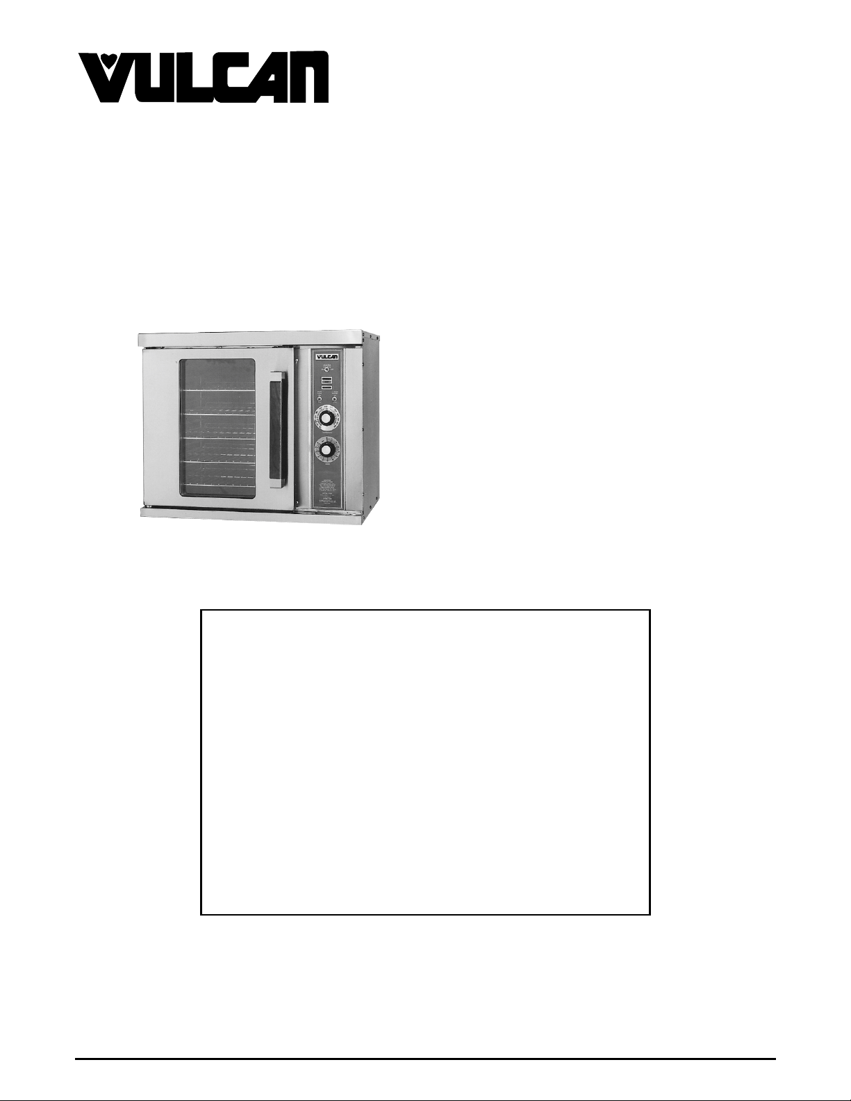
HALF-SIZE
CONVECTION OVENS
ELECTRIC AND GAS
MODEL ML
ELECTRIC
GCO2D Shown
This Manual is prepared for the use of train ed Vulcan Service
Technicians and should not be used by those not properly
qualif ied. If you have att ended a Vu lcan Service School for this
product, you may be qualified to perform all the procedures
described in this man ual.
Thi s manu al i s no t i nten ded to be al l en comp assi ng . I f you have
not attende d a Vulcan Servic e School f or this produc t, you should
read, in its entirety, the repair procedure you wish to perform to
determine if you have the necessary tools, instruments and skills
required to perform the procedure. Procedures for which you do
not have th e necessary t oo ls, in strument s and skills should be
performed b y a trained Vu lcan Service Technician .
ECO2D 114570
ECO2C 114572
GAS
GCO2D 114569
GCO2C 114571
- NOTICE -
Reproduction or other use of this Manual, without the express
written consent of Vulcan-Hart, is prohibited.
A product of VULCAN-HART LOUISVILLE , KY 40201-0696
Form 24575 ( 12/96)
Page 2

HALF-SIZE CONVECTION OVENS
TABLE OF CONTENTS
GENERAL............................................................................. 3
Introduction ....................................................................... 3
Specifications ..................................................................... 3
Gas Ovens................................................................ 3
Electric Ovens ............................................................. 3
Tools............................................................................ 3
REMOVAL AND REPLACEMENT OF PARTS ................................................. 4
Covers and Panels ................................................................. 4
Control Panel Components ........................................................... 5
Blower And/or Blower Motor........................................................... 6
Oven Door........................................................................ 7
Door Switch....................................................................... 8
Heat Exchanger (Gas Ovens) ......................................................... 8
Burner (Gas Ovens)................................................................. 9
Gas Valve (Gas Ovens).............................................................. 9
Heating Elements (Electric Ovens) .................................................... 10
SERVICE PROCEDURES AND ADJUSTMENTS .............................................. 11
Temperat ure Probe Test (Al l Models) .................................................. 11
Verification of Spark at Spark Probe ................................................... 11
Gas Pressure Adjustment ........................................................... 12
Spark Ignition Control Test .......................................................... 12
Electronic Control ................................................................. 13
Solid State Control Test............................................................. 14
Solid State Control Calibration........................................................ 14
Door Switch Adjustment............................................................. 15
Door Reversal .................................................................... 16
Door Adjustment .................................................................. 17
Blower Adjustment................................................................. 17
Element Test..................................................................... 17
ELECTRICAL OPERATION .............................................................. 18
Component Func tion ............................................................... 18
Component Locat ion ............................................................... 19
Sequence of O per ation ............................................................. 20
Ignition Module ............................................................ 20
Gas Oven................................................................ 20
Electric Oven ............................................................. 23
Schematics Gas Ovens............................................................. 26
GCO2D ................................................................. 26
GCO2C ................................................................. 27
Wiring Diagram - Gas Ovens......................................................... 28
GCO2D ................................................................. 28
GCO2C ................................................................. 30
Schematic-Electric Ovens ........................................................... 32
ECO2D ................................................................. 32
ECO2C ................................................................. 33
Wiring Diagram Electric Ovens ....................................................... 34
ECO2D ................................................................. 34
ECO2C ................................................................. 36
TROUBLESHOOTING .................................................................. 38
Electric Ovens.................................................................... 38
Gas Ovens ...................................................................... 39
© VULCAN 1996
2
Page 3
HALF-SIZE CONVECTION OVENS - GENERAL
GENERAL
INTRODUCTION
General
This manual will cover half-s ize ele ctric and gas convection ovens that use either a solid state control or an electronic
control.
Procedures in this manual are applicable t o both gas and electric ovens unless specified.
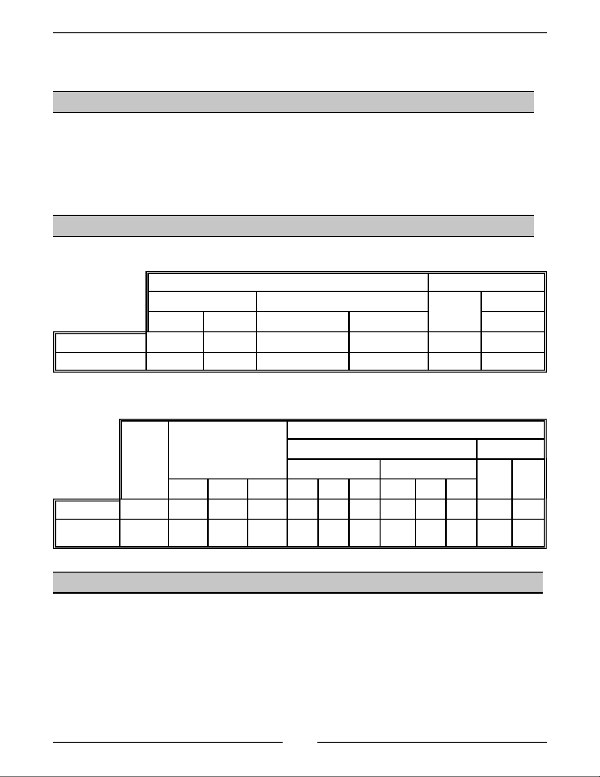
SPECIFICATIONS
GAS OVENS
GAS DATA ELECTRICAL DATA
INPUT BTU/HR MANIFOLD PRESSURE LOAD
Natural Propane Natural Propane 120V
Single Oven 2500 2500 3.5" W.C. 10"W.C. 950 8
Stacked Oven 5000 5000 3.5" W.C 10"W.C. 1900 16
ELECTRIC OVENS
NOMINAL AMPS PER LINE WIRE
3-PHASE LOADING
TOTAL
KW
Single O ven 5.5 2.5 0 3.0 22.9 10.4 12.5 19.9 9.0 10.9 26.5 23.0
Stacked
Ovens
11.0 5.0 0 6.0 45.8 20.8 25.0 39.7 18.0 21.7 52.9 45.9
(KW PER PHASE)
208V 240V 208V 240V
L1-L2 L2-L3 L1-L3 L1 L2 L3 L1 L2 L3
3 PHASE 1 PHASE
(Watts)
AMP/LINE
TOOLS
• Standard set of hand tools
• VOM with AC c ur r ent tester (Any VO M wi th a sensitivity of at least 20, 000 ohms per volt can be used.)
• Temperat ure tester
• Manometer (Gas Ov ens)
3
Page 4
HALF-SIZE CONVECTION OVENS - REMOVAL AND REPLACEMENT OF PARTS
REMOVAL AND REPLACEMENT OF PARTS
COVERS AND PANELS
WARNING:
POWER TO THE MACHINE AT THE MAIN CIRCUIT
BOX. PLACE A TAG ON THE CIRCUIT BOX
INDICATI NG THE CIRCUIT IS BEING SE RV ICED.
WARNING:
SERVICING THE UNIT. (When appl icable)
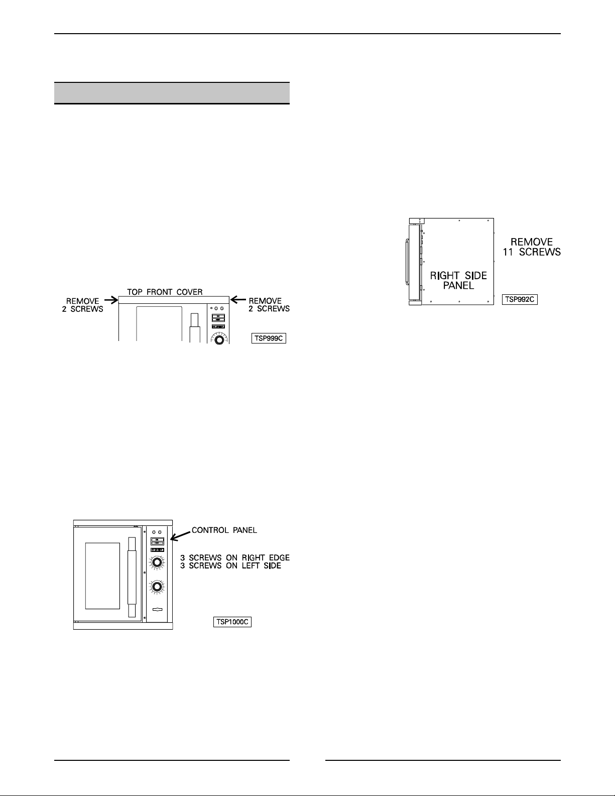
Top Front Cover
1. The t op f ront cover is secured with f our screws,
two on each side of cover. Remove these screws
then pull c over off uni t.
2. Reverse the procedure to install.
DISCONNECT THE ELECTRICAL
SHUT OFF THE GAS BEFORE
Right Side Panel
1. Remove the three screws which secure the right
side of the c ontrol panel.
2. Loosen the two screws on the right side of the top
front c over.
3. Remove the remaining eight screws securing the
right side panel.
4. Pul l the right side panel out at t he bottom then
down to remove.
5. Reverse the procedure to install.
Control Panel
1. On gas models, remove the handle from the
manual gas valve.
2. Remove the three screws from the left front and
loosen the three screws on the ri ght side of the
control panel.
3. Pul l the panel away f r om the oven.
4. Unplug the lead wires to the control panel
components and disconnect the temperature
probe leads.
5. Reverse the procedure to install.
4
Page 5
HALF-SIZE CONVECTION OVENS - REMOVAL AND REPLACEMENT OF PARTS
CONTROL PANEL
COMPONENTS
Removable Components
Listed on the illustration.
Procedure
WARNING
1. Remove the control panel as outlined under
: UNPLUG UNIT BEFORE SERVICING.
"COVERS AND PANELS".
2. Disconnect the wire leads at the component to be
replaced.
3. Rem ove the component.
4. Reverse the procedure to install the new
component, then check oven for proper
operation.
5
Page 6
HALF-SIZE CONVECTION OVENS - REMOVAL AND REPLACEMENT OF PARTS
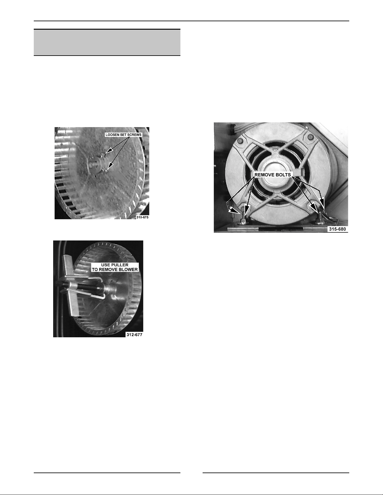
BLOWER AND/OR BLOWER
MOTOR
WARNING
1. Rem ove racks and the r ight rack support.
2. Rem ove baffle panel by lifting up and out.
3. For gas ovens only, remove the heat exchanger
: UNPLUG UNIT BEFORE SERVICING.
as outlined under “HEAT EXCHANGER”.
8. Disconnect the wire leads to the motor.
A. P1 (purpl e) to wire# 11
B. Orange (Low speed) to wire# 12
C. Blue (high speed) to wire# 13
D. Red wires connected together.
9. Rem ove the bolt s that secure the motor to the
motor mounting plate and remove the motor from
the ov en.
4. Loosen set screws on blower hub.
5. Remove blower from motor shaft. You may have
to use a bearing puller.
6. If the blower only is to be replaced, reverse
procedure to install and check blower to be
parallel with the motor mounting plate as outlined
under "BLOW ER A DJUST MENT " i n "SERV ICE
PROCEDURES AND ADJUSTMENTS”. If the
motor is to be replaced, c ontinue to step 7.
10. Place new motor in position on the motor
mounti ng plat e and rout e the wir ing t hrough t he
gromm et in the component panel.
11. Install mounting pads and bolts. DO NOT tighten
mounti ng bolts.
12. Slide the blower onto motor shaft until hub is
flush wit h end of shaft and tighten set screws.
13. Adjust m otor position u nti l blower is parall el to
oven cavity wall with a spacing of ¼" as outlined
under "BLOWER ADJUSTMENT " i n "S ERVI CE
PROCEDURES AND ADJUSTMENTS".
14. Install baffle panel, rack guides and racks.
7. Rem ove the right side panel.
6
Page 7
HALF-SIZE CONVECTION OVENS - REMOVAL AND REPLACEMENT OF PARTS
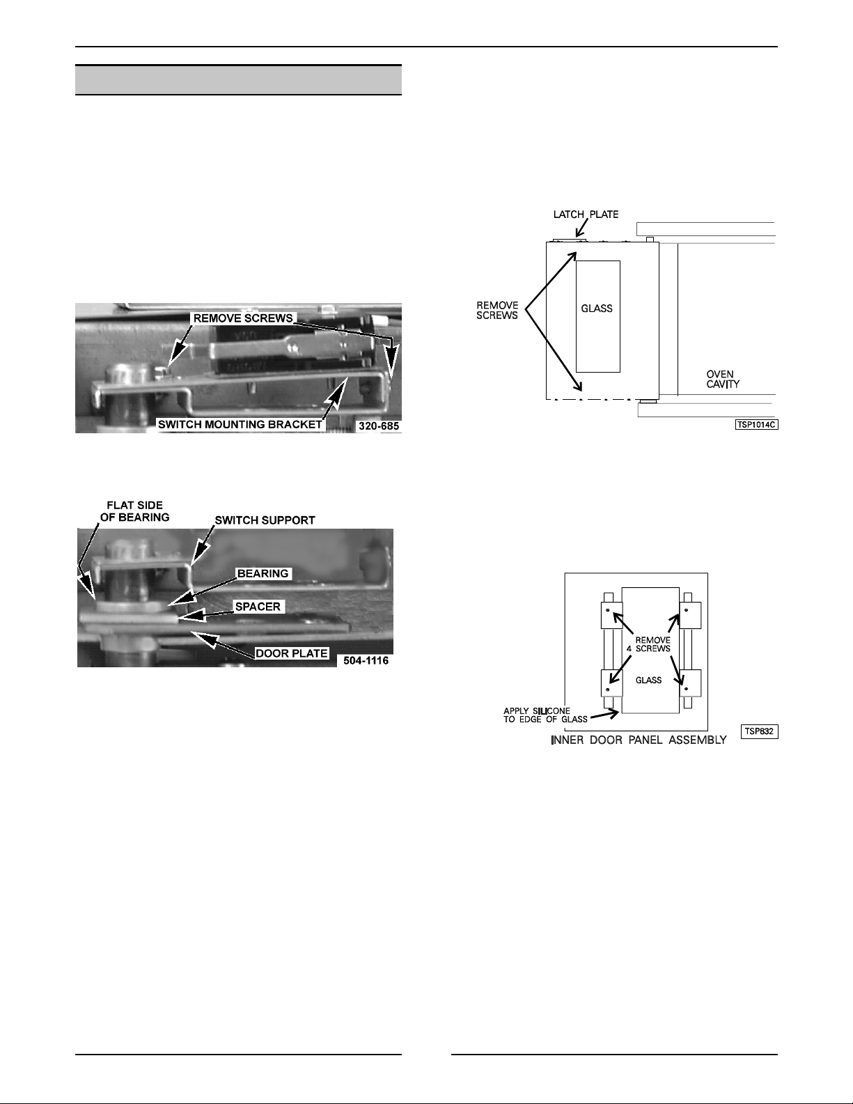
OVEN DOOR
Removal
WARNING:
1. Remove the top front cover as outlined under
"COVERS AND PANELS".
2. Remove the door switch lever from the door
shaft.
3. Rem ove the door switc h br ac k et.
4. Whil e supporti ng the door, rem ove the beari n g,
door plate and spacer.
UNPLUG UNIT BEFORE SERVICING.
Disassembly
1. Open t he door .
2. Rem ove the door handle and latch plate.
3. Rem ov e t he screws which secure the i nner and
outer door panels to the door frame.
4. Rem ove the inner and outer door panel.
5. Remove the four screws and lift the window
assembly out.
5. Lift the door from the lower bearing.
6. Reverse procedure to i nstall door assembly and
check for proper adjustment as outli ned under
"DOOR ADJUST MENT" and "DOOR S WITCH
ADJUSTMENT" in "SERVICE PROCEDURES
AND ADJUSTMENTS".
NOTE:
the window and the door panel.
6. Reverse the procedure to install the new window
and adjust the door as outlined under “DOOR
ADJUSTMENT”.
Use high temperature silicone between
7
Page 8
WARNING:
HALF-SIZE CONVECTION OVENS - REMOVAL AND REPLACEMENT OF PARTS
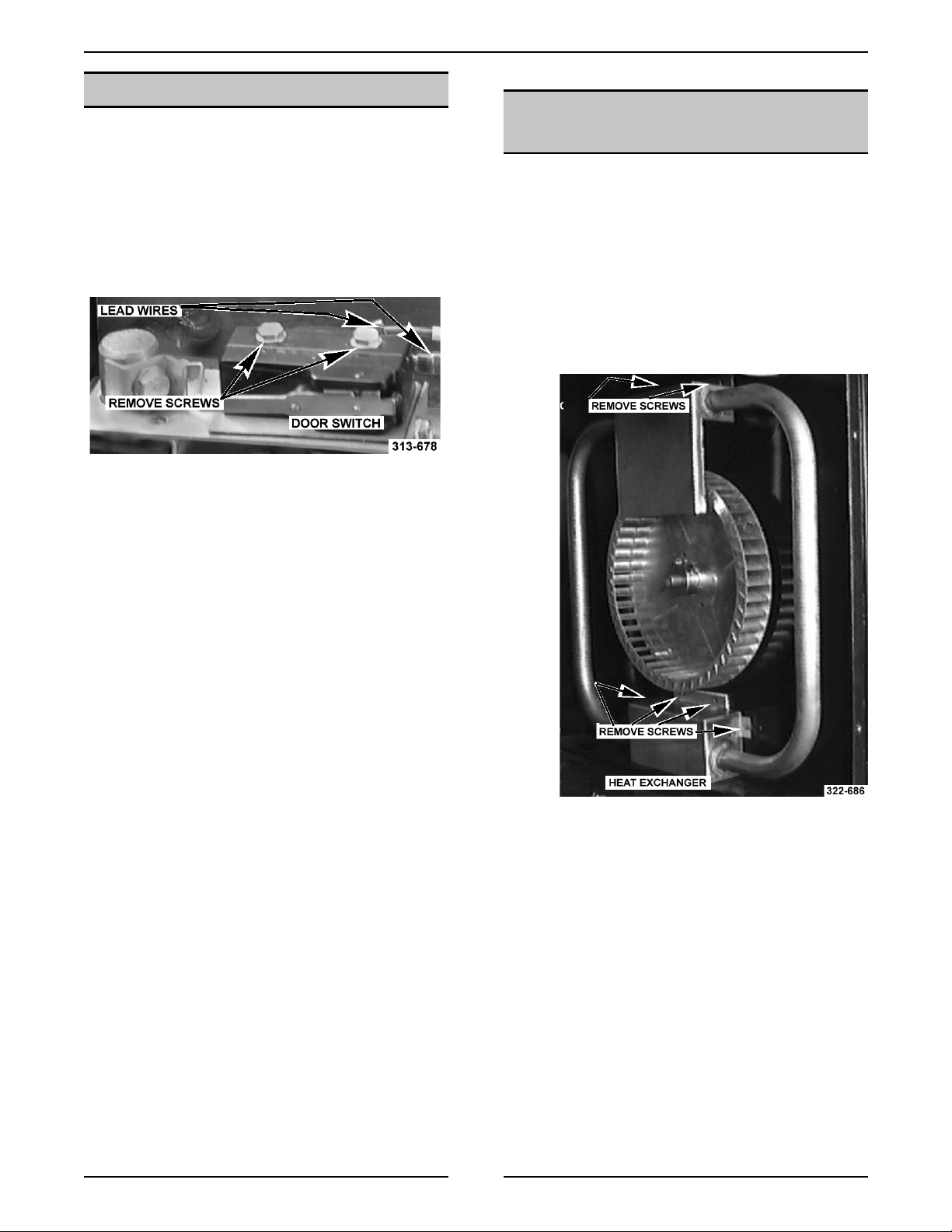
DOOR SWITCH
HEAT EXCHANGER (GAS
UNPLUG UNIT BEFORE SERVICING.
OVENS)
1. Rem ove the t op front cover as outlined under
"COVERS AND PANELS".
2. Disconnect the leads to the door switc h.
3. Rem ove the switch whic h is secured by two
screws.
4. Reverse the procedure to install t he new
switch.
5. Adj ust the door switch as outlined under
"DOOR SWITCH ADJUSTMENT" in
"SERVICE PROCEDURES AND
ADJUSTMENTS".
WARNING:
WARNING:
SERVICING THE UNIT.
1. Rem ove racks and the r ight rack support.
2. Rem ove baffle panel by lifting up and out.
3. Rem ove the screws that secure the heat
exchanger and remove it fr om the oven.
UNPLUG UNIT BEFORE SERVICING.
SHUT OFF THE GAS BEFORE
4. Reverse procedure to i nstall.
8
Page 9
HALF-SIZE CONVECTION OVENS - REMOVAL AND REPLACEMENT OF PARTS
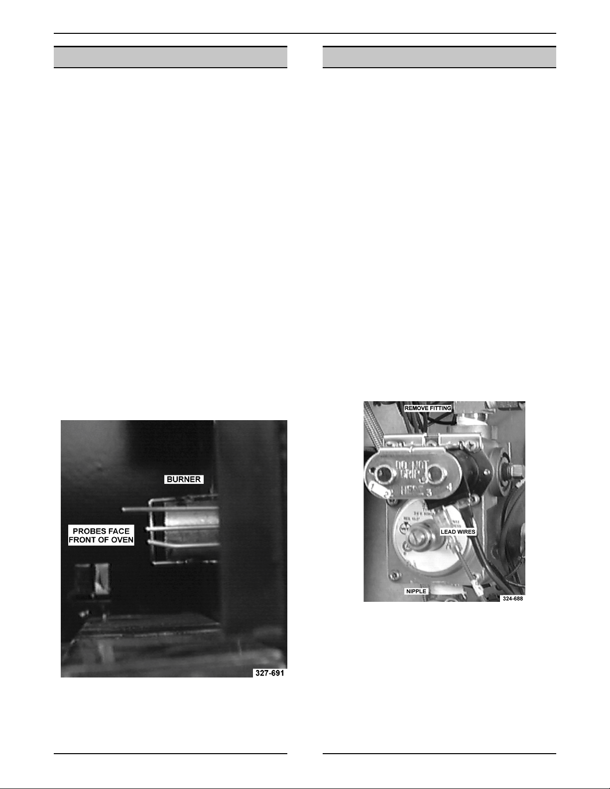
BURNER (GAS OVENS)
WARNING:
WARNING:
SERVICING THE UNIT.
1. Rem ove racks and the r ight rack support.
2. Rem ove baffle panel by lifting up and out.
3. Rem ove the right side panel as outlined under
“COVERS AND PANELS”.
4. Disconnect the lead wires to the electrode
assembly.
5. Rem ove the heat exchanger as outlined under
“HEAT EXCHANGER”.
6. Rem ove the screws from the burner brack et
and pull the bur ner into the oven cavity.
7. Rem ove the screws that secure the electrodes
to the burner brac k et.
UNPLUG UNIT BEFORE SERVICING.
SHUT OFF THE GAS BEFORE
GAS VALVE (GAS OVENS)
WARNING:
WARNING:
SERVICING THE UNIT.
WARNING:
DURING SERVI CING MUST BE CHECK E D FOR
LEAKS. CHECK WITH A SOAP AND WATER
SOLUTION (BUBBLES). DO NOT USE AN OPEN
FLAME.
A. CHECK ALL JOINTS PRIOR TO THE
B. CHECK ALL JOINTS BEYOND GAS
1. Rem ove the right side panel and control panel
as outlined under “COVERS AND PANELS”.
2. Disconnect the lead wires at the gas valve.
3. Disconnect the gas line fitting going to the
burner at the top of the gas valve.
UNPLUG UNIT BEFORE SERVICING.
SHUT OFF THE GAS BEFORE
ALL GAS JOINTS DISTURBED
GAS VALVE BEFORE LIGHTING UNIT.
VALVE AFTER UNIT IS LIT.
8. Reverse procedure to i nstall.
NOTE:
positioned toward t he front of the oven.
When installed, the electrodes are
4. Rem ove the gas valve from the nipple between
the it and t he manual gas valve.
5. Reverse procedure to i nstall.
6. Adj ust the gas valve as outlined under “GAS
PRESSURE ADJUSTMENT”.
9
Page 10
HALF-SIZE CONVECTION OVENS - REMOVAL AND REPLACEMENT OF PARTS
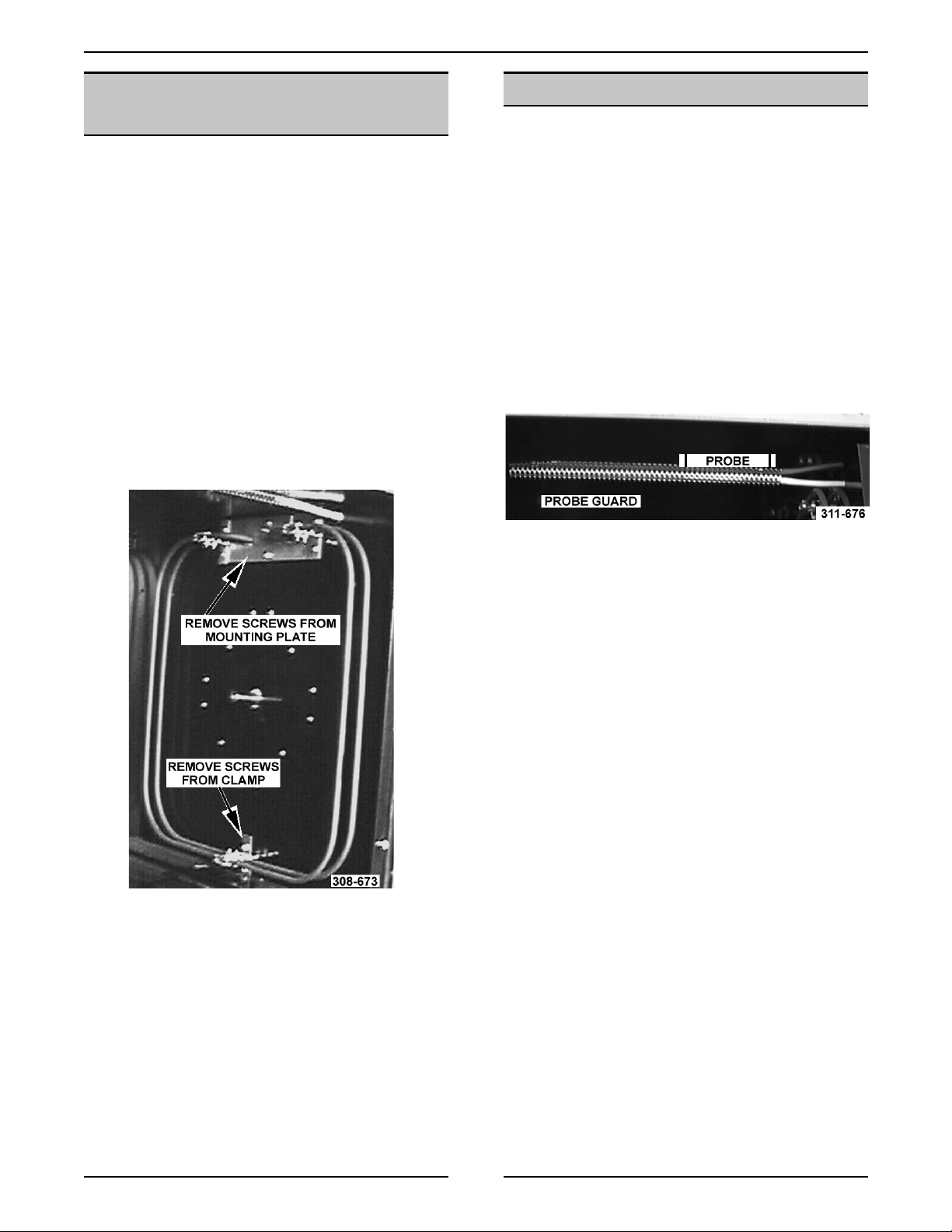
HEATING ELEMENTS
(ELECTRIC OVE NS)
WARNING:
POWER TO T HE MACHINE AT THE MAIN
CIRCUIT BO X. P LA CE A TAG ON THE CI RCUIT
BOX INDICATING THE CIRCUIT IS BEING
SERVICED.
1. Rem ove racks and the r ight rack support.
2. Rem ove baffle panel by lifting up and out.
3. Rem ove the right side panel as outlined under
“COVERS AND PANELS”.
4. Disconnect the lead wires to the heating
elements.
5. Rem ove the screws from the clamps that
secure the heating element assembly.
DISCONNECT THE ELECTRICAL
TEMPERATURE PROBE
Procedure
WARNING
1. Rem ove the control panel as outlined under
2. Disconnect the probe leads at the temperature
3. Rem ove probe from the pr obe guar d and push
NOTE:
the probe should be insert ed into the probe guard.
: UNPLUG UNIT BEFORE SERVICING.
"COVERS AND PANELS".
control.
it thru the oven wall into the control panel ar ea.
When installing, only the metal surface of
6. Pul l the top of the heating element assembl y
into the oven cavity until the ends of the
element s are inside the oven cav ity. Li ft up and
remove the lower clamp f r om between the side
wall and the bottom of the oven cavity.
NOTE:
angle. The hole in the inside oven cavit y wal l may
not line up straight with t he oven cavity outer shell.
4. Reverse the procedure to install t he new probe.
5. Adj ust the temperat ur e c ontrol as outlined
The probe may have to be inserted at an
under "TEMPER A TURE CONTROL
CALIBRATI ON" in "SERVICE PROCEDURES
AND ADJUSTMENTS".
7. Rem ove the clamps fr om the heati ng element
assembly and repl ac e the element ( s).
8. Reverse procedure to i nstall.
10
Page 11
HALF-SIZE GAS CONVECTION OVENS - SERVICE PROCEDURES AND ADJUSTMENTS
SERVICE PROCEDURES AND ADJUSTMENTS
WARNING:
MEASUREMENTS WHILE POWER IS APPLIED TO THE MACHINE. EXERCISE EXTREME CAUTION AT ALL
TIMES. IF TEST POI NT S ARE NOT EASI LY ACCESSIBLE, DISCONNECT POWER, ATTACH TEST
EQUIPMENT AND REAPPLY POWER TO TEST .
WARNING:
1. Rem ove the right side panel as outlined under
"COVERS AND PANELS".
2. Rem ove the probe lead wires from the
electronic control .
3. Test t he pr obe with an ohmmeter.
TEMPERA-
TURE
CERTAIN PROCEDURES IN THIS SECTION REQUIRE ELECTRICAL TEST OR
TEMPERATURE PROBE
TEST (ALL MODELS)
UNPLUG UNIT BEFORE SERVICING.
RESISTANCE
in ±10%
in (F
77 90000
240 4077
260 3016
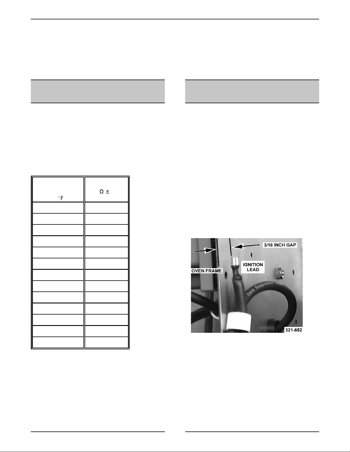
VERIFICATION OF SPARK
AT SPARK PROBE
WARNING:
WARNING:
SERVICING THE UNIT.
1. Rem ove the right side panel and control panel
as outlined under “COVERS AND PANELS”.
2. Disconnect the high voltage lead from the
electrode.
WARNING:
YOUR HANDS FO R THIS TEST. THE MANUAL
GAS VALVE MUST BE CLOSED.
3. Clamp the wire in such a manner that the end
of the wire is 3/16" fr om the f r ame of t he oven.
NOTE:
from the ov en or spark ing may not oc c ur even
though the probe ci rcuits are functioni ng pr oper ly.
UNPLUG UNIT BEFORE SERVICING.
SHUT OFF THE GAS BEFORE
DO NOT HOLD THE W IRE WITH
It is critical that the wire be held 3/16" away
280 2266
300 1726
320 1332
340 1041
360 822
380 656
400 529
425 424
450 334
475 266
WARNING:
POW E R TO BE APPLIED TO THE UNI T DURING
THE TEST. USE EXTREME CAUTION AT ALL
TIMES.
4. Pl ug the unit in and set the temperat ur e
controller to the maximum setting.
5. Turn the power switch on.
6. Sparking should occur after a 15 second purge
tim e. Arcing from the lead wire to the oven
frame should be observed at this time.
THE FOLLOWI NG ST EPS REQUIRE
11
Page 12
HALF-SIZE GAS CONVECTION OVENS - SERVICE PROCEDURES AND ADJUSTMENTS
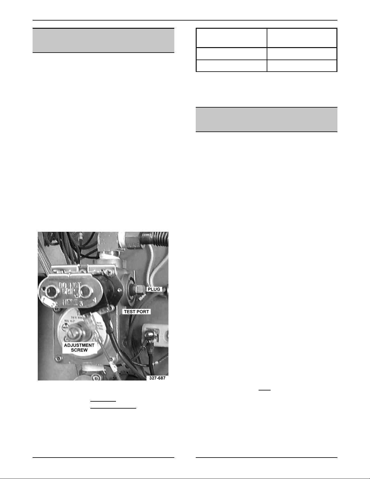
GAS PRESSURE
ADJUSTMENT
WARNING:
WARNING:
SERVICING THE UNIT.
1. Rem ove the right side panel and control panel
as outlined under “COVERS AND PANELS”.
2. Rem ove the plug from the test port and install
the manometer.
WARNING:
POW E R TO BE APPLIED TO THE UNI T DURING
THE TEST. USE EXTREME CAUTION AT ALL
TIMES.
3. Pl ug in the unit and turn on the gas.
4. Set the temperat ur e c ontrol to the highest
setting and turn the power switch on. The
burner must be lit while adjusting the pressure.
5. Turn the adjustment screw to obt ain the proper
gas pressure.
UNPLUG UNIT BEFORE SERVICING.
SHUT OFF THE GAS BEFORE
THE FOLLOWI NG ST EPS REQUIRE
GAS TYPE SETTING AT OUTPUT
OF GAS VALVE
Natural 3.5 inches W.C.
Propane 10 inches W.C.
NOTE:
10.5 (Propane) inches W. C., the desired output
cannot be obtained and the oven will overate at a
lower BTU.
If input pressure is below 4.0 (Natural) or
SPARK IGNITION CONTROL
TEST
WARNING:
NOTE:
to the oven ground.
No Gas Ignition & No Sparking
1. Rem ove the right side panel as outlined under
“COVERS AND PANELS”.
2. Pl ug in the unit and set the temperat ur e
controller to 350°.
3. Turn the power switch on.
UNPLUG UNIT BEFORE SERVICING.
Verify that the ground terminal is connected
• Turn screw clockwise
• Turn screw countercloc k wise
pressure.
to increase pressure.
to decrease
4. Check for 24 VAC between the power terminal
and ground terminal.
A. If 24 V A C is present, replace t he spark
ignition control.
B. If 24 V A C is not present, check t he
transformer, temperature contr oller, and
switches.
No gas ignition - sparking occurs
1. Rem ove the right side panel as outlined under
“COVERS AND PANELS”.
2. Pl ug in the unit and set the temperat ur e
controller to 350°.
3. Turn the power switch on.
4. Check for 24 VAC between the gas valve
terminal and the ground terminal. The voltage
should be present after
and during the 10 second i gnition period.
A. If 24 V A C is present, check the gas valve
and gas supply.
B. If 24 V A C is not present, replac e the spark
ignition control.
the 15 second purge
12
Page 13

HALF-SIZE GAS CONVECTION OVENS - SERVICE PROCEDURES AND ADJUSTMENTS
ELECTRONIC CONTROL
SPECIAL KEY FUNCTIO NS
functions press the specifi ed k ey s whil e turning the
oven on. Y ou c an not toggle between functions.
Each function has to be entered from the off
position.
NOTE:
See diagram foll owi ng the table.
CALIBRATE OVEN
1. Pl ac e a thermocoupl e near the geometric
2. Cycle oven until the cavity temperature stabiliz-
3. Turn the oven off.
4. Enter the calibration mode.
There are f our hidden keys on the contr ol.
HOLD KEYS 1 & 3 4 & 9 6 & 8
FUNCTION Calibration Mode Change between (C & (F Display test
- Perfor m Calibration at 350(F
center of the oven cavity.
es. (usually 3 cycles)
- To activate these
5. Com par e the set temperat ur e to the measured
temperature.
6. Adj ust the temperat ur e on the display to match
the measured temperature.
7. Press key 3 to store the calibration information.
DISPLAY TEST
continuous test unt il the oven is turned off. Each
segment of the displays will be lit in sequence, each
LED in order and then eac h digit will light.
ERROR CODES
- The control will cycle through a
CODES CONDITIONS
E-01 High Limit Error - Check open probe.
E-02 Low Limit Error - check for 6 VAC from tr ansformer.
Check control pins 1-2 for 12 V A C & pins 2-3.
E-03 Control compartm ent ambient temperature is above 215(F
E-04 Control compartm ent ambient temperature is below 32(F
13
Page 14

HALF-SIZE GAS CONVECTION OVENS - SERVICE PROCEDURES AND ADJUSTMENTS
SOLID STATE CONTROL
TEST
NOTE:
1. Rem ove the screws from the control panel and
2. Pl ac e a thermocoupl e in the geomet r ic center
3. Set the temperat ur e to the maximum setting.
4. Turn the power switch to ON.
Ov en temperature must be below 450(F.
pull the c ontrol panel away from the oven to
access the control wir ing.
of the oven cavity.
SOLID STATE CONTROL
CA LIBRATION
1. Pl ac e a thermocoupl e in the geomet r ic center
of the oven cavity.
2. Set the On-Off-Cool Down switch to ON.
3. Set the temperat ur e c ontrol to 350 degrees F.
4. Allow the oven to cycle until the oven
temperature stabilizes. (cycle at least three
times)
5. Record t he temperature at which the HEAT
LIGHT goes of f and on.
A. Check f or at least two com plete heating
cycles.
6. Calc ulate the differ ential by subtrac ting the
temperat ure indicat ed when the heat light
comes on from the temperature i ndicated when
the heat light goes out.
5. Check for supply voltage acr oss:
200-240 volts - pin 10 to pin 6
120 volts - pin 9 to pi n 6
A. If c orrect, proceed to step 7.
B. If incorrect, go to step 6.
6. Check for supply voltage acr oss:
200-240 volts - pin 7 to pin 10 and pin 8 to pi n
10
120 volt - pin 7 to pin 9 and pin 8 to pi n 9
A. If c orrect, proceed to step 7.
B. If incorrect, problem is not with the
temperat ure control. Return to Troubl eshooting Guide.
7. Turn the temperat ur e c ontrol to the minimum
setting.
NOTE:
8. Check for zero (O) Volts across:
Ov en temperature must be abov e 300(F.
200-240 volts - pin 6 to pin 10
120 volt - pin 6 to pin 9
A. If c orrect the problem is not wit h the
temperat ure control. Return to Troubl eshooting Guide.
Differenti al = Heat l ight OFF - Heat light ON.
Exam ple: 360 (light out) - 340 (light on) = 20( F
differential.
A. The differential calculated should be
less than 20 degrees F.
(1) If t he differential is more than 20
degrees F, check t emperature
probe and temperature control
board as outlined under
"TEMPERATURE PROBE
TEST" and " S OLID STATE
CONTROL TE S T".
7. Calc ulate the average tem per ature by adding
the temper ature indic ated when the heat light
goes out to the temperature indicated when the
heat light comes on and dividi ng this answer by
2.
[Temp.(light off) + Temp. ( light on)] ÷ 2 = Average
Temperature
Exam ple: (360 + 340) ÷ 2 = 700 ÷ 2 = 350( F
average temperature
B. If incorrect, replace the t emperature
control.
14
Page 15

HALF-SIZE GAS CONVECTION OVENS - SERVICE PROCEDURES AND ADJUSTMENTS
8. If the average temper ature dif fers more t han 10
degrees F from the dial settings:
A. Pencil mark t he k nob pointer position as a
reference point on the control panel next
to the dial plate.
B. Remove the temperature control knob.
C. Loosen the two dial plate mounting screws
and the temper ature control mounting nut .
Loosen only enough to turn the dial pl ate.
DOOR SWITCH
ADJUSTMENT
WARNING:
POWER TO T HE MACHINE AT THE MAIN
CIRCUIT BO X. P LA CE A TAG ON THE CI RCUIT
BOX INDICATING THE CIRCUIT IS BEING
SERVICED.
1. Rem ove the upper front cover as outlined
under "COVERS A ND P A NE LS " .
2. The door switc h ac tuator should be operated by
the switch lever when the door is about ½" from
being closed.
3. If adjustm ent is necessary, use the following
procedures.
A. Loosen the two switch mount ing screws.
B. Adjust t he switc h br ac k et to obtain t he
DISCONNECT THE ELECTRICAL
correct sett ing as outlined in step 2.
D. Rotate the dial plate until the temper ature
calculated in step 7 is in line with the
pencil mark.
E. If the above adjustment cannot be
obtained, chec k temperat ur e pr obe and
temperat ure control board as outlined
under "TEST ING TEMPERATURE
CONTROL BO A RD" .
C. Tighten the two switch bracket mounti ng
screws.
D. If the adjustment can not be obt ained by
moving the switch, you can bend the tab
of the actuator lever.
4. Install the upper front cover.
15
Page 16

HALF-SIZE GAS CONVECTION OVENS - SERVICE PROCEDURES AND ADJUSTMENTS
DOOR REVERSAL
WARNING:
POWER TO T HE MACHINE AT THE MAIN
CIRCUIT BO X. P LA CE A TAG ON THE CI RCUIT
BOX INDICATING THE CIRCUIT IS BEING
SERVICED.
1. Rem ove the door as outlined under “OVEN
DOOR”.
A. Remove the door strike plate from t he top
B. Rotate the door 180 °. The top of the door
C. Install the door strike on the new top of the
2. Rem ove the bot tom door bushing and antirotation plate.
DISCONNECT THE ELECTRICAL
of the door.
is now the bottom .
door. Use the screws removed to instal l
the strike plate to fill the holes on the
bottom of the door.
7. Rem ove the door switc h from the switch
mounti ng bracket.
A. Use the other set of holes in the mounting
bracket to mount the switch.
B. Place the switch insulation pad on the
mounti ng bracket.
3. Remove the knockout from the lower sill cover.
4. Install the plug button in the old door bushing
hole in the lower sill cover.
5. Install the bott om door bushing and anti rotation plate.
6. Rem ove the catch assembly from the oven.
A. Move the door catch to the opposite side
of the door c atch channel.
B. Install the door catch assembly to the
opposite side of the top sill.
C. Install the switch ont o the mounti ng
bracket.
8. Install the door i n the lower door bushing.
9. Install the top door bushi ng and door switch
mounti ng plate to the new position on the upper
sill.
10. Adjust the door as outlined under “DOOR
ADJUSTMENT”.
11. Adjust the door switc h as outlined under
“DOOR SWITCH ADJUSTMENT”.
12. Replace the t op front cover and check the oven
for proper operation.
16
Page 17

HALF-SIZE GAS CONVECTION OVENS - SERVICE PROCEDURES AND ADJUSTMENTS
DOOR ADJUSTMENT
WARNING:
1. The door shoul d be par allel wit h the face of the
oven cavity.
2. If adjustm ent is needed:
A. Remove the top front cover as outlined
B. Loosen the screws that secure the door
UNPLUG UNIT BEFORE SERVICING.
under “COVERS AND PANELS” in
“REMOVAL AND REPLACEMENT OF
PARTS”.
support and move the door in the slot unti l
it is parallel wit h the face of the oven
cavity.
BLOWER ADJUSTMENT
WARNING:
POWER TO T HE MACHINE AT THE MAIN
CIRCUIT BO X. P LA CE A TAG ON THE CI RCUIT
BOX INDICATING THE CIRCUIT IS BEING
SERVICED.
1. Rem ove rack and r ac k support s.
2. Rem ove baffle panel by lifting up and out.
3. Check t he blower. It should be ¼" away from
and parallel to the oven wall. If not, proceed to
step 4.
4. Rem ove the right side panel as outlined under
“COVERS AND PANELS”.
5. To adjust the blower at the sides (front and rear
of oven cavity), loosen the motor mounting
bolts and move the motor until the ¼" gap is
obtained.
6. To adjust the blower at the t op and bottom,
place shims between the motor mounting
bracket and the mounting base.
DISCONNECT THE ELECTRICAL
C. Tighten the screws and install the top front
cover.
7. Reverse the procedure to install.
HEATING ELEMENT TEST
Test each rod in the element assembly.
Values in the table are nominal (± 10%).
VOLTAGE WATTS AMPS RESISTANCE
208 2500 12 17.33
240 2500 10.4 23.1
17
Page 18

HALF-SIZE CONVECTION OVENS - ELECTRICAL OPERATION
ELECTRICAL OPERATION
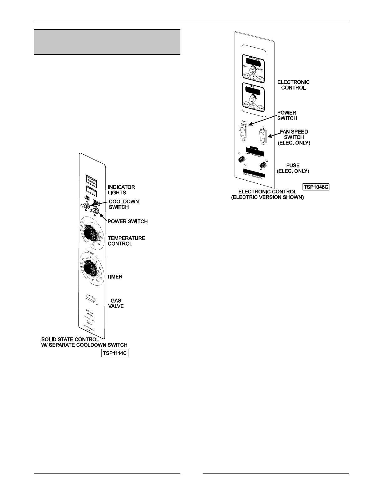
COMPONENT FUNCTION
POWER SWITCH.............Controls power to oven.
COOLDOWN SWITCH ......... Prevents heaters from operating and allows fan to run. (On some sol id state
control models, this switch is combined with the power switch)
FAN SPEED SWITCH .......... Controls speed of oven cavity blower motor. ( E lectric ovens)
SOLID STATE CONTROL.......Controls oven temperature.
TIMER .....................Signals end of timed baking. Does not shut heater or bur ner off. (Solid state
control)
ELECTRONIC CONTROL.......Controls oven temperature, cook and hold mode, pulse mode and time.
BLOWER MOTOR ............Circulates air inside oven cavity. (Contains centrifugal switch for gas ovens)
(2 speed electric ovens)
DOOR SWITCH ..............Allows heating of oven, only when the doors are closed.
TEMPERATURE PROBE ....... Senses temperature of oven cavity for the solid state control and elect r onic
control.
SOLID STATE RELAY .........Controls power to blower motor. (Electronic Control)
TRANSFORMER..............Provides 12 and 6 VAC power. (E lectronic Control)
TRANSFORMER..............Provides 24 VAC power to the spark ignition control if the centrifugal switch
(part of blower motor) is closed. (Gas Ovens)
GAS VALVE ................. Allows gas to flow to burner. (Gas ovens)
SPARK MODULE .............Generates spark for burner ignit ion, monitors fl ame, controls 15 second
purge time and 10 second ignition time and power to gas valve. (Gas ovens)
POWER LIGHT............... Lit whenev er the power switch is ON. (Solid state contr ol)
HEAT LIGHT.................Lit whenever burner or heater s are operating. (Solid state cont r ol)
NO IGNITION LIGHT ..........Lit when sensor fails to detect flame. (Solid state control - Gas ov en)
CONTACTOR ................Powers heater elements. (E lectric ovens)
FUSE ..................... Protects control circuit. (Electric ovens)
18
Page 19

HALF-SIZE CONVECTION OVENS - ELECTRICAL OPERATION
COMPONENT LOCATION
19
Page 20

HALF-SIZE CONVECTION OVENS - ELECTRICAL OPERATION
SEQUENCE OF OPERATION
Ignition Module
1. 24VAC supplied to ignit ion module as described
under oven sequence of operation
A. 15 second prepurge period
1) No-i gnition light is on
2) Cavit y blower motor removes any
residual gas from combustion chamber
B. 10 second spark period
1) Gas valv e energized
2) No-i gnition light is off
2. The flam e is monitored by a DC voltage of at least 5
microamps passing from the ignitor probe through
the flame to ground.
A. If the flam e is detected before 10 seconds:
1) Sparki ng is terminated
2) G as val ve held open
3) Monit or ing of flam e conti nues
B. If a flame is not established after the 10
second spark period
1) a second 15 second prepurge period
2) A second 10 second spark period
C. If a f lame is not establis hed after the second
10 second spark period
1) a t hi r d 15 second prepurge period
2) A thi r d 10 second spark period
D. If a f lame is not establi shed aft er the thir d 10
second spark period, the module will go into
lock out
1) No ignition light on
Gas Oven
NOTE:
A combinati on of terminal numbers and wire
numbers will be used to describe the circuit paths. The
complete path will be described when a component is
energized.
Solid S t ate Control ( Gas)
NOTE:
Use GCO2D Schematic
1. Conditions
A. Supply voltage to unit
1) L1 t o power switch: wir e #1; J1-1; wire #1
2) L2 t o power switch: wir e #2; J1-2; wire #2
3) G ood chassi s gr ound f or :
a. Ignit ion module: GND
b. No ignit i on light: wire #48; GND;
wire #6; J1-6; wire #6; GND
c. Gas valve: wire #48; GND;
d. Ignit ion transformer: GND
B. Power switch off
C. Oven at room temperature
D. Temperatur e control off
E. Manual gas valve open
F. Door swit ch cl osed
G. Cooldown switch off
H. T imer of f
2. Power switch turned "on" (voltage at terminals of
power switch)
A. Power On lamp lights: wire #34/J1; wire
#41/37
B. Control powered: wire #34; wire #33/3; J1-3;
wire #3; door switch; wir e #27/4; J1- 4; wi r e
#4/36/35; terminal 8; terminal 9 (120 VAC) or
terminal 10 ( 200- 240 VAC); wi r e #39/37
C. Blower m ot or energized: wire #34; wire #33/3;
J1-3; wire #3; door switch; wi r e #27/4; J1- 4;
wire #4/11; J1-11; wire #11; wir e #13/7; J1- 7;
wire #7/37
1) Blower m otor reaches operating speed,
blower motor centrif ugal swi t ch closes
3. To reset the ignition module perform one of the
following
A. Turn power switch off; then on
B. Open and close the door
C. Turn t he temperatur e control all the way off
then back to the set temperature
4. If a f l ame is established then is extinguished before
the temperature control is sat i sf ied, the no ignition
light will be on and the ignition module will attempt
to light t he burner in the sequence described above.
3. Control set to cook t em perature, contacts 6/7 close
A. Ignition t r ansformer primary powered: terminal
6; wire #9; J1-9; wire #9; BK/BL wire; WH/BK
wire; wire #7; J1-7; wire #7/37
B. Heating lamp l i ght s: terminal 6; wire #43; wire
#42/37
4. 24 VAC from ignition tr ansf or mer secondary to
ignition module: transformer secondary wire #52;
centrifugal switch; wire #54; terminal 24V of control
module; GND
5. Ignit ion module operates (see ignition module
sequence of operation)
20
Page 21

HALF-SIZE CONVECTION OVENS - ELECTRICAL OPERATION
6. Temperature is sati sf ied and control contacts 6/7
open
A. Heat light goes out.
B. Power removed from ignit ion transformer.
7. Ignit ion module de-energized
A. Gas valve de-energized, gas supply to burner
off.
8. Oven cycles on solid state control unt il power switch
is moved from the "on" position or the door is
opened.
NOTE:
The blower motor, heat lamp and gas valve
are de-energized when the door is opened during
the heat mode.
Solid S t ate Timer (Gas)
NOTE:
Use GCO2D Schematic
NOTE:
The timer is not connected to the heating circui t
and will not prevent the oven from heating when time
expires.
1. Power switch on
2. Time dialed into tim er, cont act s 1/ 3 cl ose.
A. Timer motor energized: wire #34/64; tim er
contacts 1/3; wht wi r e; wire #37
3. Time expires.
A. Contacts 1/3 open
1) Timer motor de-energized
B. Contacts 1/4 close
4. Buzzer sounds: wire #34/64; timer contacts 1/4; wire
#66; wire #65/37
Electronic Control ( Gas)
NOTE:
Use GCO2C Schematic
NOTE:
A combinati on of terminal numbers and wire
numbers will be used to describe the circuit paths. The
complete path will be described when a component is
energized.
Heat
1. Conditions.
A. Supply voltage to unit.
1) L1 t o power/cool down swit ch: wi r e #1;
J1-1; wire #1
2) L2 t o:
a. Motor: wire #2; J1-2; wire #2; J1-7;
wire #7/13
b. Primary of ignit ion transformer: wire
#2; J1-2; wire #2; J1-7; wire #7
c. Primary of control transformer: wire
#2; J1-2; wire #2; J1-7; wir e #7/97
3) G ood chassi s gr ound: ignition module
transformer
a. Ignit ion module: GND
b. Electronic cont r ol : terminal 8 of
control; J2-8; J1-6; wire #6; GND
c. Gas valve: wire #48; GND
d. Ignit ion transformer: GND
B. Power/cooldown “off".
C. Oven at room temperature.
D. Door switch cl osed.
E. Manual gas valve open.
2. Power/cooldown switch turned "on"
A. Control transf or mer primar y powered: wire
#26/4; J1-4; wir e #4/94; wi r e #97/7; J1- 7; wire
#2; J1-2; wire #2; L2
5. Timer turned to off.
A. Contacts 1/4 open
1) buzzer de-energized
Cooldown (Gas/Solid State Control)
NOTE:
Use GCO2D Schematic
1. Conditions
A. Oven tem perature needs to b e lowered.
B. Power swit c h o n
2. Cooldown switch on
A. Blower motor energized: power switch; wire
#34/33/36/11; J1-11; wire #11; wire #13/7; J17; wire #7/37; power switch
3. Control powered from secondary of cont r ol
transformer:
A. 6 VAC - wire #16; J1-16; J2-3; J2-2; J1- 15;
wire #15
B. 12 VAC - wire #14; J1-14; J2-1; J2-2; J1- 15;
wire #15
4. Control set to desired temperatur e
A. Control verifi es heat mode: 16 to 18 VDC
output on J2-11; J1-20; wi r e #20/21;
power/cooldown switch; contacts of swi t ch ar e
open and no return voltage to J2-5
B. Control verifies that door i s closed: 16 to 18
VDC output on J2-11; J1-20; wir e #20/27; door
switch; wire #3; J1-3; J2-4
21
Page 22

HALF-SIZE CONVECTION OVENS - ELECTRICAL OPERATION
5. After verification of heat mode and door closed:
A. Ignition t r ansformer primary powered: wire
#26/43; J2-13; J2-15; J1- 5; wi r e #5; BK/BL
wire; WH/BK wire; wire #7; J1-7; wire #2; J12; W i r e #2; L2
1) 24 VAC from secondary of igniti on
transformer to ignition module: wire #52;
centrifugal switch; wi r e #54; terminal 24V
of control module; GND
B. Solid state relay energized: 16 to 18 VDC
output on J2-11; J1-20; wi r e #20; wir e #19;
J1-19; J2-10
1) Blower motor energized: wire #26/4; J1-4;
wire #4/34; ss relay contacts; wir e #9; J19; wire #11; J1-11; wir e #11; wire #13/7;
J1-7; wire #2; J1-2; Wire #2; L2
a. Blower motor r eaches operating
speed, blower motor centrifugal
switch closes
6. Ignit ion module operates (see ignition module
sequence of operation)
7. Oven cycles on electronic control until
power/cooldown switch is m oved from the "on"
position, a di f ferent mode is selected or the door is
opened.
NOTE:
The blower motor is de-energized and gas
valve closed when the door is opened while the oven
is in the heat mode.
Cook and Hold
1. Conditions
A. Oven in prehea t.
2. A bake temperature and tim e is set.
3. A hold temperatur e and time is set and start key
pressed.
4. Oven cycles at set temperature.
NOTE:
In pulse mode (init iated at the beginning of the
bake cycle), the blower motor is operated in 45 second
cycles, with the first cycl e being off then 45 seconds on.
The pulse time cannot be longer than the bake time.
5. Time expires in cook mode.
A. Buzzer sounds (short beep).
B. Control lowers temperatur e to hol d
temperature.
6. Oven temperature reaches hold temperature.
A. Display counts up time and flashes "hold"
7. Oven continues to cycle at hold t emperatur e unti l
oven is turned off or the hold function is turned off.
NOTE:
The blower motor and gas valve are deenergized when the door is opened while the oven is
in the hold mode.
Cook
1. Conditions
A. Oven in prehea t.
2. Temperature is set.
3. Time is set and start key pressed.
4. Oven cycles at set temperature.
NOTE:
In pulse mode (init iated at the beginning of
the bake cycle), the blower motor is operated in 45
second cycles, with the first cycle being off then 45
seconds on. The pulse time cannot be longer than
the bake time.
5. Time expires.
A. Buzzer sounds continuall y unt il turned off.
6. Oven continues to cycle at set temperature.
NOTE:
The blower motor and gas valve are deenergized when the door is opened while the oven is
in the cook mode.
Cooldown (Gas/Electronic Control)
NOTE:
Use GCO2C Schematic
1. Conditions
A. Cooking completed, oven temperature needs
to be lowered.
B. Power/cooldown switch on
2. Power/cooldown switch to cool down
A. Control transf or mer primar y powered: wire
#26/4; J1-4; wir e #4/94; wi r e #97/7; J1- 7; wire
#2; J1-2; wire #2; L2
3. Control powered from secondary of cont r ol
transformer:
A. 6 VAC - wire #16; J1-16; J2-3; J2-2; J1- 15;
wire #15
B. 12 VAC - wire #14; J1-14; J2-1; J2-2; J1- 15;
wire #15
4. Control verifies cooldown mode: 16 to 18 VDC
output on J2-11; J1-20; wi r e #20/21;
power/cooldown switch; wire #29; J2-5
22
Page 23

HALF-SIZE CONVECTION OVENS - ELECTRICAL OPERATION
5. After verification of cooldown m ode:
A. Solid state relay energized: 16 to 18 VDC
output on J2-11; J1-20; wi r e #20; wir e #19;
J1-19; J2-10
1) Blower motor energized: wire #26/4; J14; wire #4/34; ss relay contacts; ; wi r e # 9;
J1-9; wire #11; J1-11; wir e #11; wir e
#13/7; J1-7; wir e #2; J1-2; wi r e #2; L2
B. Contactor coil will not be energized.
C. The door position signal is not r ead.
Electric Oven
NOTE:
A combinati on of terminal numbers and wire
numbers will be used to describe the circuit paths. The
complete path will be described when a component is
energized.
Solid State Control (Elec)
NOTE:
Use ECO2D Schematic
1. Conditions.
A. Fuses are good.
B. Supply voltage to unit ( t hr ee phase)
B. Control powered: wire #34; wire #33/3; J1-3;
wire #3; door switch; wir e #27/4; J1- 4; wi r e
#4/36/35; terminal 8 and 7; terminal 9 (120
VAC) or terminal 10 ( 200- 240 VAC); wi r e
#39/37
C. Blower m ot or energized: wire #34; wire #33/3;
J1-3; wire #3; door switch; wi r e #27/4; J1- 4;
wire #4; motor speed switch; wir e #11 high or
12 low ); J1-(11 hi gh or 12 low); wire #(11 high
or 12 low); wire #13/7; J1- 7; wi r e #7/37
3. Control set to cook t em perature contacts 6/ 7 cl ose
A. Contactor coil energized: terminal 6; wire
#9; J1-9; wire #9/50; wi r e #52/7; J1- 7;
wire #7/37
B. Heating lamp l i ght s: terminal 6; wire #43;
wire #42/37
4. Heating elements energized
A. L1; wire #61; C1; Wire #70; wire #75; C3; Wire
#64; L3
B. L1; wire #61; C1; Wire #74; wire #71; C2; Wire
#62; L2
5. Oven reaches set temperature and control contacts
6/7 open
1) L1 to power switch: wire #1; J1-1; fuse;
wire #1A and one side of heater contacts
C1: wir e #61
2) L2 t o one side of heater contacts C2: wire
#62
3) L3 to power switch: wire #2; J1-2; fuse;
wire #2A and one side of heater contacts
C31: wire #64
4) G ood chassi s gr ound
C. Po wer s witch "of f"
D. Oven at room temperature
E. Solid state control of f
F. Door swit ch cl osed
G. Fan speed switch in either position
H. Cooldown switch off
J. Timer off
2. Power switch turned "on" (voltage at terminals of
power switch)
A. Power removed from contactor coi l
1) Heating elements de-energized
B. Heating lamp goes out.
6. Oven cycles on solid state control unt il power switch
is moved from the "on" position or the door is
opened.
NOTE:
The blower motor and heating elements are
de-energized when the door is opened and the oven
is in the heat mode.
Solid S t ate Timer (E lec)
NOTE:
Use ECO2D Schematic
NOTE:
The timer is not connected to the heating circui t
and will not prevent the oven from heating when time
expires.
1. Power switch on
2. Time dialed into tim er, cont act s 1/ 3 cl ose.
A. Timer motor energized: wire #34/64; tim er
contacts 1/3; wht wi r e; wire #37
3. Time expires.
A. Power On lamp lights: wire #34/J1; wire
#41/37
A. Contacts 1/3 open
1) Timer motor de-energized
B. Contacts 1/4 close
23
Page 24

HALF-SIZE CONVECTION OVENS - ELECTRICAL OPERATION
4. Buzzer sounds: wire #34/64; timer contacts 1/4; wire
#66; wire #65/37
5. Timer turned to off.
A. Contacts 1/4 open
1) buzzer de-energized
Cooldown (Elec/Solid State Control)
NOTE:
Use ECO2D Schematic
1. Conditions
A. Cooking completed, oven temperature needs
to be lowered.
B. Power swit c h o n
2. Cooldown switch on
A. Blower motor energized: power switch; wire
#34/33/36/ m ot or speed switch; wir e #11 high
or 12 low ); J1-( 11 hi gh or 12 low); wire #(11
high or 12 low); wi r e #13/7; J1- 7; wire #7/37;
power switch
Electronic Control ( E lec)
C. Power/cooldown switch "off "
D. Oven at room temperature
E. Door switch closed
F. Fan speed switch in either position
2. Power/cooldown switch turned "on"
A. Control transf or mer primar y powered: wire
#26/4; J1-4; wir e #4/94; wi r e #97/7; J1- 7; wire
#7/2A; fuse; J1-2; wire #2; L3
3. Control powered from secondary of cont r ol
transformer:
A. 6 VAC - wire #16; J1-16; J2-3; J2-2; J1- 15;
wire #15
B. 12 VAC - wire #14; J1-14; J2-1; J2-2; J1- 15;
wire #15
4. Control set to desired temperatur e
A. Control verifi es heat mode: 16 to 18 VDC
output on J2-11; J1-20; wi r e #20/21; J1-21;
power/cooldown switch; contacts of swi t ch ar e
open and no return voltage to J2-5
B. Control verifies that door i s closed: 16 to 18
VDC output on J2-11; J1-20; wir e #20/27; door
switch; wire #3; J1-3; J2-4
NOTE:
Use ECO2C Schematic
NOTE:
A combinati on of terminal numbers and wire
numbers will be used to describe the circuit paths. The
complete path will be described when a component is
energized.
Heat
1. Conditions
A. Fuses are good.
B. Supply voltage to unit ( t hr ee phase)
1) L1 t o power/cool down swit ch: wi r e #1;
J1-1; fuse; wire #1A/1 and one side of
heater contacts C1: wire #61
2) L2 t o one side of heater contacts C2: wire
#62
3) L3 t o:
a. Motor: wire #2; J1-2; fuse; wire
#2A/7; J1-7; wire #7/13
b. Contactor coi l : wi r e #2; J1-2; f use;
wire #2A/7; J1-7; wire #7/50
c. Primary of control transformer: wire
#2; J1-2; fuse; wire #2A/7; J1-7;
wire #7/97
d. one side of heater contacts C3: wire
#64
4) G ood chassi s gr ound electroni c cont r ol :
terminal 8 of control; J2-8; J1- 6; wi r e #6;
GND
5. After verification of heat mode and door closed,
A. Solid state relay energized: 16 to 18 VDC
output on J2-11; J1-20; wi r e #20; wir e #19;
J1-19; J2-10
1) Blower motor energized: wire #26/4; J14; wire #4/34; ss relay contacts; ; wir e #
(11 high or 12 low ); J1- ( 11 high or 12
low); wire #(11 high or 12 l ow) ; wi r e
#13/7; J1-7; wir e #7/37
B. Contactor coil energized: wire #43; J2-13; J2-
15; J1-5; wire #5; wire #50/7; J1- 7; wi r e
#7/2A; fuse; J1-2; Wire #2; L3
1) Heating el ements energized
a. L1; wire #61; C1; Wire #70; wir e
#75; C3; W ire #64; L3
b. L1; wire #61; C1; Wire #74; wir e
#71; C2; W ire #62; L2
6. Oven reaches set temperature
A. Power removed from contactor coi l
1) Heating elements de-energized
7. Oven cycles on electronic control until
power/cooldown switch is m oved from the "on"
position or t he door is opened.
NOTE:
The blower motor and heating elements are
de-energized when the door is opened and the oven
is in the heat mode.
24
Page 25

HALF-SIZE CONVECTION OVENS - ELECTRICAL OPERATION
Cook
1. Conditions
A. Oven has reached set temperature in heat
mode
2. Time is set and start key pressed.
3. Oven cycles at set temperature.
NOTE:
In pulse mode (init iated at the beginning of
the bake cycle), the blower motor is operated in 45
second cycles, with the first cycle being off then 45
seconds on. The pulse time cannot be longer than
the bake time.
4. Time expires.
A. Buzzer sounds continuall y .
5. Oven continues to cycle at set temperature.
NOTE:
The blower motor and heaters are deenergized when the door is opened and the oven is
in the cook mode.
Cook and Hold
1. Conditions
A. Oven has reached set temperature in heat
mode
2. A bake temperature and tim e is set.
3. A hold temperatur e and time is set and start key
pressed.
4. Oven cycles at set temperature.
NOTE:
In pulse mode (init iated at the beginning of
the bake cycle), the blower motor is operated in 45
second cycles, with the first cycle being off then 45
seconds on. The pulse time cannot be longer than
the bake time.
Cooldown (Elec/Electronic Control)
NOTE:
Use ECO2C Schematic
1. Conditions
A. Cooking completed, oven temperature needs
to be lowered.
B. Power/cooldown switch on
2. Power/cooldown switch to cool down
A. Control transf or mer primar y powered: wire
#26/4; J1-4; wir e #4/94; wi r e #97/7; J1- 7; wire
#7/2A; fuse; J1-2; wire #2; L3
3. Control powered
A. 6 VAC from secondary of control transformer -
wire #16; J1-16; J2-3; J2-2; J1-15; wire #15
B. 12 VAC from secondary of control transformer
- wire #14; J1-14; J2-1; J2- 2; J1-15; wire #15
4. Control verifies cooldown mode: 16 to 18 VDC
output on J2-11; J1-20; wi r e #20/21;
power/cooldown switch; wire #29; J2-5
5. After verification of cooldown m ode:
A. Solid state relay energized: 16 to 18 VDC
output on J2-11; J1-20; wi r e #20; wir e #19;
J1-19; J2-10
1) Blower motor energized: wire #26/4; J14; wire #4/34; ss relay contacts; ; wir e #
(11 high or 12 low ); J1- ( 11 high or 12
low); wire #(11 high or 12 l ow) ; wi r e
#13/7; J1-7; wir e #7/37
B. Contactor coil will not be energized.
C. The door position signal is not r ead.
5. Time expires in cook mode.
A. Buzzer sounds (short beep).
B. Control lowers temperatur e to hol d
temperature.
6. Oven temperature reaches hold temperature.
A. Display counts up time and flashes "hold"
7. Oven continues to cycle at hold t emperatur e unti l
oven is turned off or the hold function is turned off.
NOTE:
The blower motor and heating elements are
de-energized when the door is opened and the oven
is in the hold mode.
25
Page 26

HALF-SIZE CONVECTION OVENS - ELECTRICAL OPERATION
SCHEMATICS GAS OVENS
GCO2D
26
Page 27

GCO2C
HALF-SIZE CONVECTION OVENS - ELECTRICAL OPERATION
27
Page 28

HALF-SIZE CONVECTION OVENS - ELECTRICAL OPERATION
WIRING DIAGRAM - GAS
OVENS
GCO2D - Control Section
28
Page 29

HALF-SIZE CONVECTION OVENS - ELECTRICAL OPERATION
GCO2D - Oven Section
29
Page 30

HALF-SIZE CONVECTION OVENS - ELECTRICAL OPERATION
GCO2C - Control Section
30
Page 31

HALF-SIZE CONVECTION OVENS - ELECTRICAL OPERATION
GCO2C - Oven Section
31
Page 32

HALF-SIZE CONVECTION OVENS - ELECTRICAL OPERATION
SCHEMATIC-ELECTRIC OVENS
ECO2D
32
Page 33

ECO2C
HALF-SIZE CONVECTION OVENS - ELECTRICAL OPERATION
33
Page 34

HALF-SIZE CONVECTION OVENS - ELECTRICAL OPERATION
WIRING DIAGRAM ELECTRIC OVENS
ECO2D - Control Section
34
Page 35

HALF-SIZE CONVECTION OVENS - ELECTRICAL OPERATION
ECO2D - Oven Section
35
Page 36

HALF-SIZE CONVECTION OVENS - ELECTRICAL OPERATION
ECO2C - Control Section
36
Page 37

HALF-SIZE CONVECTION OVENS - ELECTRICAL OPERATION
ECO2C - Oven Section
37
Page 38

HALF-SIZE CONVECTION OVENS - ELECTRICAL OPERATION
TROUBLESHOOTING
ELECTRIC OVENS
SYMPTOM POSSIBLE CAUSES
No power to oven controls. 1. Mai n br eak er open.
2. Control circuit fuses open.
3. 12/6 volt transform er inoperative. (Electronic
control)
No oven operation; power to cont r ols. 1. Door switch open.
2. Temp. control malfunction.
Blower mot or oper ates when oven is heating, but not
in cooldown.
Blower mot or does not oper ate, ov en heats. 1. Door switch open or inoperative.
Ov en is slow to heat or not hot enough. 1. Incor r ec t line voltage.
Ov en temperature is too hot. 1. Thermostat or contr ol not calibrated.
No heat; blower motor operates. 1. Thermostat or contr ol inoperative.
1. Cooldown switch i noper ative (solid state
control).
2. Speed selection switch malfunct ion.
3. Bl ower motor inoperat ive.
4. Sol id state relay malfunction. ( E lectronic
Control)
5. El ec tronic contr ol inoperative. ( E lectroni c
Control)
2. One phase of 3 phase out.
3. Thermostat or contr ol malfuncti on.
4. Bl ower motor inoperat ive.
5. Contactor malfuncti on.
6. Temperature probe malfunc tion.
2. Thermostat or contr ol malfuncti on.
3. Contactor inoperative.
2. Contactor malfuncti on.
3. Heaters open.
Electronic control does not functi on. 1. See "ELECT RONIC CONTROL" in "SERVI CE
PROCEDURES AND ADJUSTMENTS".
Door does not seal or will not shut properly. 1. Doors out of adjustment.
2. Door seals inoper ative.
3. Door cat c h malfunction.
38
Page 39

HALF-SIZ E CONVECTION OVENS - TROUBLESHOOTING
GAS OVENS
SYMPTOM POSSIBLE CAUSES
No power to oven controls. 1. Unit unplugged
2. Power switch inoper ative.
3. 12/6 volt transform er inoperative. (Electronic
control)
No oven operation; power to cont r ols. 1. Door switch open or inoperative.
2. Sol id state relay malfunction. ( E lectronic
control)
3. Bl ower motor malfunction.
4. El ec tronic contr ol malfuncti on.
Gas does not ignit e; no spark. 1. 24 volt t r ansformer not functi oning.
2. Spark igniti on c ontrol inoperative or not
grounded.
3. Sol id state control or probe mal functi on.
4. El ec tronic contr ol or probe inoperat ive.
5. Centrifugal switc h in blower motor inoperati ve.
Ov en is slow to heat or not hot enough. 1. Gas pressure not correc t.
2. Control malfuncti on.(solid state or electronic )
4. Probe inoperative.
5. Bl ower motor malfunction.
6. Check orifi c e.
Gas ignites, but will not maintain flame. 1. Insufficient gas pressure.
2. Flame sensor not positi oned in fl ame.
3. Spark igniti on c ontrol malfunct ion.
4. Check orifi c e.
Sparks but does not ignite. 1. Manual gas valve off.
2. Gas valve mal functi on.
3. Spark igniti on c ontrol inoperative.
Electronic control does not functi on. 1. See "ELECT RONIC CONTROL" in "SERVI CE
PROCEDURES AND ADJUSTMENTS".
Door does not seal or will not shut properly. 1. Doors out of adjustment.
2. Door seals inoper ative.
3. Door l atch malfuncti on.
39
Page 40

Form 24575 ( 12/96) Printed in U.S.A.
 Loading...