

Page 1
SERVICE MANUAL
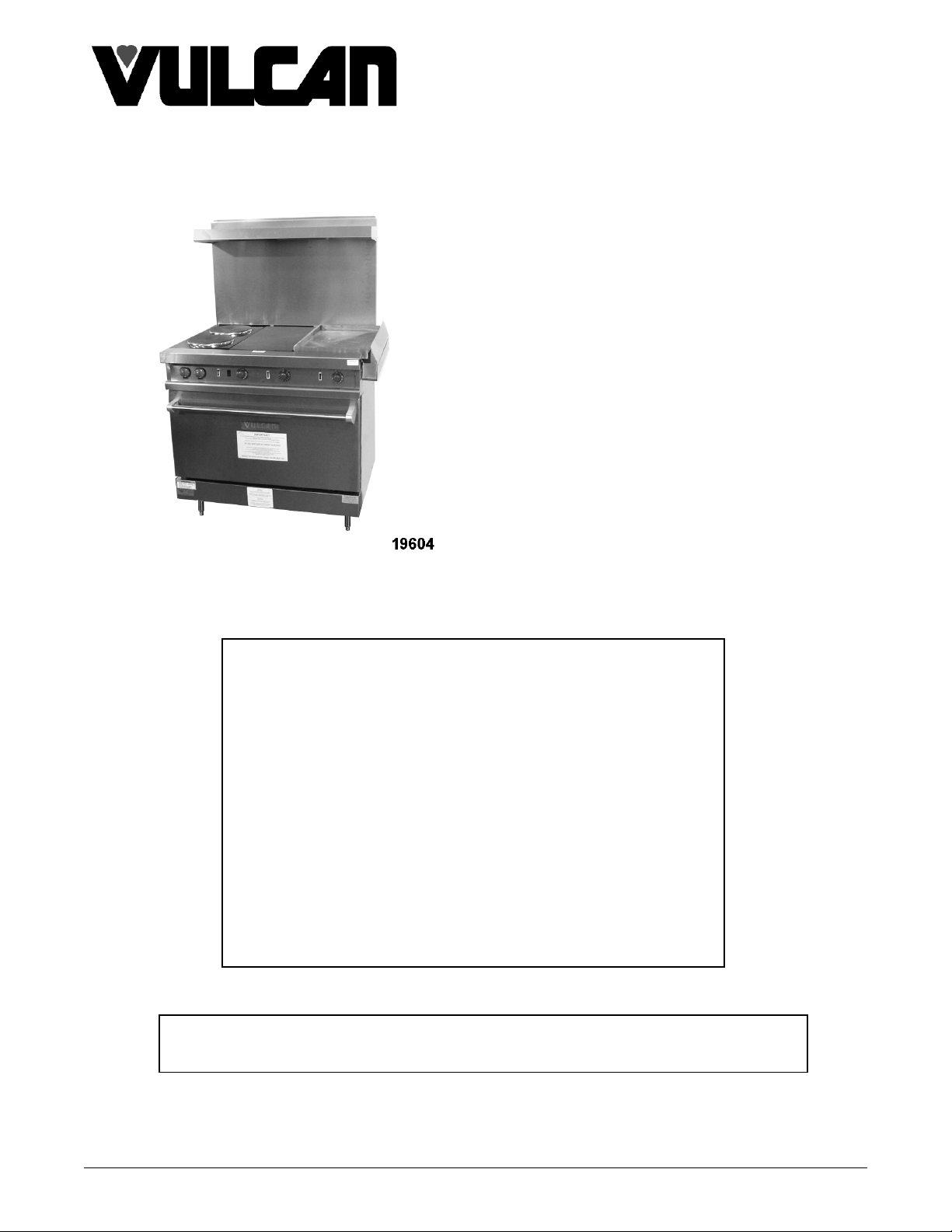
ELECTRIC RESTAURANT
RANGES
E36LC SERIES
E36SLC MODEL SHOWN
- NOTICE This Manual is prepared for the use of trained Vulcan Service
Technicians and should not be used by those not properly qualified.
If you have attended a Vulcan Service School for this product, you
may be qualified to perform all the procedures described in this
manual.
This manual is not intended to be all encompassing. If you have not
attended a Vulcan Service School for this product, you should read,
in its entirety, the repair procedure you wish to perform to
determine if you have the necessary tools, instruments and skills
required to perform the procedure. Procedures for which you do not
have the necessary tools, instruments and skills should be
performed by a trained Vulcan Service Technician.
ML-136624
Reproduction or other use of this Manual, without the express
written consent of Vulcan, is prohibited.
For additional information on Vulcan-Hart Company or to locate an authorized parts
and service provider in your area, visit our website at www.vulcanhart.com.
A product of VULCAN-HART Louisville, KY 40201-0696
Form 25297 (July 2008)
Page 2

E36LC SERIES ELECTRIC RESTAURANT RANGES
TABLE OF CONTENTS
GENERAL ................................................................................3
Introduction ............................................................................ 3
Installation ............................................................................ 3
Operation ............................................................................. 3
Cleaning .............................................................................. 3
Tools................................................................................. 3
Specifications .......................................................................... 3
REMOVAL AND REPLACEMENT OF PARTS .................................................... 4
Covers and Panels ...................................................................... 4
Range Tops ........................................................................... 4
Blower Wheel .......................................................................... 5
Blower Motor .......................................................................... 6
Door ................................................................................. 6
Door Mechanism Components ............................................................. 7
Door Switch ........................................................................... 8
Oven Heating Element ................................................................... 8
French Plate ........................................................................... 9
Hot Top.............................................................................. 10
Griddle Heating Element ................................................................ 11
Oven Thermostat ...................................................................... 12
Griddle and Hot Top Thermostats ......................................................... 13
Infinite Switch ......................................................................... 14
Rocker Switch......................................................................... 14
Indicator Lights ........................................................................ 15
Motor Contactor (480V Only) ............................................................. 15
SERVICE PROCEDURES AND ADJUSTMENTS................................................. 16
Oven Thermostat Calibration ............................................................. 16
Griddle Thermostat Calibration............................................................ 17
Hot Top Thermostat Calibration ........................................................... 17
3 Heat Switch Test (480V) ............................................................... 18
Infinite Switch Test (208, 240V) ........................................................... 18
Door Adjustment....................................................................... 18
Heating Element Test ................................................................... 19
ELECTRICAL OPERATION .................................................................. 20
Component Function ................................................................... 20
Oven Sequence of Operation ............................................................. 21
Wiring Diagrams ....................................................................... 22
TROUBLESHOOTING ...................................................................... 28
© VULCAN 2008
F25297 (July 2008) Page 2 of 28
Page 3
E36LC SERIES ELECTRIC RESTAURANT RANGES - GENERAL
GENERAL
INTRODUCTION
This manual is for the Vulcan Restaurant Series
Electric Range equipped with convection oven.
Procedures in this manual will apply to all models
unless specified. Pictures and illustrations will be of
model E36SLC unless otherwise noted.
All of the information, illustrations and specifications
contained in this manual are based on the latest
product information available at the time of printing.
INSTALLATION
Refer to the Instruction Manual for detailed
installation instructions.
OPERATION
Refer to the Instruction Manual for specific operating
instructions.
SPECIFICATIONS
CLEANING
Refer to the Instruction Manual for specific cleaning
instructions.
TOOLS
Standard
• Standard set of hand tools.
• VOM with A.C. current tester (Any quality VOM
with a sensitivity of at least 20,000 ohms per
volt can be used).
Special
• Temperature tester (thermocouple type) with
surface mount probe.
• Clamp on amp meter.
• Wheel puller, for blower wheel removal.
• Sealant, for thermostat calibration screw.
Model
No.
E36LC
E36SLC
E36FLC
E36XLC
AVAILABLE VOLTAGES - 208 OR 240 VOLT - 1 OR 3-PHASE, 480 VOLT - 3-PHASE
Nominal AMPS Per Line Wire
3-Phase
1-Phase
208V 240V 480V
X Y Z X Y Z X Y Z 208V 240V 480V
38.3 50.0 54.9 33.2 43.3 47.6 16.5 21.6 23.7 82.6 71.6 N/A
38.3 47.5 52.4 33.2 41.1 45.4 16.5 20.8 22.6 79.7 69.1 N/A
38.3 45.0 49.9 33.2 39.0 43.3 16.5 19.7 21.5 76.9 66.6 N/A
35.8 42.5 49.9 31.0 36.8 43.3 N/A N/A N/A 74.0 64.1 N/A
F25297 (July 2008)Page 3 of 28
Page 4
E36LC SERIES ELECTRIC RESTAURANT RANGES - REMOVAL AND REPLACEMENT OF PARTS
REMOVAL AND REPLACEMENT OF PARTS
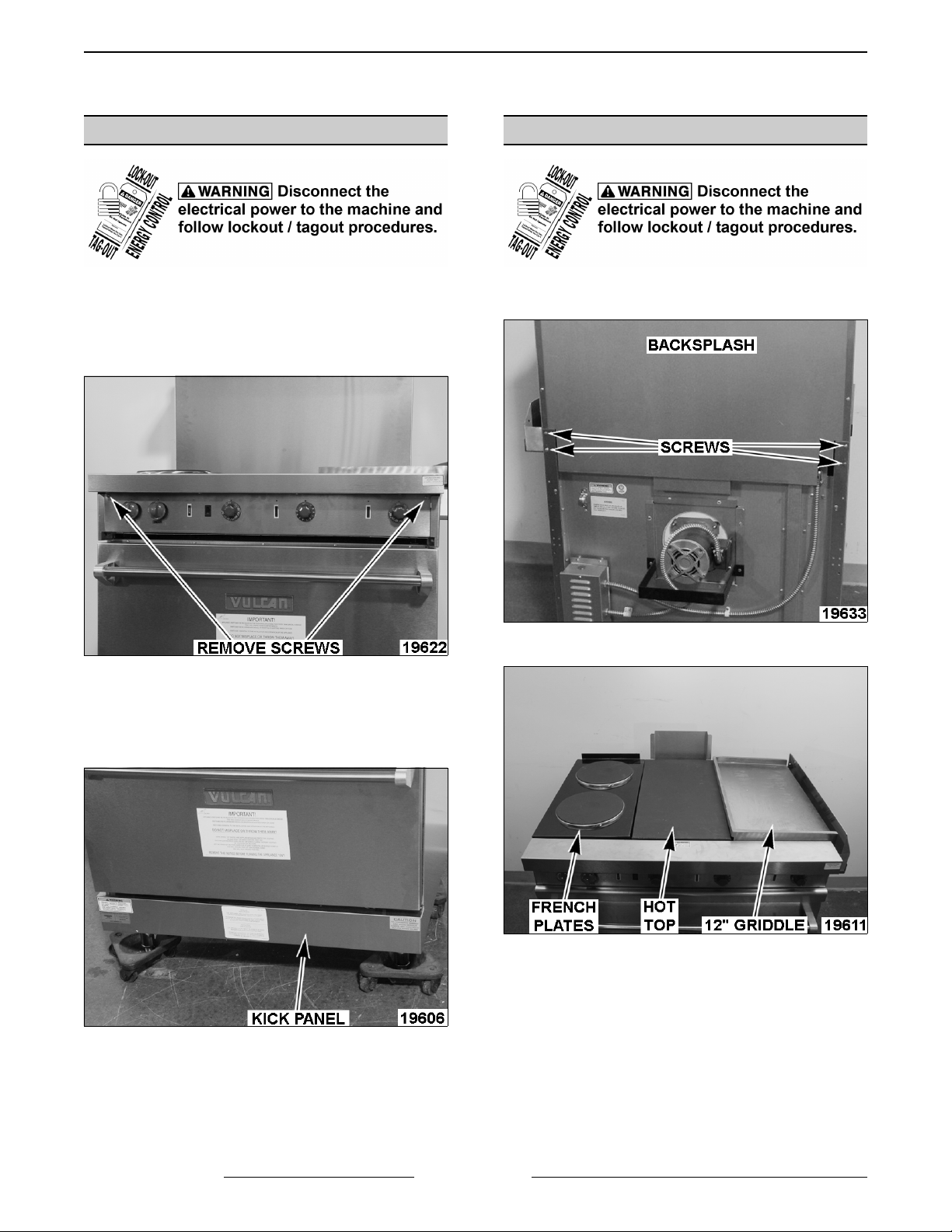
COVERS AND PANELS
Control Panel
1. Pull out or remove crumb tray.
2. Remove screws in top corners of control panel.
NOTE: Control panel is hinged and will open down.
RANGE TOPS
1. Remove screws securing backsplash to frame.
3. Reverse procedure to install.
Kick Panel
1. Open kick panel by lifting, pulling out and
rotating down.
2. Apply outward pressure on one of the ends to
remove.
3. Reverse procedure to install.
2. Lift off backsplash.
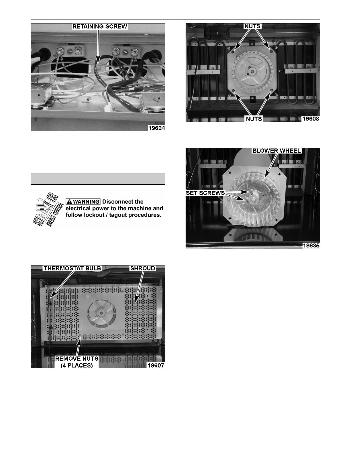
3. Open control panel as outlined under COVERS
AND PANELS.
4. Remove retaining screw securing range top
mounting bracket.
F25297 (July 2008) Page 4 of 28
Page 5
E36LC SERIES ELECTRIC RESTAURANT RANGES - REMOVAL AND REPLACEMENT OF PARTS
4. Pull blower into oven cavity.
5. Lift the range top being removed.
6. Disconnect the electrical connections.
7. Reverse procedure to install.
8. Check range for proper operation.
5. Remove two set scews from blower wheel hub.
BLOWER WHEEL
1. Remove oven racks.
2. Remove thermostat bulb from heating element
shroud; remove nuts and shroud.
3. Remove four nuts securing blower motor to
mounting bolts.
6. Remove blower wheel.
NOTE: A wheel puller may be necessary to remove
blower wheel from motor shaft.
7. Reverse procedure to install.
8. Check range for proper operation.
F25297 (July 2008)Page 5 of 28
Page 6
E36LC SERIES ELECTRIC RESTAURANT RANGES - REMOVAL AND REPLACEMENT OF PARTS
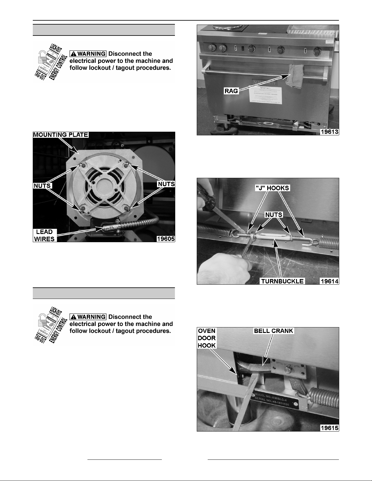
BLOWER MOTOR
1. Remove blower wheel as outlined under
BLOWER WHEEL.
2. Remove nuts securing mounting plate to motor.
3. Loosen nuts while holding "J" hooks from
rotating.
NOTE: One nut will be right hand threaded and the
other will be left hand threaded.
3. Remove mounting plate from motor.
4. Disconnect lead wires from motor.
5. Reverse procedure to install.
6. Check range for proper operation.
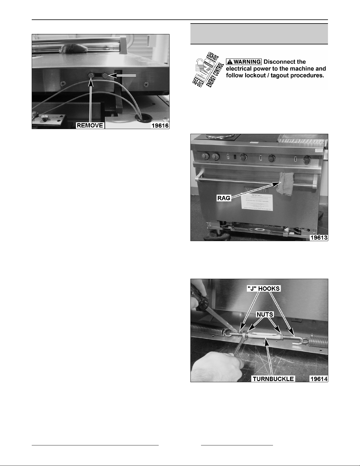
DOOR
Removal
1. Remove kick panel as outlined under COVERS
AND PANELS.
2. Pinch a rag in the door to prevent the door from
falling open during procedure.
4. Rotate turnbuckle to relieve most of the spring
tension.
5. Pry up left bell crank and remove oven door
hook.
6. Repeat with right bell crank.
F25297 (July 2008) Page 6 of 28
Page 7
E36LC SERIES ELECTRIC RESTAURANT RANGES - REMOVAL AND REPLACEMENT OF PARTS
7. Remove inside door bolts.
8. Loosen outside door screws, then slide to inside
of door slot to disengage pins from door
mounts.
9. Open door partly and remove.
Installation
1. Reverse removal procedure to install.
NOTE: Make sure that pins inside door engage
holes in door mounts.
DOOR MECHANISM
COMPONENTS
1. Remove kick panel as outlined under COVERS
AND PANELS.
2. Pinch a rag in the door to prevent the door from
falling open during procedure.
NOTE: Red oven door hook goes on the right side
and blue hook on the left.
2. Rotate turnbuckle to tension springs until door
closes on its own when held open 5 inches.
Door should bounce once or not at all.
3. Check range for proper operation.
3. Loosen nuts while holding "J" hooks from
rotating.
NOTE: One nut will be right hand threaded and the
other will be left hand threaded.
4. Rotate turnbuckle to relieve most of the spring
tension.
5. Remove springs, turnbuckle assembly, and
door hooks.
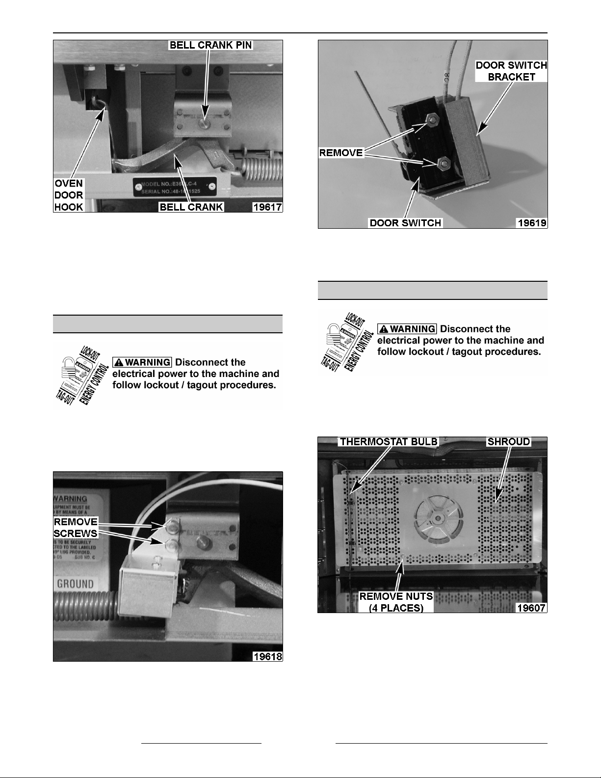
6. Remove cotter pins from bell crank pins (behind
bracket).
F25297 (July 2008)Page 7 of 28
Page 8
E36LC SERIES ELECTRIC RESTAURANT RANGES - REMOVAL AND REPLACEMENT OF PARTS
7. Remove bell crank pins and bell cranks.
8. Reverse procedure to install.
9. Check range for proper operation.
NOTE: Tension springs until door closes on its own
when held open 5 inches. Door should bounce once
or not at all.
DOOR SWITCH
1. Open kick panel as outlined under COVERS
AND PANELS.
2. Remove door switch bracket mounting screws.
4. Disconnect electrical wiring from switch.
5. Reverse procedure to install.
6. Check range for proper operation.
OVEN HEATING ELEMENT
1. Remove oven racks.
2. Remove thermostat bulb from heating element
shroud.
3. Remove heating element shroud.
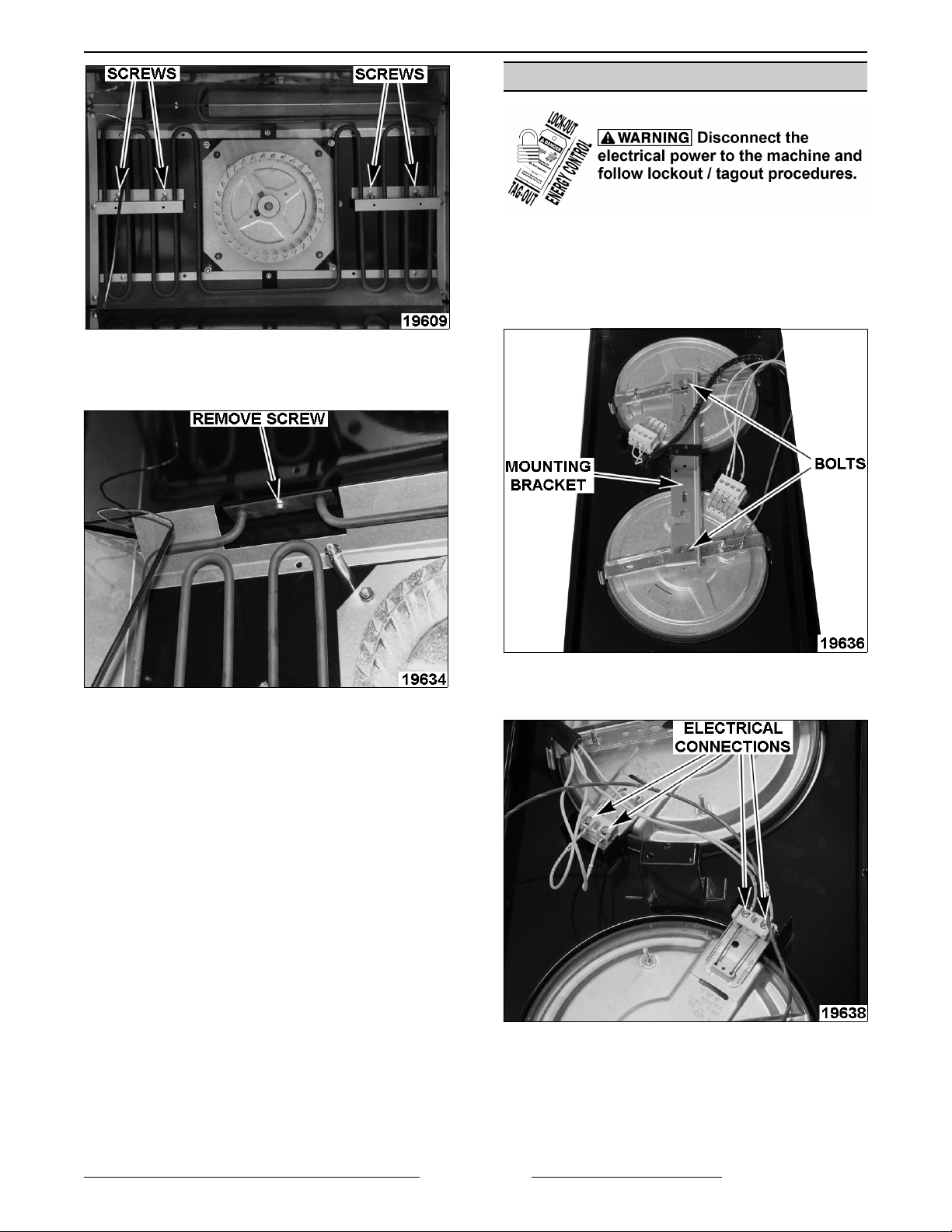
4. Remove screws mounting heating element
3. Remove nuts securing door switch to door
switch bracket.
F25297 (July 2008) Page 8 of 28
brackets to oven back wall.
Page 9
E36LC SERIES ELECTRIC RESTAURANT RANGES - REMOVAL AND REPLACEMENT OF PARTS
FRENCH PLATE
1. Remove french plates as outlined under
RANGE TOPS.
2. Remove bolts holding mounting bracket to the
french plate assemblies.
5. Remove screw securing heating element and
pull element out to expose lead wire
connections.
6. Disconnect the lead wires.
7. Reverse procedure to install.
8. Check range for proper operation.
3. Remove electrical connections noting their
location.
4. Remove the nut, spring washer, and locking
bracket.
NOTE: Support the french plate from underneath.
F25297 (July 2008)Page 9 of 28
Page 10

E36LC SERIES ELECTRIC RESTAURANT RANGES - REMOVAL AND REPLACEMENT OF PARTS
5. Remove french plate.
6. Reverse procedure to install.
7. Check range for proper operation.
5. Bend hooks in slightly, then remove electrical
connections.
HOT TOP
1. Remove hot top as outlined under RANGE
TOPS.
2. Remove nuts holding thermostat bulb clamp to
the plate assembly.
3. Remove thermostat bulb clamp and thermostat
bulb from hot top.
4. Remove inside screws from electrical
connections.
6. Remove hot top.
7. Reverse procedure to install.
8. Check range for proper operation.
F25297 (July 2008) Page 10 of 28
Page 11

E36LC SERIES ELECTRIC RESTAURANT RANGES - REMOVAL AND REPLACEMENT OF PARTS
GRIDDLE HEATING ELEMENT
NOTE: 12" griddle shown.
1. Remove griddle as outlined under RANGE
TOPS.
2. Remove nuts and washers to disconnect
element wiring.
6. Remove nuts securing griddle element holding
clamps.
3. Remove nuts securing griddle base cover.
4. Remove griddle base cover.
5. Loosen screws to remove thermostat bulb and
clamp.
7. Remove holding clamps.
8. Remove griddle element.
9. Reverse procedure to install.
10. Check range for proper operation.
F25297 (July 2008)Page 11 of 28
Page 12

E36LC SERIES ELECTRIC RESTAURANT RANGES - REMOVAL AND REPLACEMENT OF PARTS
OVEN THERMOSTAT
1. Remove thermostat knob.
2. Remove thermostat mounting screws.
6. Remove left range top as outlined under
RANGE TOPS.
7. Pull capillary tube and thermostat bulb through
roof of oven cavity.
3. Open the control panel as outlined under
COVERS AND PANELS.
4. Disconnect the lead wires from the thermostat
noting their locations.
5. Remove thermostat bulb from heating element
shroud.
8. Remove thermostat.
NOTE: Do not kink capillary tube.
9. Reverse procedure to install.
NOTE: Route capillary tube so it does not contact
any electrical component.
10. Perform OVEN THERMOSTAT CALIBRATION
as outlined under SERVICE PROCEDURES
AND ADJUSTMENTS.
11. Check range for proper operation.
F25297 (July 2008) Page 12 of 28
Page 13

E36LC SERIES ELECTRIC RESTAURANT RANGES - REMOVAL AND REPLACEMENT OF PARTS
GRIDDLE AND HOT TOP
THERMOSTATS
1. Remove thermostat knob.
2. Remove thermostat mounting screws.
HOT TOP SHOWN
NOTE: See GRIDDLE HEATING ELEMENT to
access griddle thermostat bulb.
7. Remove thermostat bulb from clamp.
8. Remove thermostat.
NOTE: Do not kink capillary tube.
3. Open the control panel as outlined under
COVERS AND PANELS.
4. Disconnect the lead wires from the thermostat
noting their locations.
9. Reverse procedure to install.
NOTE: Route capillary tube so it does not contact
any electrical component.
10. Perform HOT TOP or GRIDDLE THERMOSTAT
CALIBRATION as outlined under SERVICE
PROCEDURES AND ADJUSTMENTS.
11. Check range for proper operation.
5. Access underside of range top as outlined
under RANGE TOPS.
6. Remove fasteners from thermostat bulb clamp.
F25297 (July 2008)Page 13 of 28
Page 14

E36LC SERIES ELECTRIC RESTAURANT RANGES - REMOVAL AND REPLACEMENT OF PARTS
INFINITE SWITCH
1. Pull off infinite switch knob.
2. Remove washer nut from applicable infinite
switch stem.
ROCKER SWITCH
1. Open control panel as outlined under COVERS
AND PANELS.
2. Disconnect rocker switch electrical connections
noting their locations.
3. Open control panel as outlined under COVERS
AND PANELS.
4. Remove infinite switch wire connections from
switch being replaced. Note wire locations.
5. Remove infinite switch.
6. Reverse procedure to install.
3. Squeeze in on the tabs at the ends of the rocker
switch and push through the control panel.
4. Reverse procedure to install.
5. Check range for proper operation.
7. Check range for proper operation.
F25297 (July 2008) Page 14 of 28
Page 15

E36LC SERIES ELECTRIC RESTAURANT RANGES - REMOVAL AND REPLACEMENT OF PARTS
INDICATOR LIGHTS
1. Open control panel as outlined under COVERS
AND PANELS.
2. Disconnect indicator light electrical connections
noting their locations.
MOTOR CONTACTOR
(480V ONLY)
1. Remove contactor box cover.
2. Disconnect all electrical connections to the
contactor noting their locations.
3. Loosen contactor screws.
3. Squeeze in on the tabs at the ends of the
indicator light and push through the control
panel.
4. Reverse procedure to install.
5. Check range for proper operation.
4. Lift and remove contactor.
5. Reverse procedure to install.
6. Check range for proper operation.
F25297 (July 2008)Page 15 of 28
Page 16

E36LC SERIES ELECTRIC RESTAURANT RANGES - SERVICE PROCEDURES AND ADJUSTMENTS
SERVICE PROCEDURES AND ADJUSTMENTS
Certain procedures in this section require electrical test or measurements while power is
applied to the machine. Exercise extreme caution at all times. If test points are not easily accessible,
disconnect power and follow lockout / tagout procedures, attach test equipment and reapply power to
test.
OVEN THERMOSTAT
CALIBRATION
1. Place a temperature tester probe in the
geometric center of the oven.
2. Set the thermostat to 350°F.
3. Allow the thermostat to cycle three times.
4. Note the tester reading when the oven indicator
light turns ON and OFF.
NOTE: If the difference between the ON and OFF
temperature is greater than 25°F, replace the
thermostat.
5. Add these two temperatures together, then
divide the sum by 2 to obtain an average
temperature.
A. If the average temperature is within 10°F of
the set temperature, the thermostat is
calibrated.
B. If the average temperature is not within
10°F of the set temperature:
1) Remove thermostat knob.
2) Insert a flathead screwdriver into
thermostat dial stem until it reaches
the calibration screw.
3) Turn adjustment screw CW to
increase and CCW to decrease
temperature.
NOTE: A 1/4 turn equals 35°F change.
6. Replace knob and repeat steps 3 to 5 until
average temperature is within 10°F of set
temperature.
7. Reseal adjustment screw to prevent movement.
8. If thermostat cannot be calibrated, replace
thermostat as outlined under OVEN
THERMOSTAT in REMOVAL AND
REPLACEMENT OF PARTS.
F25297 (July 2008) Page 16 of 28
Page 17

E36LC SERIES ELECTRIC RESTAURANT RANGES - SERVICE PROCEDURES AND ADJUSTMENTS
GRIDDLE THERMOSTAT
CALIBRATION
1. Clean the temperature test site, then place
temperature tester surface mount probe there.
See table for proper testing locations according
to griddle size.
NOTE: This procedure will need to be performed for
each testing location on the 24" and 36" griddles.
Griddle Size Distance(s)
From Left Edge of Griddle
12"
24"
36"
1. All readings taken 12" from front of griddle.
2. Set the thermostat to a temperature above
300°F.
3. Allow the thermostat to cycle three times.
4. Note the tester reading when the indicator light
turns ON and OFF.
NOTE: If the difference between the ON and OFF
temperatures is greater than 25°F, replace the
thermostat.
5. Add these two temperatures together, then
divide the sum by 2 to obtain an average
temperature.
A. If the average temperature is within 10°F of
the set temperature, the thermostat is
calibrated.
B. If the average temperature is not within
10°F of the set temperature:
1) Remove thermostat knob.
2) Insert a flathead screwdriver into
thermostat dial stem until it reaches
the calibration screw.
6"
6", 18"
6", 18", 30"
3) Turn adjustment screw CW to
increase and CCW to decrease
temperature.
NOTE: A 1/4 turn equals 35°F change.
6. Replace knob and repeat steps 3 and 5 until
average temperature is within 10°F of set
temperature.
7. Reseal adjustment screw to prevent movement.
8. If thermostat cannot be calibrated, replace
thermostat as outlined under GRIDDLE & HOT
TOP THERMOSTATS in REMOVAL AND
REPLACEMENT OF PARTS.
HOT TOP THERMOSTAT
CALIBRATION
1. Set the control to position 3 (approx. 460°F).
2. Allow the thermostat to cycle three times.
3. When the hot top indicator light goes out, place
the temperature tester surface mount probe
directly in the middle of the hot top.
4. Note the tester reading when the indicator light
turns ON and OFF.
NOTE: If the difference between the ON and OFF
temperatures is greater than 25°F, replace the
thermostat.
5. Add these two temperatures together, then
divide the sum by 2 to obtain an average
temperature.
A. If the average temperature is within 10°F of
the set temperature, the thermostat is
calibrated.
B. If the average temperature is not within
10°F of the set temperature:
1) Remove thermostat knob.
2) Insert a flathead screwdriver into
thermostat dial stem until it reaches
the calibration screw.
F25297 (July 2008)Page 17 of 28
Page 18

E36LC SERIES ELECTRIC RESTAURANT RANGES - SERVICE PROCEDURES AND ADJUSTMENTS
3) Turn adjustment screw CW to
increase and CCW to decrease
temperature.
NOTE: A 1/4 turn equals 35°F change.
6. Replace knob and repeat steps 4 and 5 until
average temperature is within 10°F of set
temperature.
7. Reseal adjustment screw to prevent movement.
8. If thermostat cannot be calibrated, replace
thermostat as outlined under GRIDDLE & HOT
TOP THERMOSTATS in REMOVAL AND
REPLACEMENT OF PARTS.
3 HEAT SWITCH TEST (480V)
1. Open the control panel as outlined under
COVERS AND PANELS in REMOVAL AND
REPLACEMENT OF PARTS.
2. Check input voltage at L3 and L2.
NOTE: See AI 2207 in WIRING DIAGRAMS.
3. Check for correct output voltage at output pins
for all positions of the switch.
DOOR ADJUSTMENT
NOTE: Door is in adjustment when it closes on its
own when held open 5 inches and comes to rest
after 1 or 0 bounces.
1. Remove the kick panel as outlined under
COVERS AND PANELS in REMOVAL AND
REPLACEMENT OF PARTS.
2. Loosen nuts while holding "J" hooks from
rotating.
NOTE: One nut will be right hand threaded and the
other will be left hand threaded.
Position
High 1 & 3 2
Med 1 2
Low 1 3
L3 Input-Output
at Pin(s)
L2 Input-Output
at Pin(s)
INFINITE SWITCH TEST
(208, 240V)
1. Open the control panel as outlined under
COVERS AND PANELS in REMOVAL AND
REPLACEMENT OF PARTS.
2. Connect a voltmeter (set on 300VAC range) to
the output terminals H1 and H2.
3. Compare the percentage of ON time to OFF
time.
NOTE: ±7.5% tolerance allowable.
Dial
Setting
Hi 100 ALL 0
Med. 48 15 15
Low 37 8 14
Med. Low 28 7 24
Very Low 7 3 33
% on
Time
SecondsonSeconds
off
3. Rotate turnbuckle to either increase or decrease
spring tension.
NOTE: "J" hooks cannot rotate while rotating
turnbuckle in order to adjust tension.
4. Once desired spring tension is acquired, tighten
nuts.
5. Install kick panel.
F25297 (July 2008) Page 18 of 28
Page 19

E36LC SERIES ELECTRIC RESTAURANT RANGES - SERVICE PROCEDURES AND ADJUSTMENTS
HEATING ELEMENT TEST
1. Turn power ON and set temperature control to
the highest setting.
2. Measure the voltage at the heating element
terminals and verify it against the data plate
voltage.
A. If voltage is incorrect
problem. If voltage is correct
draw (amps) through the heating element
lead wires.
NOTE: This method is preferred over a resistance
check when a clamp on type amp meter is available.
1) If current draw is correct then heating
element is functioning properly. See
table below for proper values.
2) If current draw is not
power switch OFF and disconnect
the electrical supply to the oven.
a. Replace heating element then
proceed to step 3.
, find the source of the
, check current
correct, turn the
B. If unable to check current draw, a
resistance check may
malfunctioning element.
1) Disconnect electrical supply.
2) Remove lead wires from the heating
element and check resistance (ohms).
See table below for proper values.
3. Check for proper operation.
indicate a
Voltage Element KW per Element AMPS per Element Lead OHMS per Element
5 24.03 8.65
5 24.03 8.65
2 9.61 21.63
3.4 16.34 12.73
5 20.83 11.52
5 20.83 11.52
2 8.33 28.80
3.4 14.16 16.94
5 10.41 17.28
5 10.41 17.28
2 4.16 43.20
3.4 7.08 25.41
208
240
480
NOTES:
Oven
Hot Top
French Plate
Griddle
Oven
Hot Top
French Plate
Griddle
Oven
Hot Top
French Plate
Griddle
1. Values in the table are nominal. Tolerance is +5/-10%.
2. Voltage values are @ 60HZ.
3. Resistance values (ohms) are @ 77° F.
F25297 (July 2008)Page 19 of 28
Page 20

E36LC SERIES ELECTRIC RESTAURANT RANGES - ELECTRICAL OPERATION
ELECTRICAL OPERATION
COMPONENT FUNCTION
Thermostat ................ Regulates temperature of oven cavity, griddle, and hot top.
3 Heat Switch .............. Controls how power is applied to oven heating element assemblies and to the
hot plates on 480V units.
Heating Elements ........... Heats oven cavity and range tops.
Infinite Switch .............. Controls power to hot plate heaters, full power for a specified amount of time
per position of the switch.
Contactors (2) .............. Controls power to convection blower motor. Second contactor controls power
to oven elements. (480V units only)
Door Switch ............... Prevents convection oven from operating with the door open.
Rocker Switch .............. Controls power from contactor to convection oven switch.
Transformer ............... Steps 480V down to 240V.
Fuses (2) .................. Protect convection oven control circuit on 208V and 240V units. (15 amp)
Indicator Light.............. Lights when power is being applied to heating elements.
F25297 (July 2008) Page 20 of 28
Page 21

E36LC SERIES ELECTRIC RESTAURANT RANGES - ELECTRICAL OPERATION
OVEN SEQUENCE OF
OPERATION
208/240V
1. Conditions
A. Unit connected to supply voltage.
B. Thermostat OFF.
C. Rocker switch OFF.
D. Door switch closed.
E. Oven at room temperature.
2. Rocker switch turned ON.
A. Blower motor runs.
3. Thermostat set to desired temperature.
A. Indicator light lights.
B. Power is supplied to heaters.
4. Oven reaches desired temperature.
A. Power is removed from the heaters and
indicator light.
5. Oven temperature drops below set temperature.
A. Steps 4 and 5 cycle until the thermostat or
rocker switch is turned OFF or power is
removed from the oven.
480V
1. Conditions
A. Unit connected to supply voltage.
B. Thermostat OFF.
C. Rocker switch OFF.
D. Door switch closed.
E. Oven at room temperature.
2. Rocker switch turned ON.
A. Motor contactor is energized and blower
motor runs.
3. Thermostat set to desired temperature.
A. Indicator light lights.
B. Heater contactor is energized and power is
supplied to heaters.
4. Oven reaches desired temperature.
A. Power removed from heater contactor,
power is removed from the heaters and
indicator light.
5. Oven temperature drops below set temperature.
A. Thermostat contacts close and steps 4 and
5 cycle until the thermostat or rocker switch
is turned OFF or power is removed from
the oven.
F25297 (July 2008)Page 21 of 28
Page 22

E36LC SERIES ELECTRIC RESTAURANT RANGES - ELECTRICAL OPERATION
WIRING DIAGRAMS
E36LC (208, 240V) Wiring Diagram
F25297 (July 2008) Page 22 of 28
Page 23

E36LC SERIES ELECTRIC RESTAURANT RANGES - ELECTRICAL OPERATION
F25297 (July 2008)Page 23 of 28
Page 24

E36LC SERIES ELECTRIC RESTAURANT RANGES - ELECTRICAL OPERATION
E36LC (480V) Wiring Diagram
F25297 (July 2008) Page 24 of 28
Page 25

E36LC SERIES ELECTRIC RESTAURANT RANGES - ELECTRICAL OPERATION
F25297 (July 2008)Page 25 of 28
Page 26

E36LC SERIES ELECTRIC RESTAURANT RANGES - ELECTRICAL OPERATION
208V & 240V Range Top Wiring Diagrams
F25297 (July 2008) Page 26 of 28
Page 27

E36LC SERIES ELECTRIC RESTAURANT RANGES - ELECTRICAL OPERATION
480V Range Top Wiring Diagrams
F25297 (July 2008)Page 27 of 28
Page 28

E36LC SERIES ELECTRIC RESTAURANT RANGES - TROUBLESHOOTING
TROUBLESHOOTING
Oven
SYMPTOM POSSIBLE CAUSES
No heat, blower inoperative. 1. Main breaker open.
2. Thermostat malfunction.
3. Rocker switch open.
4. Contactors malfunctioning (480V).
5. Oven door switch open.
6. Heaters inoperative.
7. Transformer malfunction (480V).
No heat, blower operative. 1. Heating element contactor malfunction (480V).
2. Heaters inoperative.
Cooking problems. 1. Consult Instruction Manual.
Oven temperature not at set point. 1. Thermostat not calibrated.
2. Thermostat malfunction.
Range Tops
SYMPTOM POSSIBLE CAUSES
Tops do not heat. 1. Main breaker open.
2. Thermostat malfunction (griddle, hot top).
3. 3 heat switch malfunction (french plates 480V).
4. Infinite switch inoperative (french plates 208-240V).
5. Top inoperative.
Hot top or griddle thermostat cycles at a different
temperature than the set temperature.
Cooking problems. 1. Consult Instruction Manual.
Hot top or griddle heats beyond set temperature. 1. Thermostat not calibrated.
1. Thermostat needs calibrated.
2. Thermostat inoperative.
3. Thermostat bulb positioned incorrectly.
2. Thermostat malfunction.
F25297 (July 2008) Printed in U.S.A.
 Loading...