

Page 1
SERVICE MANUAL
C24GA AND C24DA SERIES
CONVECTION STEAMER
C24GA6 ML-136021
ML-136056
ML-136085
C24GA10 ML-136022
ML-136057
ML-136085
C24DA6 ML-152022
C24DA10 ML-152023
- NOTICE -
This Manual is prepared for the use of trained Hobart Service
Technicians and should not be used by those not properly
qualified.
This manual is not intended to be all encompassing. If you have
not attended a Hobart Service School for this product, you should
read, in its entirety, the repair procedure you wish to perform to
determine if you have the necessary tools, instruments and skills
required to perform the procedure. Procedures for which you do
not have the necessary tools, instruments and skills should be
performed by a trained Hobart Service Technician.
The reproduction, transfer, sale or other use of this manual,
without the express written consent of Hobart, is prohibited.
This manual has been provided to you by ITW Food Equipment
Group LLC ("ITW FEG") without charge and remains the property
of ITW FEG, and by accepting this manual you agree that you will
return it to ITW FEG promptly upon its request for such return at
any time in the future.
A product of Vulcan-Hart 3600 North Point Blvd Baltimore, MD 21222
F35425 Rev. E (0119)
Page 2

C24GA AND C24DA SERIES CONVECTION STEAMER
TABLE OF CONTENTS
SERVICE UPDATES ....................................................................................... 4
SERVICE UPDATES - C24GA .......................................................................... 4
TIS DOCUMENT LIST - C24GA SERIES ................................................................ 4
GENERAL .................................................................................................. 7
INSTALLATION, OPERATION AND CLEANING ......................................................... 7
INTRODUCTION ....................................................................................... 7
GENERAL .......................................................................................... 7
STEAM COOKING ................................................................................. 7
WATER QUALITY STATEMENT ........................................................................ 7
SPECIFICATIONS ...................................................................................... 8
ELECTRIC ......................................................................................... 8
GAS PRESSURES ................................................................................. 8
TOOLS ................................................................................................. 8
REMOVAL AND REPLACEMENT OF PARTS .............................................................. 10
COVERS AND PANELS ............................................................................... 10
COOKING COMPARTMENT SIDE PANELS ....................................................... 10
COOKING COMPARTMENT FLUE WRAP ......................................................... 10
CABINET BASE RIGHT SIDE PANEL .............................................................. 10
CABINET BASE LEFT SIDE PANEL ............................................................... 10
CABINET BASE FRONT PANEL ................................................................... 11
CABINET BASE REAR PANEL .................................................................... 11
COMPARTMENT CONTROLS-OLD ................................................................... 11
COOKING COMPARTMENT DOOR ................................................................... 12
MAIN BURNER ....................................................................................... 15
GAS COMBINATION CONTROL VALVE ............................................................... 16
GENERATOR ASSEMBLY ............................................................................ 17
FILL AND COLD WATER SOLENOID VALVES ........................................................ 19
PILOT/SPARK PROBE FLAME SENSOR (ONLY UNITS WITH ADJUSTABLE PILOT) .................. 20
BLOWER CONTROL RELAY (K3) ..................................................................... 21
SERVICE PROCEDURES AND ADJUSTMENTS ........................................................... 22
BLOWER AIR PRESSURE ADJUSTMENT (ONLY UNITS WITH ADJUSTABLE PILOT) ................. 22
SOLARONICS BURNER ADJUSTMENT (STARTING AT SERIAL NUMBER 463024850) ................ 24
AIR PRESSURE SWITCH ADJUSTMENT (ONLY UNITS WITH ADJUSTABLE PILOT) .................. 26
PILOT BURNER ADJUSTMENT (ONLY UNITS WITH ADJUSTABLE PILOT) ........................... 27
AUTOMATIC IGNITION SYSTEMS .................................................................... 34
IGNITION TEST ....................................................................................... 37
MANIFOLD PRESSURE ADJUSTMENT (ONLY UNITS WITH ADJUSTABLE PILOT) ................... 37
COOKING COMPARTMENT .......................................................................... 39
DOOR ................................................................................................ 39
LATCH ADJUSTMENT ............................................................................ 39
STRIKER ADJUSTMENT .......................................................................... 40
DELIME GENERATOR ................................................................................ 40
COOKING CYCLE TEST .............................................................................. 41
GENERAL ........................................................................................ 41
PROBE INSPECTION ................................................................................. 42
MAINTANENCE CHECKS ............................................................................. 42
ELECTRICAL OPERATION ................................................................................ 44
WATER LEVEL CONTROLS .......................................................................... 44
LOW LEVEL CUT-OFF AND DIFFERENTIAL CONTROL ........................................... 44
SEQUENCE OF OPERATION ......................................................................... 44
SOLARONICS BURNER SEQUENCE OF OPERATION ................................................ 47
COMPONENT FUNCTION - COMPARTMENT ......................................................... 49
COMPONENT FUNCTION - STEAM GENERATOR .................................................... 50
F35425 Rev. E (0119) Page 2 of 65
Page 3

C24GA AND C24DA SERIES CONVECTION STEAMER
COMPONENT LOCATION ............................................................................. 51
SCHEMATICS AND DIAGRAMS ....................................................................... 54
TROUBLESHOOTING ..................................................................................... 59
TROUBLESHOOTING (ADJUSTABLE PILOTS ONLY) ................................................. 59
GENERAL ........................................................................................ 59
WATER NOT BEING SUPPLIED TO GENERATOR ................................................ 59
PILOT OR MAIN BURNER WILL NOT LIGHT ...................................................... 59
DRAIN SOLENOID VALVE DOES NOT DRAIN .................................................... 59
WATER ACCUMULATING IN COMPARTMENT .................................................... 59
COOKING CYCLE CANNOT BE ACTIVATED ...................................................... 59
STEAMER ACHIEVES PRESSURE SLOWER THAN NORMAL .................................... 59
TROUBLESHOOTING SEQUENCE OF OPERATION .................................................. 60
TROUBLESHOOTING CHART ........................................................................ 61
LED DIAGNOSTIC FLASH CODES (SOLARONICS BURNER SYSTEM WITH
FENWAL IGNITION MODULE UNITS ONLY) ...................................................... 65
© VULCAN 2019
Page 3 of 65 F35425 Rev. E (0119)
Page 4
C24GA AND C24DA SERIES CONVECTION STEAMER - SERVICE UPDATES
SERVICE UPDATES
SERVICE UPDATES - C24GA
January, 2019
• Add swtich step to SOLARONICS BURNER ADJUSTMENT (STARTING AT SERIAL NUMBER
463024850).
December, 2018
• Add C24DA Schematic and Models to service manual.
November, 2018
• Added SOLARONICS BURNER ADJUSTMENT (STARTING AT SERIAL NUMBER 463024850).
• Added BLOWER CONTROL RELAY (K3).
• TROUBLESHOOTING CHART
• Added SOLARONICS BURNER SEQUENCE OF OPERATION.
• Miscellaneous updates per product support.
November, 2014
• This Service Manual was completely revised to include the Professional Model. This revsion was released in
November, 2014. No updates presently apply.
TIS DOCUMENT LIST - C24GA Series
SERVICE TAB
Document Title Document Type
C24GA Convection Steamer Service Manual Service Manual
#00-858726 Burner Assembly Replacement Service Kit Instructions (SKI)
C24GA 6 & 10 Gas Floor Steamers - Pressure Switch Not
Maintaining Setpoint
Substitute Ignition Module C24GA steamers Part No.
00-857207-00002
SERVICE TAB (Multimedia)
Document Title Document Type
All Stainless Steel with Automatic Timers & Manual
Boilers Direct Steam - ST. STL. LEG
Electric Boiler Owners Manual Instructions
Repair Flood-Damaged Food Equipment Misc
C24GA6 & C24GA10 Gas Convection Steamers I/O
Manual
C24GA6 & C24GA10 Nason Relay Instructions Service Instructions
Deliming Instructions C24GA6/10 Series Steamers Service Instructions
Fundamentals of Steam Service Instructions
Temporary Service Instructions (TSI)
Temporary Service Instructions (TSI)
Instructions
Operator
F35425 Rev. E (0119) Page 4 of 65
Page 5
C24GA AND C24DA SERIES CONVECTION STEAMER - SERVICE UPDATES
SERVICE TAB (Multimedia)
Fundamentals of Gas Service Instructions
Hobart Water Filter Replacement Cross Reference Sheet Service Instructions
Pilot & Burner Problems on Units Without Powered
Burners Service Information
ScaleStick Twin System, Part No. 01-234301-51200 Service Instructions
Water Level Pressure Switches Information Service Instructions
Rating Plate Locations on Current Vulcan-Hart/Wolf
Range Equipment
SB630 Gas Range Thermocouples Technical Service Bulletin (TSB)
SB760 Vulcan Steam Temporary Service Instruction /
Inspect All Warrick Water Level
SB780 Vulcan C24GA Series Steamers - Enhancements
& Additional Service
SB790 Vulcan C24GA - Elimination of Hold Thermostat Technical Service Bulletin (TSB)
SB800 Vulcan Steam Equipment - Enhanced Ignition
Modules
SB820 C24GA Series Steamers - Pilot Air Assembly
Change & Pressure Regulator
SB860 Atmospheric Steamer Door Switch Actuator Rod Technical Service Bulletin (TSB)
TSB 1374 Water Level Control Part No. 844069-1
Changes
TSB 1393 Steam Cooking Equipment - Prevention,
Detection and Treatment of Corrosion on Stainless Steel
TSB 1037A Hobart to Vulcan "Common" Model Cross
Reference List
TSB 1270 C24GA (Vulcan) - Elimination of Hold
Thermostat
TSB 1281 C24GA(Vulcan) Series Enhancements &
Additional Service Information
TSB 1298A Atmospheric Steamer Door Switch Actuator
Rod
TSB 1300B Vulcan Steam Equipment - Enhanced
Ignition Modules
TSB 1301 Onwatch Quicklook 72 for Gas Cooking
Equipment
TSB 1308 C24GA (Vulcan) Series Steamers - Pilot Air
Assembly Change and Pressure Regulator Addition
TSB 1339 Vulcan High Efficiency Gas Steamers - Burner
Noise
TSB 1360 C24GA Series Gas Steamers - Worm Gear
Hose Clamps Replacement with Constant Tension Hose
Clamps
TSB 1385 C24GA Series Gas Steamers - Universal
Generator Kit Part No. 857684-1
Service Instructions
Technical Service Bulletin (TSB)
Technical Service Bulletin (TSB)
Technical Service Bulletin (TSB)
Technical Service Bulletin (TSB)
Technical Service Bulletin (TSB)
Technical Service Bulletin (TSB)
Technical Service Bulletin (TSB)
Technical Service Bulletin (TSB)
Technical Service Bulletin (TSB)
Technical Service Bulletin (TSB)
Technical Service Bulletin (TSB)
Technical Service Bulletin (TSB)
Technical Service Bulletin (TSB)
Technical Service Bulletin (TSB)
Technical Service Bulletin (TSB)
Technical Service Bulletin (TSB)
Temporary Service Instructions (TSI)
Page 5 of 65 F35425 Rev. E (0119)
Page 6
C24GA AND C24DA SERIES CONVECTION STEAMER - SERVICE UPDATES
SERVICE TAB (Multimedia)
C24GA Series Gas Steamers - Blower Air Pressure
Adjustment Procedure Change
Hobart & Vulcan Steamers/Kettles with Warrick Water
Level Control Boards
Steamers - Main Transformer Primary Tap on Electric
Machines
Steamers Wire Insulation Pinched Under Screw Lug on
Terminal Block & Contractors
PARTS TAB
Document Title Document Type
Part Catalog for C24GA 6 & 10 Parts Catalog
Temporary Service Instructions (TSI)
Temporary Service Instructions (TSI)
Temporary Service Instructions (TSI)
Temporary Service Instructions (TSI)
F35425 Rev. E (0119) Page 6 of 65
Page 7
C24GA AND C24DA SERIES CONVECTION STEAMER - GENERAL
GENERAL
INSTALLATION, OPERATION AND
CLEANING
Refer to the F35423 - C24GA6/10 Series Gas
Convection Steamers Installation & Operation
Manual and F35439 -Deliming Instructions
C24GA6/10 Series Steamers for specific instructions.
INTRODUCTION
General
Procedures in this manual will apply to all models
unless specified. Pictures and illustrations can be of
any model unless the picture or illustration needs to
be model specific. All information and specifications
contained in this manual are based on the latest
product information available at the time of printing.
Steam Cooking
Convection steamers offer an efficient way to produce
many foods in either small portions or larger batches.
Convection steam cooking will steam cook fresh foods
or will steam defrost and cook frozen foods providing
the maximum color, flavor and nutritional value with
the least expenditure of energy and labor. The
atmospheric steaming compartment allows the
operator to open and close the door anytime during a
cooking cycle. The generator burner heating will shut
off when the door is opened then re-start when the
door is closed.
equipment will vary depending on the local water
conditions. Your water supply must be within the
general guidelines outlined in the chart below at all
times during use of this machine or service issues not
covered under warranty may result.
Water hardness should be treated by removing the
impurities (water softener with carbon block or
dechlorinator and/or in-line water treatment). Low
water hardness may also require a water treatment
system to reduce potential corrosion. Water treatment
has been shown to reduce costs associated with
machine cleaning, reduce deliming and reduce
corrosion of metallic surfaces.
Daily washing and rinsing of the cavity is required. In
some cases, it may be needed more than once a day
to prevent compounding of contaminants deposited
inside cavity even with acceptable filtration. Failure to
wash and rinse down the cavity daily could result in
damage of the oven cavity and interior parts. A
Reverse Osmosis water treatment system can be
installed to eliminate chlorides or other contaminates
from the water if needed.
NOTE: Failure to properly maintain water quality or
preventative procedures for water can lead to issues
not covered under warranty.
Plumbing connections must comply with the
applicable sanitary, safety and plumbing codes.
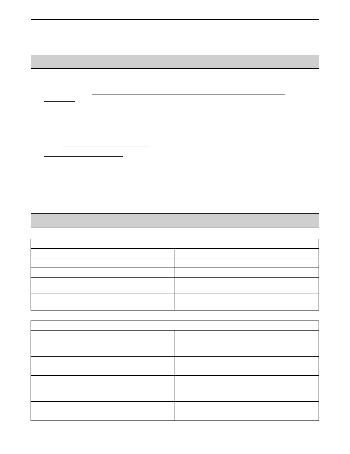
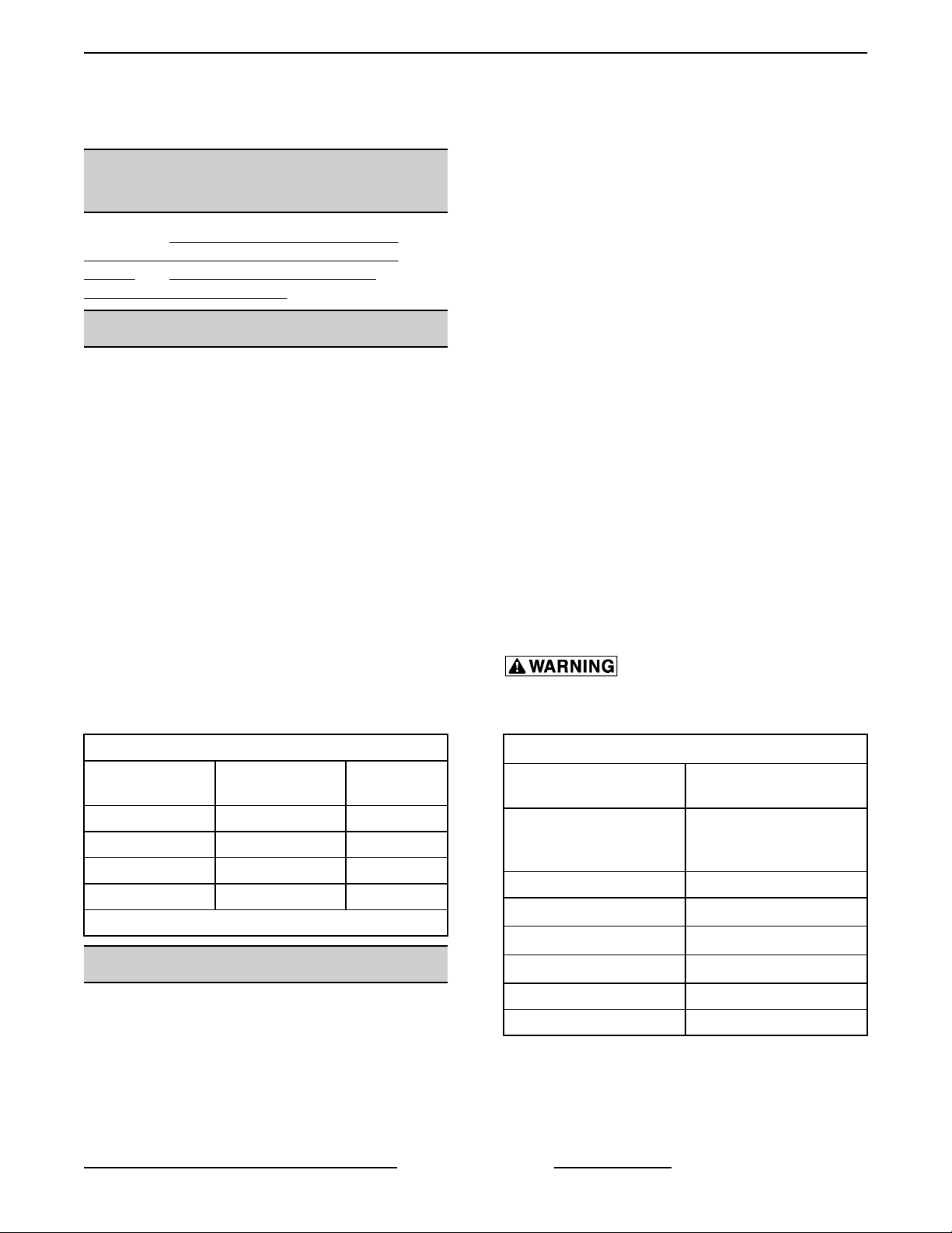
Model Designations
MODEL CONTROLS
C24GA6-BSC Basic 6
C24GA6-DLX Professional 6
C24GA10-BSC Basic 10
C24GA10-DLX Professional 10
* based on 1 inch pan depth
PAN
CAPACITY*
WATER QUALITY STATEMENT
The fact that a water supply is potable is no guarantee
that it is suitable for steam generation. Proper water
quality can improve the taste of the food prepared in
the oven, reduce scale build-up or corrosion, and
extend equipment life. Local water conditions vary
from one location to another and can change
throughout the year. The recommended water
treatment for effective and efficient use of this
Page 7 of 65 F35425 Rev. E (0119)
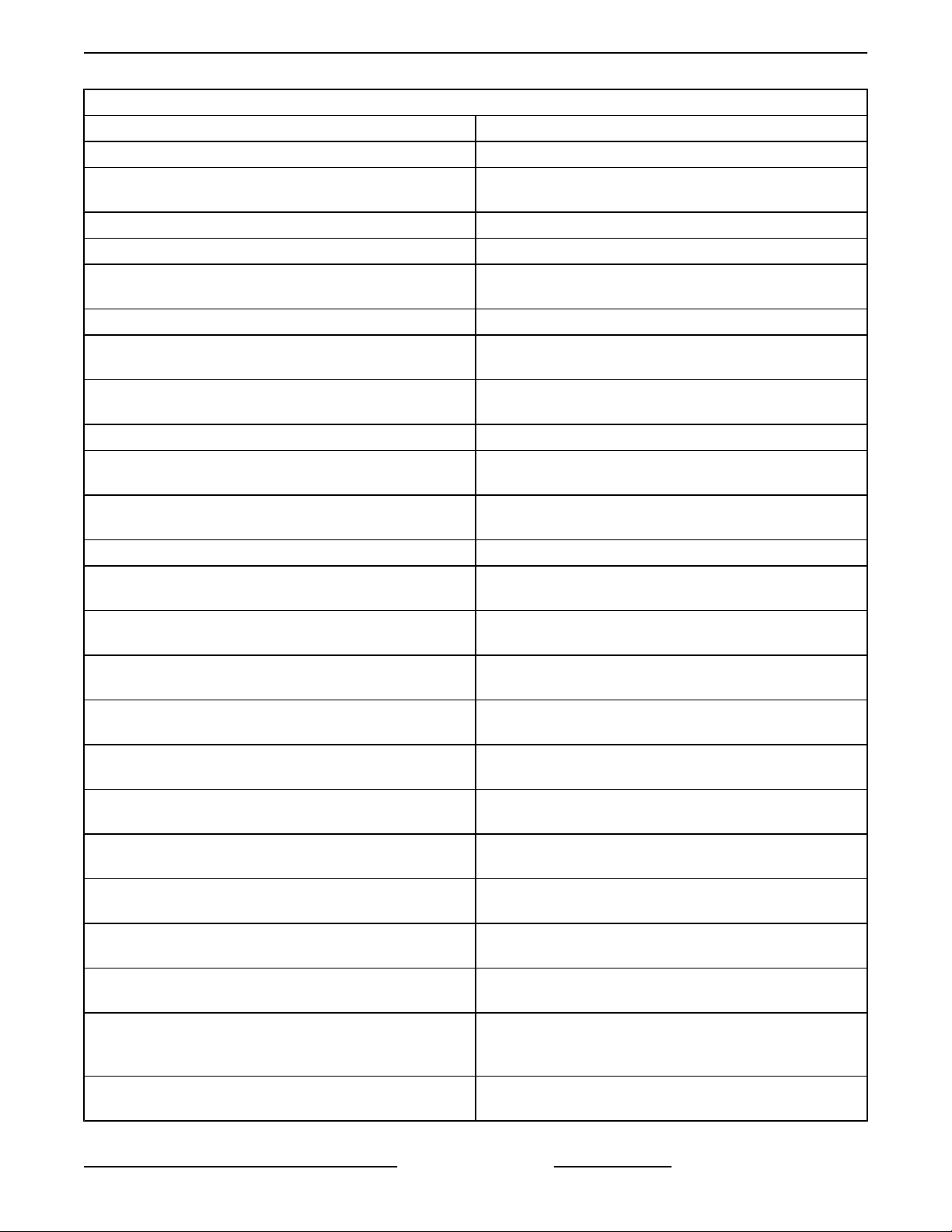
WATER SUPPLY GENERAL GUIDELINES
Supply Pressure
(dynamic flow)
Hardness
Silica less than 13 ppm
Chloramines
Chlorides
Total Chlorine
PH range 7-8
Undissolved Solids less than 5 microns
1
Testing of water is always done AFTER water
filter or water treatment used. Water quality does
change with usage and should be checked after
idle times to see if the condition worsens.
2
2
4
30-60 psig
less than 3 grains (17.1
ppm = 1 grain of
hardness)
zero
less than 30 ppm
zero
1
3
Page 8
C24GA AND C24DA SERIES CONVECTION STEAMER - GENERAL
2
A carbon block filter system should always be
used to remove Chlorine and Chloramine. If a
water softener is used, a carbon block is still
required. Check with your local water treatment
specialist for proper sizing and replacement
intervals for the carbon block cartridge.
3
If the Chlorides exceed 30 ppm and the oven is
used more than 8 hours during the day in steam
or combination mode, the cavity will require
rinsing every 8 hours. Failure to do so will result
in corrosion and rusting of the oven cavity and
interior parts. A Reverse Osmosis water treatment
system can be installed to eliminate chlorides
from the water and reduce the hardness.
Preventative washing and rinsing may be needed
more than once a day to prevent compounding of
contaminants inside cavity.
4
Total Chlorine of 4.0 ppm is the max limit for the
building water supply. A carbon block filter must
still be used to remove all Chlorine and
Chloramines from the water. Failure to do so will
result in corrosion and rust in the cooking cavity,
which is not covered under warranty.
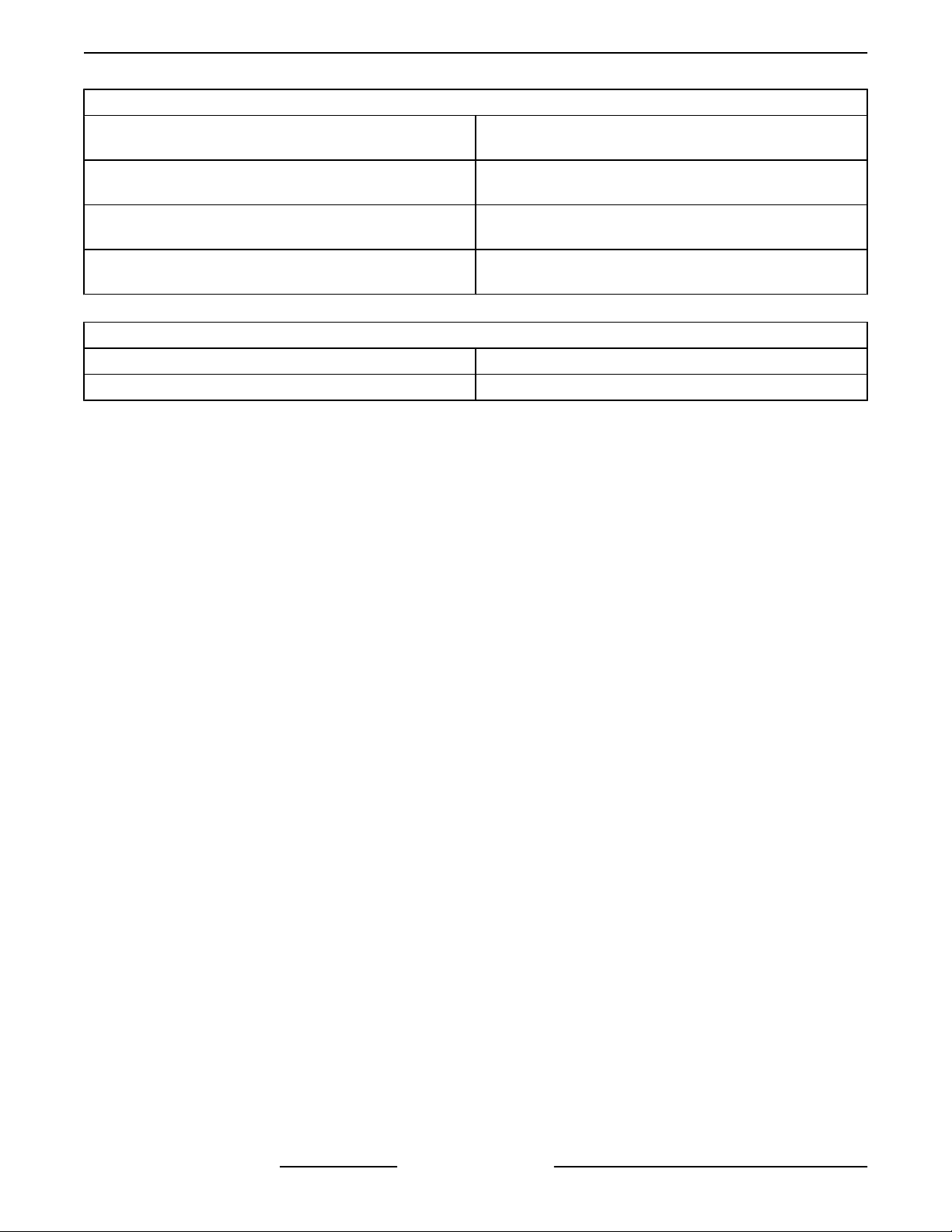
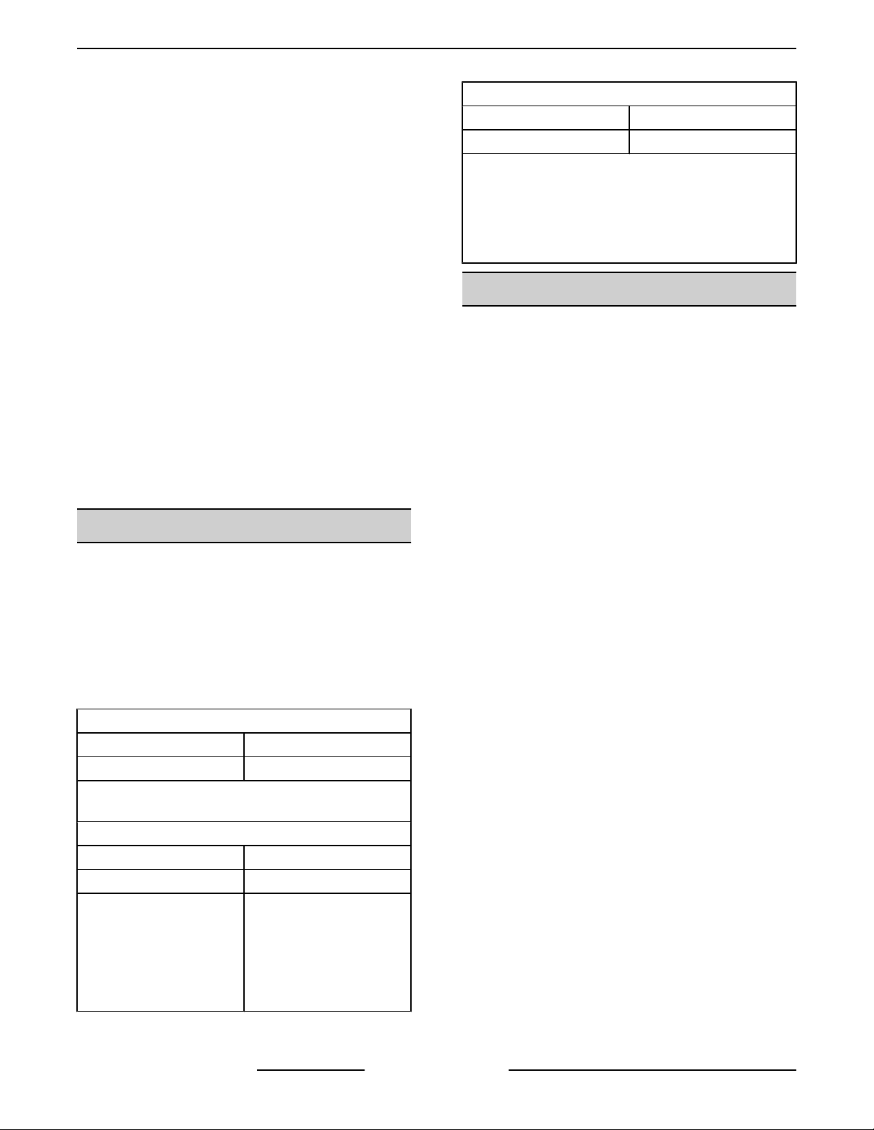
SPECIFICATIONS
Burner Pressure**
Hot .4" to .5" WC.
Cold .33" to .35" WC
** The blower air pressure reading will be higher
when the steam generator is hot vs cold. If the
steam generator has been on for 15 minutes or
more, the operating condition is considered hot.
24 volt transformer needs to be disconnected
when checking blower speed settings.
TOOLS
Standard
• Standard set of hand tools.
• VOM with minimum of NFPA-70E CATIII 600V,
UL/CSA/TUV listed. Sensitivity of at least 20,000
ohms per volt and the ability to measure DC
micro amps. Meter leads must also be rated at
CAT III 600V.
• Temperature tester (thermocouple type).
• Manometer.
• Gas leak detection equipment. (Must be resistant
to reaction of propane gas).
Electric
120VAC/60HZ/1 phase (proper ground required).
NOTE: Do not connect this unit to a ground-fault
circuit-interrupter (GFCI) 125-volt, single-phase, 15and 20-ampere receptacle. Electronic burner ignition
systems are prone to nuisance tripping and possible
ignition failure.
Gas Pressures
Gas Supply Pressure*
Natural 7.0" - 10.5" W.C.
Propane 11.0" - 13" W.C.
* Maximum supply pressure can not exceed 14"
W.C. (1/2 psig).
Gas Manifold Pressure
Natural 2.5" W.C.
Propane 10.0" W.C.
Blower Air Pressure
NOTE: Blower settings
are only made on units up
to serial number
463024849, soloranics
burner is not adjustable.
0.35" W.C. - Cold
.45" W. C. - Hot
• Clear silicone sealant.
Special
• Requires U-inclined (Grainger P/N 3T294) or
digital (Grainger P/N 4JZ78) manometer capable
of reading in 0.01" WC increments. Used for
measuring gas manifold pressures and blower
air pressures.
• RTV 109 for securing gasket to door.
• Loctite® 271.
• Screwdriver, 1/8 X 4 cabinet tip.
• Scale Release PN 854893-13 (14 oz).
• SPS620V Red Filter Head (Kit P/N
854306-00013).
• SMF620 Black Head (Kit P/N 857487-00620).
• Combustion analyzer needed for Soloronics
burner assembly set up procedures.
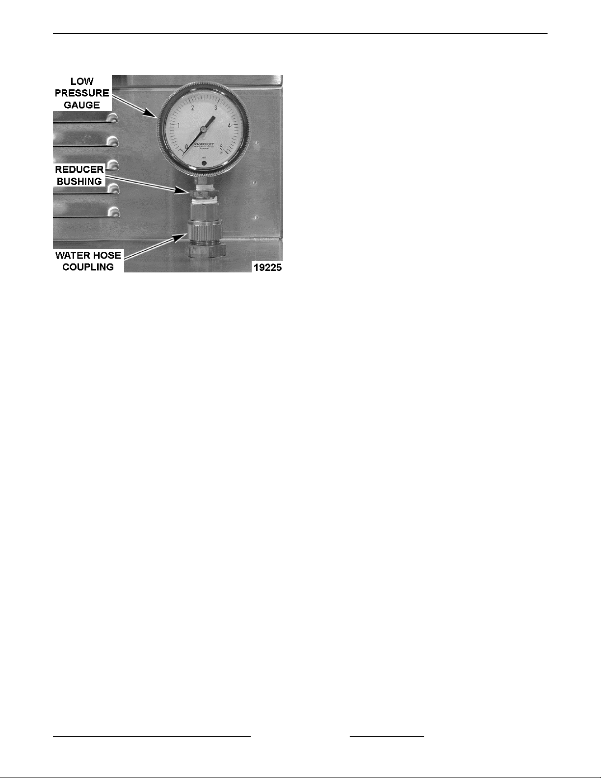
• Pressure Gauge Assembly
• Low Pressure Gauge - 0 to 5 psi.
recommended (Grainger Part No. 2C641).
• Water Hose Coupling - swivel type
(Grainger Part No. 4KG87).
• Reducer Bushing (Grainger Part No.
6MN61).
F35425 Rev. E (0119) Page 8 of 65
Page 9
C24GA AND C24DA SERIES CONVECTION STEAMER - GENERAL
• Pipe thread sealant (as required).
Fig. 1
• Pressure gauge and fittings to check inlet water
pressure for condensate connection.
Page 9 of 65 F35425 Rev. E (0119)
Page 10
C24GA AND C24DA SERIES CONVECTION STEAMER - REMOVAL AND REPLACEMENT OF PARTS
REMOVAL AND REPLACEMENT OF PARTS
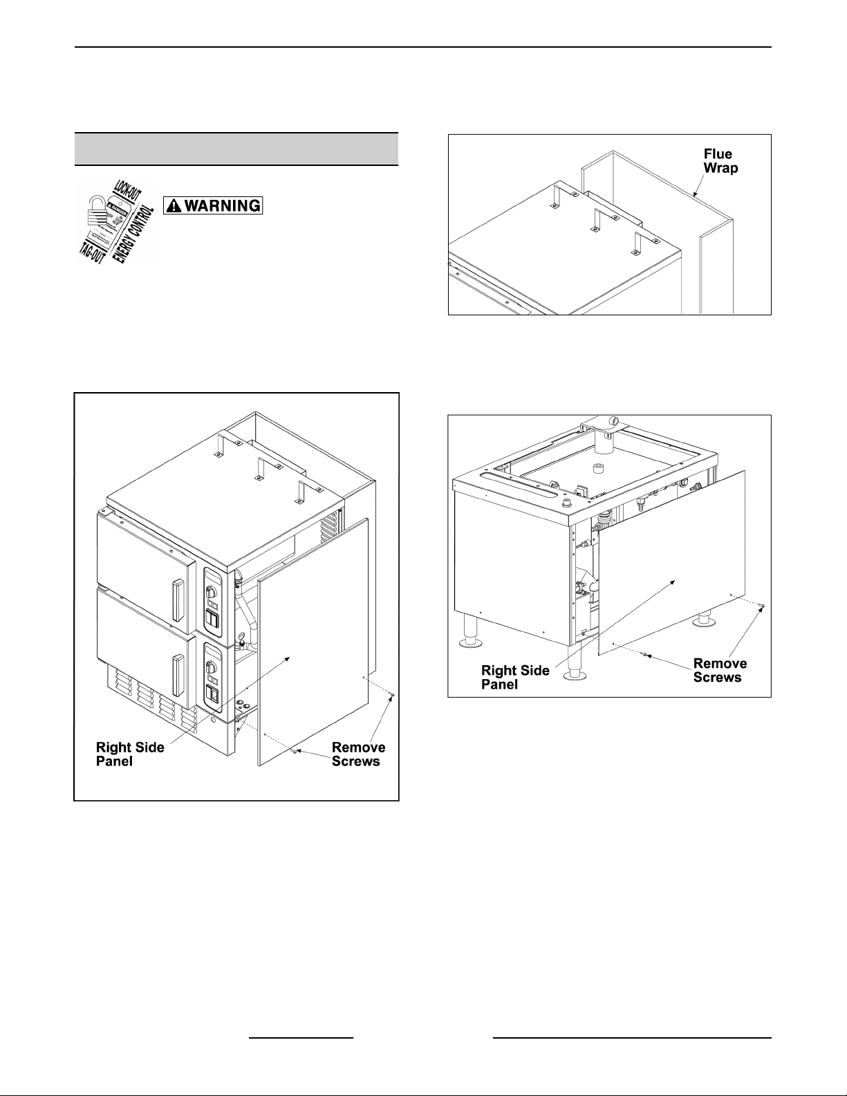
COVERS AND PANELS
Disconnect the electrical power to
the machine and follow lockout /
tagout procedures.
Cooking Compartment Side Panels
NOTE: Removal of left side panel is identical to the
procedure for the right side panel.
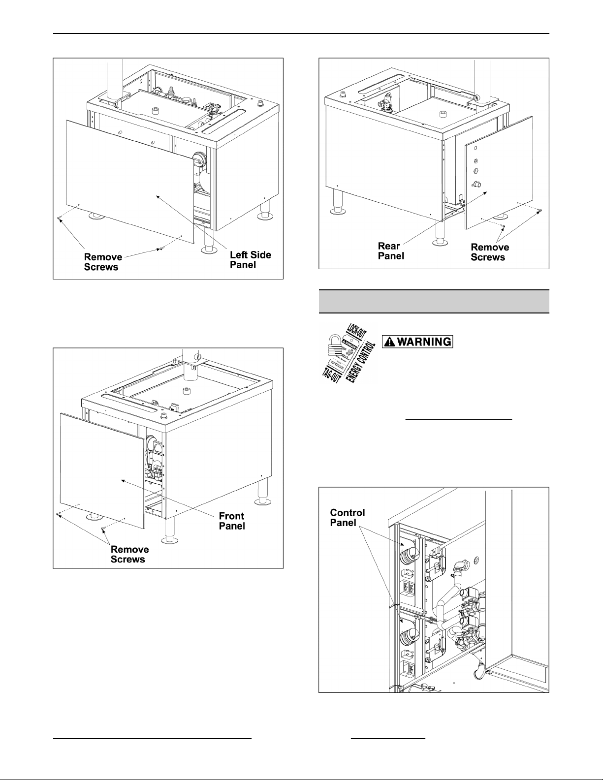
1. Remove the screws then remove the side panel
from the compartment.
Fig. 3
Cabinet Base Right Side Panel
1. Remove the screws then remove the right side
panel from the cabinet base.
Fig. 4
Cabinet Base Left Side Panel
1. Remove the screws then remove the left side
Fig. 2
Cooking Compartment Flue Wrap
1. Remove left and right side panels from
compartment. Remove screws that secure flue
wrap.
F35425 Rev. E (0119) Page 10 of 65
panel from the cabinet base.
Page 11
C24GA AND C24DA SERIES CONVECTION STEAMER - REMOVAL AND REPLACEMENT OF PARTS
Fig. 7
Fig. 5
Cabinet Base Front Panel
COMPARTMENT CONTROLS-OLD
1. Remove the screws then remove the front panel
from the cabinet base.
Fig. 6
Cabinet Base Rear Panel
Disconnect the electrical power to
the machine and follow lockout /
tagout procedures.
1. Remove compartment right side cover as
outlined under COVERS AND PANELS.
2. Remove the component being replaced.
3. Reverse the procedure to install the replacement
component, then check steamer for proper
operation.
NOTE: Electrical components are connected to the
rear panel. Be prepared to note wires and disconnect
when removing rear panel.
1. Remove the screws then remove the rear panel
from the cabinet base.
Page 11 of 65 F35425 Rev. E (0119)
Fig. 8
Page 12
C24GA AND C24DA SERIES CONVECTION STEAMER - REMOVAL AND REPLACEMENT OF PARTS
COOKING COMPARTMENT DOOR
Removal
1. Close Door.
2. Remove compartment left SIDE PANEL.
3. Remove nuts from top door support bracket.
Fig. 9
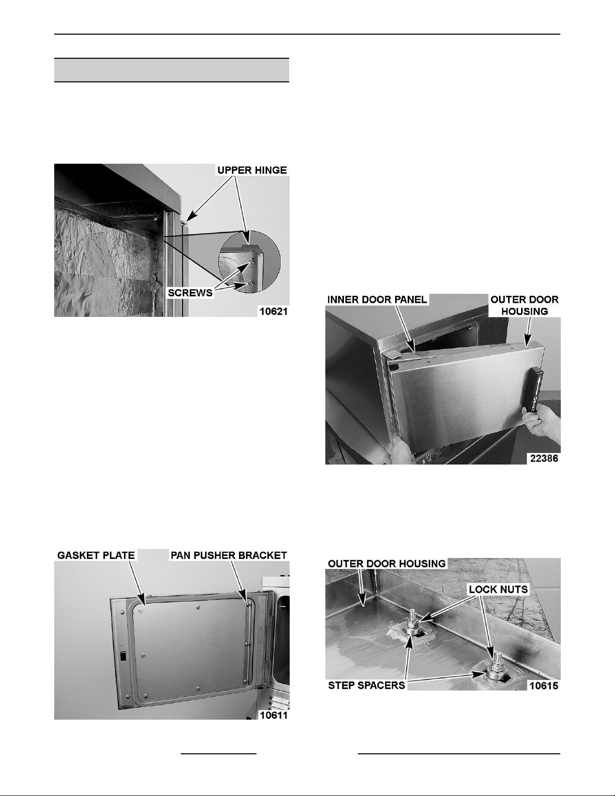
4. Open door slightly, and while holding door, pull
upper hinge away from front panel.
3. Remove the gasket plate.
4. Remove gasket from inner door panel.
5. Remove RTV from bottom part of inner door
panel. Apply new RTV 109 to bottom of door
where shown when assembling gasket to door.
6. Place a small amount of RTV109 into the inner
door panel gasket screw holes before assembly.
7. Position the new gasket on gasket plate and
reverse procedure to install
NOTE: Damage to the gasket sealing surface, such
as nicks or cuts, will cause steam leakage.
Handle Removal
1. Open the door.
2. Remove screws from the top and bottom of the
door.
5. Pull upper hinge out of upper door hinge bushing.
6. Lift door assembly up and off lower door hinge.
7. Reverse the procedure to install and check for
proper operation.
8. Reinstall parts removed in reverse order of
removal.
9. Check door for fit and proper sealing of gasket.
Gasket
1. Open the door.
2. Remove the shoulder screws and pan pusher
bracket from gasket plate.
Fig. 11
3. Pull outer door housing away from inner door
panel starting at the hinge side of door to
separate the door halves.
4. Remove lock nuts and stepped spacers from
threaded studs of door handle.
Fig. 10
F35425 Rev. E (0119) Page 12 of 65
Fig. 12
Page 13
C24GA AND C24DA SERIES CONVECTION STEAMER - REMOVAL AND REPLACEMENT OF PARTS
5. Reverse procedure to install. When installing the
spacers, the smaller diameter fits into the slot in
the door and the latch. Use Loctite 271 to secure
fasteners.
Handle Installation
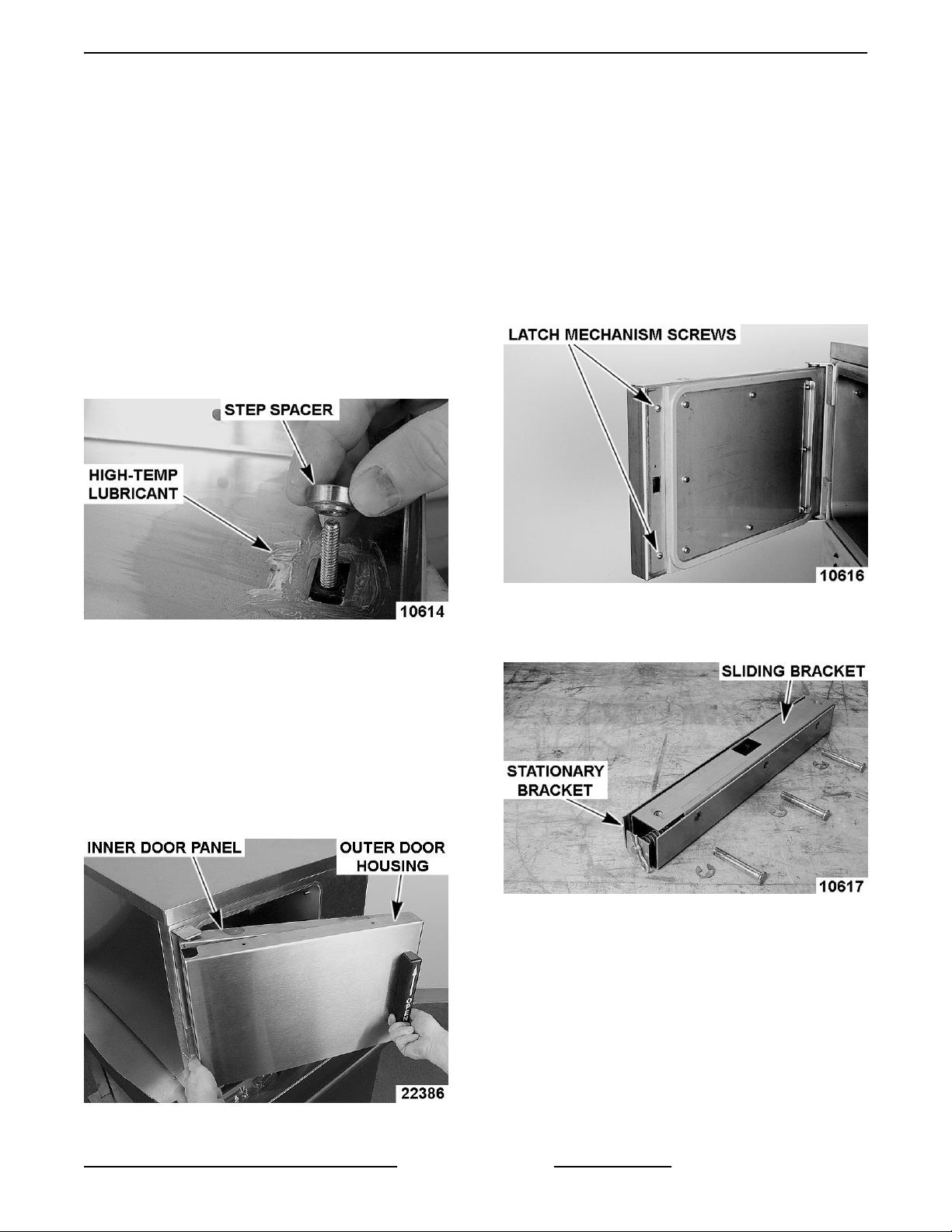
1. Apply Lubriplate 630AA around slots of outer
door housing where step spacers contact
housing.
2. Install door handle into outer door housing such
that hinge side of door housing is to the left and
arrow on handle is pointed upward.
3. Install step spacer with smaller radius toward
handle and door housing. Smaller radius is a slip
fit with outer door housing slot.
8. Apply Loctite 7471 Primer N and Loctite 242 to
threads of screws before assembling.
9. Install screws to secure door halves together.
10. Check opening and closing operation of door.
Latch Assembly and Removal
1. Separate outer door housing assembly from
inner door panel as outlined under DOOR
HANDLE REMOVAL.
2. Remove screws securing latch assembly to inner
door panel and remove latch mechanism.
Fig. 13
4. Install lock nuts and tighten until no gap exists
between handle, step spacer and lock nut. Do not
over-tighten lock nuts.
5. Close inner door panel so that latch mechanism
engages striker on front panel.
6. Install outer door housing onto inner door panel.
7. Align the top and bottom screw holes of outer
door housing with inner door panel.
Fig. 15
3. Remove E-clip from latch assembly pins and pull
pins from latch mechanism.
Fig. 16
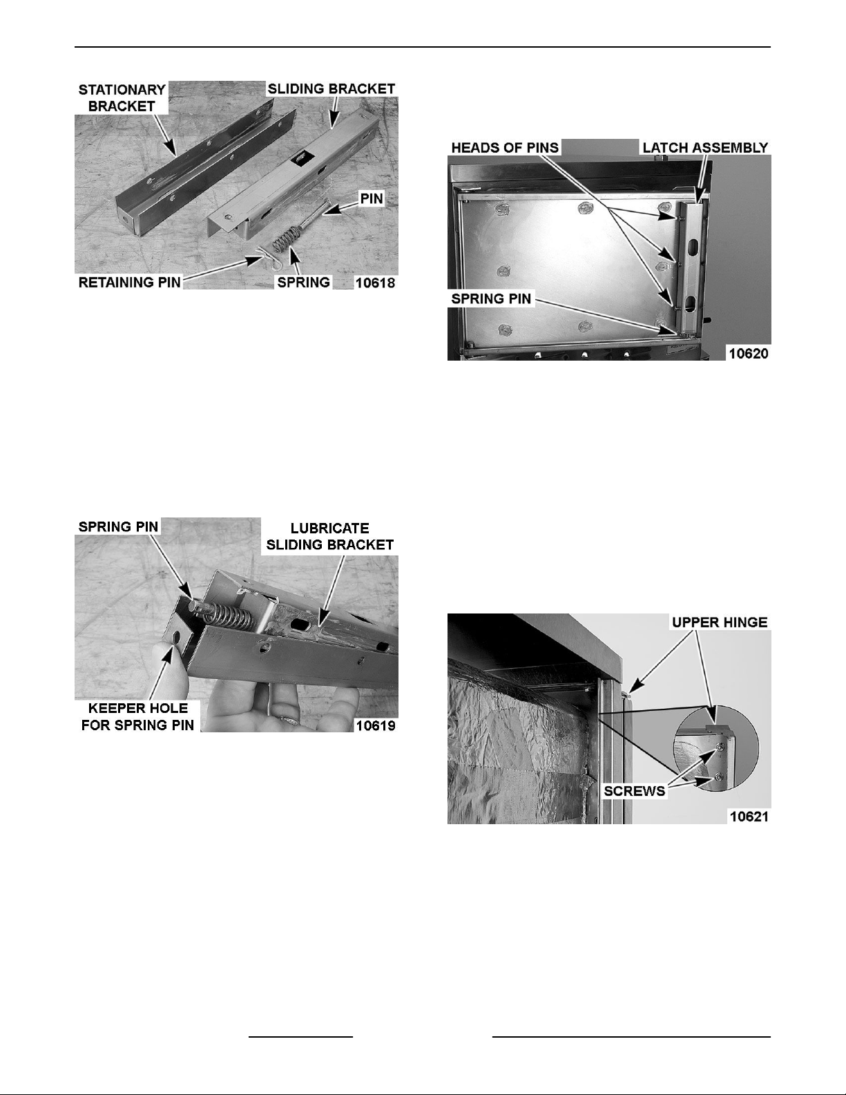
4. Remove retaining pin from spring pin.
5. Separate sliding bracket from stationary bracket.
Fig. 14
Page 13 of 65 F35425 Rev. E (0119)
Page 14
C24GA AND C24DA SERIES CONVECTION STEAMER - REMOVAL AND REPLACEMENT OF PARTS
A. Apply Loctite 271 to threads of screws
before assembly and secure latch assembly
to inner door panel.
Fig. 17
Latch Assembly
1. Apply Lubriplate 630AA to sides of sliding
bracket.
2. Insert spring pin into bottom of sliding bracket.
A. Place spring over spring pin.
3. Assemble sliding bracket into stationary bracket.
4. While holding head of spring pin against bottom
of sliding bracket, insert spring pin into keeper
hole in bottom of stationary bracket.
2. Install outer door housing assembly as outlined
in DOOR HANDLE INSTALLATION.
3. Check opening and closing operation of door.
4. Check steamer for proper operation and leaks
around door seal
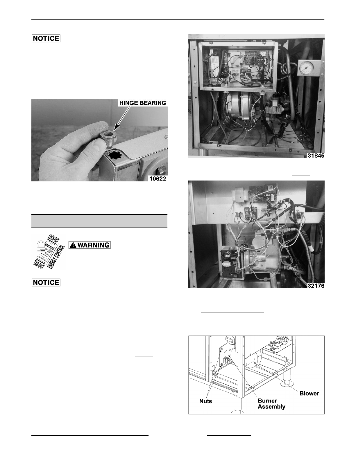
Hinge Bearings
Fig. 19
Fig. 18
A. Secure spring pin in place with retaining pin.
NOTE: Install pins such that heads of pins will be
facing inward toward hinge side of inner door panel
when latch assembly is installed.
5. Install pins to assemble stationary and sliding
brackets together.
A. Secure pins into position with E-clip.
Latch Installation
1. Install latch assembly onto inner door panel with
spring pin toward bottom of door panel.
1. Close door.
2. Remove left SIDE PANEL.
3. Remove nuts from upper hinge located inside
front panel.
Fig. 20
4. Open door slightly, and while holding door, pull
upper hinge away from front panel.
5. Pull upper hinge out of upper door hinge bearing.
6. Lift door assembly up and off lower door hinge.
7. Pry hinge bearing out from door assembly.
8. Remove outer door housing.
F35425 Rev. E (0119) Page 14 of 65
Page 15
C24GA AND C24DA SERIES CONVECTION STEAMER - REMOVAL AND REPLACEMENT OF PARTS
Do not drive bearing into place. The inner door panel
could be damaged. Press bearing into position.
NOTE: When replacing door hinge bearings, replace
both hinge bearings.
9. Position replacement hinge bearing over hinge
opening in door assembly.
Fig. 22
CURRENT PRODUCTION SHOWN IN Fig. 23
Fig. 21
10. Reassemble parts removed in reverse order.
11. Check door for fit and proper door gasket sealing.
MAIN BURNER
Disconnect the electrical power to
the machine and follow lockout /
tagout procedures.
In the previous production (up to serial number
463024849) blower assembly components were
separate (gas valve, air pressure switch, blower, and
ignition module). Current production blower assembly
(starting at serial number 463024850) is one unit and
the air pressure switch is not required. The ignition
module has changed locations and the wire harness
is different. NOTE and VERIFY all wire connections.
PREVIOUS PRODUCTION SHOWN IN Fig. 22
Fig. 23
1. Remove front and side covers as outlined under
COVERS AND PANELS.
2. Disconnect the gas line at gas combination
control valve.
Fig. 24
Page 15 of 65 F35425 Rev. E (0119)
Page 16
C24GA AND C24DA SERIES CONVECTION STEAMER - REMOVAL AND REPLACEMENT OF PARTS
3. Disconnect wires to burner assembly.
4. Remove the nuts securing burner to tank.
5. Drop blower end of burner assembly slightly
down to clear control box and push all interfering
wires out of the way so that burner can be pulled
out of tank.
6. Reverse procedure to install burner assembly.
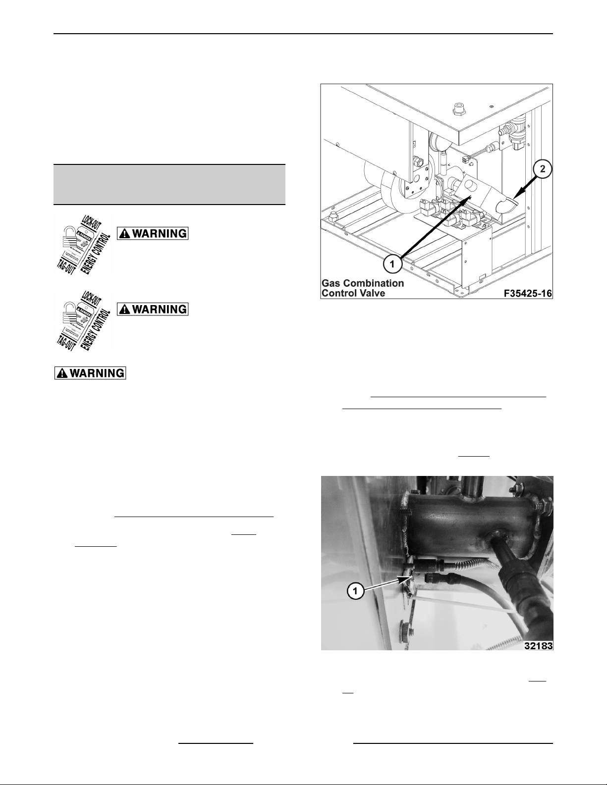
GAS COMBINATION CONTROL
VALVE
Disconnect the electrical power to
the machine and follow lockout /
tagout procedures.
Fig. 25
Shut off the gas before servicing the
unit and follow lockout / tagout
procedures.
All gas joints disturbed during servicing must be
checked for leaks. Check with a soap and water
solution (bubbles). Do not use an open flame.
A. CHECK ALL JOINTS PRIOR TO THE GAS
VALVE (SOLENOID) BEFORE LIGHTING THE
UNIT.
B. CHECK ALL JOINTS BEYOND GAS VALVE
(SOLENOID) AFTER UNIT IS LIT.
1. Remove FRONT AND RIGHT SIDE PANELS.
2. Remove main burner as outlined in MAIN
BURNER.
3. Disconnect electrical supply wires running to gas
combination control valve.
4. Disconnect pilot gas supply tube from control.
5. Disconnect pipe connections on each side of gas
combination control valve.
6. Reverse procedure to install.
7. Verify PILOT BURNER ADJUSTMENT (ONLY
UNITS WITH ADJUSTABLE PILOT).
NOTE: No pilot burner adjustment needed if unit has
Solaronics burner assembly.
ADJUSTABLE PILOT (1, Fig. 26) BURNER
SHOWN
F35425 Rev. E (0119) Page 16 of 65
Fig. 26
SOLARONICS BURNER ASSEMBLY (1, Fig.
27) NON-ADJUSTABLE PILOT
Page 17
C24GA AND C24DA SERIES CONVECTION STEAMER - REMOVAL AND REPLACEMENT OF PARTS
Fig. 27
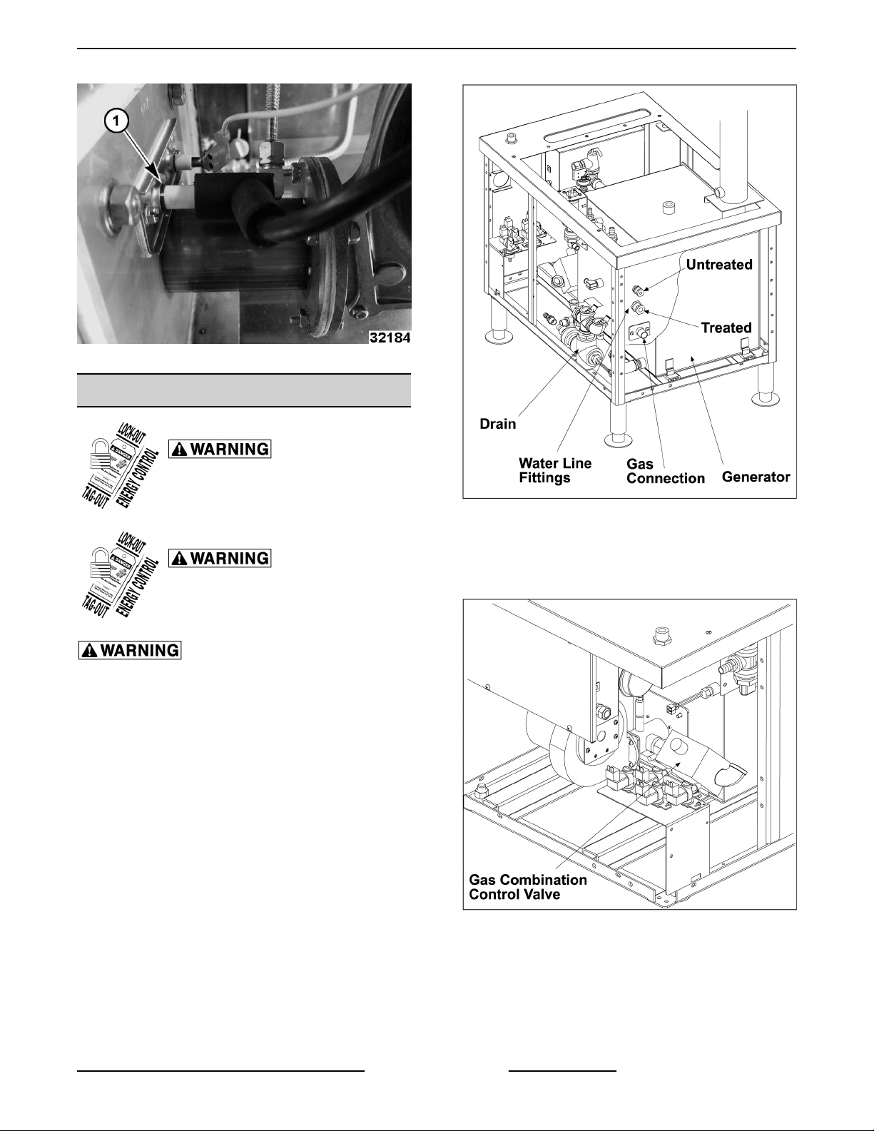
GENERATOR ASSEMBLY
Disconnect the electrical power to
the machine and follow lockout /
tagout procedures.
Shut off the gas before servicing the
unit and follow lockout / tagout
procedures.
All gas joints disturbed during servicing must be
checked for leaks. Check with a soap and water
solution (bubbles). Do not use an open flame.
A. CHECK ALL JOINTS PRIOR TO THE GAS
VALVE (SOLENOID) BEFORE LIGHTING THE
UNIT.
B. CHECK ALL JOINTS BEYOND GAS VALVE
(SOLENOID) AFTER UNIT IS LIT.
1. Drain the generator and allow steamer to cool, if
necessary.
Fig. 28
2. Remove rear and side panels.
3. Disconnect gas line at gas combination control
valve.
Fig. 29
NOTE: Earlier production units show in graphics.
Page 17 of 65 F35425 Rev. E (0119)
Page 18
C24GA AND C24DA SERIES CONVECTION STEAMER - REMOVAL AND REPLACEMENT OF PARTS
Fig. 30
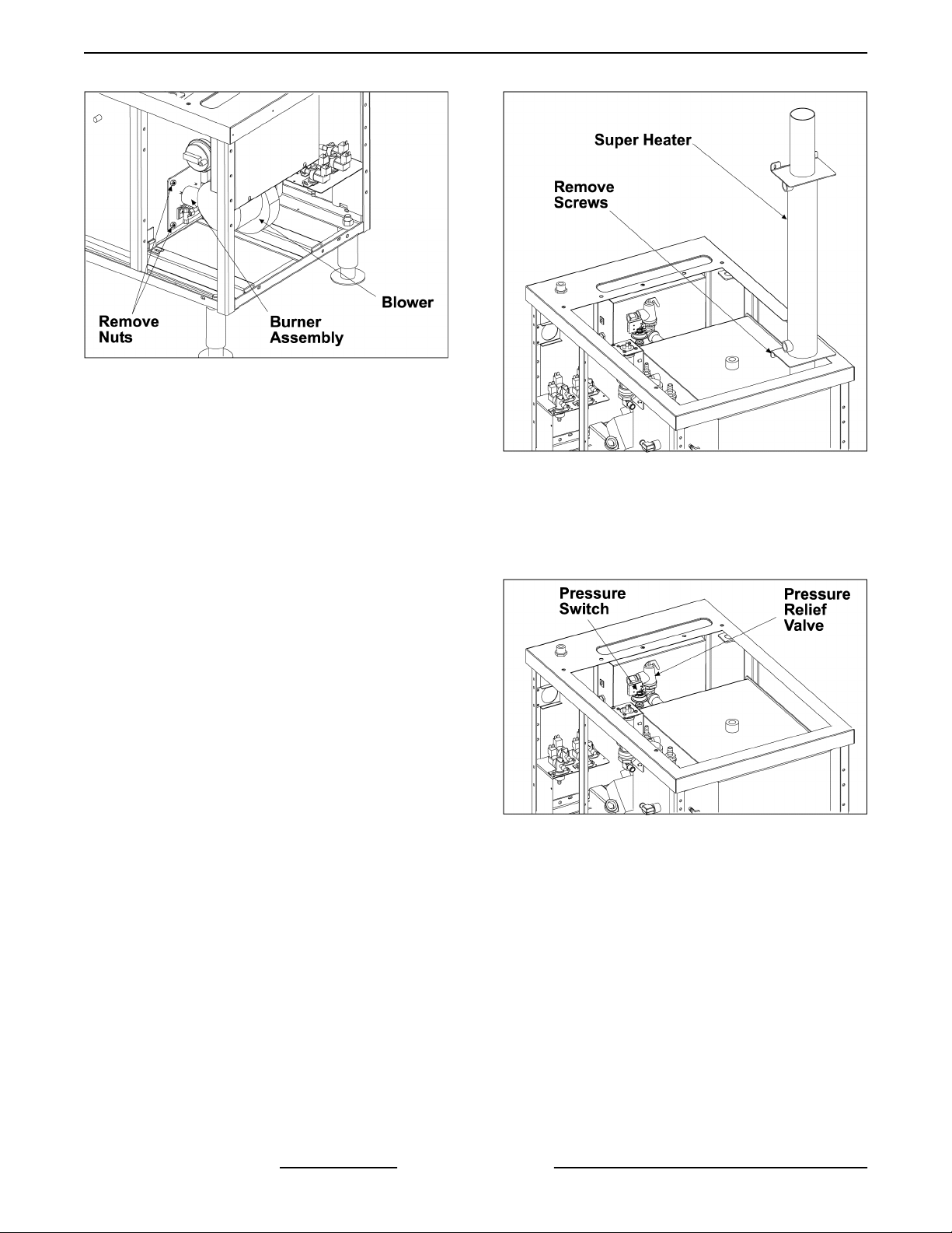
4. Disconnect wires to burner assembly.
5. Disconnect wires from gas combination control
valve.
6. Remove the nuts securing the burner to
generator.
7. Drop blower end of burner assembly slightly
down to clear control box and push all wires out
of the way so that burner can be pulled out of
tank.
17. Rotate pressure relief valve coupling to allow
pressure relief valve to be rotated about 90° so
that valve is below generator top level.
18. Remove pressure switch from generator.
Fig. 31
8. Disconnect wires from the operating pressure
switch.
9. Loosen hose clamp attaching lower flexible water
line at back panel and use a wrench to disconnect
barb fitting from main inlet water connection.
10. Loosen hose clamp attaching upper flexible
water line at back panel and use a wrench to
disconnect barb fitting from main inlet water
connection.
11. Remove water line from generator. Remove
steam hoses from steam trap and supply to super
heater.
12. Disconnect gas tubing from rear panel.
13. Remove steel drain tube at tank.
14. Disconnect union between tank and drain.
15. Loosen cable clamp screws securing electrical
cable at rear panel so that cable is free to move.
16. Remove screws to free super heater and lift
super heater off flue pipe, if applicable.
Fig. 32
19. Remove bolts attaching front of generator to
frame.
F35425 Rev. E (0119) Page 18 of 65
Page 19
C24GA AND C24DA SERIES CONVECTION STEAMER - REMOVAL AND REPLACEMENT OF PARTS
Fig. 33
20. Move any interfering components out of the way,
then push generator slightly forward to
disengage feet and remove generator from rear
of cabinet.
21. Reverse procedure to install generator.
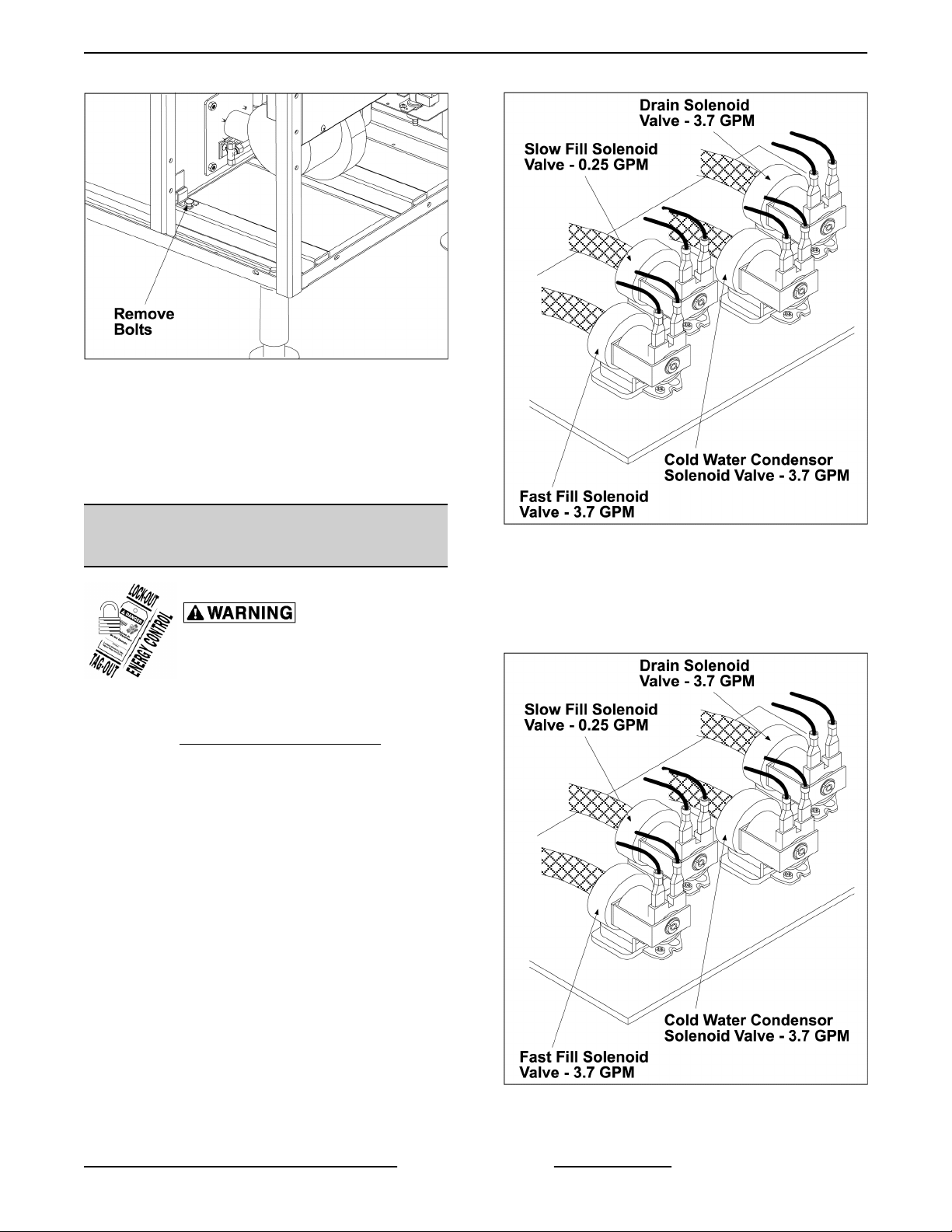
FILL AND COLD WATER SOLENOID
VALVES
Disconnect the electrical power to
the machine and follow lockout /
tagout procedures.
1. Turn off water supply to steamer.
2. Remove FRONT AND SIDE COVERS.
PREVIOUS PRODUCT SHOWN
Fig. 34
3. Pull quick connect power leads off solenoid valve
being serviced.
4. Disconnect water lines to solenoid valve being
serviced and remove solenoid valve from unit.
Fig. 35
CURRENT PRODUCTION SHOWN
Page 19 of 65 F35425 Rev. E (0119)
Page 20

C24GA AND C24DA SERIES CONVECTION STEAMER - REMOVAL AND REPLACEMENT OF PARTS
Fig. 37
SOLARONICS BURNER ASSEMBLY (1) NONADJUSTABLE PILOT
Fig. 36
5. . Reverse procedure to install solenoid valve.
PILOT/SPARK PROBE FLAME
SENSOR (ONLY UNITS WITH
ADJUSTABLE PILOT)
Shut off the gas before servicing the
unit and follow lockout / tagout
procedures.
NOTE: Only for units with adjustable pilot burner.
ADJUSTABLE PILOT BURNER (1)
Fig. 38
1. Remove MAIN BURNER ASSEMBLY.
2. Disconnect gas tube from pilot burner and
remove pilot assembly screws.
F35425 Rev. E (0119) Page 20 of 65
Fig. 39
Page 21

C24GA AND C24DA SERIES CONVECTION STEAMER - REMOVAL AND REPLACEMENT OF PARTS
3. Replace malfunctioning flame sensor or pilot
assembly.
4. Reverse procedure to install a new flame sensor
or pilot assembly.
5. Check for proper operation.
BLOWER CONTROL RELAY (K3)
Shut off the gas before servicing the
unit and follow lockout / tagout
procedures.
Fig. 41
1. Remove CABINET BASE FRONT PANEL.
Disconnect the electrical power to
the machine and follow lockout /
tagout procedures.
NOTE: Starting with production Serial No. 463008610
and higher will have blower control relay (K3) installed.
C24GA 6&10 production gas steamers will begin
using a blower control relay (K3) to carry blower motor
current instead of the operating pressure switch
contacts.
K3 relay must be installed into earlier production units
that are having a Solaronics burner assembly
installed.
NOTE: K3 relay has been used since April 2013 on
units with serial number 463008610 and higher.
ADJUSTABLE PILOT BURNER (1)
2. Locate blower control relay (K3) in front of
steamer base.
3. Note and disconnect lead wires from relay
terminals.
4. Remove (2) mounting screws.
Fig. 40
SOLARONICS BURNER ASSEMBLY (1) NONADJUSTABLE PILOT
Fig. 42
5. Reverse procedure to install and check for proper
operation.
Page 21 of 65 F35425 Rev. E (0119)
Page 22

C24GA AND C24DA SERIES CONVECTION STEAMER - SERVICE PROCEDURES AND ADJUSTMENTS
SERVICE PROCEDURES AND ADJUSTMENTS
Certain procedures in this section require electrical test or measurements while power is
applied to the machine. Exercise extreme caution at all times and follow Arc Flash procedures.
If test points are not easily accessible, disconnect power and follow Lockout/Tagout
procedures, attach test equipment and reapply power to test.
BLOWER AIR PRESSURE ADJUSTMENT (ONLY UNITS WITH ADJUSTABLE
PILOT)
NOTE: This adjustment requires a U-inclined or digital manometer capable of reading in 0.01" WC increments to
make the proper blower air pressure adjustments. If the required manometer is not available, do not proceed with
the adjustments.
Shut off the gas before servicing the unit and follow lockout / tagout procedures.
NOTE: Only for units with adjustable pilot burner.
ADJUSTABLE PILOT BURNER (1)
SOLAROINICS BURNER ASSEMBLY (1) NON-
ADJUSTABLE PILOT
F35425 Rev. E (0119) Page 22 of 65
Page 23

C24GA AND C24DA SERIES CONVECTION STEAMER - SERVICE PROCEDURES AND ADJUSTMENTS
Blower Air Pressure (COLD)
NOTE: Initial adjustment of blower air pressure should only be made from a cold starting condition.
1. Turn gas supply off.
2. Remove Cabinet Base Front Panel.
3. Remove plug on the outlet side of gas valve and install manometer. Refer to Fig. 45.
Fig. 45
4. Disconnect 24VAC transformer lead wire.
Disconnecting 24 VAC transformer lead wire will prevent ignition sequence from starting when power switch
is on.
5. Verify manometer reading is zero.
NOTE: If ignition module is powered up when checking blower settings it will also affect the blower speed.
6. On Older Machines Only, to access blower speed adjustment screw:
A. Remove 4 screws securing blower shroud to blower.
B. Re-install screws only and continue with next step.
7. Connect power to machine and turn main power switch on.
8. Allow steam generator to fill (approximately 3 to 5 minutes).
NOTE: When water level reaches the low level cut off probe (LLCO) the blower will turn on but ignition module
will not begin sparking to light main burner.
9. Check blower air pressure.
• Reading should be 0.33" to 0.35" WC (cold). If pressure is not correct, adjust blower speed potentiometer
as necessary to achieve correct pressure (clockwise to increase, counterclockwise to decrease).
10. Disconnect power from machine. Leave power switch on to prevent steam generator from draining.
A. Connect 24 VAC transformer lead.
B. Turn gas supply on and connect power to machine (ignition sequence will immediately start). If ignition
module has status LED(s), the ignition sequence can be monitored via LED flash codes.
Page 23 of 65 F35425 Rev. E (0119)
Page 24

C24GA AND C24DA SERIES CONVECTION STEAMER - SERVICE PROCEDURES AND ADJUSTMENTS
C. Allow main burner to light. If main burner does not light within 90 seconds, turn power switch off. Wait 5
minutes before re-lighting.
D. Repeat until main burner lights.
If main burner continues not to light, check AIR PRESSURE SWITCH ADJUSTMENT (ONLY UNITS
WITH ADJUSTABLE PILOT). Adjustment of air pressure switch should only be made when machine cold.
11. Verify manifold gas pressure is 2.5" WC (nat) or 10.0" WC (propane). Adjust pressure setting as necessary
(clockwise to increase, counterclockwise to decrease).
If manifold pressure cannot be set correctly, verify gas supply pressure to machine. If machine has pressure
regulator installed in the supply line to gas valve, perform pressure adjustments.
Blower Air Pressure (HOT)
1. Allow steam generator to operate for at least 15 min. (to verify settings when hot & fine tune if necessary).
2. Disconnect power from machine.
3. Leave power switch on to prevent steam generator from draining.
4. Disconnect 24VAC lead wire from ignition module.
5. Verify manometer reading is zero.
6. Connect power to machine. The blower will turn on but ignition module will not begin sparking to light main
burner.
7. Check blower air pressure .
• Reading should be 0.40" to 0.50" WC (hot). If pressure is not correct, adjust the blower speed
potentiometer to achieve 0.45" WC (clockwise to increase, counterclockwise to decrease).
8. Disconnect power from machine. Leave power switch on to prevent steam generator from draining.
9. Connect 24 VAC lead wire to ignition module.
10. Connect power to machine. Ignition sequence will immediately start and main burner will light. If ignition module
has status LED(s), the ignition sequence can be monitored via LED flash codes.
11. Verify manifold gas pressure did not change.
12. Disconnect power and turn gas supply off. Remove manometer and install pipe plug on gas valve manifold
pressure port.
13. Install blower shroud.
14. Reconnect power and turn gas supply on.
15. Steamer is ready for use.
SOLARONICS BURNER
ADJUSTMENT (STARTING AT
SERIAL NUMBER 463024850)
1. Remove RIGHT SIDE PANEL.
2. Check incoming gas pressure to solenoid valve.
A. Loosen screw with flat head screwdriver (1,
Fig. 46) to open pressure tap.
F35425 Rev. E (0119) Page 24 of 65
Page 25

C24GA AND C24DA SERIES CONVECTION STEAMER - SERVICE PROCEDURES AND ADJUSTMENTS
Fig. 46
B. Use manometer to measure incoming gas.
• Natural Units- 5" W.C.
• Propane Units - 10" W.C.
C. Turn adjustment screw (1, Fig. 47) all the
way in until it bottoms out.
Fig. 47
D. Back adjustment screw out.
• Natural Units - 6 to 6 ½ Turns.
Fig. 48
4. Analyze combustion.
A. Insert analyzer (1, Fig. 49) into exhaust flue
(2, Fig. 49) as shown.
• Propane Units - 5 to 5 ½ Turns.
3. Check solenoid on/off switch to verify it is in the
ON (Fig. 48) position.
Page 25 of 65 F35425 Rev. E (0119)
Page 26

C24GA AND C24DA SERIES CONVECTION STEAMER - SERVICE PROCEDURES AND ADJUSTMENTS
AIR PRESSURE SWITCH
Analyzer wand must be in center of exhaust flue and
at least 2" down into flue.
ADJUSTMENT (ONLY UNITS WITH
ADJUSTABLE PILOT)
Blower air pressure adjustment must be performed
before proceeding with this procedure.
The air pressure switch senses the pressure level
produced by the blower for combustion. When the
pressure is sufficient, the switch closes and supplies
power to the ignition control module. The gas ignition
sequence starts to light the gas pilot and then main
burner. If gas pilot is not lighting (valve not energized),
the ignition control module may not be receiving
power, assuming the minimum water level is satisfied.
Check the air pressure switch operation then adjust if
necessary as outlined in the procedure below.
Fig. 49
B. Verify requirements.
Burner Combustion Requirements
Measure Natural Gas Propane Gas
Supply Pressure
CO2
Percentage
CO (ppm, Air
Free)
C. Turn gas valve adjustment screw clockwise
or counterclockwise to achieve burner
combustion requirements.
D. Install side panel.
E. Verify operation.
7.0" to 10.5"
W.C.
7.0% (+/- 0.5%) 8.0% (+/-0.5%)
Less than 100
ppm
11.0" to 13.0"
W.C.
Less than 100
ppm
Fig. 50
1. Turn the power switch off.
2. Remove the front panel from the cabinet base.
A. Inspect the air intake to the blower for debris
build up and clogging.
1) If debris is found, clean it away from the
air intake.
B. Turn the power switch on and verify main
burner ignition.
1) If burner ignites no adjustment to the
pressure switch setting is necessary.
2) If burner does not ignite, proceed to
step 3.
3. Turn the main gas valve to off.
4. Adjust the air pressure switch setting as follows:
A. Turn the adjustment screw fully clockwise to
the highest setting.
F35425 Rev. E (0119) Page 26 of 65
Page 27

C24GA AND C24DA SERIES CONVECTION STEAMER - SERVICE PROCEDURES AND ADJUSTMENTS
B. Slowly turn the adjustment screw
counterclockwise until main gas valve
energizes then add 1/2 turn to the
adjustment. The screw head should not
extend out past the screw housing.
1) If gas valve energizes, proceed to step
5.
2) If gas valve does not energize, check
the following:
a. Remove the lead wires from the
switch and verify with a meter that
the switch contacts are closing
with the blower on. If necessary,
continue to turn the adjustment
screw several turns
counterclockwise to close the
switch contacts.
b. If the switch contacts are not
closing, turn the power switch off,
remove the pressure switch from
the manifold and check the air
orifice for debris build up and
clogging. If debris is found, clean
it away from the orifice.
5. Restart the ignition sequence by turning the
power switch off, waiting 3 seconds, then back
on. .
A. Listen or use a meter for gas pilot ignition to
verify operation.
1) If gas pilot ignition is successful, listen
for main gas burner ignition to verify
operation.
B. Verify the pilot and main burner both ignite
in succession.
1) Restart the ignition sequence by
rapidly turning the power switch off
then back on. A rapid switching is
needed to keep the generator from
starting automatic blowdown.
C. Listen for main gas burner ignition to verify
operation
PILOT BURNER ADJUSTMENT
(ONLY UNITS WITH ADJUSTABLE
PILOT)
c. Replace the orifice, pressure
switch and connect the lead wires
to the switch. Turn the power
switch on and adjust the pressure
switch again as outlined in steps
4A and 4B. Verify the pilot gas
valve is energizing. d. If the pilot
gas valve is not energizing and
power is available to the pressure
switch, turn the power switch off.
Replace with a new air pressure
switch and adjust the switch as
outlined from step 3 thru the end
of this procedure.
NOTE: Only for units with adjustable pilot burner.
Shut off the gas before servicing the
unit and follow lockout / tagout
procedures.
Page 27 of 65 F35425 Rev. E (0119)
Page 28

C24GA AND C24DA SERIES CONVECTION STEAMER - SERVICE PROCEDURES AND ADJUSTMENTS
ADJUSTABLE PILOT BURNER (1)
SOLARONICS BURNER ASSEMBLY (1) NON-
ADJUSTABLE PILOT
F35425 Rev. E (0119) Page 28 of 65
Page 29

C24GA AND C24DA SERIES CONVECTION STEAMER - SERVICE PROCEDURES AND ADJUSTMENTS
1. Shut the gas off at combination gas valve.
2. Remove cover from manifold pressure tap.
3. Install a barb fitting and connect manometer.
4. Turn on the steamer, let generator fill.
5. Verify air pressure setting is between 0.35" and 0.4" W.C.
6. Verify air pressure switch adjustment.
Fig. 53
7. Turn off the steamer.
8. Remove pilot assembly from burner.
9. Remove cap from pilot adjustment screw.
10. Using cabinet tip screwdriver turn pilot adjustment screw all the way in.
11. Back out pilot adjustment screw five (5) turns counter clockwise. This will get it close, may need tweaked.
12. Remove the wire from main valve (wire # 35).
13. Turn on the steamer, let generator fill.
14. Turn on combination gas valve.
15. Observe pilot flame; adjust pilot flame length using pilot adjustment screw. Set flame to approx. 2" long (Pilot
flame should be a nice blue flame; with slight touch of yellow permissible at tip.)
Page 29 of 65 F35425 Rev. E (0119)
Page 30

C24GA AND C24DA SERIES CONVECTION STEAMER - SERVICE PROCEDURES AND ADJUSTMENTS
Fig. 54
16. Turn off the machine.
17. Re-install pilot, reconnect wire # 35.
18. Turn on the machine, let generator fill
19. Observe proper functioning of gas burner.
Operating Pressure Switch
1. Remove CABINET BASE FRONT PANEL. Pressure switch is located behind control box.
Fig. 55
2. Turn power on and let generator come up to pressure.
3. After ready light comes on, turn one of the cooking compartment timers to exhaust steam from the generator.
F35425 Rev. E (0119) Page 30 of 65
Page 31

C24GA AND C24DA SERIES CONVECTION STEAMER - SERVICE PROCEDURES AND ADJUSTMENTS
Fig. 56
4. Observe generator pressure gauge reading for several cycles and verify that the burner is cycling off at 3 psi.
CURRENT PRODUCTION SHOWN (1, Fig. 57)
PREVIOUS PRODUCTION SHOWN (Fig. 58)
Fig. 57
Page 31 of 65 F35425 Rev. E (0119)
Page 32

C24GA AND C24DA SERIES CONVECTION STEAMER - SERVICE PROCEDURES AND ADJUSTMENTS
Fig. 58
Thumb Wheel Adjustment
The thumb wheel directly below the microswitch changes both the cut-out (off) and the cut-in (on) points of the
operating Pressure Switch.
Turn the thumb wheel to obtain the proper cut-out (off) setting. Turning thumb wheel clockwise increases the
pressure. The cut-out (off) off setting should be 3 psi.
Fig. 59
F35425 Rev. E (0119) Page 32 of 65
Page 33

C24GA AND C24DA SERIES CONVECTION STEAMER - SERVICE PROCEDURES AND ADJUSTMENTS
Fig. 60
Inlet Water/Steam Strainer
1. Unscrew the cap from the body.
Fig. 61
2. Remove the screen and any foreign particles trapped in the opening.
3. Rinse the screen thoroughly to remove accumulated debris and replace the screen in the valve body. If the
screen cannot be thoroughly cleaned, replace it with a new one.
4. Reinstall the cap.
Page 33 of 65 F35425 Rev. E (0119)
Page 34

C24GA AND C24DA SERIES CONVECTION STEAMER - SERVICE PROCEDURES AND ADJUSTMENTS
AUTOMATIC IGNITION SYSTEMS
NOTE: Only for units with adjustable pilot burner.
ADJUSTABLE PILOT BURNER (1)
When the main power switch is turned on and the water level is above LLCO, the ignition control module is energized
with 24 volts between terminals five and six. High voltage is sent from terminal nine to the spark electrode and an
output of 24 volts is sent from terminals two and three to the pilot coil in the combination valve, allowing gas to flow
to the pilot. The sparking will continue for 90 seconds or until the flame sensor has confirmed that an adequate pilot
flame is present.
Once the pilot flame is confirmed, a 24 volt output from terminal one will be sent to the gas combination control
valve.
TERMINAL NO. DESCRIPTION
Voltage (24 VAC) will be present on MV terminal #1 with the pilot sensing electrode
1
2 Common MV/PV.
3
4 Ground (burner).
5 Ground (24 VAC Neutral).
6 24 VAC Input.
8 Flame Sensor.
9 Flame Sensor.
PREVIOUS PRODUCTION SHOWN
sensing an adequate pilot flame. This output will remain present as long as the pilot
flame remains adequate.
The Pilot Voltage (24 VAC) will be present on terminal #3 at the instant an input voltage
is supplied to the module. This voltage will remain present on terminal #3 providing an
adequate pilot flame is established within 90 seconds. In the event that an adequate
pilot flame is not established within 90 seconds this output voltage will drop out.
SOLARONICS BURNER ASSEMBLY (1) NON-
ADJUSTABLE PILOT
F35425 Rev. E (0119) Page 34 of 65
Page 35

C24GA AND C24DA SERIES CONVECTION STEAMER - SERVICE PROCEDURES AND ADJUSTMENTS
Fig. 64
CURRENT PRODUCTION SHOWN SOLARONICS
Fig. 65
Page 35 of 65 F35425 Rev. E (0119)
Page 36

C24GA AND C24DA SERIES CONVECTION STEAMER - SERVICE PROCEDURES AND ADJUSTMENTS
Spark Ignition Control Test
The ignition control module and ignition control module transformer are located in the electronics enclosure behind
the generator base front cover.
PREVIOUS PRODUCTION SHOWN IN Fig. 66
1. Check for earth ground.
PREVIOUS PRODUCTION SHOWN IN Fig. 67
Fig. 66
Fig. 67
2. Check to ensure that all electrical terminal connections on the ignition control module and the igniter are clean
and tight.
3. Verify that the ignition control module and the igniter have good ground wire connections. The igniter mounting
bracket should have good metal to metal contact to its mounting surface.
4. Turn the main power switch on. Make sure LLCO light is on.
5. Check for 24VAC output on the ignition control module transformer.
F35425 Rev. E (0119) Page 36 of 65
Page 37

C24GA AND C24DA SERIES CONVECTION STEAMER - SERVICE PROCEDURES AND ADJUSTMENTS
A. If 24VAC is present, then replace ignition control module and retest. It may take up to 3 seconds for the
module to reset if main power is turned off then back on.
B. If 24VAC is not present, then ensure that transformer is receiving 120VAC input. If ignition control module
transformer is receiving proper voltage, then replace ignition control module transformer and retest.
IGNITION TEST
1. The gap between the spark probe and the pilot
burner should be approximately 1/8". If the gap
appears to be excessive or poor sparking is
occurring, remove the electronic ignition pilot and
adjust gap.
PREVIOUS PRODUCTION SHOWN
PREVIOUS PRODUCTION SHOWN
2. Inspect the ceramic flame rod insulator for cracks
or evidence of exposure to extreme heat, which
can permit leakage to ground. If either of these
conditions exist, then replace the pilot igniter
assembly.
3. Check the ignition cable for tightness or
damaged insulation.
4. 4. Check unit for proper operation.
Inspect the pilot burner orifice. This should be
approximately 1/8" in diameter and free of debris.
Fig. 68
MANIFOLD PRESSURE ADJUSTMENT (ONLY UNITS WITH ADJUSTABLE
PILOT)
Page 37 of 65 F35425 Rev. E (0119)
Page 38

C24GA AND C24DA SERIES CONVECTION STEAMER - SERVICE PROCEDURES AND ADJUSTMENTS
Disconnect the electrical power to the machine and follow lockout / tagout procedures.
Shut off the steam before servicing the unit and follow lockout / tagout procedures.
All gas joints disturbed during servicing must be checked for leaks. Check with a soap and water solution
(bubbles). Do not use an open flame.
ADJUSTABLE PILOT BURNER (1)
A. CHECK ALL JOINTS PRIOR TO THE GAS VALVE (SOLENOID) BEFORE LIGHTING THE UNIT.
B. CHECK ALL JOINTS BEYOND GAS VALVE (SOLENOID) AFTER UNIT IS LIT.
1. Remove FRONT, RIGHT AND LEFT SIDE
PANELS
2. Turn the gas combination control valve off.
SOLARONICS BURNER ASSEMBLY (1) NON-
ADJUSTABLE PILOT
F35425 Rev. E (0119) Page 38 of 65
Page 39

C24GA AND C24DA SERIES CONVECTION STEAMER - SERVICE PROCEDURES AND ADJUSTMENTS
1. For access to compartment controls, remove the
right side panel from the cooking compartment as
outlined under COVERS AND PANELS.
2. Check door switch for proper operation.
Fig. 71
3. To measure the manifold pressure, remove the
1/8" NPT plug (pressure tap) on the outlet side of
the gas combination control valve and attach a
manometer.
4. Turn the gas supply valve and the main power
switch on. Allow generator to fill.
5. Verify burner air pressure is 0.35" to 0.4" W.C.
6. Turn the gas combination control valve on and
wait until main burner lights.
7. Observe the manometer pressure reading and
compare to the pressure chart below.
GAS PRESSURE READINGS (INCHES W.C.)
MANIFOL
D
GAS
TYPE
Natrual 2.5 7.0 5.0 14
Propan
e
* If the incoming line pressure is less than the
minimum stated, then the manifold pressure
cannot be set correctly.
8. Once the correct pressure has been set, turn the
power switch and gas supply off, replace the
adjustment screw cap and 1/8" NPT plug
(pressure tap) on the outlet side of the valve.
10.0 11.0 11.0 14
RECOMMENDED MIN
LINE*
MA
X
3. Check cooking timer function and contact
position. See SCHEMATICS under
ELECTRICAL OPERATION.
4. Check that timer motor operates when
connected to power. If a problem is found in
timer, replace it, do not take timer apart.
5. Check wiring for damaged insulation (no short
circuit).
6. Check that all connections and terminals are
securely fastened (no open circuits).
7. Check that all connections are made according
to compartment control wiring diagram.
Latch Adjustment
If the cabinet door jams and cannot be opened, do not
force or pry the door, as damage will occur.
First, try lifting up on the bottom of the door at the
handle end to disengage the latch. If that does not
work, remove the right side panel from the cooking
compartment as outlined under COVERS AND
PANELS.
The striker that catches on the door latch is located
behind the front face of the cooking cavity. Remove
the nut from the striker to release it from the panel.
Fig. 72
DOOR
COOKING COMPARTMENT
Controls
Page 39 of 65 F35425 Rev. E (0119)
Page 40

C24GA AND C24DA SERIES CONVECTION STEAMER - SERVICE PROCEDURES AND ADJUSTMENTS
4. Once the proper slot alignment has been set,
hold the striker close to its base using an open
end wrench, add Loctite to the threads, then
tighten the striker nut. Be careful not to damage
the striker slot when tightening or door may not
latch properly. Do not over tighten as the striker
will begin to turn and change alignment.
5. If door does not open easily, add shims as
necessary between striker and cabinet front.
6. Repeat steps 2 thru 4.
DELIME GENERATOR
READ AND FOLLOW THE INSTRUCTIONS ON THE
DELIMING MATERIAL PACKAGE. AVOID
CONTACT WITH SKIN AND EYES. WEAR PLASTIC
OR RUBBER GLOVES AND SAFETY GOGGLES
Fig. 73
Once the nut and washer have been removed, door
will open freely.
Remove any burrs on the striker that may cause the
latch to stick. Reinstall the striker and adjust so door
will not jam.
Striker Adjustment
1. Reinstall the striker with the slot pointing upwards
and hand tighten nut only.
WHEN HANDLING. WASH THOROUGHLY AFTER
HANDLING. IF DELIMING SOLUTION COMES IN
CONTACT WITH THE SKIN OR EYES, RINSE
THOROUGHLY WITH CLEAN WATER.
THE STEAMER AND ITS PARTS ARE HOT. USE
CARE WHEN OPERATING, CLEANING OR
SERVICING THE STEAMER. THE COOKING
COMPARTMENT CONTAINS LIVE STEAM. STAY
CLEAR WHEN OPENING DOOR.
2. Close the door to center the striker in the oval
mounting hole.
3. Open the door and check the striker’s slot for
horizontal alignment. The slot on the striker must
be kept horizontal in order for the door latch to
catch it properly and latch.
Fig. 74
□ Delime generator weekly. Refer to TOOLS for
Scale Release information.
This procedure is not intended to take the place of a
water treatment program. Use instructions supplied
with Scale blocker PM kit when filter is being replaced.
NOTE: Scale blocker® water treatment system is
used for preventative maintenance and must be
performed according to water hardness. Refer to
schedule chart below. 84 oz of Scale Release is
required to delime generator when no water treatment
is used other than carbon block. 28 oz (2 bags) is
required for C24GA6 & 10.
Hardness (Grains) Deliming Schedule
0 to 5 6 Months
5 to 10 3 Months
10 to 15 Monthly
15 to 20 2 Weeks
20+
Other Water Treatment Is
Required
F35425 Rev. E (0119) Page 40 of 65
Page 41

C24GA AND C24DA SERIES CONVECTION STEAMER - SERVICE PROCEDURES AND ADJUSTMENTS
Delime Generator Procedure
Items Required (not provided)
• Deliming material. Refer to TOOLS for scale
release information.
• Funnel.
• Plastic or rubber gloves.
• Safety goggles or face shield.
• Measuring cup.
• 1 gallon container for mixing deliming solution.
• Petrol-Gel Lubricant or equivalent food grade
grease for coating deliming port threads.
NOTE: Deliming solution may cause the surface of
aluminum measuring tools to tarnish or etch.
C24GA (Automatic Drain) 11 US GAL Capacity
Steam Generator.
1. Turn power switch off. Wait 15 minutes for steam
generator to completely drain and the drain valve
to close.
2. Turn cooking timers to off.
8. Turn power switch on. When ready light comes
on, allow steamer to remain on for 45 minutes.
9. After 45 minutes, turn cooking timers on for 5
minutes to delime the steam tubes and nozzles.
10. After 5 minutes, turn power switch off and allow
steam generator to completely drain, 5 minutes.
11. Turn power switch on. When ready light comes
on, turn cooking timers on for 30 seconds to rinse
steam tubes and nozzles.
12. Turn power switch off and allow steam generator
to completely drain.
13. Turn cooking timers to off.
14. Repeat steam generator rinse one time.
15. Clean exterior and interior using a mild solution
of soap and water.
Do not use cleaners containing chlorides or chlorine.
16. Rinse with clean water then dry with a soft cloth.
3. Prepare deliming solution according to the
instructions on deliming material package.
Follow all manufacturers’ instructions.
4. Remove delime port cap on top of unit and insert
funnel into delime port.
Fig. 75
5. Pour deliming solution into steam generator
slowly to avoid spillage.
6. Remove funnel from delime port then rinse port
with clean water.
7. Lightly coat delime port threads with Petrol-Gel
then install delime port cap. Cap must be
installed and tightened securely at all times.
Leave compartment doors open when not in use.
17. The steamer is ready for operation or shutdown.
COOKING CYCLE TEST
General
During a cooking cycle, the gas heating system will
cycle on and off as necessary to maintain steam
pressure in the generator. When the steam pressure
in the steam generator reaches 4 psi for the first time
after machine is switched on, the steam header
pressure relay latches on and supplies power to
compartment controls. Ready light will illuminate
(header pressure relay remains latched until the
machine is switched off).
Test operation of the cooking compartment controls.
1. With both timer knobs at the off position, open the
compartment doors.
2. Observe that no steam has entered the cooking
compartments.
3. Close the doors.
4. Set both timer knobs at 2 minutes.
5. Confirm that the ready lights go off, the cooking
lights come on, and steam begins to enter the
compartments.
6. After one minute, open both doors.
Page 41 of 65 F35425 Rev. E (0119)
Page 42

C24GA AND C24DA SERIES CONVECTION STEAMER - SERVICE PROCEDURES AND ADJUSTMENTS
7. Observe that steam has ceased to enter each
compartment, cooking lights go back to ready,
and one minute is remaining on each cook timer.
8. Close the doors.
9. Confirm that steam delivery and cook timing
resume.
10. Observe the floor drain to ensure that live steam
from the compartments is being cooled by cold
water from the cold water condenser solenoid
valve.
11. When the timer knobs reach 0, confirm that the
buzzers sound, steam delivery ceases, cooking
lights go off, and ready lights come on.
12. To silence the buzzers, turn the timer knobs to off
position.
13. Turn the main power switch off to remove power
from the steamer, and confirm that the red light
goes out and generator drains.
PROBE INSPECTION
It is recommended that the generator be thoroughly
inspected for excessive scale and lime build-up on a
quarterly basis. In hard water areas or for units heavily
used, a shorter interval should be used. This
inspection consists of the following:
Drain Plug -
Probe -
Controls -
PREVIOUS PRODUCTION MODELS
Remove clean-out port plug to
check for scale.
A check of lime build-up on the
water level probe assembly.
check of all generator controls,
including the pressure switches.
Fig. 76
CURRENT PRODUCTION MODELS
Periodic Maintanence
F35425 Rev. E (0119) Page 42 of 65
Fig. 77
MAINTANENCE CHECKS
Page 43

C24GA AND C24DA SERIES CONVECTION STEAMER - SERVICE PROCEDURES AND ADJUSTMENTS
□ DELIME GENERATOR
□ Change carbon block filter every 6 months or per
filter manufacture’s recommendation.
□ Weekly inspect door seals for cuts, tears, or
leaks. Replace as needed.
□ Weekly check filter system pressure, 20 PSI
minimum while filling, and change cartridge(s) if
less or if they are due for replacement.
Yearly Maintanence
Disconnect the electrical power to
the machine and follow lockout /
tagout procedures.
1. Verify power is removed and locked.
2. Turn off water supply to steamer.
3. Verify hoods system is operating per
manufactures specification and is clean and free
of obstructions and grease build up.
Current Production Models
A. Remove FLUE WRAP.
B. remove the “Y” strainer screen with a
5/8“socket or wrench.
C. Clean the screen.
D. Install screen and flue wrap.
6. Inspect screens.
A. Remove the two water supply hoses and
inspect screens in the valve openings. If
dirty remove the screen by prying it out with
a small screw driver. Clean the screen and
reinsert into the valve opening. Reinstall the
water supply hoses making sure the filtered/
treated water hose is connected to the valve
marked treated or filtered water. Improperly
reconnecting the hoses will result in
excessive scale build up and corrosion.
4. Inspect water level probes.
NOTE: Current production probe housing is welded
to generator tank.
A. Remove
B. Remove and inspect water level probes.
C. Clean water level probes if lime scale is
present.
If probes show signs of corrosion or excessive lime
scale build up, replace probes and have water tested.
D. Apply pipe sealant or teflon tape to threads
on probe.
E. Install water level probes.
5. Inspect steam and drain strainers.
NOTE: Current production generatorsonly have "Y"
type strainers located in middle of steam manifold.
Earlier Production Models
A. Remove pipe plugs located on right side of
steam generator.
RIGHT SIDE COVER .
B. Remove steam and drain strainers.
C. Clean strainers.
D. Install strainers.
E. Apply pipe sealant or teflon tape on plug
threads.
Page 43 of 65 F35425 Rev. E (0119)
Page 44

C24GA AND C24DA SERIES CONVECTION STEAMER - ELECTRICAL OPERATION
ELECTRICAL OPERATION
WATER LEVEL CONTROLS
Low Level Cut-Off and Differential Control
The steamer is equipped with three water level
sensing probes (high, low and low level cut-off) and a
single water level control board. The water level
control board performs two functions:
• Provide low level cut-off protection to shut off the
heat source in case the water level drops below
the low level cut-off (LLCO) probe.
• Perform as a differential level control to maintain
the water level between the low and high water
level probes.
The water level control (WLC) has 120VAC across
terminals L1 and L2 which powers the primary side of
the transformer. On one side of the transformer
secondary, power is provided to the control by a series
path through chassis ground (GND). The other side of
the transformer secondary, 12VAC is attached to the
probe that directs power to the other side of WLC relay
coils (LLCO and HL) and to the inverse latching relay
(ILR) electronic circuit of WLC. As water enters the
steam generator, it becomes part of the WLC circuit.
When the water level in steam generator reaches a
probe, that circuit is completed. The inverse latching
relay contacts of WLC are in their shelf state (ILR-1
NO and ILR-2 NC) until WLC is powered.
through the low level probe (LL) and ILR-1 contacts.
With ILR-2 contacts open, HL relay is de-energized
and HL LED turns off. With HL-1 contacts open, the
slow fill solenoid is de-energized, stopping the flow of
water to the steam generator.
As steam is produced during a cooking cycle, the
water level in the generator recedes. When the water
level drops below the low level (LL) probe, power is
removed from the inverse latching relay, HL relay
energizes through ILR-2 and HL contacts change
state. The slow fill solenoid is energized again through
HL-1 to refill the steam generator and HL LED is lit.
The HL relay and LED will toggle on and off during a
cooking cycle as needed.
Fig. 78
When the main power switch is turned on, power is
supplied to the WLC. The high level (HL) relay is
energized, HL LED illuminates and HL-1 normally
open contacts close. The fast fill solenoid is energized
through LLCO-2 normally closed contacts and steam
generator begins fast fill. Power is not transferred to
the slow fill solenoid until the water level reaches the
LLCO probe and the LLCO relay is energized.
When the water level reaches the low level cut-off
(LLCO) probe, LLCO relay is energized and LLCO
LED is lit. The LLCO-2 contacts open, de-energizing
the fast fill solenoid, and the LLCO-1 normally open
contacts close. With LLCO-1 contacts closed, power
is provided to the heating steamer control circuit to
begin steam generation. With HL-1 contacts closed,
the slow fill solenoid is energized and steam generator
continues to fill at a slower rate.
LLCO relay will remain energized and its LED will stay
lit until the water level in steam generator drops below
LLCO probe or main power switch is turned off.
Water level reaches high level (HL) probe, the inverse
latching relay on WLC is energized and locked
SEQUENCE OF OPERATION
Refer to schematic diagrams AI2947 and 22851 to
explain the steamer electrical sequence of operation.
Initial Fill and Preheat
1. Conditions:
A. Steamer connected to:
1) 120VAC and is properly grounded.
2) Cold water supply with correct water
requirements and valve is on.
3) Steamer Connected to proper gas
supply with correct supply pressures
and valve is on.
B. Power switch off.
C. Cold water thermostat open (drain water
temperature below 140°F for drain cooling).
1) Drain cold water condenser (CWC)
solenoid N.C. is de-energized.
F35425 Rev. E (0119) Page 44 of 65
Page 45

C24GA AND C24DA SERIES CONVECTION STEAMER - ELECTRICAL OPERATION
D. Timer delay output off.
1) Drain solenoid valve N.C. is deenergized.
E. Main gas valve knob in on position.
F. Operating pressure switch (N.C.) is closed.
G. Air pressure switch (N.O.) is open.
H. Steam generator empty.
I. Compartment times off and doors are open.
2. Turn power switch on.
A. Time delay relay de-energized.
B. Power light (amber) on control panel is on.
C. 120VAC to - Terminal 5 on cavity relay K2
(N.O. contacts 5/3 provide power to
compartment controls) and water level
control (WLC) terminal L1.
D. 120VAC applied to compartment controls
after cavity relay K1 is energized (generator
at operating pressure).
3. With water level control (WLC) energized. Refer
to WATER LEVEL CONTROL for complete
operation details.
6. Trial for ignition starts.
A. Ignition module generates spark at ignitor/
direct spark.
1) Sparking will continue until an
adequate pilot flame is sensed
maximum 10 seconds. If pilot flame is
not established within the 10 second
ignition trial time, the output to spark
electrode is shut off (sparking stops)
and the output to enrichment and main
valves is locked out.
B. Sparking stops the main burner lights and
flame sense has been proven.
1) Steam generator begins heating.
7. Water level reaches Low Level (L) probe.
A. Power to terminal L on WLC (no switching
action) (input to board level control circuit
present). WLC internal latching relay ILR-1
contacts are open.
8. Water level reaches High Level (HL) probe
(board level control circuit energized and locked).
A. HL led off. WLC HL (high level) relay de-
energized.
A. HL led lit. WLC HL (high level) relay
energized.
1) WLC HL N.O. contacts close.
B. Fast fill solenoid energized through WLC
LLCO relay N.C. contacts. Steam generator
begins fast fill.
4. Water level reaches Low Level Cut-Off (LLCO)
probe.
A. LLCO LED lit. WLC LLCO relay energized.
1) LLCO N.C. contacts open. Fast fill
solenoid de-energized.
2) WLC LLCO N.O. contacts close. Slow
fill solenoid energized through WLC HL
closed contacts. Steam generator
changes to slow fill.
a. Operating pressure switch N.C
contacts engerizes K3 relay for
blower.
b. K3 relay N.O. contact closes and
blower is powered.
c. Air pressure switch N.O. contacts
close providing 120 volts to
transformer.
5. 24VAC out from transformer secondary.
1) HL N.O. contacts open. Slow fill
solenoid de-energized (generator
filling stops).
9. Steam generator pressure reaches 3 psi.
A. Ready light on (green) (compartment
controls).
1) N.C. contacts open. Power removed
from:
a. Burner system.
b. Burner system de-energized
(heating stops).
2) N.O. contacts close. Cavity relay K2
energized.
a. Relay N.O. contacts 5/3 close and
latch - 120VAC to compartment
controls. Relay remains
energized until power switch is
turned off.
b. Ready light (green) is on.
B. Operating pressure switch contacts change
state.
10. Steamer is ready for operation. Refer to
COMPARTMENT CONTROLS.
Water Re-fill (After Initial Fill)
Page 45 of 65 F35425 Rev. E (0119)
Page 46

C24GA AND C24DA SERIES CONVECTION STEAMER - ELECTRICAL OPERATION
1. The water refill cycle will occur whenever the
water level is below the low level probe and will
not affect the operation of either the preheat or
cook cycle.
2. Water level drops below low level (L) probe.
A. HL LED lit. High level coil (HL) energized by
ILR-2 contacts returning to N.C. condition.
1) Internal latching relay coil (ILR) on
WLC de-energized. ILR-1 contacts
return to N.O. condition.
2) WLC (HL) contacts close. Slow fill
solenoid energized.
B. Water level reaches Low Level (L) probe
(input to board level control circuit present).
1) Power to terminal L on WLC (no
switching action).
C. Water level reaches high level (H) probe
(board level control circuit energized and
locked).
1) Internal latching relay coil (ILR) on
WLC energized and locked thru the low
level probe (L) and ILR-1 closed
contacts. HL LED off. WLC HL coil deenergized by ILR-2 contacts opening.
a. WLC (HL) contacts open. Slow fill
solenoid (4SOL) de-energized
(generator filling stops.
3. Steam generator pressure drops below 3 PSI
and operating pressure switch contacts return to
closed position.
4. Time expires on time delay relay. Drain solenoid
valve de-energized (generator empty).
5. Drain water temperature below 120°F. Cold
water thermostat contacts return to open
condition.
Compartment Controls
NOTE: Refer to schematic diagrams AI2947 and
22851 cooking compartment operation. The diagram
shows the upper and lower compartment controls.The
Controls are identical, but function independently
when cooking timers are set during a cook cycle.
1. Power switch is on and steam generator
pressurized.
A. Operating pressure switch closed.
1) Cavity relay K2 energized and N.O.
relay contacts 5/3 close. 120VAC
provided to cooking compartment
control circuit.
2. 2. Door switch contacts closed (compartment
door closed).
A. Ready light (green) is on.
B. Power to terminals 11 and 21 on timer
3. 3. Timer set for timed cooking.
3. Refill cycle repeats until: Timer turned OFF
(generator idle); Or power switch turned off.
A. if power switch is turned off
1) power is removed from generator
control circuit and compartment
controls.
Turning Steamer Off
1. Power switch turned off (power removed from
generator control circuit and compartment
controls).
A. Time delay relay energized and output
activated for 1000 seconds / 16.7 minutes.
1) Drain solenoid valve energized. Valve
opens and steam generator begins
draining.
2. Drain water temperature above 130°F. Cold
water thermostat contacts close (N.O. contacts close on temperature rise).
A. Drain CWC solenoid energized. Drain water
cooled.
F35425 Rev. E (0119) Page 46 of 65
4. A. Timer contacts 11/13 and 21/23 open.
A. A. Timer contacts 11/13 and 21/23 close.
1) Timer motor energized through
contacts 11/13.
2) Steam solenoid and cavity relay K1
energized through contacts 21/23.
a. Cook light (red) is on.
3) Cavity relay K1 N.O. contacts 3/5
close. Cavity cold water condenser
(CWC) solenoid is energized to cool
cavity drain condensate.
a. If the upper and lower
compartment timers are both set,
cavity CWC solenoid is energized
through relay 1 contacts 3/5. If
lower compartment timer is the
only timer set, cavity CWC
solenoid is energized through
relay 1 N.C. 1/5 contacts.
A. A. Timer contacts 11/13 and 21/23 open.
1) 1) Timer motor de-energized.
Page 47

C24GA AND C24DA SERIES CONVECTION STEAMER - ELECTRICAL OPERATION
2) 2) Steam solenoid and cavity relay 1
de-energized (contacts 3/5 open).
a. a. Cook light (red) is off.
B. B. Timer contacts 11/14 close and energize
buzzer (upper or lower cooking
compartment timer).
1) 1) Buzzer remains energized until:
Timer turned to OFF; New time or
CONSTANT steam selected; Or power
switch turned off
SOLARONICS BURNER
SEQUENCE OF OPERATION
Refer to schematic diagrams AI2947 and 22851 to
explain the steamer electrical sequence of operation.
Initial Fill and Preheat
1. Conditions:
A. Steamer connected to:
1) 120VAC and is properly grounded.
2) Cold water supply with correct water
requirements and valve is on.
3) Steamer Connected to proper gas
supply with correct supply pressures
and valve is on.
B. Power switch off.
C. Cold water thermostat open (drain water
temperature below 140°F for drain cooling).
1) Drain cold water condenser (CWC)
solenoid N.C. is de-energized.
D. Timer delay output off.
1) Drain solenoid valve N.C. is deenergized.
E. Main gas valve switch in on position.
F. Operating pressure switch (N.C.) is closed.
G. Steam generator empty.
H. Compartment timers off and doors are open.
2. Turn power switch on.
A. Time delay relay de-energized.
B. Power light (amber) on control panel is on.
C. 120VAC to - Terminal 5 on cavity relay K2
(N.O. contacts 5/3 provide power to
compartment controls) and water level
control (WLC) terminal L1.
D. 120VAC applied to compartment controls
after cavity relay K1 is energized (generator
at operating pressure).
3. With water level control (WLC) energized. Refer
to WATER LEVEL CONTROL for complete
operation details.
A. HL led lit. WLC HL (high level) relay
energized.
1) WLC HL N.O. contacts close.
B. Fast fill solenoid energized through WLC
LLCO relay N.C. contacts. Steam generator
begins fast fill.
4. Water level reaches Low Level Cut-Off (LLCO)
probe.
A. LLCO LED lit. WLC LLCO relay energized.
1) LLCO N.C. contacts open. Fast fill
solenoid de-energized.
2) WLC LLCO N.O. contacts close. 120
volts energizes ignition module. Slow
fill solenoid energized through WLC HL
closed contacts. Steam generator
changes to slow fill.
a. Operating pressure switch N.C
contacts engerizes K3 relay for
blower.
b. K3 relay N.O. contact closes and
provides power to the TH terminal
of ignition module. Ignition
module sends 120 volts to blower
and transformer..
5. 120VAC to transformer primary.
A. 24VAC out from transformer secondary to
power igniter and main gas valve.
6. Trial for ignition starts.
A. Ignition module generates spark at ignitor/
flame sense.
1) Sparking will continue until an
adequate pilot flame is sensed (pilot lit)
or for a maximum of 90 seconds. If pilot
flame is not established within the 90
second ignition trial time, the output to
spark electrode is shut off (sparking
stops) and the 120 volt to transformer.
24VAC from secondary of transformer
to igniter and main gas valve is
removed.After approximately 5
minutes, the trial for ignition sequence
automatically starts again.
Page 47 of 65 F35425 Rev. E (0119)
Page 48

C24GA AND C24DA SERIES CONVECTION STEAMER - ELECTRICAL OPERATION
B. Igniter and main gas valve energized, valve
opens to supply gas to burner.
1) Pilot burner lights. One micro amp or
higher flame sense current travels
back through flame sense wire to
ignition module through ignition cable .
2) Burner lights and steam generator
begins heating.
7. Water level reaches Low Level (L) probe.
A. Power to terminal L on WLC (no switching
action) (input to board level control circuit
present). WLC internal latching relay ILR-1
contacts are open.
8. Water level reaches High Level (HL) probe
(board level control circuit energized and locked).
A. HL led off. WLC HL (high level) relay de-
energized.
1) HL N.O. contacts open. Slow fill
solenoid de-energized (generator
filling stops).
9. Steam generator pressure reaches 3 psi.
A. Ready light on (green) (compartment
controls).
1) N.C. contacts open. Power removed
from:
a. K3 relay is de-energized
removing voltage from TH
terminal of ignition module
b. Transformer, blower motor and
gas valves de-energized (heating
stops).
2) N.O. contacts close. Cavity relay K2
energized.
a. Relay N.O. contacts 5/3 close and
latch - 120VAC to compartment
controls. Relay remains
energized until power switch is
turned off.
b. Ready light (green) is on.
1. The water refill cycle will occur whenever the
water level is below the low level probe and will
not affect the operation of either the preheat or
cook cycle.
2. Water level drops below low level (L) probe.
A. HL LED lit. High level coil (HL) energized by
ILR-2 contacts returning to N.C. condition.
1) Internal latching relay coil (ILR) on
WLC de-energized. ILR-1 contacts
return to N.O. condition.
2) WLC (HL) contacts close. Slow fill
solenoid energized.
B. Water level reaches Low Level (L) probe
(input to board level control circuit present).
1) Power to terminal L on WLC (no
switching action).
C. Water level reaches high level (H) probe
(board level control circuit energized and
locked).
1) Internal latching relay coil (ILR) on
WLC energized and locked thru the low
level probe (L) and ILR-1 closed
contacts. HL LED off. WLC HL coil deenergized by ILR-2 contacts opening.
a. WLC (HL) contacts open. Slow fill
solenoid (4SOL) de-energized
(generator filling stops.
3. Refill cycle repeats until: Timer turned OFF
(generator idle); Or power switch turned off.
A. if power switch is turned off
1) power is removed from generator
control circuit and compartment
controls.
Turning Steamer Off
1. Power switch turned off (power removed from
generator control circuit and compartment
controls).
A. Time delay relay energized and output
activated for 1000 seconds / 16.7 minutes.
B. Operating pressure switch contacts change
state.
10. Steamer is ready for operation. Refer to
COMPARTMENT CONTROLS.
Water Re-fill (After Initial Fill)
F35425 Rev. E (0119) Page 48 of 65
2. Drain water temperature above 130°F. Cold
1) Drain solenoid valve energized. Valve
opens and steam generator begins
draining.
water thermostat contacts close (N.O. contacts close on temperature rise).
A. Drain CWC solenoid energized. Drain water
cooled.
Page 49

C24GA AND C24DA SERIES CONVECTION STEAMER - ELECTRICAL OPERATION
3. Steam generator pressure drops below 3 PSI
and operating pressure switch contacts return to
closed position.
4. Time expires on time delay relay. Drain solenoid
valve de-energized (generator empty).
5. Drain water temperature below 130°F. Cold
water thermostat contacts return to open
condition.
Compartment Controls
NOTE: Refer to schematic diagrams AI2947 and
22851 cooking compartment operation. The diagram
shows the upper and lower compartment controls.The
Controls are identical, but function independently
when cooking timers are set during a cook cycle.
1. Power switch is on and steam generator
pressurized.
A. Operating pressure switch (N.O. contacts)
closed.
1) Cavity relay K2 energized and N.O.
relay contacts 5/3 close. 120VAC
provided to cooking compartment
control circuit.
2. 2. Door switch contacts closed (compartment
door closed).
A. Ready light (green) is on.
B. Power to terminals 11 and 21 on timer
3. 3. Timer set for timed cooking.
A. A. Timer contacts 11/13 and 21/23 close.
2) Steam solenoid and cavity relay K1
energized through contacts 21/23.
a. Cook light (red) is on.
3) Cavity relay K1 N.O. contacts 3/5
close. Cavity cold water condenser
(CWC) solenoid is energized to cool
cavity drain condensate.
a. If the upper and lower
compartment timers are both set,
cavity CWC solenoid is energized
through relay 1 contacts 3/5. If
lower compartment timer is the
only timer set, cavity CWC
solenoid is energized through
relay 1 N.C. 1/5 contacts.
4. A. Timer contacts 11/13 and 21/23 open.
A. A. Timer contacts 11/13 and 21/23 open.
1) 1) Timer motor de-energized.
2) 2) Steam solenoid and cavity relay 1
de-energized (contacts 3/5 open).
a. a. Cook light (red) is off.
B. B. Timer contacts 11/14 close and energize
buzzer (upper or lower cooking
compartment timer).
1) 1) Buzzer remains energized until:
Timer turned to OFF; New time or
CONSTANT steam selected; Or power
switch turned off
1) Timer motor energized through
contacts 11/13.
COMPONENT FUNCTION - COMPARTMENT
The upper section of the steamer consists of two separate cooking compartments. Each compartment functions
independently with its own set of controls. Power is supplied to the compartment controls after steam generator
reaches operating pressure.
Switch, Power ........ Controls 120VAC to steam generator control and cooking compartment control circuits.
Switch, Door .......... Plunger activated switch in series with timer. When door is closed and timer set, provides
power to cooking compartment controls.
Timer, Cooking ....... Used to set cooking time between 0-60 minutes or select constant steam. When timer is
set, energizes the steam solenoid valve. When time expires, energizes buzzer until timer
is turned off.
Buzzer ................ Creates audible signal when timed cook cycle is complete
Lamp, Ready ......... Green (GN) colored lamp. On when door is closed and steam generator is pressurized
pressure switch 1PAS operated (operating pressure switch closed).
Page 49 of 65 F35425 Rev. E (0119)
Page 50

C24GA AND C24DA SERIES CONVECTION STEAMER - ELECTRICAL OPERATION
Lamp, Cook ........... Red (RD) colored lamp. On when door is closed and timer is set.
Lamp, Power ......... Amber (AM) colored lamp. On when power switch is on and steam generator high limits
are closed.
Solenoid,
Compartment
Steam .................
Relay 1, Cavity ........ Controls power to cavity cold water condenser (CWC) solenoid.
Relay 2, Cavity ........ Energized by operating pressure switch. Relay contacts control power to cooking
Solaronics Burner .... Current production burner assembly. Units built after serial number 463008610.
When energized by timer, steam solenoid opens to allow steam into cooking
compartment (normally closed valve).
compartment controls
COMPONENT FUNCTION - STEAM GENERATOR
Cold Water
Thermostat ...........
Drain Cold Water
Condenser (CWC)
Solenoid Valve .......
Time Delay Relay
(Drain Valve) ..........
Drain Solenoid Valve
(N.C.) .................
Water Level Control
(WLC) .................
Monitors temperature of water entering the facility drain system. Controls the drain
cooling solenoid during cooking operation and drain cycle (130F close).
Controlled by the cold water thermostat. Mixes cold water with hot drain water from steam
generator to reduce water temperature at the drain.
Energized when power switch is turned off. Holds drain solenoid valve open for 1000
seconds (16.7 min) to allow generator draining.
Energized by time delay relay (drain valve) to open the valve and drain steam generator.
Maintains water level by monitoring conditions of the L and H water level probes. Provides
low water protection by monitoring condition of LLCO probe to shut off the heat source
if level drops below this probe. A probe mount with stepped heights for each probe
determines the high, low and low level cut-off position in the probe housing. This allows
the same length probe for all 3 locations for each probe in the probe housing.
Probe (H) ............. High water level probe connected to internal latch relay circuit on WLC. Water must reach
this level before internal latch relay is energized and stop generator slow fill. (controls
power to slow fill solenoid).
Probe (L) .............. Low water level probe connected to internal latch relay circuit on WLC. When water drops
below this probe, power is removed from internal latch relay circuit to initiate generator
refill through the slow fill solenoid. Maintains water level between L and H probes.
Probe (LLCO) ......... Low Level Cut-Off (LLCO) probe connected to WLC. Controls power to heating circuit
and fast fill solenoid.
Fast Fill Solenoid
Valve .................
Slow Fill Solenoid
Valve .................
Cavity Cold Water
Condenser (CWC)
Solenoid Valve .......
Operating Pressure
Switch ................
F35425 Rev. E (0119) Page 50 of 65
Initial steam generator fill valve. Energized through WLC LLCO - NC contacts to fill the
generator to minimum operating water level.
Secondary steam generator fill. Energized through WLC LLCO - NO contacts and HL NO
contacts to complete the generator initial fill. WLC cycles the valve as necessary to
maintain water level between low and high probes.
Controlled by cavity relay 1 in compartment control area. Solenoid is energized when
timer is on. Mixes cold water with hot condensate water from cooking compartment to
reduce water temperature at drain.
Maintains generator pressure between operating set points by cycling the heating circuit
on and off. From C24E 1PAS Pressure cut-out protection. Cut off pressure is 3 PSI.
Removes power from heating circuit if steam generator pressure rises above the pressure
Page 51

C24GA AND C24DA SERIES CONVECTION STEAMER - ELECTRICAL OPERATION
switch setting. Controls power to cavity relay 2, blower motor and one side of air pressure
switch.
Burner System ....... Controlled by operating pressure switch. Provides forced air to the gas/air mixture for gas
pilot and main burner operation.
Air Pressure Switch
(Blower) ..............
24 VAC
Transformer ..........
Direct Spark Ignition
Control Module .......
Gas Combination
Control Valve .........
Direct Spark Ignitor/
Flame Sense
Electrode .............
Main Burner .......... Heats water in steam generator to produce steam.
Controls power to heating circuit 24VAC transformer. Ensures blower creates sufficient
pressure for main burner operation.
Note: Only on units with adjustable pilot.
Supplies 24VAC for the heating circuit.
Controls ignition to enrichment tube and main burner. Generates spark to light enrichment
tube and main burner, monitors the presence of flame.
A gas solenoid that opens to allow gas flow when a call for heat is made and that also
regulates the manifold gas pressure. Provides gas for the pilot burner.
Ignites enrichment tube and main burner. Contain electrode for flame sense.
COMPONENT LOCATION
NOTE: Previous Production Shown, units now have
flexible tubing for high temp steam.
Page 51 of 65 F35425 Rev. E (0119)
Page 52

C24GA AND C24DA SERIES CONVECTION STEAMER - ELECTRICAL OPERATION
Fig. 79
F35425 Rev. E (0119) Page 52 of 65
Page 53

C24GA AND C24DA SERIES CONVECTION STEAMER - ELECTRICAL OPERATION
Fig. 80
CURRENT PRODUCTION ONLY
Fig. 81
Page 53 of 65 F35425 Rev. E (0119)
Page 54

C24GA AND C24DA SERIES CONVECTION STEAMER - ELECTRICAL OPERATION
SCHEMATICS AND DIAGRAMS
UNITS WITH NO K3 RELAY
NOTE: Starting with production Serial No. 463008610
and higher will have blower control relay (K3) installed.
F35425 Rev. E (0119) Page 54 of 65
Page 55

C24GA AND C24DA SERIES CONVECTION STEAMER - ELECTRICAL OPERATION
C24GA 6&10 production gas steamers will begin
using a blower control relay (K3) to carry blower motor
current instead of the pressure switch contacts.
UNITS WITH K3 RELAY AND 1ST GENERATION BURNER ASSEMBLY
Page 55 of 65 F35425 Rev. E (0119)
Page 56

C24GA AND C24DA SERIES CONVECTION STEAMER - ELECTRICAL OPERATION
NOTE: Production units starting with Serial Number
463024850 have a Solaronics Burner assembly.
UNITS WITH K3 RELAY AND SOLARONICS BURNER ASSEMBLY
F35425 Rev. E (0119) Page 56 of 65
Page 57

C24GA AND C24DA SERIES CONVECTION STEAMER - ELECTRICAL OPERATION
COMPARTMENT CONTROLS
Page 57 of 65 F35425 Rev. E (0119)
Page 58

C24GA AND C24DA SERIES CONVECTION STEAMER - ELECTRICAL OPERATION
C24DA6 and C24DA10
F35425 Rev. E (0119) Page 58 of 65
Page 59

C24GA AND C24DA SERIES CONVECTION STEAMER - TROUBLESHOOTING
TROUBLESHOOTING
TROUBLESHOOTING
(ADJUSTABLE PILOTS ONLY)
General
The following paragraphs provide descriptive
information of the most common troubles that can
occur in the steamer. The Troubleshooting Chart
provides a list of other typical fault conditions. The lefthand column of the table lists typical symptoms and
the right-hand column lists probable causes and the
suggested remedies
Water Not Being Supplied to Generator
Turn the steamer on. Check that water supply is
available to the steamer. After approximately 10
minutes, if no water is present, then check for a
problem with the water solenoid valve or water level
control probe.
Scalants may be covering the water level control
probe giving a false indication of a sufficient water
level in the generator. Detach, remove and thoroughly
clean the water level probe assembly to remove
scalants and lime build-up. This condition indicates
extremely poor water quality being supplied to the
generator and/or generator clean out and deliming
has not been performed. The water condition must be
cleared up immediately with a proper water
conditioner to avoid further problems with the
steamer. Replace the water level probes and canister
assembly. Water may be draining through an open
generator solenoid valve as quickly as it’s fed to the
generator. Particles of scale trapped in the generator
solenoid valve seat may prevent the valve from
closing.
Pilot Or Main Burner Will Not Light
Check blower air pressure, air pressure switch
adjustment, pilot burner adjustment, gas inlet and
manifold pressures. The pilot burner orifice should be
a 1/8" hole.
NOTE: Only on units with adjustable pilot burner.
Drain Solenoid Valve Does Not Drain
The drain solenoid valve is normally closed when the
main power switch is in the on position. When the main
power switch is set to off, the solenoid valve is
energized and the generator drain valve opens for
1000 seconds.
If the drain operation appears to function sluggishly or
not at all, scalants may be lodged in the drain pipe and/
or the valve. Disconnect the drain solenoid valve from
the drain line and inspect both the valve and the drain
pipe fixed to the generator. If considerable scalants or
lime build-up is apparent, then not only the drain
solenoid valve, but also the generator and water level
control must be thoroughly cleaned.
Water Accumulating in Compartment
Water accumulation on the bottom of the cooking
compartment(s) is primarily condensed steam. Failure
to drain out quickly and completely may be due to
debris in the compartment drain screen. Pull screen
straight out and thoroughly clean, then replace.
Failure to drain completely may also be due to
improper leveling of the steamer.
Cooking Cycle Cannot Be Activated
Inspect all wire terminals to ensure they are positive
and secure before assuming any other problem.
When the power switch on generator control box is in
the on position, set the timer knob to 2 minutes. Both
Ready lights should go off, Cooking lights should
come on and steam should be entering both
compartments.
Steamer Achieves Pressure Slower Than Normal
If the generator requires more than 18 minutes to
achieve normal operating pressure of 3 – 4 psi, then
check the following conditions.
A heavy build-up of scalants has possibly
coated the interior of the generator. The
insulating effect of the scalants hampers heat
transfer. Unscrew and remove the clean-out
port plug on the bottom of the generator. Using
a small mirror examine interior of generator and
A.
if scalants and/or lime build-up is apparent,
perform a generator clean-out and deliming
procedure (see DELIMING THE
GENERATOR). If considerable scalants are
evident, both the generator drain solenoid
valve and the water level control must also be
examined.
Low incoming gas pressure. Check the
incoming line and manifold gas pressures as
B.
outlined in MANIFOLD PRESSURE
ADJUSTMENT under SERVICE
PROCEDURES AND ADJUSTMENTS
Water contained in the generator, being under
pressure, should be draining through this valve and be
noticeable exhausting out the steamer drain.
Page 59 of 65 F35425 Rev. E (0119)
Page 60

C24GA AND C24DA SERIES CONVECTION STEAMER - TROUBLESHOOTING
Gas combination control valve malfunction.
Check the incoming and manifold gas
C.
pressures as outlined in MANIFOLD
PRESSURE ADJUSTMENT under SERVICE
PROCEDURES AND ADJUSTMENTS.
If pressure adjustments are made and manifold
pressure remains low, replace the gas combination
control valve and test the steamer for proper
operation.
Gas orifice clogged or obstructed around air
shutter. It is possible for debris to become
lodged in the small gas orifice opening over
time. Clean out the gas orifice using a round
metal instrument of the same hole diameter or
D.
slightly smaller. Clean as needed. If clogging
reappears, the orifice should be removed,
cleaned, and reinstalled. Remove any other
foreign objects that appear to be obstructing
the gas orifice or air shutter.
TROUBLESHOOTING SEQUENCE OF OPERATION
STEP FUNCTION DESCRIPTION
1 Power On Power Switch is switched to the on position.
2 Fill Stage 1 Boiler fills with fast fill water valve, (3.7 GPM).
3 Low Level Probe Confirmation
4 Burner Operation Power is supplied to operating pressure switch.
5 Blower Blower is turned on by operating pressure switch.
6 Blower Pressure Switch
7 Pilot Ignition
8 Flame Sense Flame sense probe confirms pilot flame.
9 Main Burner
10 Generator Initial Heat Up Generator heats up.
11 Fill Stage 2
12 Generator Full Boiler will fill till high water probe is confirmed.
13 Ready
14 Full Pressure Generator burner system is terminated at 3.5 to 4.0 PSI.
15 Low Pressure
16 Water Level
17 Cooking
18 Cold Water Condensate
19 End Cook Cycle
20 Power Off Power Switch is switched to the off position.
21 Power Dpwn Power is removed from burner and water level controls.
Low Level Probe, (LLCO), is confirmed then power is applied to
burner system, fast fill valve is turned off.
Blower air pressure switch is closed when fan is up to speed,
(0.35" to 0.4" WC) and supplies 24 VAC to the ignition module.
Module turns on spark ignition and supplies power to
combination valve pilot valve, (PV & PV/MV terminals).
Ignition module supplies power to gas combination control valve,
(MV & PV/MV terminals), burner ignites.
Generator 190°F thermostat supplies signal to water level
control to continue filling with trickle valve, (0.25 GPM).
Operating pressure switch activates ready light and supplies
timer motor power at 3.0 PSI.
Generator burner system will turn on at 2.5 to 3 PSI and operate
till generator pressure reaches 3.0 PSI.
Water level is electronically controlled between the upper and
middle probe operating the trickle fill valve, 0.25 GPM.
Timer is set and door switch is closed power will be supplied to
steam valve, cavity drain valve relay, and cook light.
Thermostat located in drain assembly will supply power to cold
water condensate valve to maintain drain temp below 140°F.
Timer supplies power to buzzer, removes power from steam
valves, cook light, & cavity drain valve relay.
F35425 Rev. E (0119) Page 60 of 65
Page 61

C24GA AND C24DA SERIES CONVECTION STEAMER - TROUBLESHOOTING
STEP FUNCTION DESCRIPTION
22 Drain
Power is supplied to drain timer, drain valve is powered for
approximately 16 minutes.
TROUBLESHOOTING CHART
SYMPTOM POSSIBLE CAUSES
1. Steamer level.
NOTE: Unit should be high in the front so cavity will drain.
2. High condensate water pressure, above 60 PSI static.
Compartment leaks steam or water around
door.
Cold water condenser not operating properly.
Steam visible inside compartment when unit is
not in cook mode.
3. Worn or damaged gasket.
4. Cavity rear strainer clogged.
5. Drain line restricted or too long.
NOTE: Maximum length is 6' ft. long, for every 90" in. installed
add a foot to length.
6. Drain not to an open gap drain.
1. Connected to hot water supply.
2. Cold water condenser solenoid inoperative or plugged.
3. Lack of water supply Verify water is turned on and has
pressure between 20-60 PSI.
4. Cold water condenser thermostat malfunction. Thermostat
closes at 130°F.
5. No power to cold water condenser solenoid.
6. Plugged spray nozzle.
1. Steam supply solenoid not fully closing (clogged or dirty).
2. Timer contacts 1 & 3 closed.
3. Door switch stuck closed.
1. Scale on water level probes (shorted to ground).
Heat coming on without water in.
Pressure relief valve opening or leaking.
2. Retention of water in probe canister assembly.
3. Water level control board malfunction.
1. Cycling pressure switch set too high.
2. Pressure relief valve malfunction.
3. Dirt or scale on valve seat.
4. Defective steam trap.
5. Leak in the supply tube to the pressure switch.
Page 61 of 65 F35425 Rev. E (0119)
Page 62

C24GA AND C24DA SERIES CONVECTION STEAMER - TROUBLESHOOTING
SYMPTOM POSSIBLE CAUSES
1. Incorrect input voltage.
2. Generator not filled.
3. Water Level Control malfunction.
4. Water too “pure” for probes to properly conduct electricity.
5. Cycling pressure switch open or set too high or set too low.
6. Power switch malfunction.
Generator will not heat or build pressure.
Steam output low or slow cooking.
7. Ignition failure lock out.
8. Gas valve malfunction.
9. Transformer malfunction.
10. Polarity is incorrect.
11. Defective ignition module.
12. K3 relay malfunction.
13. Blower pressure switch not adjusted.
14. Verify gas supply pressure to the steamer.
1. Blocked steam injector ports.
2. Steam solenoid valve not fully opening or blocked.
3. Steam intake shut-off valve closed.
4. Cycling pressure switch malfunction or needs adjustment.
5. Steam header line (supply) blockage.
6. Pressure relief valve leaking.
7. Steam supply lines leaking badly.
8. Steam strainer clogged.
9. Superheater plumbed incorrectly.
10. Superheater cracked or clogged.
11. Steam trap not closing.
12. Incoming water supply issues (too high or too low).
13. Blower not adjusted.
14. Gas supply issues (site related).
1. Loose water, steam or drain line connections (top or base).
Unit leaks water.
Generator water level too high.
F35425 Rev. E (0119) Page 62 of 65
2. Water line connection clamp leaking.
3. High water pressure, supply pressure should be 20-60 PSI.
4. Water hammer.
1. Fast fill or slow fill solenoid does not shut off.
2. High level probe dirty or scaled (open circuit).
3. Water level control malfunction.
4. High incomming water pressure.
5. Plugged probe housing.
Page 63

C24GA AND C24DA SERIES CONVECTION STEAMER - TROUBLESHOOTING
SYMPTOM POSSIBLE CAUSES
1. Water supply not on.
Generator does not fill.
Timer motor does not run.
Door not closing properly.
2. Fill solenoid not opening or plugged.
3. Water level control malfunction.
4. Filter clogged.
1. Door open.
2. Door switch inoperative.
3. Timer not getting power.
4. Timer motor inoperative.
5. Ready light circuit malfunction.
6. Operating pressure switch is not satisfied, K2 relay is not
activated.
1. Door latch assembly malfunction or out of adjustment.
2. Striker adjustment.
3. Worn door bushings.
4. Door gasket out of adjustment.
5. High water pressure on condensate line, should be 20-60 PSI.
1. Latch won’t release.
2. Door held shut by internal vacuum due to improper drain
connection.
Door won’t open or hard to open.
Buzzer not operating.
3. Striker adjustment.
4. Door held shut by internal pressure.
5. High water pressure on non-filtered line condensate supply,
should be 20-60 PSI.
6. Vacuum breaker malfunction.
1. Timer malfunction.
2. Buzzer malfunction.
3. Loose wire connection.
Page 63 of 65 F35425 Rev. E (0119)
Page 64

C24GA AND C24DA SERIES CONVECTION STEAMER - TROUBLESHOOTING
SYMPTOM POSSIBLE CAUSES
1. Gas not on.
2. Combustion air pressure switch malfunction.
3. Ignition module not receiving power.
4. Unit not properly grounded and/or polarity of incoming power
is incorrect on automatic ignition systems.
5. Low incoming gas pressure.
6. Ignition module malfunction.
7. Gas combination control valve malfunction.
8. Generator not filling.
Burner won’t light or won’t stay lit.
Pilot not lit or goes out.
9. Water level control malfunction.
10. Water too “pure” for probes to properly conduct electricity.
11. Generator pressure switch open or set too low.
12. Supply line gas pressure too low.
13. Ignition module malfunction.
14. Obstruction in gas orifice.
15. Pilot dirty or out of adjustment.
16. Flame sense wire defective 10-13k ohms on flame sense wire.
17. Blower speed out of adjustment
18. Plugged or dirty burner.
1. Gas not on.
2. Low incoming gas pressure.
3. Flame sense current too low; dirty or failed pilot assembly.
4. Burners ignite too violently.
5. Flame sense wire connection corroded.
6. No sparking.
7. Wrong pilot assembly used.
8. Plugged pilot air orifice.
9. Flame sense loose or defective wire, should be 10-13k ohms
on flame sense wire.
10. Blower speed out of adjustment. Refer to BLOWER AIR
PRESSURE ADJUSTMENT (ONLY UNITS WITH
ADJUSTABLE PILOT).
F35425 Rev. E (0119) Page 64 of 65
Page 65

C24GA AND C24DA SERIES CONVECTION STEAMER - TROUBLESHOOTING
SYMPTOM POSSIBLE CAUSES
1. Incorrect spark gap setting.
2. Poor ground between pilot bracket and ignition module.
3. Loose, broken or damaged lead wires (including ground) from
ignition module to ignitor.
4. Ignitor boot on ignition cable loose, damaged or missing
causing excessive ignition voltage leakage.
Spark igniter not sparking.
Main unit will spark but not light. 1. Check solenoid on/off switch to verify it is in the ON position.
LED DIAGNOSTIC FLASH CODES
(SOLARONICS BURNER SYSTEM
LED Diagnoistc Flash Codes Description
Steady On Control Fault
1 Flash Air Flow Fault
2 Flashes Flame With No Call for Heat
3 Flashes Ignition Lockout
5. Ceramic flame rod insulator on ignitor cracked or damaged
from extreme heat.
6. Ignition module not receiving power.
7. Ignition module malfunction.
8. Combustion burner not operating.
9. Air pressure switch malfunction or not adjusted.
10. Check supply power for polarity and ground.
WITH FENWAL IGNITION MODULE
UNITS ONLY)
Certain procedures in this section
require electrical test or
measurements while power is
applied to the machine. Exercise
extreme caution at all times and
follow Arc Flash procedures. If test
points are not easily accessible,
disconnect power and follow
Lockout/Tagout procedures, attach
test equipment and reapply power to
test.
Page 65 of 65 F35425 Rev. E (0119)
 Loading...