

Page 1

bus
VM2710A
6.5 DIGIT MULTIMETER
SER’S MANUAL
U
P/N: 82-0032-000
Revised February 7, 2013
VTI Instrume nts Corp.
2031 Main Street
Irvine, CA 92614-6509
(949) 955-1894
Page 2

VTI Instruments Corporation
TABLE OF CONTENTS
INTRODUCTION
Certification ......................................................................................................................................................... 5
Warranty............................................................................................................................................................... 5
Limitation of Warranty ......................................................................................................................................... 5
Restricted Rights Legend ..................................................................................................................................... 5
DECLARATION OF CONFORMITY ................................................................................................................................ 6
Terms and Symbols .............................................................................................................................................. 7
Warnings .............................................................................................................................................................. 7
SECTION 1 ................................................................................................................................................................... 10
INTRODUCTION ........................................................................................................................................................ 10
Introduction ........................................................................................................................................................ 10
Description ......................................................................................................................................................... 11
VM2710A Specifications ................................................................................................................................... 12
SECTION 2 ................................................................................................................................................................... 21
PREPARATION FOR USE ............................................................................................................................................ 21
Installation .......................................................................................................................................................... 21
Calculating System Power and Cooling Requirements ...................................................................................... 21
Setting the Chassis Backplane Jumpers .............................................................................................................. 21
Setting the Logical Address ............................................................................................................................... 22
Front Panel Interface Wiring .............................................................................................................................. 23
SECTION 3 ................................................................................................................................................................... 24
PROGRAMMING ........................................................................................................................................................ 24
Introduction ........................................................................................................................................................ 24
Notation .............................................................................................................................................................. 26
Register Access .................................................................................................................................................. 26
Register Access Programming Example............................................................................................................. 30
CALIBRATION ........................................................................................................................................................... 34
Calibration Commands ....................................................................................................................................... 34
MFGTEST Comman ds ...................................................................................................................................... 37
SECTION 4 ................................................................................................................................................................... 40
COMMAND DICTIONARY .......................................................................................................................................... 40
Introduction ........................................................................................................................................................ 40
Alphabetical Command Listing .......................................................................................................................... 40
Command Dictionary ......................................................................................................................................... 46
IEEE 488.2 COMMON COMMANDS .......................................................................................................................... 47
*CLS .................................................................................................................................................................. 47
*ESE .................................................................................................................................................................. 48
*ESR? ................................................................................................................................................................ 49
*IDN? ................................................................................................................................................................. 50
*OPC .................................................................................................................................................................. 51
*RST .................................................................................................................................................................. 52
*SRE .................................................................................................................................................................. 53
*STB? ................................................................................................................................................................ 54
*TRG .................................................................................................................................................................. 55
*TST? ................................................................................................................................................................. 56
*WAI .................................................................................................................................................................. 57
INSTRUMENT SPECIFIC SCPI COMMANDS ................................................................................................................ 58
ABORt ............................................................................................................................................................... 58
CALCulate:AVERage:MAXimum? ................................................................................................................... 59
CALCulate:AVERage:MINimum? .................................................................................................................... 60
CALCulate:FUNCtion ........................................................................................................................................ 61
2 VM2710A Preface
Page 3

www.vtiinstruments.com
CALCulate:[FUNCtion:]AVERage:AVERage?................................................................................................. 62
CALCulate:[FUNCtion:]AVERage:COUNt? .................................................................................................... 63
CALCulate:[FUNCtion:]LIMit:LOWer ............................................................................................................. 64
CALCulate:[FUNCtion:]LIMit:LOWer:TTLTrg ............................................................................................... 65
CALCulate:[FUNCtion:]LIMit:UPPer ............................................................................................................... 66
CALCulate:[FUNCtion:]LIMit:UPPer:TTLTrg ................................................................................................. 67
CALCulate:[FUNCtion:]NULL:OFFSet ............................................................................................................ 68
CALCulate:NORead .......................................................................................................................................... 69
CALCulate:STATe............................................................................................................................................. 70
CALibration:CONVert:GAIN? .......................................................................................................................... 71
CALibration:CONVert:GAIN:CURRent:AC? ................................................................................................... 72
CALibration:CONVert:GAIN:CURRent[:DC]? ................................................................................................ 73
CALibration:CONVert:GAIN:FRESistance? ..................................................................................................... 74
CALibration:CONVert:GAIN:RESistance? ....................................................................................................... 75
CALibration:CONVert:GAIN:VOLTage:AC? .................................................................................................. 76
CALibration:CONVert:GAIN:VOLTage[:DC]? ................................................................................................ 77
CALibration:CONVert:OFFSet? ........................................................................................................................ 78
CALibration:CONVert:OFFSet:CURRent:AC? ................................................................................................ 79
CALibration:CONVert:OFFSet:CURRent[:DC]? .............................................................................................. 80
CALibration:CONVert:OFFSet:FRESistance? .................................................................................................. 81
CALibration:CONVert:OFFSet:RESistance? .................................................................................................... 82
CALibration:CONVert:OFFSet:VOLTage:AC? ................................................................................................ 83
CALibration:CONVert:OFFSet:VOLTage[:DC]? ............................................................................................. 84
CALibration:DEFault ......................................................................................................................................... 85
CALibration:LFRequency .................................................................................................................................. 86
CALibration:NUMBer? ..................................................................................................................................... 87
CALibration:RESet ............................................................................................................................................ 88
CALibration:SECure:CODE .............................................................................................................................. 89
CALibration:SECure[:STATe] .......................................................................................................................... 90
CALibration:STORe .......................................................................................................................................... 91
CALibration:ZERO ............................................................................................................................................ 92
CALibration:ZERO:UPDate .............................................................................................................................. 93
CONFigure? ....................................................................................................................................................... 94
CONFigure:CURRent:AC .................................................................................................................................. 95
CONFigure:CURRent[:DC] ............................................................................................................................... 96
CONFigure:FRESistance ................................................................................................................................... 97
CONFigure:RESistance...................................................................................................................................... 98
CONFigure:VOLTage:AC ................................................................................................................................. 99
CONFigure:VOLTage[:DC] ............................................................................................................................ 100
FETCh? ............................................................................................................................................................ 101
FORMat ........................................................................................................................................................... 102
FORMat:OVERflow ........................................................................................................................................ 103
INITiate[:IMMediate] ...................................................................................................................................... 104
INPut:SOURce ................................................................................................................................................. 105
MATH .............................................................................................................................................................. 106
MATH:FACTor ............................................................................................................................................... 107
MATH:OFFSet ................................................................................................................................................ 108
MEASure:CURRent:AC? ................................................................................................................................ 109
MEASure:CURRent[:DC]? .............................................................................................................................. 110
MEASure:FRESistance? .................................................................................................................................. 111
MEASure:RESistance? .................................................................................................................................... 112
MEASure:VOLTage:AC? ................................................................................................................................ 113
MEASure:VOLTage[:DC]? ............................................................................................................................. 114
MFGTEST 99 .................................................................................................................................................. 115
OUTPut:TTLTrg .............................................................................................................................................. 116
OUTPut[:TTLTrg]:POLarity ........................................................................................................................... 117
VM2710A Preface 3
Page 4

VTI Instruments Corporation
RANGe:AUTOmatic ........................................................................................................................................ 118
RANGe:DELay ................................................................................................................................................ 119
RANGe:DELay:AUTOmatic ........................................................................................................................... 120
READ? ............................................................................................................................................................. 121
SAMPle:COUNt .............................................................................................................................................. 122
SAMPle:SOURce ............................................................................................................................................. 123
SAMPle:TIMer ................................................................................................................................................ 124
[SENSe:]BANDwidth:DETector ..................................................................................................................... 125
[SENSe:]CURRent:AC:RANGe ...................................................................................................................... 126
[SENSe:]CURRent:APERture ......................................................................................................................... 127
[SENSe:]CURRent[:DC]:RANGe ................................................................................................................... 128
[SENSe:]CURRent:NPLC................................................................................................................................ 129
[SENSe:]CURRent:RANGe:AUTOmatic ........................................................................................................ 130
[SENSe:]CURRent:RANGe:DELay:AUTOmatic ........................................................................................... 131
[SENSe:]CURRent:RESolution:AC ................................................................................................................. 132
[SENSe:]CURRent:RESolution[:DC] .............................................................................................................. 133
[SENSe:]FUNCtion .......................................................................................................................................... 134
[SENSe:]RESistance:APERture ....................................................................................................................... 135
[SENSe:]RESistance:NEGative ....................................................................................................................... 136
[SENSe:]RESistance:NPLC ............................................................................................................................. 137
[SENSe:]RESistance:RANGe .......................................................................................................................... 138
[SENSe:]RESistance:RANGe:AUTOmatic ..................................................................................................... 139
[SENSe:]RESistance:RANGe:DELay:AUTOmatic ......................................................................................... 140
[SENSe:]RESistance:RESolution..................................................................................................................... 141
[SENSe:]VOLTage:AC:RANGe ...................................................................................................................... 142
[SENSe:]VOLTage:APERture ......................................................................................................................... 143
[SENSe:]VOLTage[:DC]:RANGe ................................................................................................................... 144
[SENSe:]VOLTage:NPLC ............................................................................................................................... 145
[SENSe:]VOLTage:RANGe:AUTOmatic ....................................................................................................... 146
[SENSe:]VOLTage:RANGe:DELay:AUTOmatic ........................................................................................... 147
[SENSe:]VOLTage:RESolution:AC ................................................................................................................ 148
[SENSe:]VOLTage:RESolution[:DC] ............................................................................................................. 149
TEST? .............................................................................................................................................................. 150
TRACe:FEED .................................................................................................................................................. 151
TRIGger:BUFFered ......................................................................................................................................... 152
TRIGger:COUNt .............................................................................................................................................. 153
TRIGger:DELay ............................................................................................................................................... 154
TRIGger:DELay:AUTOmatic .......................................................................................................................... 155
TRIGger[:IMMediate] ..................................................................................................................................... 156
TRIGger:SLOPe ............................................................................................................................................... 157
TRIGger:SOURce ............................................................................................................................................ 158
REQUIRED SCPI COMMANDS................................................................................................................................. 159
STATus:OPERation:CONDition?.................................................................................................................... 159
STATus:OPERation:ENABle .......................................................................................................................... 160
STATus:OPERation[:EVENt]? ........................................................................................................................ 161
STATus:PRESet ............................................................................................................................................... 162
STATus:QUEStionable:CONDition? .............................................................................................................. 163
STATus:QUEStionable:ENABle ..................................................................................................................... 164
STATus:QUEStionable[:EVENt]? ................................................................................................................... 165
SYSTem:ERRor? ............................................................................................................................................. 166
SYST:ERR? Error Codes ................................................................................................................................. 167
SYSTem:VERSion? ......................................................................................................................................... 169
INDEX ........................................................................................................................................................................ 170
4 VM2710A Preface
Page 5

www.vtiinstruments.com
CERTIFICATION
VTI Instruments Corp. (VTI) certifies that this product met its published specifications at the time of shipment from
the factory. VTI further certifies that its calibration measurements are traceable to the United States National
Institute of Standards and Technology (formerly National Bureau of Standards), to the extent allowed by that
organization’s calibration facility, and to the calibration facilities of other Internatio nal Standa rds Organization
members.
WARRANTY
The product referred to herein is warranted against defects in material and workmanship for a period of three years
from the receipt date of the product at customer’s facility. The sole and exclusive remedy for breach of any warranty
concerning these goods shall be repair or replacement of defective parts, or a refund of the purchase price, to be
determined at the option of VTI.
For warranty service or repair, this product must be returned to a VTI Instruments authorized service center. The
product shall be shipped prepaid to VTI and VTI shall prepay all returns of the product to the buyer. However, the
buyer shall pay all s hi pping charges, duties, and taxes for products re t urned to VTI from another country.
VTI warrants that its software and firmware designated by VTI for use with a product will execute its programming
when properly insta lled on that product. VTI does not however warrant that the operation of the product, or
software, or firmware will be uninterrupted or error free.
LIMITATION OF WARRANTY
The warranty shall not apply to defects resulting from improper or inadequate maintenance by the buyer, buyersupplied products or interfacing, unauthorized modification or misuse, opera tion outside the environmental
specifications for the product, or improper site preparation or maintenance.
VTI Instruments shall not be liable for injury to property other than the goods themselves. Other than the limited
warranty stated above, VTI Instruments makes no other warranties, express or implied, with respect to the quality of
product beyond the description of the goods on the face of the contract. VTI specifically disclaims the implied
warranties of merchantability and fitness for a particular purpose.
RESTRICTED RIGHTS LEGEND
Use, duplication, or disclosure by the Government is subject to restrictions as set forth in subdivision (b)(3)(ii) of the
Rights in Technical Data and Computer Software clause in DFARS 252.227-7013.
VTI Instruments
2031 Main Street
Irvine, CA 92614-6509 U.S.A.
VM2710A Preface 5
Page 6

VTI Instruments Corporation
D
Declaration of Conformity According to ISO/IEC Guide 22 and EN 45014
I hereby declare that the aforementioned product has been designed to be in compliance with the relevant sections of
ECLARATION OF CONFORMITY
MANUFACTURER’S NAME VTI Instruments
ANUFACTURER’S ADDRESS 2031 Main Street
M
Irvine, California 92614-6509
RODUCT NAME 6.5 Digit Multimeter
P
ODEL NUMBER(S) VM2710A
M
RODUCT OPTIONS All
P
RODUCT CONFIGURATIONS All
P
VTI Instruments declares that the aforementioned product conforms to the requirements of the Low
Voltage Directive 73/23/EEC and the EMC Directive 89/366/EEC (inclusive 93/68/EEC) and
carries the “CE” mark accordingly. The product has been designed and manufactured according
to the following specifications:
AFETY EN61010 (2001)
S
EMC EN61326 (1997 w/A1:98) Class A
CISPR 22 (1997) Class A
VCCI (April 200 0) Class A
ICES-003 Class A (ANSI C63.4 1992)
AS/NZS 3548 (w/A1 & A2:97) Class A
FCC Part 15 Subpart B Class A
EN 61010-1:2001
The product was installed into a C-size VXI mainframe chassis and tested in a typical configuration.
the specifications listed above as well as complying with all essential requirements of the Low Voltage Directive.
August 2004
_________________________
Steve Mauga, QA Manager
6 VM2710A Preface
Page 7

www.vtiinstruments.com
These terms may appear in this manual:
WARNING
Indicates that a procedure or condition may cause bodily injury or death.
CAUTION
Indicates that a procedure or condition could possibly cause damage to
equipment or loss of data.
These symbols may appear on the product:
Follow these precautions to avoid injury or damage to the product:
Use Proper Power Cord
To avoid hazard, only use the power cord specified for this
product.
Use Proper Power Source
To avoid electrical overload, electric shock, or fire hazard,
do not use a power source that applies other than the
specified voltage.
Use Proper Fuse
To avoid fire hazard, only use the type and rating fuse
specified for this product.
Review the following safety precautions to avoid bodily injury and/or damage to the product.
These precautions must be observed during all phases of operation or service of this product.
Failure to comply with these precautions, or with specific warnings elsewhere in this manual,
violates safety standards of design, manufacture, and intended use of the product.
Service should only be performed by qualified personnel.
TERMS AND SYMBOLS
GENERAL SAFETY INSTRUCTIONS
WARNINGS
ATTENTION - Important safety instructions
Frame or chassis ground
VM2710A Preface 7
Page 8

VTI Instruments Corporation
Avoid Electric Shock
To avoid electric shock or fire hazard, do not operate this
product with the covers removed. Do not connect or
performed by qualified personnel.
Ground the Product
This produc t is grounde d thr ough the ground ing co nduc tor of
conductor must be connected to earth ground.
Operating Conditions
To avoid injury, electric shock or fire hazard:
-
Do not operate in wet or damp conditions.
-
Do not operate in an explosive atmosphere.
-
Operate or store only in specified temperature range.
-
Provide proper clearance for product ventilation to
prevent overheating.
-
DO NOT operate if any damage to this product is
Product should be inspected or serviced
only by qualified personnel.
Improper Use
The operator of this instrument is advised that if the
Conformity is checked by inspection.
WARNINGS (CONT.)
disconnect any cable, probes, test leads, etc. while they are
connected to a voltage source. Remove all power and unplug
unit before performing any service. Service should only be
the power cord. To avoid electric shock, the grounding
suspected.
equipment is used i n a manner not specified in this manual,
the protection provided by the equipment may be impaired.
8 VM2710A Preface
Page 9
www.vtiinstruments.com
Support resources for this product are available on the Internet and at VTI Instruments customer
support centers.
VTI Instruments Corp.
World Headquarters
VTI Instruments Corp.
2031 Main Street
Irvine, CA 92614-6509
Phone: (949) 955-1894
Fax: (949) 955-3041
VTI Instruments
Cleveland Instrument Division
5425 Warner Road
Suite 13
Valley View, OH 44125
Phone: (216) 447-8950
Fax: (216) 447-8951
VTI Instruments
Lake Stevens Instrument Division
3216 Wetmore Avenue, Suite 1
Everett, WA 98201
Phone: (949) 955-1894
Fax: (949) 955-3041
VTI Instruments, Pvt. Ltd.
Bangalore Instrument Division
642, 80 Feet Road
Koramangala IV Block
Bangalore – 560 034
India
Phone: +91 80 4040 7900
Phone: +91 80 4162 0200
Fax: +91 80 4170 0200
Technical Support
Phone: (949) 955-1894
Fax: (949) 955-3041
E-mail: [email protected]
Visit http://www.vtiinstruments.com
SUPPORT RESOURCES
for worldwide support sites and service plan information.
VM2710A Preface 9
Page 10
VTI Instruments Corporation
V
X
I
B
U
S
I
N
T
E
R
N
A
L
V
M
I
P
B
U
S
VMIP
INTERFACE
VMIP
INSTRUMENT
MODULE #1
VMIP
INSTRUMENT
MODULE #2
VMIP
INSTRUMENT
MODULE #3
SECTION 1
INTRODUCTION
INTRODUCTION
The VM2710A is a high-performance, autoranging 6.5digit multimeter. It offers dc and ac
voltage, dc and ac cur rent, and 2- and 4 -wire resistance measurements in a very small footprint.
The instrument uses t he messa ge-based word serial interface for programming and data movement,
as well as supporting register data access for high-speed data access. The VM2710A command set
conforms to the SCPI standard for consistency and ease of programming.
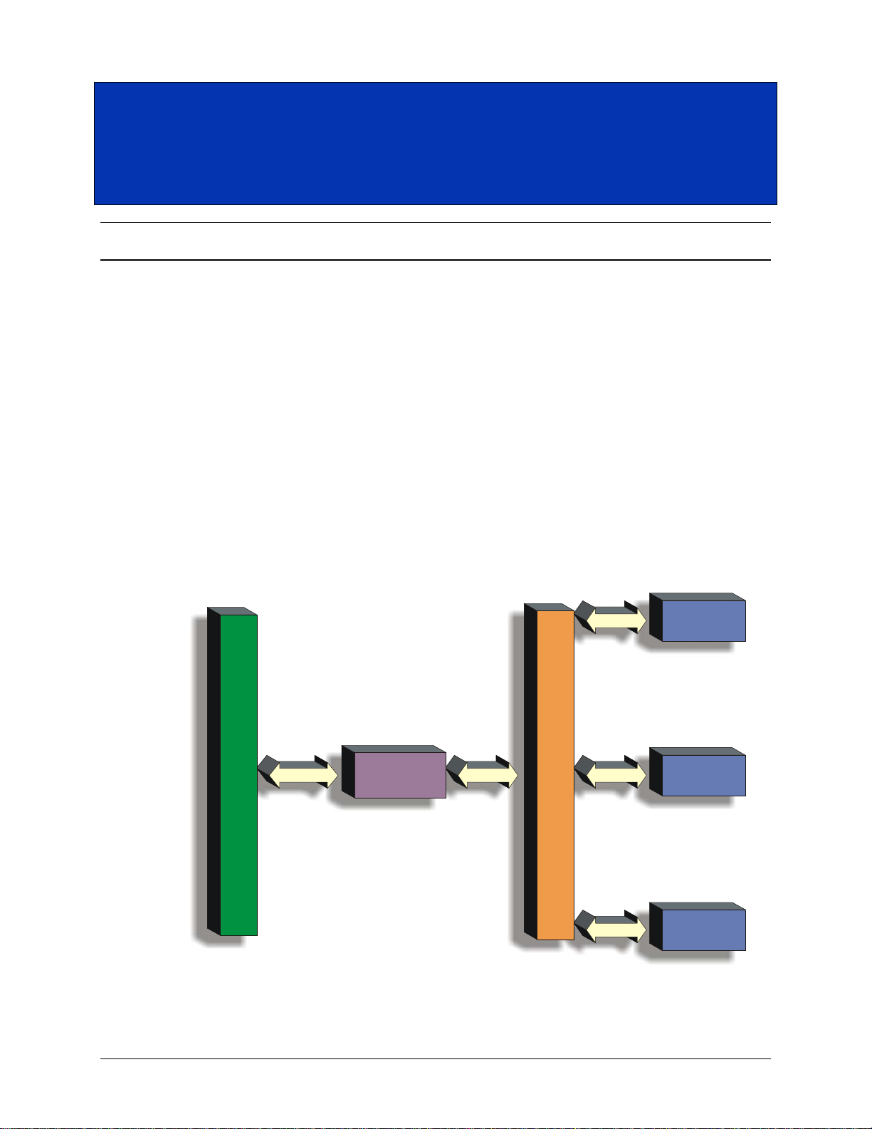
The VM2710A is a member of the VXI Technology VMIP (VXI Modular Instrumentation
Platform) family. This gives the user the added flexibility of combining it with other instruments,
such as arbitrary waveform generators or digitizers, to create a multi-function C-size card. Finally,
users do not need to take up a complete VXIbus card slot for the DMM functionality required,
making the VM2710A the ideal choice for data acquisition and ATE. The VM2710A may be
combined with any of the other members of the VMIP family to form a customized and highly
integrated instrument (see Figure 1-1). This allows the user to reduce system size and cost by
combining the VM2710A with two other instrument functions in a single-wide C-size VXIbus
module.
FIGURE 1-1: VMIP
10 VM2710A Introduction
PLATFORM
Page 11
www.vtiinstruments.com
bus
FAIL
ACC/
ERR
FAIL
ACC/
ERR
FAIL
ACC/
ERR
J200
J201
J202
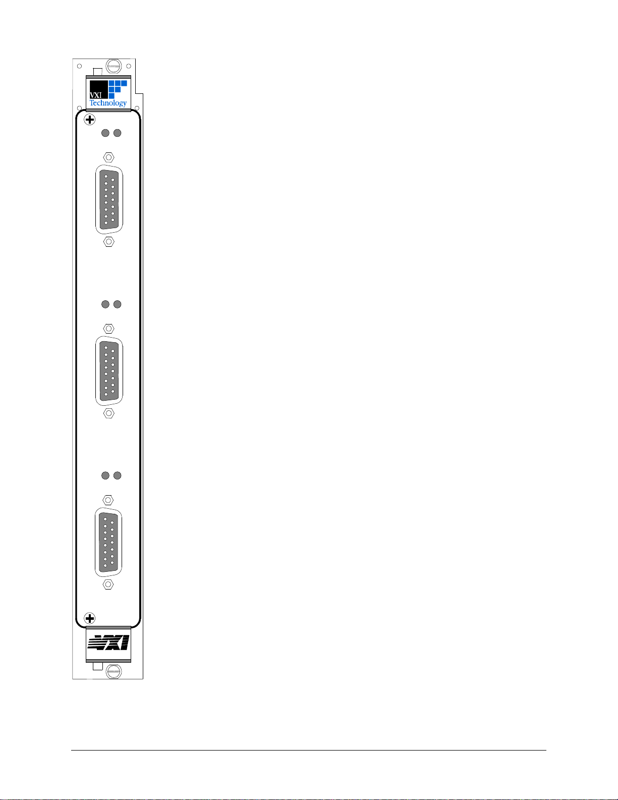
Regardless of whether the VM2710A is configured with other VM2710A modules or with
other VMIP modules, each DMM is treated as an independent instrument in the VXIbus
chassis. Each has its own Unique Logical Address and, as such, its own front panel FAIL and
ACCESS indicators.
DESCRIPTION
The VM2710A is designed for fast system throughput with greater than 2000 readings/s across
the backplane. For applications that require multiple input monitoring, the VM27 10 A pr ovide s
for on-board limit checking and the optio n of generating VXIbus triggers if the input e xceeds
these limits. This approach further speeds system throughput by freeing up the VXIbus
controller and backplane from having to continuously monitor these limits.
As part of the VMIP family of instruments, the VM2710A can be combined with up to two
other modules to form a high-density VXIbus instrument that fully utilizes the capabilities of
the VMIP module.
Two differential isolated input channels are provided on the VM2710A to allow one channel to
be connected to a scanning multiplexer while the other can be brought directly out for manual
testing or precision measurements.
Measurement aperture times may be programmed allowing the choice of resolution, accuracy,
and noise rejection (i.e., rejection of 50 Hz or 60 Hz noise). Fast function/range changes allow
for optimum measurement throughput. Short aperture times give high-speed readings while
longer aperture times give greater accuracy.
The DMM has extensive triggering capabilities including programmable delays to allow
synchronization with external devices. It can be triggered from the fr ont panel trigge r input, the
VXIbus trigge r lines or via word-serial p r otocol.
The VM2710A is programmed using message-based, word serial protocol. The commands are
SCPI and IEEE STD 488.2 compatible. VXIplug&play drivers are also provided to further
ease programming.
The calibration constants are stored in non-volatile memory and are password protected for
security. These constants are determined when the instrument is calibrated and can be changed
as necessary (such as during routine calibration cycles). These constants may also be examined
at any time via a word serial query and altered via a word serial command. All calibration is
done via software , i ncl udi ng the ac range. This allows for automated calibration and eliminates
the need for removing covers from the unit.
FIGURE 1-2: FRONT PANEL LAYOUT
VM2710A Introduction 11
Page 12

VTI Instruments Corporation
GENERAL SPECIFICATIONS
WARM UP TIME
60 min
DMM INPUTS
Connector
15-Pin “D” Connector
INPUT HI, INPUT LO, +I, -I, GUARD, TRIGGER INPUT and/or GROUND
MEASUREMENT FUNCTIONS
Volts (dc, rms ac)
Current (dc, rms ac)
OTHER FRONT PANEL FEATURES
2 A fuse for current function
DATA ACCESS TYPES
Register or message-based word serial
MEMORY
64,000 readings / 256,000 readings optional
CALIBRATION METHOD
Programmable with covers on; calibration constants stored in non-volatile memory
OVERLOAD INDICATION
Programmable
AUTORANGING
Up-Ranges
@ > 120% of range in dc volts, ac volts and current functions
@ < 9% of range in ohms function
FILTERS
AC filter only
MAXIMUM COMMON MODE VOLTAGE
350 V dc or rms ac (500 V p)
OPERATING ENVIRONMENT
0 °C to 55 °C
VM2710A SPECIFICATIONS
Input Sets
Down-Ranges
Two input sets consisting of:
2-wire ohms
4-wire ohms
@ > 100% of range in ohms function
@ < 10% of range in dc volts, ac volts and current functions
12 VM2710A Introduction
Page 13
www.vtiinstruments.com
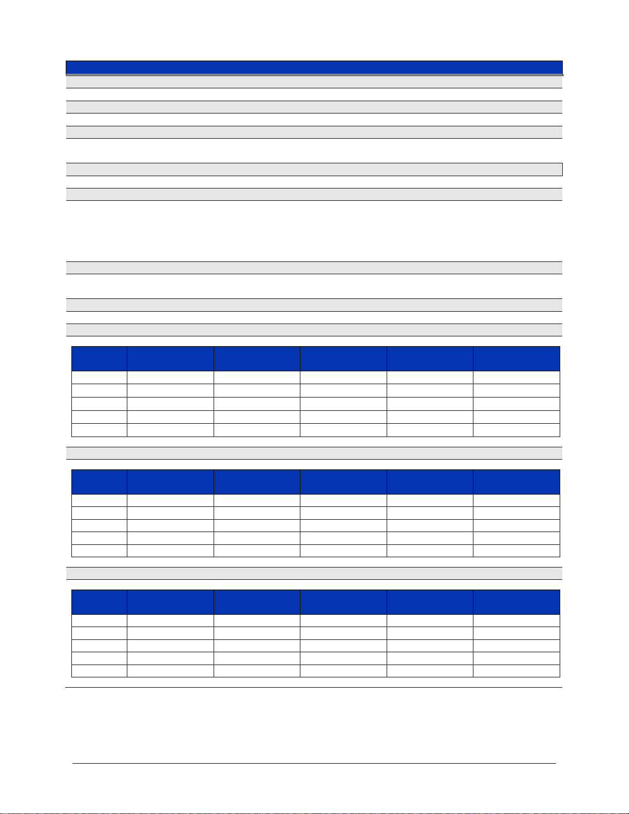
DC VOLTAGE SPECIFICATIONS
DC RANGES
0.1, 1.0, 10.0, 100.0, 300.0 V
OVER-RANGE
20% except 300 V range
INPUT IMPEDANCE
0.1 V – 10.0 V Range
100 V & 300 V Range
1.0 GΩ
10.0 MΩ
NORMAL MODE REJECTION @ POWER-LINE FREQUENCY ±0.1%, @ 100, 10 OR 1 PLC
> 70 dB
COMMON-MODE REJECTION, WITH UP TO 1 kΩ IN INPUT LOW LEAD
DC
0.03 PLC
> 140 dB
> 70 dB
INPUT BIAS CURRENT
At 23 °C
Over Temperature
50 PA maximum
100 PA maximum
INPUT PROTECTION
300 V on all ranges
RESOLUTION
100 PLC
(6.5 Digits)
10 PLC
(6.5 Digits)
1 PLC
(5.5 Digits)
0.1 PLC
(5.5 Digits)
0.03 PLC
(4.5 Digits)
0.1 V
100 nV
100 nV
1 µV
1 µV
10 µV
1.0 V
1 µV
1 µV
10 µV
10 µV
100 µV
10.0 V
10 µV
10 µV
100 µV
100 µV
1 mV
100.0 V
100 µV
100 µV
1 mV
1 mV
10 mV
300.0 V
100 µV
100 µV
1 mV
1 mV
10 mV
24 HR ACCURACY ± (%READING + %RANGE) T
CAL
±1 °C AFTER 1 HR WARM-UP
100 PLC
(6.5 Digits)
10 PLC
(6.5 Digits)
1 PLC
(5.5 Digits)
0.1 PLC
(5.5 Digits)
0.03 PLC
(4.5 Digits)
0.1 V
0.001 + 0.002
0.001 + 0.002
0.001 + 0.002
0.001 + 0.005
0.01 + 0.01
1.0 V
0.001 + 0.001
0.001 + 0.001
0.001 + 0.001
0.001 + 0.003
0.01 + 0.01
10.0 V
0.001 + 0.001
0.001 + 0.001
0.001 + 0.001
0.001 + 0.003
0.01 + 0.01
100.0 V
0.001 + 0.001
0.001 + 0.001
0.001 + 0.001
0.001 + 0.003
0.01 + 0.01
300.0 V
0.001 + 0.001
0.001 + 0.001
0.001 + 0.001
0.001 + 0.001
0.01 + 0.01
90 DAY ACCURACY ± (%READING + %RANGE) T
CAL
±5 °C AFTER 1 HR WARM-UP AND DC ZERO COMMAND
100 PLC
(6.5 Digits)
10 PLC
(6.5 Digits)
1 PLC
(5.5 Digits)
0.1 PLC
(5.5 Digits)
0.03 PLC
(4.5 Digits)
0.1 V
0.005 + 0.003
0.005 + 0.003
0.005 + 0.003
0.005 + 0.007
0.02 + 0.02
1.0 V
0.004 + 0.003
0.004 + 0.003
0.004 + 0.003
0.004 + 0.005
0.02 + 0.02
10.0 V
0.005 + 0.003
0.005 + 0.003
0.005 + 0.003
0.005 + 0.005
0.02 + 0.02
100.0 V
0.005 + 0.003
0.005 + 0.003
0.005 + 0.003
0.007 + 0.005
0.02 + 0.02
300.0 V
0.005 + 0.003
0.005 + 0.003
0.005 + 0.003
0.007 + 0.004
0.02 + 0.02
50 – 400 Hz @:
1, 10, 100 PLC
0.1 PLC
Range
Range
> 120 dB
> 80 dB
Range
VM2710A Introduction 13
Page 14
VTI Instruments Corporation
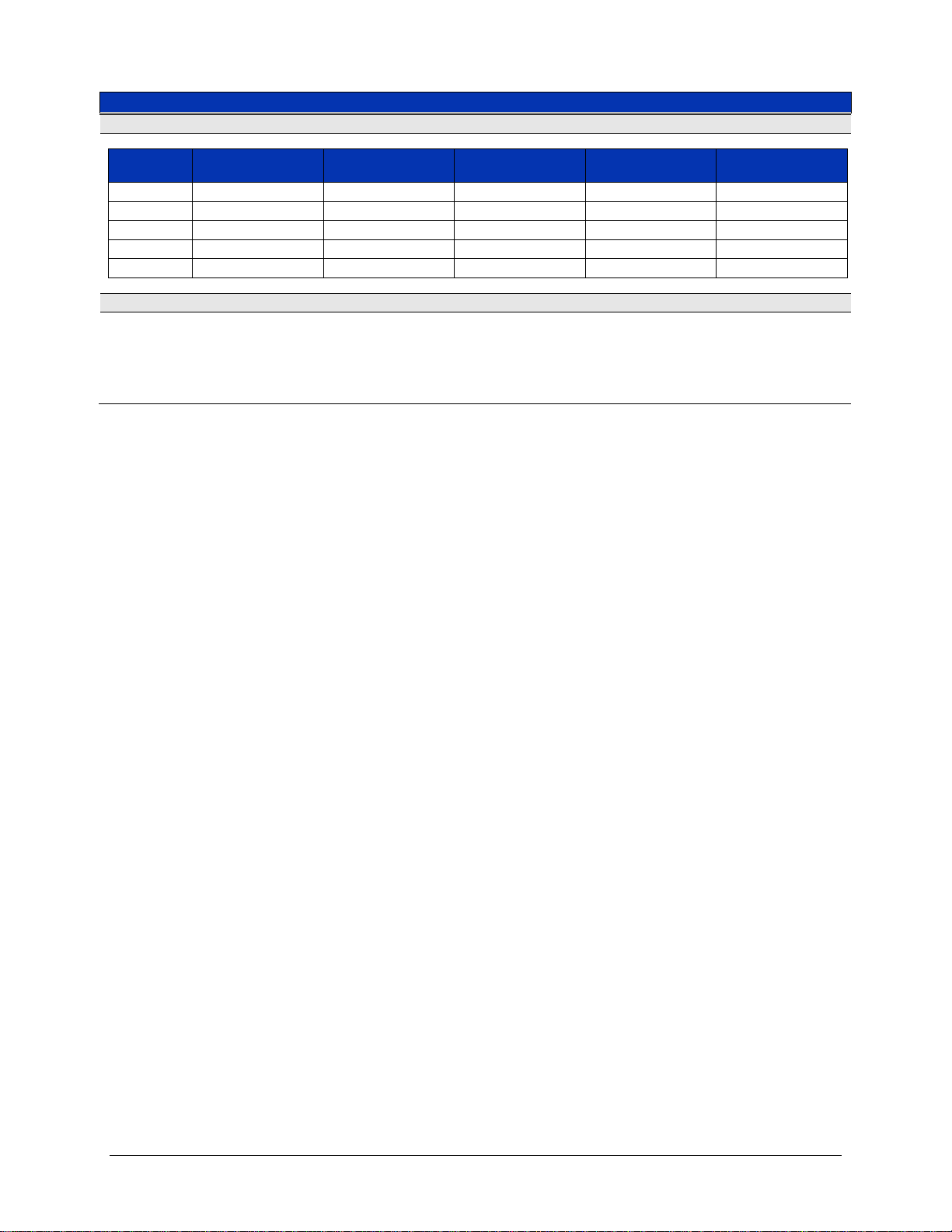
DC VOLTAGE SPECIFICATIONS (CONTINUED)
1 YEAR ACCURACY ± (%READING + %RANGE) T
CAL
± 5 °C AFTER 1 HOUR WARM-UP AND DC ZERO COMMAND
100 PLC
(6.5 Digits)
10 PLC
(6.5 Digits)
1 PLC
(5.5 Digits)
0.1 PLC
(5.5 Digits)
0.03 PLC
(4.5 Digits)
0.1 V
0.007 + 0.005
0.007 + 0.005
0.007 + 0.005
0.007 + 0.009
0.03 + 0.02
1.0 V
0.005 + 0.005
0.005 + 0.005
0.005 + 0.005
0.005 + 0.007
0.03 + 0.02
10.0 V
0.007 + 0.005
0.007 + 0.005
0.007 + 0.005
0.007 + 0.007
0.03 + 0.02
100.0 V
0.008 + 0.005
0.008 + 0.005
0.008 + 0.005
0.010 + 0.007
0.03 + 0.02
300.0 V
0.008 + 0.005
0.008 + 0.005
0.008 + 0.005
0.010 + 0.006
0.03 + 0.02
TEMPERATURE COEFFICIENT: 0 °C - 18 °C AND 28 °C - 55 °C; ±(%READING + %RANGE) / °C
0.1 V
300.0 V
0.0003 + 0.0005
0.0007 + 0.0001
Range
1.0 V
10.0
100.0
V
V
0.0002 + 0.0001
0.0003 + 0.0001
0.0007 + 0.0001
14 VM2710A Introduction
Page 15
www.vtiinstruments.com
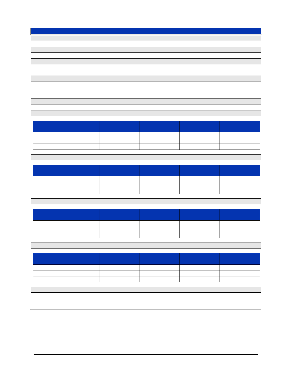
DC CURRENT SPECIFICATIONS
CURRENT RANGES
10 mA, 100 mA, and 1.0 A
OVER-RANGE
20% on all r anges
SHUNT RESISTORS
1.0 A Range
10 mA, 100 mA Range
0.1 Ω
8.1 Ω
BURDEN VOLTAGE
10 mA
1.0 A
≤ 100 mV
≤ 120 mV
OVERCURRENT PROTECTION
2.0 A fuse
RESOLUTION
100 PLC
(6.5 Digis)
10 PLC
(6.5 Digits)
1 PLC
(5.5 Digits)
0.1 PLC
(5.5 Digits)
0.03 PLC
(4.5 Digits)
10 mA
10 nA
10 nA
100 nA
100 nA
1 µA
100 mA
100 nA
100 nA
1 µA
1 µA
10 µA
1.0 A
1 µA
1 µA
10 µA
10 µA
100 µA
24 HOUR ACCURACY ±(%READING + %RANGE) T
CAL
±1 °C AFTER 1 HR WARM-UP
100 PLC
(6.5 Digits)
10 PLC
(6.5 Digits)
1 PLC
(5.5 Digits)
0.1 PLC
(5.5 Digits)
0.03 PLC
(4.5 Digits)
10 mA
0.005 + 0.005
0.005 + 0.005
0.005 + 0.005
0.005 + 0.005
0.010 + 0.010
100 mA
0.005 + 0.001
0.005 + 0.001
0.005 + 0.001
0.005 + 0.005
0.010 + 0.010
1.0 A
0.005 + 0.005
0.005 + 0.005
0.005 + 0.005
0.005 + 0.005
0.010 + 0.010
90 DAY ACCURACY ±(%READING + %RANGE) T
CAL
±5 °C AFTER 1 HR WARM-UP AND DC ZERO COMMAND
100 PLC
(6.5 Digits)
10 PLC
(6.5 Digits)
1 PLC
(5.5 Digits)
0.1 PLC
(5.5 Digits)
0.03 PLC
(4.5 Digits)
10 mA
0.015 + 0.010
0.015 + 0.010
0.015 + 0.010
0.015 + 0.010
0.030 + 0.050
100 mA
0.015 + 0.004
0.015 + 0.004
0.015 + 0.004
0.015 + 0.004
0.030 + 0.030
1.0 A
0.015 + 0.010
0.015 + 0.010
0.015 + 0.010
0.015 + 0.010
0.030 + 0.050
1 YEAR ACCURACY ±(%READING + %RANGE) T
CAL
±5 °C AFTER 1 HR WARM-UP
100 PLC
(6.5 Digits)
10 PLC
(6.5 Digits)
1 PLC
(5.5 Digits)
0.1 PLC
(5.5 Digits)
0.03 PLC
(4.5 Digits)
10 mA
0.020 + 0.015
0.020 + 0.015
0.020 + 0.015
0.020 + 0.015
0.05 + 0.05
100 mA
0.020 + 0.008
0.020 + 0.008
0.020 + 0.008
0.020 + 0.01
0.05 + 0.05
1.0 A
0.020 + 0.015
0.020 + 0.015
0.020 + 0.015
0.020 + 0.015
0.05 + 0.05
TEMPERATURE COEFFICIENT: 0 °C - 18 °C AND 28 °C - 55 °C; (%READING + %RANGE) / °C
10 mA
1.0 A
0.002 + 0.0005
0.002 + 0.0005
100 mA
Range
Range
Range
≤ 1.0 V
Range
100 mA
0.001 + 0.0005
VM2710A Introduction 15
Page 16
VTI Instruments Corporation
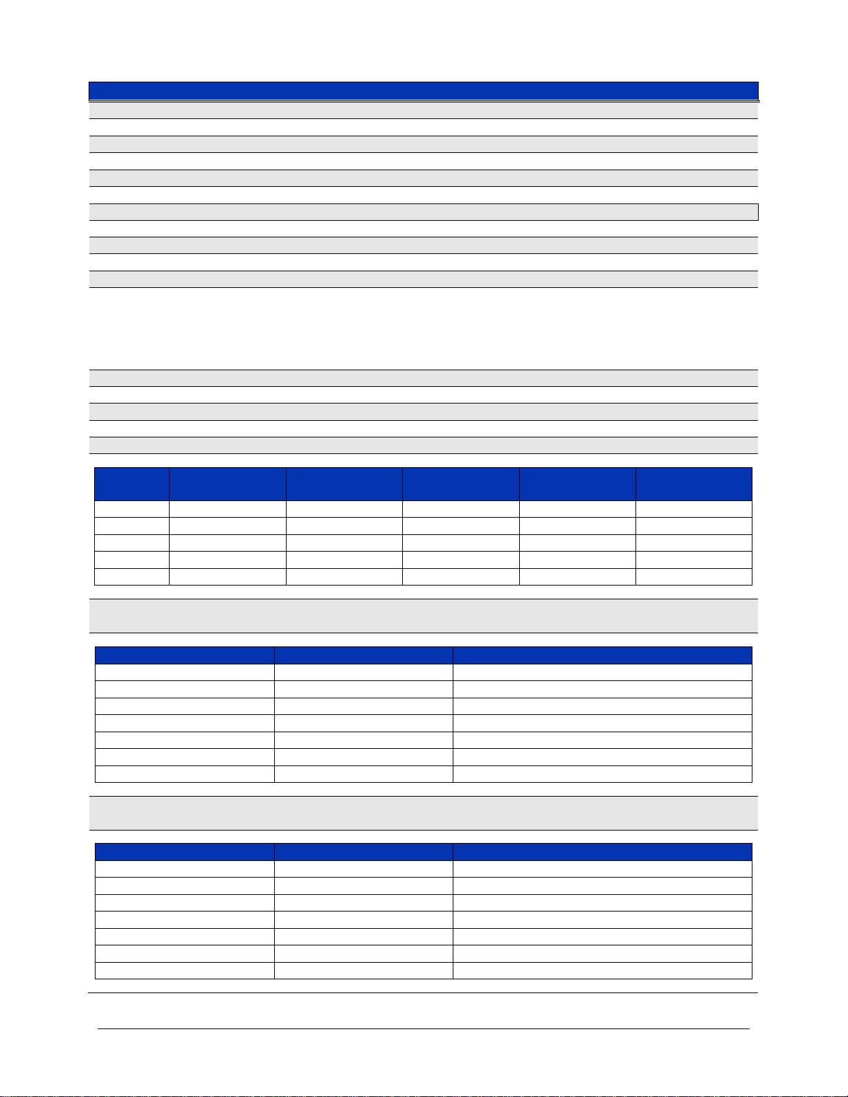
AC VOLTAGE SPECIFICATIONS
MEASUREMENT METHOD
AC-coupled true rms
AC RANGES
0.1, 1.0, 10.0, 100.0, 300.0 VAC
OVERRANGE
20% except 300 V range
INPUT IMPEDANCE
1 MΩ in parallel with < 50 pF
CREST FACTOR
5:1 maximum
ADDITIONAL CREST FACTOR ERROR
Crest Factor
4 - 5
Add 0.40% of reading
AC COMMON-MODE REJECTION WITH 100 Ω IN LOW LEAD
70 dB
MAXIMUM INPUT VOLTAGE
dc + ac = 300 V
rms
RESOLUTION
100 PLC
(6.5 Digits)
10 PLC
(6.5 Digits)
1 PLC
(5.5 Digits)
0.1 PLC
(5.5 Digits)
0.03 PLC
(4.5 Digits)
0.1 V
1 µV
1 µV
1 µV
10 µV
10 µV
1.0 V
10 µV
10 µV
10 µV
100 µV
100 µ
10.0 V
100 µV
100 µV
100 µV
1 mV
1 mV
100.0 V
1 mV
1 mV
1 mV
10 mV
10 mV
300.0 V
1 mV
1 mV
1 mV
10 mV
10 mV
A
100, 10,
PLC
T
±(%R
):
SINE-WAVE INPUT ≥ 5% FULL SCALE (F.S.), LOW-FREQUENCY FILTER ON
Range
0.1 V Range
1.0 V – 300.0 V Ranges : (VIN x Freq. ≤ 1.5x10⁷)
20 Hz – 30 Hz
1.00 + 0.15
1.00 + 0.02
30 Hz – 50 Hz
0.50 + 0.15
0.50 + 0.02
50 Hz – 200 Hz
0.20 + 0.15
0.20 + 0.02
200 Hz – 10 kHz
0.05 + 0.15
0.02 + 0.02
10 kHz – 50 kHz
0.20 + 0.15
0.05 + 0.04
50 kHz – 100 kHz
0.60 + 0.20
0.30 + 0.10
100 kHz – 300 kHz
3.00 + 0.50
3.00 + 0.50
A
100, 10
PLC
T
±(%R
):
SINE-WAVE INPUT ≥ 5% F.S., LOW-FREQUENCY FILTER ON
Range
0.1 V Range
1.0 V – 300.0 V Ranges : (VIN x Freq. ≤ 1.5x10⁷)
20 Hz – 30 Hz
1.10 + 0.15
1.10 + 0.03
30 Hz – 50 Hz
0.55 + 0.15
0.55 + 0.03
50 Hz – 200 Hz
0.23 + 0.15
0.23 + 0.03
200 Hz – 10 kHz
0.08 + 0.15
0.05 + 0.03
10 kHz – 50 kHz
0.23 + 0.15
0.10 + 0.05
50 kHz – 100 kHz
0.70 + 0.25
0.40 + 0.15
100 kHz – 300 kHz
4.00 + 0.60
4.00 + 0.60
1 - 2
2 - 3
3 - 4
Range
CCURACY @
Add 0.05% of reading
Add 0.15% of reading
Add 0.30% of reading
AND 1
FOR 24 HR @
±1 °C AFTER 1 HR WARM-UP;
CAL
EADING + %RANGE
CCURACY @
AND 1
FOR 90 DAYS @
±5 °C AFTER 1 HR WARM-UP;
CAL
16 VM2710A Introduction
EADING + %RANGE
Page 17
www.vtiinstruments.com
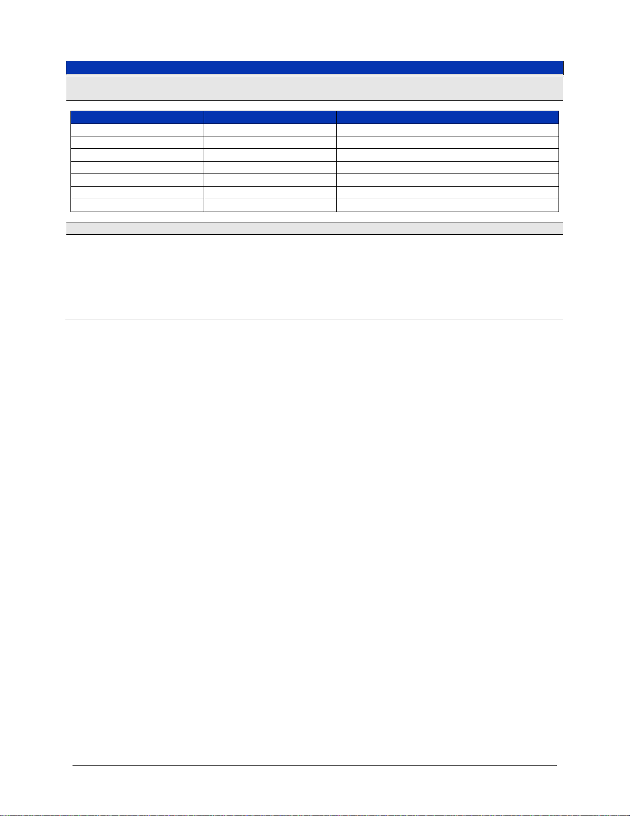
AC VOLTAGE SPECIFICATIONS (CONTINUED)
A
100, 10
PLC
T
±(%R
):
SINE-WAVE INPUT ≥ 5% F.S., LOW-FREQUENCY FILTER ON
Range
0.1 V Range
1.0 V – 300.0 V Ranges : (VIN x Freq. ≤ 1.5x10⁷)
20 Hz – 30 Hz
1.12 + 0.15
1.12 + 0.04
30 Hz – 50 Hz
0.57 + 0.15
0.57 + 0.04
50 Hz – 200 Hz
0.25 + 0.15
0.25 + 0.04
200 Hz – 10 kHz
0.10 + 0.15
0.07 + 0.04
10 kHz – 50 kHz
0.25 + 0.15
0.12 + 0.06
50 kHz – 100 kHz
0.75 + 0.25
0.45 + 0.20
100 kHz – 300 kHz
4.00 + 0.60
4.00 + 0.60
TEMPERATURE COEFFICIENT; 0 °C - 18 °C AND 28 °C - 55 °C; ±(%READING + %RANGE) / °C
20 Hz – 30 Hz
50 kHz – 100 kHz
0.020 + 0.001
0.020 + 0.010
Note: Add 0.005% Reading/°C in 100.0 V and 300.0 V ranges
CCURACY @
30 Hz – 50 Hz
50 Hz – 200 Hz
200 Hz – 10 kHz
10 kHz – 50 kHz
AND 1
FOR 1 YR @
0.010 + 0.001
0.005 + 0.001
0.005 + 0.001
0.005 + 0.001
±5 °C AFTER 1-HR WARM-UP;
CAL
EADING + %RANGE
VM2710A Introduction 17
Page 18
VTI Instruments Corporation
AC CURRENT SPECIFICATIONS
MEASUREMENT METHOD
Direct coupled to fuse and shunt, ac-coupled true rms measurement
CURRENT RANGES
10 mA, 100 mA, and 1.0 A rms
OVER-RANGE
20%
SHUNT RESISTORS
1.0 A Range
10 mA & 100 mA Range
0.1 Ω
8.1 Ω
BURDEN VOLTAGE
10 mA
1.0 A
≤ 100 mV
≤ 120 mV
OVER-CURRENT PROTECTION
2.0 A fuse
RESOLUTION
100 PLC
(6.5 Digits)
10 PLC
(6.5 Digits)
1 PLC
(5.5 Digits)
0.1 PLC
(5.5 Digits)
0.03 PLC
(4.5 Digits)
10 mA
100 nA
100 nA
1 µA
1 µA
1 µA
100 mA
1 µA
1 µA
1 µA
10 µA
10 µA
1.0A
10 µA
10 µA
10 µA
100 µA
100 µA
24 HR ACCURACY1
Range
10 mA Range
100 mA Range
1.0 A Range
20 Hz – 30 Hz
1.00 + 0.20
1.00 + 0.04
1.00 + 0.20
30 Hz – 50 Hz
0.50 + 0.20
0.50 + 0.04
0.50 + 0.20
50 Hz – 1k Hz
0.20 + 0.20
0.20 + 0.04
0.20 + 0.20
1k Hz – 5kHz
0.17 + 0.20
0.17 + 0.20
0.17 + 0.20
5kHz – 10kHz
0.55 + 0.30
0.55 + 0.30
3.0 + 0.30
90 DAY ACCURACY2
Range
10 mA Range
100 mA Range
1.0 A Range
20 Hz – 30 Hz
1.10 + 0.20
1.10 + 0.05
1.10 + 0.20
30 Hz – 50 Hz
0.60 + 0.20
0.60 + 0.05
0.60 + 0.20
50 Hz – 1kHz
0.30 + 0.20
0.30 + 0.05
0.30 + 0.20
1kHz – 5kHz
0.27 + 0.20
0.27 + 0.20
0.27 + 0.20
5kHz – 10kHz
0.65 + 0.30
0.65 + 0.30
3.1 + 0.30
1 YR ACCURACY2
Range
10 mA Range
100 mA Range
1.0 A Range
20 Hz – 30 Hz
1.12 + 0.20
1.12 + 0.06
1.12 + 0.20
30 Hz – 50 Hz
0.62 + 0.20
0.62 + 0.06
0.62 + 0.20
50 Hz – 1kHz
0.32 + 0.20
0.32 + 0.06
0.32 + 0.20
1kHz – 5kHz
0.29 + 0.20
0.29 + 0.20
0.29 + 0.20
5kHz – 10kHz
0.67 + 0.30
0.67 + 0.30
3.12 + 0.30
TEMPERATURE COEFFICIENT: 0 °C - 18 °C AND 28 °C - 55 °C; (%READING + %RANGE) / °C
20 Hz – 30 Hz
50 Hz – 10kHz
0.020 + 0.001
0.006 + 0.001
100 mA
Range
≤ 1.0 V
30 Hz – 50 Hz
0.010 + 0.001
18 VM2710A Introduction
Page 19
www.vtiinstruments.com
RESISTANCE SPECIFICATIONS
RESISTANCE RANGES
20 Ω, 200 Ω, 2 kΩ, 20 kΩ, 200 kΩ, 2 MΩ, 20 MΩ
OVER-RANGE
None
VOLTAGE ACROSS UNKNOWN
20 Ω & 200 Ω Ranges
All Other Ranges
240 mV nominal at full scale
2.4 V nominal at full scale
LEAD WIRE RESISTANCE
20 Ω & 200 Ω Ranges
All Other Ranges
10.0 Ω maximum
100.0 Ω maximum
VOLTAGE PROTECTION
300 V dc or peak ac
OPEN CIRCUIT VOLTAGE
20 Ω & 200 Ω Ranges
2 kΩ & 20 MΩ Ranges
+8 V max. in 20 Ω and 200 Ω range
+9 V max. in 2 kΩ and 20 MΩ range
MEASUREMENTCURRENTS
Range
20 MΩ
Current
120 nA
RESOLUTION
100 PLC
(6.5 Digits)
10 PLC
(6.5 Digits)
1 PLC
(5.5 Digits)
0.1 PLC
(5.5 Digits)
0.03 PLC
(4.5 Digits)
20 Ω
100 µΩ
100 µΩ
100 µΩ
1 mΩ
1 mΩ
200 Ω
100 µΩ
1 mΩ
1 mΩ
10 mΩ
10 mΩ
2 kΩ
1 mΩ
1 mΩ
10 mΩ
100 mΩ
100 mΩ
20 kΩ
10 mΩ
10 mΩ
100 mΩ
1.0 Ω
1.0 Ω
200 kΩ
100 mΩ
100 mΩ
1.0 Ω
10 Ω
10 Ω
2 MΩ
1.0 Ω
1.0 Ω
10 Ω
100 Ω
100 Ω
20 MΩ
100 Ω
100 Ω
1 kΩ
1 kΩ
1 kΩ
4-WIRE - 24 HOUR ACCURACY ± (%READING + %RANGE) T
CAL
±1 °C AFTER 1 HOUR WARM-UP
3
Range
100 PLC
10 PLC
1 PLC
0.1 PLC
0.03 PLC
20 Ω
0.001 + 0.007
0.001 + 0.007
0.001 + 0.007
0.001 + 0.007
0.01 + 0.02
200 Ω
0.001 + 0.007
0.001 + 0.007
0.001 + 0.007
0.001 + 0.007
0.01 + 0.02
2 kΩ
0.001 + 0.001
0.001 + 0.001
0.001 + 0.003
0.001 + 0.005
0.01 + 0.02
20 kΩ
0.001 + 0.002
0.001 + 0.002
0.001 + 0.003
0.001 + 0.005
0.01 + 0.02
200 kΩ
0.001 + 0.002
0.001 + 0.002
0.001 + 0.003
0.001 + 0.005
0.01 + 0.02
2 MΩ
0.001 + 0.002
0.001 + 0.002
0.001 + 0.003
0.040 + 0.005
0.03 + 0.02
20 MΩ
0.010 + 0.002
0.010 + 0.002
0.010 + 0.003
0.200 + 0.005
0.20 + 0.02
20 Ω
200 Ω
2 kΩ
20 kΩ
200 kΩ
2 MΩ
Range
12 mA
1.2 mA
1.2 mA
100 µA
12 µA
1.2 µA
VM2710A Introduction 19
Page 20
VTI Instruments Corporation
RESISTANCE SPECIFICATIONS (CONTINUED)
4-W
±(%R
T
CAL
3
Range
100 PLC
10 PLC
1 PLC
0.1 PLC
0.03 PLC
20 Ω
0.005 + 0.008
0.005 + 0.008
0.005 + 0.008
0.005 + 0.010
0.02 + 0.02
200 Ω
0.005 + 0.008
0.007 + 0.008
0.007 + 0.008
0.007 + 0.010
0.02 + 0.02
2 kΩ
0.005 + 0.002
0.007 + 0.003
0.007 + 0.005
0.007 + 0.007
0.02 + 0.02
20 kΩ
0.005 + 0.003
0.007 + 0.003
0.007 + 0.005
0.007 + 0.007
0.02 + 0.02
200 kΩ
0.005 + 0.003
0.007 + 0.003
0.007 + 0.005
0.007 + 0.007
0.02 + 0.02
2 MΩ
0.010 + 0.003
0.010 + 0.003
0.010 + 0.005
0.050 + 0.007
0.04 + 0.03
20 MΩ
0.020 + 0.003
0.020 + 0.003
0.020 + 0.005
0.200 + 0.007
0.20 + 0.05
4-WIRE: 1 YR ACCURACY ±(%READING + %RANGE) T
CAL
±5 °C AFTER 1 HR WARM-UP
3
Range
100 PLC
10 PLC
1 PLC
0.1 PLC
0.03 PLC
20 Ω
0.010 + 0.010
0.010 + 0.010
0.010 + 0.010
0.010 + 0.015
0.03 + 0.03
200 Ω
0.010 + 0.010
0.010 + 0.010
0.010 + 0.010
0.010 + 0.010
0.03 + 0.03
2 kΩ
0.010 + 0.005
0.010 + 0.005
0.010 + 0.007
0.010 + 0.007
0.03 + 0.03
20 kΩ
0.010 + 0.005
0.010 + 0.005
0.010 + 0.007
0.010 + 0.007
0.03 + 0.03
200 kΩ
0.010 + 0.005
0.010 + 0.005
0.010 + 0.007
0.010 + 0.007
0.03 + 0.03
2 MΩ
0.015 + 0.005
0.015 + 0.005
0.015 + 0.010
0.060 + 0.010
0.05 + 0.04
20 MΩ
0.025 + 0.005
0.025 + 0.005
0.025 + 0.010
0.210 + 0.010
0.22 + 0.05
TEMPERATURE COEFFICIENT; 0 °C - 18 °C AND 28 °C - 55 °C; ±(%READING + %RANGE) / °C
Range
20 MΩ
0.0035 + 0.0004
READING RATE SPECIFICATIONS
RESISTANCE RANGES
Read Rates (60 Hz)
Aperture Times
100 PLC 10 PLC 1 PLC 0.1 PLC 0.03 PLC
IRE: 90 DAY ACCURACY
20 Ω
200 Ω
2 kΩ
20 kΩ
200 kΩ
2 MΩ
EADING + %RANGE)
0.0007 + 0.0002
0.0007 + 0.0002
0.0006 + 0.0001
0.0006 + 0.0002
0.0006 + 0.0002
0.0015 + 0.0004
±5 °C AFTER 1 HR WARM-UP
Readings/s
Aperture Times
Read Rates (70 Hz)
Readings/s
Note
1
Accuracy @ 100, 10 and 1 PLC @ T
2
Accuracy @ 100, 10 and 1 PLC @ T
3
2-wire accuracy is the same as that shown for 4-wire measurements after performing a math null measurement. Without setting the null, readings will
include lead resistance, which is application specific, and add 0.2 Ω of additional error for contact resistance. Typical 24 AWG stranded wire is
0.03 Ω/ft.
0.5 5.0 50.0 500.0 2000.0
100 PLC 10 PLC 1 PLC 0.1 PLC 0.03 PLC
0.4 4.0 45.0 450.0 2000.0
±1 °C after 1 hr warm-up; ±(%Reading + %Range), Sine-wave input ≥ 5% F.S., Low-Frequency Filter ON
CAL
± 5 °C after 1 hr warm-up; ±(%Reading + %Range), Sine-wave input ≥ 5% F.S., Low-Frequency Filter ON
CAL
20 VM2710A Introduction
Page 21

www.vtiinstruments.com
SECTION 2
PREPARATION FOR USE
INSTALLATION
When the VM2710A is unpacked from its shipping carton, the contents should include the
following items:
(1) VM2710A VXIbus module
(1) VM2710A 6.5 Digit Multimeter User’s Manual (this manual)
All components should be immediately inspected for damage upon receipt of the unit.
Once the VM2710A is assessed to be in good condition, it may be installed into an appropriate
C-size or D-size VXIbus chassis in any slot other than slot zero. The chassis should be checked to
ensure that it is capable of providing adequate power and cooling for the VM2710A. Once the
chassis is found adequate, the VM2710A’s logical address and the chassis’ backplane jumpers
should be configured prior to the VM2710A’s installation.
CALCULATING SYSTEM POWER AND COOLING REQUIREMENTS
It is imperative that the chassis provide adequate power and cooling for this module. Referr ing to
the chassis user’s manual, confirm that the power budget for the system (the chassis and all
modules installed therein) is not exceeded and that the cooling system can provide adequate
airflow at the specified backpressure.
It should be noted that if the chassis cannot provide adequate power to the module, the instrument
may not perform to specification or possibly not operate at all. In addition, if adequate coo ling is
not provided, the reliability of the instrument will be jeopardized and permanent damage may
occur. Damage found to have occurred due to inadequate cooling would also void the warranty of
the module.
SETTING THE CHASSIS BACKPLANE JUMPERS
Please refer to the chassis operation manual for further details on setting the backplane jumpers.
VM2710A Preparation for Use 21
Page 22
VTI Instruments Corporation
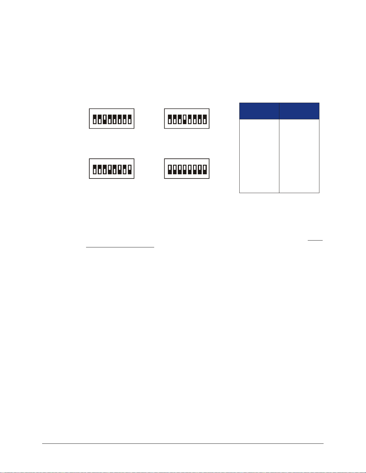
SET TO 4
1ON2 3 4 5 6 7 8
SET TO 168
1 2 3 4 5 6 7 8
SET TO 8
1ON2 3 4 5 6 7 8
SET TO 255
1
ON ON
2 3 4 5 6 7 8
1
2
3
4
5
6
7
8
Switch
Position
1
2
4
8
16
32
64
128
Switch
Value
ON ON
(Dynamic)
SETTING THE LOGICAL ADDRESS
The logical address of the VM2710A is set by a single 8-position DIP switch located near the
VMIP module’s backplane connectors (this is the only switch on the module). The switch is
labeled with positions 1 through 8 and with an ON position. A switch pushed toward the ON
legend will signify a logic 1; switches pushed away from the ON legend will signify a logic 0. The
switch located at position 1 is the least significant bit while the switch located at position 8 is the
most significant bit. See Figure 2-1 for examples of setting the logical address switch.
FIGURE 2-1: LOGICAL ADDRESS SWITCH SETTING EXAMPLES
The VMIP may contain three separate instruments and will allocate logical addresses as required
by the VXIbus specification (revisions 1.3 and 1.4). The logical address of the instrument is set on
the VMIP carrier. The VMIP logical addresses must be set to an even multiple of 4 unless
dynamic addressing is used. Switch positions 1 and 2 must always be set to the OFF position.
Therefore, only addresses of 4, 8, 12, 16, ... 252 are allowed. The address switch should be set for
one of these legal addresses and the address for the second instrument (the instrument in the center
position) will automatically be set to the switch set address plus one; while the third instrument
(the instrument in the lowest position) will automatically be set to the switch set address plus two.
If dynamic address configuration is desired, the address switch should be set for a value of 255
(All switches set to ON). Upon power-up, the slot 0 resource manager will assign the first
available logical addresses to each instrument in the VMIP module.
If dynamic address configuration is desired, the address switch should be set for a value of 255.
(All switches set to ON). Upon power-up, the slot 0 resource manager will assign the first
available logical addresses to each instrument in the VMIP module.
22 VM2710A Preparation for Use
Page 23
www.vtiinstruments.com
PIN NUMBER
SIGNAL
1
FRONT PANEL TRIGGER INPUT
2
GUARD CHAN B (Shield)
3
INPUT CHAN B LOW
4
INPUT CHAN B HIGH
5
GUARD CHAN B (Shield)
6
INPUT CHAN A LOW
7
INPUT CHAN A HIGH
8
GUARD CHAN A (Shield)
9
GROUND
10
GUARD CHAN B (Shield)
11
-I:
CHAN B (ac / dc current and 4-wire ohms)
12
+I:
CHAN B (ac / dc current and 4-wire ohms)
13
GUARD CHAN A (Shield)
14
-I:
CHAN A (ac / dc current and 4-wire ohms)
15
+I:
CHAN A (ac / dc current and 4-wire ohms)
9
15
8
1
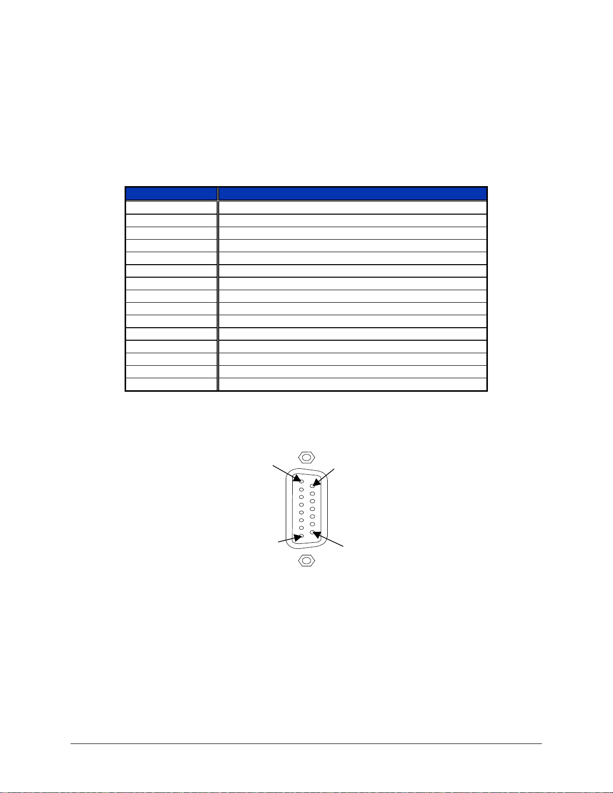
FRONT PANEL INTERFACE WIRING
The VM2710A’s interface is made available on the front panel of the instrument. The
VM2710A-1 will have J201 that contains all signals for this instrument. The VM2710A-2 will
have J201 and J202, while the VM2710A-3 will have J200, J201, and J202. The wiring for each
of these connectors is identical and since each group is treated as a separate instrument, the module
will have three A channels and three B channels.
TABLE 2-1: DIGIT MULTIMETER PIN OUTS
The pin locations for J200, J201, and J202 are shown in Figure 2-2:
FIGURE 2-2: J200, J201, AND J202 PIN LOCATIONS
VM2710A Preparation for Use 23
Page 24

VTI Instruments Corporation
SECTION 3
PROGRAMMING
INTRODUCTION
The VM2710A is a VXIbus message-based device whose command set is compliant with the
Standard Command for Programmable Instruments (SCPI) programming language.
All module commands are sent over the VXIbus backplane to the module. Commands may be in
upper, lower or mixed case. All numbers are sent in ASCII decimal unless otherwise noted.
The module recognizes SCPI commands. SCPI is a tree-structured language based on IEEE Std
488.2 Specifications. It utilizes the IEEE STD 488.2 Standard command, and the device
dependent commands are structured to allow multiple branches off the same trunk to be used
without repeating the trunk. To use this facility, terminate each branch with a semicolon. As an
example, DELay:AUTOmatic, SLOPe, and SOURce are all branches off the TRIGger: trunk
and can be combined as follows:
TRIGger:DELay:AUTOmatic;SLOPe POS;SOURce EXT
The above command is the same as the these three commands:
TRIGger:DELay:AUTOmatic
TRIGger:SLOPe POS
TRIGger:SOURce EXT
See the Standard Command for Programmable Instruments (SCPI) Manual, Volume 1: Syntax &
Style, Section 6 for more information.
The SCPI commands in this section are listed in upper and lower case. Character case is used to
indicate different forms of the same command. Keywords can have both a short form and a long
form (some commands only have one form). The short form uses just the keyword characters in
uppercase. The long form uses the keyword characters in uppercase plus the keyword characters in
lowercase. Either form is acceptable. Note that there are no intermediate forms. All characters of
the short form or all characters of the long form must be used. Short forms and long forms may be
freely intermixed. The actual commands sent can be in upper case, lower case or mixed case (case
is only used to distinguish short and long form for the use r). As an exa mple, these c ommands are
all correct and all have the same effect:
24 VM2710A Programming
Page 25

www.vtiinstruments.com
TRIGger:SOURce EXTernal
trigger:source external
TRIGGER:SOURCE EXTERNAL
TRIG:SOURce EXTernal
TRIG:SOUR EXTernal
TRIG:SOUR EXT
trig:sour EXT
trig:sour ext
The following co mmand is not correct because it uses part of the long form of TRIGger, but not
all the characters of the long form:
TRIGG:SOUR EXT (incorrect syntax - extra "G"- only trig or trigger is corre ct)
All of the SCPI commands also have a query form unless otherwise noted. Query forms contain a
question mark (?). The query form allows the system to ask what the current set ting of a parameter
is. The query form of the command generally replaces the parameter with a question mark (?).
Query responses do not include the command header. This means only the parameter is returned:
no part of the command or "question" is returned.
When character data is used for a parameter, both short and long forms are recognized. If the
command has a query form with character response data, the short form is always returned in upper
case. As an example, to find out what the current trigger source setting is use the following
command:
TRIG:SOUR?
The response would be:
EXT
This tells the user that the trigger is set to an external source.
Multiple commands can also be combined on one line. To do this, terminate one command with a
semicolon and start the next command with a colon. As an example, the trigger source can be set
to a positive edge and an output trigger line can be enabled as follows:
TRIG:SOUR EXT;:OUTPUT:TTLTRG1 ON
The IEEE-STD-488.2 Common Commands can be placed anywhere set off from the rest of the
command by a semicolon. They can also be placed alone on a line. For example, place the *RST
command in front of a setting string as follows:
*RST;OUTP:TTLT 3;POL POS
Note that the OUTP:TTLT comman d s et did not require a leading colon (:) because there was no
prior trunk of the SCPI tree.
VM2710A Programming 25
Page 26
VTI Instruments Corporation
NOTATION
Keywords or parameters enclosed in square brackets ([ ]) are optional. If the optional part is a
keyword, the keyword can be included or left out. Omitting an optional parameter will cause its
default to be used.
Parameters are enclosed by angle brackets (< >). Braces ({ }),or curly brackets, are used to
enclose one or more parameters that may be included zero or more times. A vertical bar (|), read
as "or", is used to separate parameter alternatives.
REGISTER ACCESS
The VM2710A provides pseudo register access for high-speed data retrieval. The register is read
only and has 32-bit information accessible in two 16-bit parts.
There are two methods for accessing the 32-bit information. One method is to access the
information as a 32-bit data value with data-high and data-low retrieved from two 16-bit locations.
The second method is 32-bit access from one 16-bit location with the data-high/data-low
information alternating (data-high is first). This second method of data retrieval must be properly
synchronized otherwise the data would all be offset by 16 bits. The register map is specified in
Table 3-2.
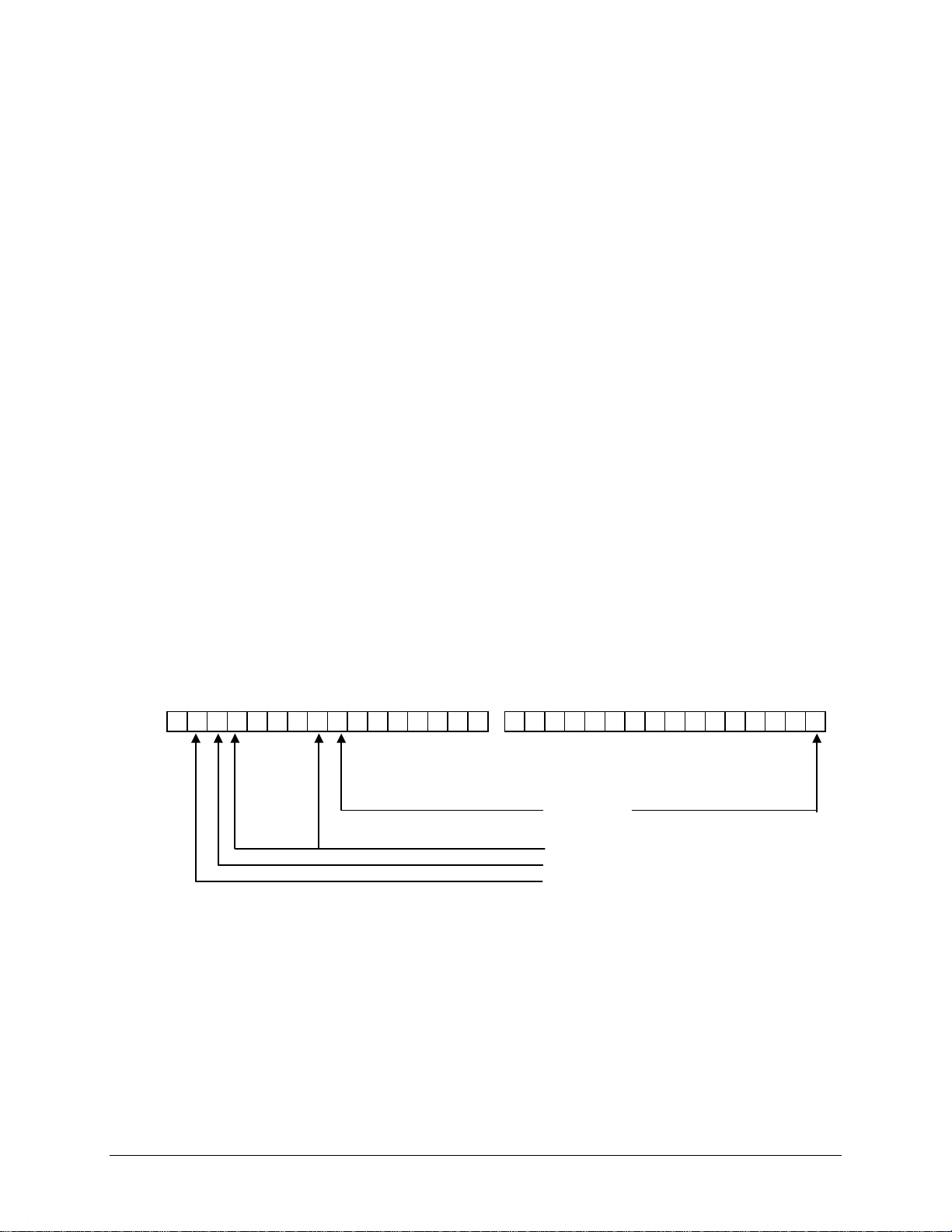
The eight most significant bits of data-high contain data status and instrument function
information. The eight LSB of data-high, along with all 16 bits of data-low, contain the data
collected. Figure 3-1 defines the 32 data bit assignments in the register. The instrument Function
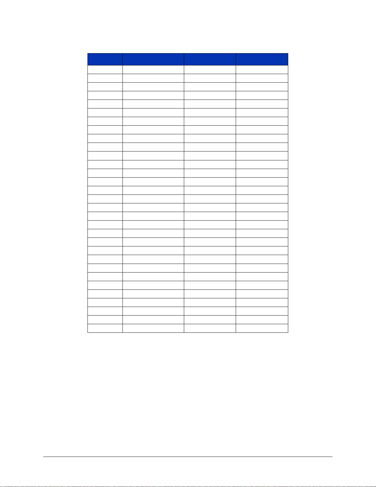
and Range informati on (bits 24 through 28) is defined in Table 3-1.
Data-High Data-Low
31 30 29 28 27 26 25 24 23 22 21 20 19 18 17 16 15 14 13 12 11 10 9 8 7 6 5 4 3 2 1 0
Raw Data
Function and Range
Negative Overflow
Positive Overflow
FIGURE 3-1: REGISTER ACCESS - 32-BIT
26 VM2710A Programming
Page 27
www.vtiinstruments.com
0
PON/Test
N/A
N/A 1 0.1 V dc
3.00000e-8
0x00400000
2
1.0 V dc
3.00000e-7
0x00400000
3
10 V dc
3.00000e-6
0x00400000
4
100 V dc
3.00000e-5
0x00400000
5
300 V dc
7.50000e-5
0x00400000
6
0.1 V ac
1.50000e-8
0x00000000
7
1.0 V ac
1.50000e-7
0x00000000
8
10 V ac
1.50000e-6
0x00000000
9
100 V ac
1.50000e-5
0x00000000
10
300 V ac
3.70000e-5
0x00000000
11
20 Ω
2.50000e-6
0x00000000
12
200 Ω
2.50000e-5
0x00000000
13
2 kΩ
2.50000e-4
0x00000000
14
20 kΩ
2.50000e-3
0x00000000
15
200 kΩ
2.50000e-2
0x00000000
16
2 MΩ
2.50000e-1
0x00000000
17
20 MΩ
2.50000e+0
0x00000000
18
20 4-Wire Ω
2.50000e-6
0x00000000
19
200 4-Wire Ω
2.50000e-5
0x00000000
20
2 k 4-Wire Ω
2.50000e-4
0x00000000
21
20 k 4-Wire Ω
2.50000e-3
0x00000000
22
200 k 4-Wire Ω
2.50000e-2
0x00000000
23
2 M 4-Wire Ω
2.50000e-1
0x00000000
24
20 M 4-Wire Ω
2.50000e+0
0x00000000
25
10 mA dc
3.00000e-9
0x00400000
26
100 mA dc
3.00000e-8
0x00400000
27
1 A dc
3.00000e-7
0x00400000
28
10 mA ac
1.50000e-9
0x00000000
29
100 mA ac
1.50000e-8
0x00000000
30
1 A ac
1.50000e-7
0x00000000
Value Function Scale Offset
TABLE 3-1: FUNCTION AND RANGE
VM2710A Programming 27
Page 28

VTI Instruments Corporation
Offset
Description
3E 3C 3A 38 36 34 32 30 2E
Write Pointer-Low
2C
Write Pointer-High
2A
Read Pointer-Low
28
Read Pointer-High
26
Data / 16-Bit
24
FIFO Status
22
Data-Low / 32-Bit
20
Data-High / 32-Bit
1E 1C 1A 18
16
[ A32 Pointer Low ]
14
[ A32 Point er High ]
12
[ A24 Pointer Low ]
10
[ A24 Point er High ]
E
Data Low
C
Data High
A
Response [ / Data Extended]
8
Protocol [ / Signal] Register
6
[Offset Register]
4
Status / Control Register
2
Device Type
0
ID Register
The VM2710A supports data access by way of the Device Dependent Registers of the VXIbus
interface. The following table shows A16 Memory and the VM2710A Data Map.
TABLE 3-2: READ ONLY REGISTERS - A16 ADDRESS SPACE
28 VM2710A Programming
Page 29
www.vtiinstruments.com
Not Used
Not Used
Not Used
Not Used
Not Used
Not Used
Not Used
1=FIFO is EMPTY / 0=FIFO is not EMPTY
1=FIFO is FULL / 0=FIFO is not FULL
1=Data underflow (the FIFO was read when no
1=Data overflow (data wasn't read out of the
DATA 16 high/low indicator
low 16 bits
FIFO size
is installed.
Hardware revision level
Hardware revision level
Hardware revision level
15 14 13 12 11 10 9 8 7 6 5 4 3 2 1 0
Bit Number
data was in the FIFO)
0=There hasn't been a data underflow
Once set, stays set until a *RST.
FIFO fast enough and the FIFO overflowed)
0=There hasn't been a F I FO overflow
Once set, stays set until a *RST.
1= Data read from the DATA 16 register is the
high 16 bits
0=Data read from the DATA 16 register is the
1 = 256 k readings deep
0 = 64 k readings deep
This bit depends on whether the optional RAM
VM2710A Programming 29
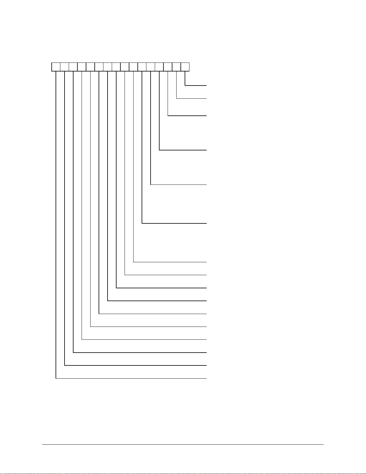
F
IGURE 3-2: FIFO STATUS REGISTER
Page 30

VTI Instruments Corporation
REGISTER ACCESS PROGRAMMING EXAMPLE
The following register access example includes parameter set-up, testing and data retrieval:
#include <utility.h>
#include <ansi_c.h>
#include <nivxi.h>
#include "stdio.h"
#include <userint.h>
#include "vxitech.h"
static double volt, voltmin, voltmax, accumulate;
static char *reg_base;
int main()
{
static INT16 addr = 9;
static UINT32 i, window, value;
static INT32 int_value;
static NIVXI_STATUS ret;
static double delta_time, del_time;
static UINT8 buf[100];
/* Register access variables */
static UINT16 *data_hi, *data_lo, temp;
Cls ();
/* Initialize the library */
ret = InitVXIlibrary ();
/* Put in a known state */
vxiwrt(addr, "*rst");
vxiwrt(addr, "conf:volt:dc 10");
vxiwrt(addr, "volt:nplc 1");
/* Ask the instrument how big an integration time it is using */
vxiwrtrd(addr, "volt:nplc?", buf);
/* Compute a delay time of one integration value */
del_time = atof(buf) * 0.0166667;
30 VM2710A Programming
Page 31

www.vtiinstruments.com
/* Tell the VM2710A to start and how to run */
vxiwrt(addr, "trace:feed reg");
vxiwrt(addr, "trig:coun 0");
vxiwrt(addr, "init");
/* Remember the current time for later */
delta_time = Timer();
/* Loop sending "trig" and doing a delay until a key is hit */
while (KeyHit () == 0)
{
vxiwrt(addr, "trig");
Delay(del_time);
}
/* Wait for instrument to catch up with all the "trig" commands */
vxiwrtrd(addr, "*opc?", buf);
/* Find out how much time it took for the triggers */
delta_time = Timer() - delta_time;
printf("Time spent triggering: %f seconds\n", delta_time);
/* Map the A16 address space into our space for quick register access */
reg_base = (char *)MapVXIAddress (1, 0, 1000, &window, &ret) + 0xc000 + addr*0x40;
/* Initialize two pointers for easy access */
data_hi = (INT16*)(reg_base + 0x0020);
data_lo = (INT16*)(reg_base + 0x0022);
/* Initialize some variables for measurement statistics */
voltmin = 999.0;
voltmax = -999.0;
accumulate = 0.0;
i = 0;
/* Remember the current time for later */
delta_time = Timer();
/* Repeat while the register at 0x20 is non-zero */
while ((temp = *data_hi) != 0)
{
VM2710A Programming 31
Page 32

VTI Instruments Corporation
/* We already have the high data; get the low and combine into 32 bits */
value = (temp << 16) | *data_lo;
/* Isolate the actual measurement part (remove the rest) */
int_value = value & 0x00ffffff;
/* Convert from an unsigned integer to a signed integer and sign extend */
if (int_value > 0xbfffff) int_value -= 0x1000000;
int_value = int_value - 0x00400000; /* Subtract the offset */
volt = (double)int_value * 3.0e-6; /* Multiply by the scale factor */
/* Gather the statistics: high, low and average */
accumulate = accumulate + volt;
if (volt < voltmin)
{
voltmin = volt;
}
if (volt > voltmax)
{
voltmax = volt;
}
/* Keep track of how many readings we read */
i++;
}
/* Find out how much time it took to get the readings */
delta_time = Timer() - delta_time;
/* Compute the average */
accumulate = accumulate / i;
/* Print the information */
printf("Count = %d on %s at %s Elapsed time: %f seconds\n",
i, DateStr (), TimeStr (), delta_time);
printf("Average loop time: %f seconds per reading\n", delta_time/i);
printf("Average read rate: %f readings per second\n", i/delta_time);
printf("Readings Min: %f Average: %f Max: %f\n", voltmin, accumulate, voltmax);
32 VM2710A Programming
Page 33

www.vtiinstruments.com
printf("Min delta: %f Max delta: %f Delta hi to lo: %f\n", accumulate-voltmin, voltmax-accumulate, voltmaxvoltmin);
/* Return the mapping window to the system */
ret = UnMapVXIAddress (window);
/* Close the library */
ret = CloseVXIlibrary ();
/* Exit with no error */
return(0);
}
VM2710A Programming 33
Page 34
VTI Instruments Corporation
CALIBRATION
The following is a summary of the CALibration commands that may be useful in calibrating the
VM2710A. These commands are described in more detail in the Command Dictionary section of
this manual. Some of these commands, if used improperly, can destroy the calibration of the
VM2710A. Use these commands with caution.
The following commands should be used with ca ution and onlu be done by qua lified personnel.
If used improperly, some of these commands can destroy the calibration of the VM2710A.
CALIBRATION COMMANDS
CALibration:CONVert:GAIN? Reports the gain of the current function and range
setting of the VM2710A. See the Scale column in
Table 3-1 Function and Range. This query returns
the constants for the currently set range and function.
CALibration:CONVert:GAIN:CURRent:AC? Reports the gain for a specified range in the ac
Current function. See the Scale column in Table 3-1
Function and Range.
CALibration:CONVert:GAIN:CURRent[:DC]? Reports the gain for a specified range in the dc
current function. See the Scale column in Table 3-1
Function and Range.
CALibration:CONVert:GAIN:FRESistance? Reports the gain for a specified range in the 4-wire
ohms function. See the Scale column in Table 3-1
Function and Range.
CALibration:CONVert:GAIN:RESistance? Reports the gain for a specified range in the 2-wire
ohms function. See the Scale column in Table 3-1
Function and Range.
CALibration:CONVert:GAIN:VOLTage:AC? Reports the gain for a specified range in the ac
voltage function. See the Scale column in Table 3-1
Function and Range.
CALibration:CONVert:GAIN:VOLTage[:DC]? Reports the gain for a specified range in the dc
voltage function. See the Scale column in Table 3-1
Function and Range.
34 VM2710A Programming
Page 35

www.vtiinstruments.com
CALibration:CONVert:OFFSet? Reports the offset of the current function and range
CALibration:CONVert:OFFSet:CURRent:AC? Reports the offset for a specified range in the ac
CALibration:CONVert:OFFSet:CURRent[:DC]? Reports the offset for a specified range in the dc
CALibration:CONVert:OFFSet:FRESistance? Reports the offset for a specified range in the 4-wire
CALibration:CONVert:OFFSet:RESistance? Reports the offset for a specified range in the 2-wire
CALibration:CONVert:OFFSet:VOLTage:AC? Reports the offset for a specified range in the ac
CALibration:CONVert:OFFSet:VOLTage[:DC]? Reports the offset for a specified range in the dc
CALibration:DEFault This command sets the Gain and Offset values to
CALibration:LFRequency The Calibration Line Frequency command selects the
setting of the VM2710A. See the Offset column in
Table 3-1 Function and Range. This query returns
the constants for the currently set range and function.
Current function. See the Offset column in Table 3-1
Function and Range.
current function. See the Offset column in Table 3-1
Function and Range.
ohms function. See the Offset column in Table 3-1
Function and Range.
ohms function. See the Offset column in Table 3-1
Function and Range.
voltage function. See the Offset column in Table 3-1
Function and Range.
voltage function. See the Offset column in Table 3-1
Function and Range.
their respective default values. This command is
issued by the driver function vtvm2710_calDef. Note
that CAL:SEC:STAT must first be OFF.
line frequency reference used by the A/D converter.
The command parameters are as follows:
50 selects 50 Hz line freq. ref.
60 selects 60 Hz line freq. ref.
400 actually uses 50 Hz reference; however, since
50 Hz is a sub-harmonic of 400 Hz, it provides
normal mode rejection of power line related noise
MINimum Selects 50 Hz line freq. ref.
MAXimum Selects 60 Hz line freq. ref.
This command set can be overridden by a 50 Hz or
60 Hz aperture time set; the last command executed
has priority. The *RST command has no affect on
this setting since it is stored in non-volatile memory.
VM2710A Programming 35
Page 36

VTI Instruments Corporation
CALibration:LFRequency? The query will report the current frequency setting of
50 Hz or 60 Hz. If MINimum or MAXimum is
specified, it will report the values available, which
are 50 Hz or 60 Hz, respectively.
CALibration:NUMBer? The Calibration Number is the number of times the
device has been calibrated. This number is
incremented each time the CAL:STORE command is
issued to the device.
CALibration:RESet This command will load the Calibration DACs from
the calibration constants stored in non-volatile
memory. This allows the user to modify Calibration
DAC values with the ability to restore the original
values. Note that CAL:SEC:STAT must first be OFF.
CALibration:SECure:CODE This command/query sets or queries the
CALibration:SECure:CODE. Both the command and
query require the CALibration:SECure:STATe to be
OFF. There is no driver function for this
command/query.
CALibration:SECure[:STATe] This command disables or enables the Calibration
Secure state. This command is NOT dependant on
any other settings on the VM2710A other than the
CALibration:SECure:CODE. This command is
performed by the driver function
vtvm2710_enableDisableSecState.
CALibration:STORe This command stores the currently loaded calibration
values into Non-volatile memory. Before this
command is issued, the instrument will use the
currently loaded values, but will not save these
values after power is removed, or a reset is issued.
The vtvm2710_storeCalibrationData driver function
performs this command. Note that CAL:SEC:STAT
must first be OFF.
CALibration:ZERO Sets the range for the zero measurement in the dc
voltage function and takes a zero reading. If no
value is entered, then the VM2710A will take a zero
measurement for each of the voltage ranges, thus
taking more time.
CALibration:ZERO:UPDate Updates the current zero measurements to later be
stored using the Calibration Store command.
See the Command Dictionary section for more information on the Calibration commands.
36 VM2710A Programming
Page 37

www.vtiinstruments.com
MFGTEST COMMANDS
The following are low-level commands that may be used in calibrating the VM2710A. They are
described here as an aid in understanding the VM2710A calibration programs. Most users will
never need to use these commands. Some of these commands, if used improperly, can destroy the
calibration of the VM2710A. Use these commands with caution.
The following commands should be used with ca ution and onlu be done by qua lified personnel.
If used improperly, some of these commands can destroy the calibration of the VM2710A.
MFGTEST 0 #O This command sets the CAL register in the converter,
where #O is the value to be set, and is dependant
only on the Aperture setting.
MFGTEST 1 #S This command sets the SCALE register in the
converter, where #S is the value to be set, and is only
on the Aperture setting.
MFGTEST 2 #H0120 This comman d writes to the COMMAND reg ister in
the converter.
MFGTEST? 2 #addr Read a Flash byte; used to read headers.
MFGTEST 4 #F This command writes to the ac DAC, where #F is a
value between 1 and 128. The equivalent command
is MFGTEST:ACDAC #F.
MFGTEST? 4 Reports the ac DAC value. The equivalent command
is MFGTEST:ACDAC?.
MFGTEST 5 #S Sets the gain slope, where #S is the Calibration
constant for the Slope setting, and is dependent on
the settings for the Aperture, Measurement Function,
and range. The equivalent command is
MFGTEST:CAL_SCALE #S.
MFGTEST? 5 Reports the gain slope value. The equivalent
command is MFGTEST:CAL_SCALE?.
MFGTEST 6 #O Sets the offset, where #O is the Calibration constant
for the offset setting, and is dependent on the settings
for the Aperture, Measurement Function, and range.
The equivalent command is
MFGTEST:CAL_OFFSET #O.
VM2710A Programming 37
Page 38

VTI Instruments Corporation
MFGTEST? 6 Reports the offset value. The equvalent command is
MFGTEST:CAL_OFFSET?.
MFGTEST 7 #S Sets the converter scale value for non-vol, where #S
is the value to be set.
MFGTEST? 7 Reports the converter scale value.
MFGTEST 8 #O Sets the converter offset value for non-vol, where #O
is the value to be set.
MFGTEST? 8 Reports the converter offset value.
MFGTEST 10 #? Sets the readings per trigger.
MFGTEST 10 #L #C Sets a linearization reference point.
MFGTEST? 10 #L Reports the linearization reference pint value.
MFGTEST 11 #L #C Sets a linearization slope. There are 16 linearization
constants (0 - 15) for each aperture setting. #L
indicates which linearization segment is being set,
and #C is the constant to be loaded for the selected
linearization segment in the set aperture.
MFGTEST? 11 #L Reports the linearization slope value.
MFGTEST 12 #L #C Sets a linearization offset. There are 16 linearization
constants (0 - 15) for each aperture setting. #L
indicates which linearization segment is being set,
and #C is the constant to be loaded for the selected
linearization segment in the set aperture.
MFGTEST? 12 #L Reports the linearization offset v alue.
MFGTEST 15 #count Increment or decrement the gain slope by #count,
where #count is a positive (increment) or negative
(decrement) integer. See MFGTEST 5.
MFGTEST 16 #count Increment or decrement the offset by #count, where
#count is a positive (increment) or negative
(decrement) integer. See MFGTEST 6.
MFGTEST 17 #count Increment or decrement the converter scale value by
#count, where #count is a positive (increment) or
negative (decrement) integer. See MFGTEST 7.
MFGTEST 18 #count Increment or decrement the converter offset value by
#count, where #count is a positive (increment) or
negative (decrement) integer. See MFGTEST 8.
38 VM2710A Programming
Page 39

www.vtiinstruments.com
MFGTEST 20 <boolean> Set to 0 the ‘251 processor scaling is OFF; set to 1
MFGTEST? 20 Reports which processor is doing the corrections;
MFGTEST 22 <boolean> Set to 0 (OFF) there is no overflow processing, no
MFGTEST? 22 Reports if overflow processing, math functions, and
MFGTEST 23 <boolean> Set to 0 the ‘340 processor linearization is OFF; set
MFGTEST? 23 Reports if the ‘340 processor linearization is ON (1)
MFGTEST? 30 Read the CAL register in the converter.
MFGTEST? 31 Read the SCALE register in the converter.
MFGTEST 32 <boolean> Set to 0 the ‘251 processor linearization is OFF; set
MFGTEST? 32 Read the ‘251 main header pointer; can be used to
MFGTEST? 33 Read the ‘251 subs header pointer; can be used to
MFGTEST? 34 Read the ‘251 equ header pointer; can be used to get
MFGTEST? 35 Read the ‘251 math header pointer; can be used to
the ‘251 processor scaling is ON.
‘251 or “340.
math, and no scale factors for range.
range scale factors are enabled (1) or disabled (0).
to 1 the ‘340 processor linearization is ON.
or OFF (0).
to 1 the ‘251 processor linearization is ON.
get the file revision of the ‘251 code.
get the file revision of the ‘251 code.
the file revision of the ‘251 code.
get the file revision of the ‘251 code.
VM2710A Programming 39
Page 40

VTI Instruments Corporation
SECTION 4
COMMAND DICTIONARY
INTRODUCTION
This section presents the instrument command set. It begins with an alphabetical list of all the
commands supported by the VM2710A divided into three sections: IEEE 488.2 commands, the
instrument specific or device dependent SCPI commands, and the required SCPI commands. With
each command is a brief description of its function.
The remainder of this section is devoted to describing each command, one per page, in detail. The
description is presented in a way to assist the user in the use of each command. Every command
entry describes the exact command and/or query syntax, the use and range of parameters, and a
description of the command’s purpose.
ALPHABETICAL COMMAND LISTING
The following tables provide an alphabetical listing of each command supported by the VM2710A
along with a brief definition. If an X is found in the column titled *RST, then the value or se tting
controlled by this command is possibly changed by the execution of the *RST command. If no X
is found, then *RST has no effect. The Reset Value column gives the value of each command’s
setting when the unit is powered up or when a *RST command is executed.
The following table lists the IEEE 488.2 Common (*) Commands. See the IEEE Standard 488.2
for more information on these commands.
40 VM2710A Command Dictionary
Page 41
www.vtiinstruments.com
Command
Description
*RST
*RST Value
*CLS
Clears the Status Register
X
*ESE
Sets the Event Status Enable Register
X
*ESR?
Query the Standard Event Status Register
N/A
*IDN?
Query the module identification string
N/A
*OPC
Set the OPC bit in the Event Status Register
N/A
*RST
Resets the module to a known state
N/A
*SRE
Set the service request enable register
N/A
*STB?
Query the Status Byte Register
N/A
*TRG
Causes a trigger event to occur
N/A
*TST?
Starts and reports a self-test procedure
N/A
*WAI
Halts execution and queries
X
TABLE 4-1: IEEE 488.2 COMMON COMMANDS
VM2710A Command Dictionary 41
Page 42
VTI Instruments Corporation
ABORt
Return to idle state
N/A
CALCulate:[FUNCtion:]AVERage:AVERage?
Reports the average reading
N/A
CALCulate:[FUNCtion:]AVERage:COUNt?
Reports the number of readings
N/A
CALCulate:[FUNCtion:]AVERage:MAXimum?
Reports the highest reading
N/A
CALCulate:[FUNCtion:]AVERage:MINimum?
Reports the lowest reading
N/A
CALCulate:[FUNCtion:]FUNCtion
Sets the CALCulate function
X
NULL
CALCulate:[FUNCtion:]LIMit:LOWer
Sets the lower limit value
X
0
CALCulate:[FUNCtion:]LIMit:LOWer:TTLTrg
Sets the trigger line
X
NONE
CALCulate:[FUNCtion:]LIMit:UPPer
Sets the upper limit value
X
0
CALCulate:[FUNCtion:]LIMit:UPPer:TTLTrg
Sets the trigger line
X
NONE
CALCulate:NORead
Returns only the cal culation values
X
0
CALCulate:[FUNCtion:]NULL:OFFSet
Sets the offset value
X
0
CALCulate:STATe
Enables/disables the CALCulate
function
X
0
CALibration:CONVert:GAIN?
Reports current function gain
N/A
CALibration:CONVert:GAIN:CURRent:AC?
Reports ac current gain
N/A
CALibration:CONVert:GAIN:CURRent[:DC]?
Reports dc current gain
N/A
CALibration:CONVert:GAIN:FRESistance?
Reports 4-wire ohms gain
N/A
CALibration:CONVert:GAIN:RESistance?
Reports 2-wire ohms gain
N/A
CALibration:CONVert:GAIN:VOLTage:AC?
Reports ac voltage gain
N/A
CALibration:CONVert:GAIN:VOLTage[:DC]?
Reports dc voltage gain
N/A
CALibration:CONVert:OFFSet?
Reports current function offset
N/A
CALibration:CONVert:OFFSet:CURRent:AC?
Reports ac current offset
N/A
CALibration:CONVert:OFFSet:CURRent[:DC]?
Reports dc current offset
N/A
CALibration:CONVert:OFFSet:FRESistance?
Reports 4-wire o hms offset
N/A
CALibration:CONVert:OFFSet:RESistance?
Reports 2-wire o hms offset
N/A
CALibration:CONVert:OFFSet:VOLTage:AC?
Reports ac voltage offset
N/A
CALibration:CONVert:OFFSet:VOLTage[:DC]?
Reports dc voltage offset
N/A
CALibration:DEFault
Sets calibration values to defaults
N/A
CALibration:LFRequency
Selects line frequency reference used by
the multimeter's A/D converter
N/A
CALibration:NUMBer?
Reports the number of times the
multimeter has been calibrated
N/A
CALibration:RESet
Restores calibration DAC values
N/A
CALibration:SECure:CODE
Calibration security password
N/A
CALibration:SECure[:STATe]
Enable/disables calibration security
X
1
CALibration:STORe
Saves the current calibration constants
into non-volatile memory
N/A
CALibration:ZERO
Sets the range for the zero measurement
X
ALL Ranges
CALibration:ZERO:UPDate
Updates the current zero measurements
N/A
CONFigure?
Reports the most recent configuration set
N/A
CONFigure:CURRent:AC
Selects the ac Current function
X
Autoranging
1 PLC
CONFigure:CURRent[:DC]
Selects the dc current function
X
Autoranging
1 PLC
CONFigure:FRESistance
Selects 4-wire ohms function
X
Autoranging
1 PLC
CONFigure:RESistance
Selects the 2-wire ohms function
X
Autoranging
1 PLC
TABLE 4-2: INSTRUMENT SPECIFIC SCPI COMMANDS
Command Description *RST Reset Value
42 VM2710A Command Dictionary
Page 43
www.vtiinstruments.com
CONFigure:VOLTage:AC
Selects the ac-coupled rns voltage
function
X
Autoranging
1 PLC
CONFigure:VOLTage[:DC]
Selects the dc voltage function
X
Autoranging
1 PLC
FETCh?
Retrieves most recent measurements
stored by last INITiate command
N/A
FORMat
Sets the measurement data format
X
Exponential
format
FORMat:OVERflow
Sets the OVERflow function
X
NONE
INITiate[:IMMediate]
Places the multimeter in the wait-fortrigger state
X
Idle state
INPut:SOURce
Selects input channel
X
Input A
MATH
Selects math function
X
0
MATH:FACTor
Sets the factor value
X
1
MATH:OFFSet
Sets the offset value
X
0
MEASure:CURRent:AC?
Selects the ac current function
X
Autoranging
1 PLC
MEASure:CURRent[:DC]?
Selects the dc current function
X
Autoranging
1 PLC
MEASure:FRESistance?
Selects 4-wire ohms functi on
X
Autoranging
1 PLC
MEASure:RESistance?
Selects the 2-wire ohms functio n
X
Autoranging
1 PLC
MEASure:VOLTage:AC?
Selects the ac-coupled rms voltage
function
X
Autoranging
1 PLC
MEASure:VOLTage[:DC]?
Selects the dc voltage function
X
Autoranging
1 PLC
MFGTEST 99
Enables or disables the ohms current
function
X
1
OUTPut:TTLTrg
Selects the a specified VXIbus trigger
line (0-7)
X
0
(lines 0 - 7 off)
OUTPut[:TTLTrg]:POLarity
Sets the output signal polarity
X
NEG
RANGe:AUTOmatic
Enables the autoranging function
X
1
RANGe:DELay
Sets the delay (settling) time after a
function and/or range change
X
Default Delay -
see command
RANGe:DELay:AUTOmatic
Uses the default delay times
X
1
READ?
Transfers the readings to the output
buffer
N/A
SAMPle:COUNt
Sets the number of r eadings per trigger
X
1
SAMPle:SOURce
Selects the pacing source for the sample
rate
X
IMM
SAMPle:TIMer
Sets the period between readings
X
0.0
[SENSe:]BANDwidth:DETector
Selects slow, medium or fast
measurement mode
X
20 (slow mode)
[SENSe:]CURRent:AC:RANGe
Selects the ac current range
X
Autoranging
[SENSe:]CURRent:APERture
Sets the integration time for current
X
1.67E-02
2E-02 (50 Hz)
[SENSe:]CURRent[:DC]:RANGe
Selects the dc current range
X
Autoranging
[SENSe:]CURRent:NPLC
Sets the integration time in Power Line
Cycles (PLCs)
X
1
[SENSe:]CURRent:RANGe:AUTOmatic
Enables the autoranging function
X
1
Command Description *RST Reset Value
VM2710A Command Dictionary 43
measurements
(60 Hz) or
Page 44
VTI Instruments Corporation
[SENSe:]CURRent:RANGe:DELay:AUTOmatic
Enables the default delay times
X
1
[SENSe:]CURRent:RESolution:AC
Selects the resolution for ac
measurements
X
Default
Autoranging
[SENSe:]CURRent:RESolution[:DC]
Selects the resolution for dc
measurements
X
Default
Autoranging
[SENSe:]FUNCtion
Selects the measurement function
X
VOLTage[:DC]
[SENSe:]RESistance:APERture
Sets the integration time for resistance
X
1.67E-02
2E-02 (50 Hz)
[SENSe:]RESistance:NEGative
Enables or disables negative resistance
value reporting
X
0
[SENSe:]RESistance:NPLC
Sets the integration time in Power Line
Cycles (PLCs)
X
1
[SENSe:]RESistance:RANGe
Selects the range for resistance
measurements
X
Autoranging
[SENSe:]RESistance:RANGe:AUTOmatic
Enables/disables the autorange function
X
1
[SENSe:]RESistance:RANGe:DELay:AUTOmatic
Sets the delay time to the default values
X
1
[SENSe:]RESistance:RESolution
Selects the resolution for resistance
measurements
X
Default
Autoranging
[SENSe:]VOLTage:AC:RANGe
Selects the range for ac voltage
measurements
X
Autoranging
[SENSe:]VOLTage:APERture
Sets the integration time for voltage
X
1.67E-02
2E-02 (50 Hz)
[SENSe:]VOLTage[:DC]:RANGe
Selects the range for dc voltage
measurements
X
Autoranging
[SENSe:]VOLTage:NPLC
Sets the integration time in Power Line
Cycles (PLCs)
X
1
[SENSe:]VOLTage:RANGe:AUTOmatic
Enables/disables the autorange function
X
1
[SENSe:]VOLTage:RANGe:DELay:AUTOmatic
Sets the delay time to the default values
X
1
[SENSe:]VOLTage:RESolution:AC
Selects the resolution for ac voltage
measurements
X
Default
Autoranging
[SENSe:]VOLTage:RESolution[:DC]
Selects the resolution for dc voltage
measurements
X
Default
Autoranging
TEST?
Performs self-test and reports results
N/A
TRACe:FEED
Sets data retrieval method
X
OFF
TRIGger:BUFFered
Enables/disables the multimeter's trigger
buffer
X
0
TRIGger:COUNt
Sets the number of triggers
X
1
TRIGger:DELay
Sets the delay period between trigger
and the start of the measurement
X
TRIG:DEL:AU
TO
TRIGger:DELay:AUTOmatic
Enables/disables automatic trigger delay
X
1
TRIGger[:IMMediate]
Causes the multimeter to trigger
mode
N/A
TRIGger:SLOPe
Selects rising or falling edge of trigger
signal
X
NEG
TRIGger:SOURce
Selects trigger source
X
IMM
Command Description *RST Reset Value
measurements
measurements
(60 Hz) or
(60 Hz) or
44 VM2710A Command Dictionary
immediately when in the wait-for-trigger
Page 45
www.vtiinstruments.com
STATus:OPERation:CONDition?
Queries the Operation Status
Condition Register.
X
STATus:OPERation:ENABle
Sets the Operation Status Enable
Register.
X
STATus:OPERation[:EVENt]?
Queries the Operation Status Event
Register.
X
STATus:PRESet
Presets the Status Register.
X
STATus:QUEStionable:CONDition?
Queries the Questionable Status
Condition Register.
X
STATus:QUEStionable:ENABle
Sets the Questionable Status Enable
Register.
X
STATus:QUEStionable[:EVENt]?
Queries the Questionable Status Event
Register.
X
SYSTem:ERRor?
Queries the Error Queue.
X
Clears queue
SYSTem:VERsion?
Queries which version of the SCPI
complies.
N/A
Command Description *RST *RST Value
TABLE 4-3: REQUIRED SCPI COMMANDS
standard to which the module
VM2710A Command Dictionary 45
Page 46

VTI Instruments Corporation
Purpose
Describes the purpose of the command.
Type
Describes the type of command such as an event or setting.
Comma nd Syntax
Details the exact command format.
Command Parameters
Describes the parameters sent with the command and their legal range.
Reset Value
Describes the values assumed when the *RST command is sent.
Query Syntax
Details the exact query form of the command.
Query Parameters
Describes the parameters sent with the command and their legal range. The default
parameter values are assumed the same as in the command form unless described
otherwise.
Query Response
Describes the format of the query response and the valid range of output.
Description
Describes in detail what the command does and refers to additional sources.
Examples
Present the proper use of each command and its query (when available).
Related Commands
Lists commands that affect the use of this command or commands that are affected by
this command.
COMMAND DICTIONARY
The remainder of this section is devoted to the actual command dictionary. Each command is fully
described on its own page. In defining how each command is used, the following items are
described:
46 VM2710A Command Dictionary
Page 47
www.vtiinstruments.com
Purpose
Clears all status and event registers
Type
IEEE 488.2 Common Command
Command Syntax
*CLS
Command Parameters
N/A
*RST Value
N/A
Query Syntax
N/A
Query Parameters
N/A
Query Response
N/A
Description
This command clears the Status Event Register, Operation Status Register and the
Examples
Command / Query
Response (Description)
Related Commands
N/A
IEEE 488.2 COMMON COMMANDS
*CLS
Questionable Data/Signal Register. It also clears the OPC flag and clears all queues
(except the output queue).
*CLS
(Clears all status a nd event registers)
VM2710A Command Dictionary 47
Page 48
VTI Instruments Corporation
Purpose
Sets the bits of the Event Status Enable Register
Type
IEEE 488.2 Common Command
Command Syntax
*ESE <mask>
Command Parameters
<mask> = numeric ASCII value
*RST Value
N/A, the parameter is required
Query Syntax
*ESE?
Query Parameters
N/A
Query Response
Numeric ASCII value from 0 to 255
Description
The Event Status Enable command is used to set the bits of the Event Status Enable
Register.
Examples
Command / Query
Response (Description)
Related Commands
*ESR?
*ESE
Register. See ANSI/IEEE 488.2-1987 section 11.5.1 for a complete description of the
ESE register. A value of 1 in a bit position of the ESE register enables generation o f
the ESB (Event Status Bit) in the Status Byte by the corresponding bit in the ESR. If
the ESB is set in the SRE register then an interrupt will be generated. See the ESR?
command for details regarding the individual bits. The ESE register layout is:
Bit 0 - Operation Complete
Bit 1 - Request Control
Bit 2 - Query Error
Bit 3 - Device Dependent Error
Bit 4 - Execution Error
Bit 5 - Command Error
Bit 6 - User Request
Bit 7 - Power On
The Event Sta tus Enable query reports the current contents of the Event Status Enable
*ESE 36
*ESE?
48 VM2710A Command Dictionary
36
Page 49
www.vtiinstruments.com
Purpose
Queries and clears the Standard Event Status Register
Type
IEEE 488.2 Common Command
Command Syntax
N/A
Command Parameters
N/A
*RST Value
N/A
Query Syntax
ESR?
Query Parameters
N/A
Query Response
Numeric ASCII value from 0 to 255
Description
The Event Sta tus Register query - queries and clears the contents of the Standard Event
Examples
Command / Query
Response (Description)
Related Commands
*ESE
*ESR?
Status Register. This register is used in conjunction with the ESE register to generate
the ESB (Event Status Bit) in the Status Byte. The layout of the ESR is:
Bit 0 - Operation Complete
Bit 1 - Request Control
Bit 2 - Query Error
Bit 3 - Device Dependent Error
Bit 4 - Execution Error
Bit 5 - Command Error
Bit 6 - User Request
Bit 7 - Power On
The Operation Complete bit is set when it receives an *OPC command.
The Query Error bit is set when data is over-written in the output queue. This could
occur if one query is followed by another without reading the data from the first query.
The Execution Error bit is set when an execution error is detected. Errors that range
from -200 to -299 are execution errors.
The Command Error bit is set when a command error is detected. Errors that range
from -100 to -199 are command errors.
The Power On bit is set when the module is first powered on or after it receives a reset
via the VXI Control Register. Once the bit is cleared (by executing the *ESR?
command) it will remain cleared.
*ESR?
VM2710A Command Dictionary 49
(Clears all status a nd event registers)
Page 50
VTI Instruments Corporation
Purpose
Queries the module for its identification string
Type
IEEE 488.2 Common Command
Command Syntax
N/A
Command Parameters
N/A
*RST Value
N/A
Query Syntax
*IDN?
Query Parameters
N/A
Query Response
ASCII character string
Description
The Identification query returns the identification string of the module. The response is
Examples
Command / Query
Response (Description)
Related Commands
N/A
*IDN?
divided into four fields separated by commas. The first field is the manufacturer’s
name, the second field is the model number, the third field is an optional serial number
and the fourth field is the firmware revision number. If a serial number is not supplied,
the third field is set to 0 (zero).
*IDN?
VTI Instruments,VM2710A,0,1.0 (The revision
listed here is for reference only; the response
will always be the instrument's current rev ision.)
50 VM2710A Command Dictionary
Page 51
www.vtiinstruments.com
Purpose
Sets the OPC bit in the Event Status Register
Type
IEEE 488.2 Common Command
Command Syntax
*OPC
Command Parameters
N/A
*RST Value
N/A
Query Syntax
*OPC?
Query Parameters
N/A
Query Response
1
Description
The Operation Complete command sets the OPC bit in the Event Status Register when
Examples
Command / Query
Response (Description)
Related Commands
*WAI
*OPC
all pending operations have completed. The Operation Complete query will return a 1
to the output queue when all pending operations have completed.
*OPC
*OPC?
1
VM2710A Command Dictionary 51
Page 52
VTI Instruments Corporation
Purpose
Resets the module’s hardware and software to a known state
Type
IEEE 488.2 Common Command
Command Syntax
*RST
Command Parameters
N/A
*RST Value
N/A
Query Syntax
N/A
Query Parameters
N/A
Query Response
N/A
Description
The Reset command resets the module’s hardware and software to a known state. See
Examples
Command / Query
Response (Description)
Related Commands
N/A
*RST
the command index at the beginning of this chapter for the default parameter values
used with this command.
*RST
52 VM2710A Command Dictionary
Page 53
www.vtiinstruments.com
Purpose
Sets the service request enable register
Type
IEEE 488.2 Common Command
Command Syntax
*SRE <mask>
Command Parameters
<mask> = Numeric ASCII value from 0 to 255
*RST Value
TBD
Query Syntax
*SRE?
Query Parameters
N/A
Query Response
Numeric ASCII value from 0 to 255
Description
The service request enable mask is used to control which bits in the status byte generate
Bit 7 - Operation Status Summary
Examples
Command / Query
Response (Description)
Related Commands
N/A
*SRE
backplane interrupts. If a bit is set in the mask that newly enables a bit set in the status
byte and interrupts are enabled, the module will generate a REQUEST TRUE event via
an interrupt. See the *STB? Command for the layout of bits. Note: Bit 6 is always
internally cleared to zero as required by IEEE 488.2 section 11.3.2.3.
The layout of the Service Request Enable Register is:
Bit 0 - Unused
Bit 1 - Unused
Bit 2 - Error Queue Has Data
Bit 3 - Questionable Status Summary (not used)
Bit 4 - Message Available
Bit 5 - Event Status Summary
Bit 6 - 0
*SRE 4
*SRE?
VM2710A Command Dictionary 53
4
Page 54
VTI Instruments Corporation
Purpose
Queries the Status Byte Register
Type
IEEE 488.2 Common Command
Command Syntax
N/A
Command Parameters
N/A
*RST Value
N/A
Query Syntax
*STB?
Query Parameters
N/A
Query Response
Numeric ASCII value from 0 to 255
Description
The Read Status Byte query fetches the current contents of the Status Byte Register.
Bit 7 - Operation Status Summary
Examples
Command / Query
Response (Description)
Related Commands
N/A
*STB?
See the IEEE 488.2 specification for additional information regarding the Status byte
Register and its use. The layout of the Status Register is:
Bit 0 - Unused
Bit 1 - Unused
Bit 2 - Error Queue Has Data
Bit 4 - Questionable Status Summary (not used)
Bit 5 - Message Available
Bit 6 - Master Summary Status
*STB?
16
54 VM2710A Command Dictionary
Page 55
www.vtiinstruments.com
Purpose
Causes a trigger event to occur
Type
IEEE 488.2 Common Command
Command Syntax
*TRG
Command Parameters
N/A
*RST Value
N/A
Query Syntax
N/A
Query Parameters
N/A
Query Response
N/A
Description
The Trigger command causes a trigger event to occur.
Examples
Command / Query
Response (Description)
Related Commands
N/A
*TRG
*TRG
VM2710A Command Dictionary 55
Page 56
VTI Instruments Corporation
Purpose
Causes a self-test procedure to occur and queries the results
Type
IEEE 488.2 Common Command
Command Syntax
N/A
Command Parameters
N/A
*RST Value
N/A
Query Syntax
*TST?
Query Parameters
N/A
Query Response
Numeric ASCII value from 0 to 143
Description
The Self-Test query causes the VM2710A to run its self-test procedures and report on
Examples
Command / Query
Response (Description)
Related Commands
N/A
*TST?
the results. A value of 0 means there were no errors, all tests passed. A non-zero value
is composed of the following:
1 – Non-volatile memory test failure
2 – FPGA data path failure
4 – Internal resistance measurement failure
The value returned is the sum of all failures.
*TST?
56 VM2710A Command Dictionary
Page 57
www.vtiinstruments.com
Purpose
Halts execution of additional commands and queries until the No Operation Pending
message is true
Type
IEEE 488.2 Common Command
Command Syntax
*WAI
Command Parameters
N/A
*RST Value
N/A
Query Syntax
N/A
Query Parameters
N/A
Query Response
N/A
Description
The Wait to Continue command halts the execution of commands and queries until the
Examples
Command / Query
Response (Description)
Related Commands
*OPC
*WAI
No Operation Pending message is true. This command makes sure that all previous
commands have been executed before proceeding. It provides a way of synchronizing
the module with its commander.
*WAI
VM2710A Command Dictionary 57
Page 58
VTI Instruments Corporation
Purpose
Removes the multimeter from the wait-for-trigger state and places it in the idle state
Type
Device dependent SCPI command
Command Syntax
ABORt
Command Parameters
N/A
*RST Value
N/A
Query Syntax
N/A
Query Parameters
N/A
Query Response
N/A
Description
The ABORt command removes the VM2710A from the wait-for-trigger state and
error is generated.
Examples
Command / Query
Response (Description)
Related Commands
INITiate
TRIGger:SOURce
INSTRUMENT SPECIFIC SCPI COMMANDS
ABORt
places it in the idle state. This command can only be used when the trigger source is set
to BUS or HOLD.
ABORt does not affect any other settings. When the INITiate command is sent, the
trigger system will respond as it did before.
When the trigger source is set to BUS or HOLD, the ABORt command places the
VM2710A in i dle state. Subse quent triggers sent a re ignored and t he "Trigger i gnored"
ABOR
58 VM2710A Command Dictionary
Page 59
www.vtiinstruments.com
Purpose
Reports the highest reading
Type
Query
Command Syntax
N/A
Command Parameters
N/A
*RST Value
N/A
Query Syntax
CALCulate:AVERage:MAXimum?
Query Parameters
N/A
Query Response
number
Description
Queries and reports the highest reading value that has been taken. The
Examples
Command / Query
Response (Description)
Related Commands
CALCulate:[FUNCtion:]AVERage:AVERage?
CALCulate:[FUNCtion:]STATe
CALCulate:AVERage:MAXimum?
CALCulate:FUNCtion must first be set to AVERage.
CALC:AVER
CALC:AVER:MAX?
CALCulate:[FUNCtion:]AVERage:COUNt?
CALCulate:[FUNCtion:]AVERage:MINimum?
CALCulate:[FUNCtion:]FUNCtion
(Sets the calculate function to keep track on
reading averages.)
(Reports the highest reading value)
VM2710A Command Dictionary 59
Page 60
VTI Instruments Corporation
Purpose
Reports the lowest reading
Type
Query
Command Syntax
N/A
Command Parameters
N/A
*RST Value
N/A
Query Syntax
CALCulate:AVERage:MINimum?
Query Parameters
N/A
Query Response
number
Description
Queries and reports the lowest reading that has been taken. The CALCulate:FUNCtion
Examples
Command / Query
Response (Description)
Related Commands
CALCulate:[FUNCtion:]AVERage:AVERage?
CALCulate:AVERage:MINimum?
must first be set to AVERage.
CALC:FUNC:AVER
CALC:AVER:MIN?
CALCulate:[FUNCtion:]AVERage:COUNt?
CALCulate:[FUNCtion:]AVERage:MAXimum?
CALCulate:[FUNCtion:]FUNCtion
CALCulate:[FUNCtion:]STATe
Sets the calculate function to keep track of
reading averages.
(Reports the lowest reading value)
60 VM2710A Command Dictionary
Page 61
www.vtiinstruments.com
Purpose
Sets the calculate function
Type
Setting
Command Syntax
CALCulate:FUNCtion <function>
Command Parameters
<function> = AVERage | LIMit | NULL
*RST Value
NULL
Query Syntax
CALCulate:FUNCtion?
Query Parameters
N/A
Query Response
AVER | LIM | NULL
Description
This command sets the calculate function to either AVERage, LIMit or NULL. The
Examples
Command / Query
Response (Description)
Related Commands
CALCulate:[FUNCtion:]AVERage
CALCulate:[FUNCtion:]STATe
CALCulate:FUNCtion
reset value is NULL.
CALC:FUNC:AVER
CALCulate:[FUNCtion:]LIMit
CALCulate:[FUNCtion:]NULL
(Sets the calculate function to keep track of
reading averages.)
VM2710A Command Dictionary 61
Page 62
VTI Instruments Corporation
Purpose
Reports the average reading
Type
Query
Command Syntax
N/A
Command Parameters
N/A
*RST Value
N/A
Query Syntax
CALCulate:[FUNCtion:]AVERage:AVERage?
Query Parameters
N/A
Query Response
This query ret urns the sum of the readings t aken divided by the numbe r of reading
counts.
Description
Queries and reports the average reading taken. The CALCulate:FUNCtion must first be
Examples
Command / Query
Response (Description)
Related Commands
CALCulate:[FUNCtion:]AVERage:COUNt?
CALCulate:[FUNCtion:]STATe
CALCulate:[FUNCtion:]AVERage:AVERage?
set to AVERage.
CALC:AVER
CALC:AVER:AVER?
CALCulate:[FUNCtion:]AVERage:MAXimum?
CALCulate:[FUNCtion:]AVERage:MINimum?
CALCulate:[FUNCtion:]FUNCtion
(Sets the calculate function to keep track of
readings averages)
(readings sum)/(readings count) (Reports the
average reading taken)
62 VM2710A Command Dictionary
Page 63
www.vtiinstruments.com
Purpose
Reports the reading count
Type
Query
Command Syntax
N/A
Command Parameters
N/A
*RST Value
N/A
Query Syntax
CALCulate:[FUNCtion:]AVERage:COUNt?
Query Parameters
N/A
Query Response
Returns the number of reading counts taken while the VM2701A ha s been
CALCulate:FUNCtion:AVERage mode
Description
Queries and reports the reading count; the number of readings that have been taken.
Examples
Command / Query
Response (Description)
Related Commands
CALCulate:[FUNCtion:]AVERage:AVERage?
CALCulate:[FUNCtion:]STATe
CALCulate:[FUNCtion:]AVERage:COUNt?
The CALCulate:FUNCtion must first be set to AVERage.
CALC:AVER
CALC:COUN?
CALCulate:[FUNCtion:]AVERage:MAXimum?
CALCulate:[FUNCtion:]AVERage:MINimum?
CALCulate:[FUNCtion:]FUNCtion
(Sets the calculate function to keep track of
reading averages)
(Reports the reading count)
VM2710A Command Dictionary 63
Page 64
VTI Instruments Corporation
Purpose
Sets the lower limit value
Type
Setting
Command Syntax
CALCulate:[FUNCtion:]LIMit:LOWer <limit>
Command Parameters
<limit> = number | MAXimum | MINimum | LAST
*RST Value
0
Query Syntax
CALCulate:[FUNCtion:]LIMit:LOWer?
Query Parameters
N/A
Query Response
number
Description
This command sets the lower reading limit for the current function and range. If a
Examples
Command / Query
Response (Description)
Related Commands
CALCulate:FUNCtion
CALCulate:[FUNCtion:]LIMit:UPPer
CALCulate:[FUNCtion:]LIMit:LOWer
measurement is below this set limit, the limit low failure bit would be set in the Status
Questionable register:
Limit Low Failure: 0x0800
Limit Low Failure Pulse: 0x2000
CALC:LIM:LOW 3.5
CALC:LIM:LOW LAST
CALCulate:[FUNCtion:]LIMit:LOWer:TTLTrg
(Sets the lower limit to 3.5 V in the 10 V range)
(Sets the lower limit to the value of th e last
measurement)
64 VM2710A Command Dictionary
Page 65
www.vtiinstruments.com
Purpose
Sets the trigger line
Type
Setting
Command Syntax
CALCulate:[FUNCtion:]LIMit:LOWer:TTLTr g <trigger line>
Command Parameters
<trigger line> = 0 | 1 | 2 | 3 | 4 | 5 | 6 | 7 | NO NE
*RST Value
NONE
Query Syntax
CALCulate:[FUNCtion:]LIMit:LOWer:TTLTrg?
Query Parameters
N/A
Query Response
0 | 1 | 2 | 3 | 4 | 5 | 6 | 7 | NO NE
Description
This command enables the below limit failure to also be read off one of the backplane
Examples
Command / Query
Response (Description)
Related Commands
CALCulate:FUNCtion
CALCulate:[FUNCtion:]LIMit:LOWer
CALCulate:[FUNCtion:]LIMit:LOWer:TTLTrg
trigger lines (0 - 7). The default value is NONE.
CALC:LIM:LOW:TTLT 3
(Enables the below limit failure to be captured
from the backplane trigger line #3)
VM2710A Command Dictionary 65
Page 66
VTI Instruments Corporation
Purpose
Sets the upper limit value
Type
Setting
Command Syntax
CALCulate:[FUNCtion:]LIMit:UPPer <limit>
Command Parameters
<limit> = number | MAXimum | MINimum | LAST
*RST Value
0
Query Syntax
CALCulate:[FUNCtion:]LIMit:UPPer?
Query Parameters
N/A
Query Response
Number
Description
This command sets the upper reading limit for the current function and range. If a
Examples
Command / Query
Response (Description)
Related Commands
CALCulate:FUNCtion
CALCulate:[FUNCtion:]LIMit:UPPer:TTLTrg
CALCulate:[FUNCtion:]LIMit:UPPer
measurement is above this set limit, the limit high failure bit would be set in the Status
Questionable register:
Limit High Failure: 0x1000
Limit High Failure Pulse: 0x4000
CALC:LIM:UPP 8.8
CALC:LIM:UPP LAST
CALCulate:[FUNCtion:]LIMit:LOWer
(Sets the upper limit to 8.8 V in the 10 V range)
(Sets the upper limit to the valu e of the last
measurement)
66 VM2710A Command Dictionary
Page 67
www.vtiinstruments.com
Purpose
Sets the trigger line
Type
Setting
Command Syntax
CALCulate:[FUNCtion:]LIMit:UPPer:TTLTr g <trigger line>
Command Parameters
<trigger line> = 0 | 1 | 2 | 3 | 4 | 5 | 6 | 7 | NO NE
*RST Value
NONE
Query Syntax
CALCulate:[FUNCtion:]LIMit:UPPer:TTLTrg?
Query Parameters
N/A
Query Response
0 | 1 | 2 | 3 | 4 | 5 | 6 | 7 | NO NE
Description
This command enables the above limit failure to also be read off one of the backplane
Examples
Command / Query
Response (Description)
Related Commands
CALCulate:FUNCtion
CALCulate:[FUNCtion:]LIMit:UPPer
CALCulate:[FUNCtion:]LIMit:UPPer:TTLTrg
trigger lines (0 - 7). The default value is NONE.
CALC:LIM:UPP:TTLT 3
(Enables the above limit failure to be captured
from the backplane trigger line #3)
VM2710A Command Dictionary 67
Page 68
VTI Instruments Corporation
Purpose
Sets the offset value
Type
Setting
Command Syntax
CALCulate:[FUNCtion:]NULL:OFFSet <value>
Command Parameters
<value> = number | MAXimum | MINimum | LAST
*RST Value
0
Query Syntax
CALCulate:[FUNCtion:]NULL:OFFSet?
Query Parameters
N/A
Query Response
number
Description
Sets the calculate offset value. The default value is zero (0).
Examples
Command / Query
Response (Description)
Related Commands
CALCulate:FUNCtion
CALCulate:[FUNCtion:]NULL:OFFSet
CALC:NULL:OFFS LAST
(Sets the last measurement value as the offset
value.)
68 VM2710A Command Dictionary
Page 69
www.vtiinstruments.com
Purpose
Returns only the cal culation values
Type
Setting
Command Syntax
CALCulate:NORead <boolean>
Command Parameters
<boolean> = 0 | 1 | OFF | ON
*RST Value
0
Query Syntax
CALCulate:NORead?
Query Parameters
N/A
Query Response
0 | 1
Description
The Calculate NoRead command sets the instrument such that a read only returns the
Examples
Command / Query
Response (Description)
Related Commands
N/A
CALCulate:NORead
calculation values rather than returning all data. The default setting is OFF (0), which
returns all data when a read is made.
CALC:NOR 1
(Sets the instrument to only return the calculate
values)
VM2710A Command Dictionary 69
Page 70
VTI Instruments Corporation
Purpose
Enables and disables the calculate function.
Type
Setting
Command Syntax
CALCulate:STATe <boolean>
Command Parameters
<boolean> = 0 | 1 | OFF | ON
*RST Value
0
Query Syntax
CALCulate:STATe?
Query Parameters
N/A
Query Response
0 | 1
Description
This command enables or disables the calculate function.
Examples
Command / Query
Response (Description)
Related Commands
CALCulate:FUNCtion
CALCulate:STATe
CALC:STAT 1
(Enables the calculate function)
70 VM2710A Command Dictionary
Page 71
www.vtiinstruments.com
Purpose
Reports the calibration gain value
Type
Query
Command Syntax
N/A
Command Parameters
N/A
*RST Value
N/A
Query Syntax
CALibration:CONVert:GAIN?
Query Parameters
N/A
Query Response
See Table 3-1: Function a nd Range.
Description
Reports the gai n of the current function and range setting o f t he VM2710A. Se e the
Calibration commands should only be executed by qualified
tly can cause the
Examples
Command / Query
Response (Description)
Related Commands
CALibration:CONVert:GAIN:CURRent:AC?
CALibration:CONVert:GAIN:VOLTage[:DC]?
CALibration:CONVert:GAIN?
Scale column in Table 3-1: Function and Range.
personnel. Changing these values incorrec
instrument to perform improperly.
CONV:GAIN?
CALibration:CONVert:GAIN:CURRent[:DC]?
CALibration:CONVert:GAIN:FRESistance?
CALibration:CONVert:GAIN:RESistance?
CALibration:CONVert:GAIN:VOLTage:AC?
(Queries and reports the gain for the current
function and range setting.)
VM2710A Command Dictionary 71
Page 72
VTI Instruments Corporation
Purpose
Reports the calibration gain value
Type
Query
Command Syntax
N/A
Command Parameters
N/A
*RST Value
N/A
Query Syntax
CALibration:CONVert:GAIN:CURRent:AC? <range>
Query Parameters
<range> = 0.01 | 0.1 | 1.0
Query Response
See Table 3-1: Function a nd Range
Description
Reports the gain for a specified range in the ac Current function. See the Scale column
n commands should only be executed by qualified
personnel. Changing these values incorrectly can cause the
Examples
Command / Query
Response (Description)
Related Commands
CALibration:CONVert:GAIN?
CALibration:CONVert:GAIN:VOLTage[:DC]?
CALibration:CONVert:GAIN:CURRent:AC?
in Table 3-1: Functio n and Range.
Calibratio
instrument to perform improperly.
CAL:CONV:GAIN:CURR:AC 1
CALibration:CONVert:GAIN:CURRent[:DC]?
CALibration:CONVert:GAIN:FRESistance?
CALibration:CONVert:GAIN:RESistance?
CALibration:CONVert:GAIN:VOLTage:AC?
(Queries and reports the gain for the 1 A range.)
72 VM2710A Command Dictionary
Page 73
www.vtiinstruments.com
Purpose
Reports the calibration gain value
Type
Query
Command Syntax
N/A
Command Parameters
N/A
*RST Value
N/A
Query Syntax
CALibration:CONVert:GAIN:CURRent[:DC]? <range>
Query Parameters
<range> = 0.01 | 0.1 | 1.0
Query Response
See Table 3-1: Function a nd Range
Description
Reports the gain for a specified range in the dc current function. See the Scale column
Calibration commands should only be executed by qualified
personnel. Changing these values incorrectly can cause the
Examples
Command / Query
Response (Description)
Related Commands
CALibration:CONVert:GAIN?
CALibration:CONVert:GAIN:VOLTage[:DC]?
CALibration:CONVert:GAIN:CURRent[:DC]?
in Table 3-1: Functio n and Range.
instrument to perform improperly.
CAL:CONV:GAIN:CURR:DC 1
CALibration:CONVert:GAIN:CURRent:AC?
CALibration:CONVert:GAIN:FRESistance?
CALibration:CONVert:GAIN:RESistance?
CALibration:CONVert:GAIN:VOLTage:AC?
(Qureies and reports the gain for the 1 A range.)
VM2710A Command Dictionary 73
Page 74
VTI Instruments Corporation
Purpose
Reports the calibration gain value
Type
Query
Command Syntax
N/A
Command Parameters
N/A
*RST Value
N/A
Query Syntax
CALibration:CONVert:GAIN:FRESistance? <range>
Query Parameters
<range> = 20 Ω | 200 Ω | 2 kΩ | 20 kΩ | 200 kΩ | 2 MΩ | 20 MΩ
Query Response
See Table 3-1: Function a nd Range
Description
Reports the gain for a specified range in the 4-wire ohms function. See the Scale
Calibration commands should only be executed by qualified
personnel. Changing these values incorrectly can cause the
Examples
Command / Query
Response (Description)
Related Commands
CALibration:CONVert:GAIN?
CALibration:CONVert:GAIN:VOLTage[:DC]?
CALibration:CONVert:GAIN:FRESistance?
column in Table 3-1: Function and Range.
instrument to perform improperly.
CAL:CONV:GAIN:FRES? 20000
CALibration:CONVert:GAIN:CURRent:AC?
CALibration:CONVert:GAIN:CURRent[:DC]?
CALibration:CONVert:GAIN:RESistance?
CALibration:CONVert:GAIN:VOLTage:AC?
(Queries and reports the gain for the 20 kΩ
range.)
74 VM2710A Command Dictionary
Page 75
www.vtiinstruments.com
Purpose
Reports the calibration gain value
Type
Query
Command Syntax
N/A
Command Parameters
N/A
*RST Value
N/A
Query Syntax
CALibration:CONVert:GAIN:RESistance? <range>
Query Parameters
<range> = 20 Ω | 200 Ω | 2 kΩ | 20 kΩ | 200 kΩ | 2 MΩ | 20 MΩ
Query Response
See Table 3-1: Function a nd Range
Description
Reports the gain for a specified range in the 2-wire ohms function. See the Scale
Calibration commands should only be executed by qualified
personnel. Changing these values incorrectly can cause the
Examples
Command / Query
Response (Description)
Related Commands
CALibration:CONVert:GAIN?
CALibration:CONVert:GAIN:VOLTage[:DC]?
CALibration:CONVert:GAIN:RESistance?
column in Table 3-1: Function and Range.
instrument to perform improperly.
CAL:CONV:GAIN:RES? 20000
CALibration:CONVert:GAIN:CURRent:AC?
CALibration:CONVert:GAIN:CURRent[:DC]?
CALibration:CONVert:GAIN:FRESistance?
CALibration:CONVert:GAIN:VOLTage:AC?
(Qureies and reports the gain for the 20 kΩ
range.)
VM2710A Command Dictionary 75
Page 76

VTI Instruments Corporation
Purpose
Reports the calibration gain value
Type
Query
Command Syntax
N/A
Command Parameters
N/A
*RST Value
N/A
Query Syntax
CALibration:CONVert:GAIN:VOLTage:AC? <range>
Query Parameters
<range> = 0.1 V | 1.0 V | 10.0 V | 100.0 V | 300.0 V
Query Response
See Table 3-1: Function a nd Range
Description
Reports the gain for a specified range in the ac voltage function. See the Scale column
Calibration commands should only be executed by qualified
personnel. Changing these values incorrectly can cause the
Examples
Command / Query
Response (Description)
Related Commands
CALibration:CONVert:GAIN?
CALibration:CONVert:GAIN:VOLTage[:DC]?
CALibration:CONVert:GAIN:VOLTage:AC?
in Table 3-1: Functio n and Range.
instrument to perform improperly.
CAL:CONV:GAIN:VOLT:AC? 10
CALibration:CONVert:GAIN:CURRent:AC?
CALibration:CONVert:GAIN:CURRent[:DC]?
CALibration:CONVert:GAIN:FRESistance?
CALibration:CONVert:GAIN:RESistance?
(Queries and reports the gain for the 10 V
range.)
76 VM2710A Command Dictionary
Page 77
www.vtiinstruments.com
Purpose
Reports the calibration gain value
Type
Query
Command Syntax
N/A
Command Parameters
N/A
*RST Value
N/A
Query Syntax
CALibration:CONVert:GAIN:VOLTage:DC? <range>
Query Parameters
<range> = 0.1 V | 1.0 V | 10.0 V | 100.0 V | 300.0 V
Query Response
See Table 3-1: Function a nd Range
Description
Reports the gain for a specified range in the dc voltage function. See the Scale column
Calibration commands should only be executed by qualified
anging these values incorrectly can cause the
Examples
Command / Query
Response (Description)
Related Commands
CALibration:CONVert:GAIN?
CALibration:CONVert:GAIN:VOLTage:AC?
CALibration:CONVert:GAIN:VOLTage[:DC]?
in Table 3-1: Functio n and Range.
personnel. Ch
instrument to perform improperly.
CAL:CONV:GAIN:VOLT:DC? 10
CALibration:CONVert:GAIN:CURRent:AC?
CALibration:CONVert:GAIN:CURRent[:DC]?
CALibration:CONVert:GAIN:FRESistance?
CALibration:CONVert:GAIN:RESistance?
(Queries and reports the gain for the 10 V
range)
VM2710A Command Dictionary 77
Page 78
VTI Instruments Corporation
Purpose
Reports the calibration offset value
Type
Query
Command Syntax
N/A
Command Parameters
N/A
*RST Value
N/A
Query Syntax
CALibration:CONVert:OFFSet?
Query Parameters
N/A
Query Response
See Table 3-1: Function and Range
Description
Reports the offset of the current function and range setting of the VM2710A. See the
personnel. Changing these values incorrectly can cause the
Examples
Command / Query
Response (Description)
Related Commands
CALibration:CONVert:OFFSet:CURRent:AC?
CALibration:CONVert:OFFSet:VOLTage[:DC]?
CALibration:CONVert:OFFSet?
Offset column in Table 3-1: Function and Range.
Calibration commands should only be executed by qualified
instrument to perform improperly.
CONV:OFFS?
CALibration:CONVert:OFFSet:CURRent[:DC]?
CALibration:CONVert:OFFSet:FRESistance?
CALibration:CONVert:OFFSet:RESistance?
CALibration:CONVert:OFFSet:VOLTage:AC?
(Queires and reports the offset for the current
function and range setting.)
78 VM2710A Command Dictionary
Page 79
www.vtiinstruments.com
Purpose
Reports the calibration offset value
Type
Query
Command Syntax
N/A
Command Parameters
N/A
*RST Value
N/A
Query Syntax
CALibration:CONVert:OFFSet:CURRent:AC? <range>
Query Parameters
<range> = 0.01 | 0.1 | 1.0
Query Response
See Table 3-1: Function a nd Range
Description
Reports the offset for a specified range in the ac Current function. See the Offset
Calibration commands should only be executed by qualified
personnel. Changing these values incorrectly can cause the
Examples
Command / Query
Response (Description)
Related Commands
CALibration:CONVert:OFFSet?
CALibration:CONVert:OFFSet:VOLTage[:DC]?
CALibration:CONVert:OFFSet:CURRent:AC?
column in Table 3-1: Function and Range.
instrument to perform improperly.
CAL:CONV:OFFS:CURR:AC 1
CALibration:CONVert:OFFSet:CURRent[:DC]?
CALibration:CONVert:OFFSet:FRESistance?
CALibration:CONVert:OFFSet:RESistance?
CALibration:CONVert:OFFSet:VOLTage:AC?
(Queires and reports the offset for the 1 A
range)
VM2710A Command Dictionary 79
Page 80
VTI Instruments Corporation
Purpose
Reports the calibration offset value
Type
Query
Command Syntax
N/A
Command Parameters
N/A
*RST Value
N/A
Query Syntax
CALibration:CONVert:OFFSet:CURRent:DC? <range>
Query Parameters
<range> = 0.01 | 0.1 | 1.0
Query Response
See Table 3-1: Function a nd Range
Description
Reports the offset for a specified range in the dc current function. See the Offset
Calibration commands should only be executed by qualified
orrectly can cause the
Examples
Command / Query
Response (Description)
Related Commands
CALibration:CONVert:OFFSet?
CALibration:CONVert:OFFSet:VOLTage[:DC]?
CALibration:CONVert:OFFSet:CURRent[:DC]?
column in Table 3-1: Function and Range.
personnel. Changing these values inc
instrument to perform improperly.
CAL:CONV:OFFS:CURR:DC 1
CALibration:CONVert:OFFSet:CURRent:AC?
CALibration:CONVert:OFFSet:FRESistance?
CALibration:CONVert:OFFSet:RESistance?
CALibration:CONVert:OFFSet:VOLTage:AC?
(Queries and reports the offset for the 1 A
range.)
80 VM2710A Command Dictionary
Page 81
www.vtiinstruments.com
Purpose
Reports the calibration offset value
Type
Query
Command Syntax
N/A
Command Parameters
N/A
*RST Value
N/A
Query Syntax
CALibration:CONVert:OFFSet:FRESistance? <range>
Query Parameters
<range> = 20 Ω | 200 Ω | 2 kΩ | 20 kΩ | 200 kΩ | 2 MΩ | 20 MΩ
Query Response
See Table 3-1: Function a nd Range
Description
Reports the offset for a specified range in the 4-wire ohms function. See the Offset
Calibration commands should only be executed by qualified
personnel. Changing these values incorrectly can cause the
Examples
Command / Query
Response (Description)
Related Commands
CALibration:CONVert:OFFSet?
CALibration:CONVert:OFFSet:VOLTage[:DC]?
CALibration:CONVert:OFFSet:FRESistance?
column in Table 3-1: Function and Range.
instrument to perform improperly.
CAL:CONV:OFFS:FRES? 20000
CALibration:CONVert:OFFSet:CURRent:AC?
CALibration:CONVert:OFFSet:CURRent[:DC]?
CALibration:CONVert:OFFSet:RESistance?
CALibration:CONVert:OFFSet:VOLTage:AC?
(Queries and reports the gain for the 20 kΩ
range.)
VM2710A Command Dictionary 81
Page 82
VTI Instruments Corporation
Purpose
Reports the calibration offset value
Type
Query
Command Syntax
N/A
Command Parameters
N/A
*RST Value
N/A
Query Syntax
CALibration:CONVert:OFFSet:RESistance? <range>
Query Parameters
<range> = 20 Ω | 200 Ω | 2 kΩ | 20 kΩ | 200 kΩ | 2 MΩ | 20 MΩ
Query Response
See Table 3-1: Function a nd Range
Description
Reports the offset for a specified range in the 2-wire ohms function. See the Offset
Calibration commands should only be executed by qualified
personnel. Changing these values incorrectly can cause the
Examples
Command / Query
Response (Description)
Related Commands
CALibration:CONVert:OFFSet?
CALibration:CONVert:OFFSet:VOLTage[:DC]?
CALibration:CONVert:OFFSet:RESistance?
column in Table 3-1: Function and Range.
instrument to perform improperly.
CAL:CONV:OFFS:RES? 20000
CALibration:CONVert:OFFSet:CURRent:AC?
CALibration:CONVert:OFFSet:CURRent[:DC]?
CALibration:CONVert:OFFSet:FRESistance?
CALibration:CONVert:OFFSet:VOLTage:AC?
(Queries and reports the gain for the 20 kΩ
range)
82 VM2710A Command Dictionary
Page 83
www.vtiinstruments.com
Purpose
Reports the calibration offset value
Type
Query
Command Syntax
N/A
Command Parameters
N/A
*RST Value
N/A
Query Syntax
CALibration:CONVert:OFFSetVOLTage:AC? <range>
Query Parameters
<range> = 0.1 V | 1.0 V | 10.0 V | 100.0 V | 300.0 V
Query Response
See Table 3-1: Function a nd Range
Description
Reports the offset for a specified range in the ac voltage function. See the Offset
Calibration commands should only be executed by qualified
personnel. Changing these values incorrectly can cause the
Examples
Command / Query
Response (Description)
Related Commands
CALibration:CONVert:OFFSet?
CALibration:CONVert:OFFSet:VOLTage[:DC]?
CALibration:CONVert:OFFSet:VOLTage:AC?
column in Table 3-1: Function and Range.
instrument to perform improperly.
CAL:CONV:OFFS:VOLT:AC? 10
CALibration:CONVert:OFFSet:CURRent:AC?
CALibration:CONVert:OFFSet:CURRent[:DC]?
CALibration:CONVert:OFFSet:FRESistance?
CALibration:CONVert:OFFSet:RESistance?
(Queries and reports the gain for the 10 V
range.)
VM2710A Command Dictionary 83
Page 84
VTI Instruments Corporation
Purpose
Reports the calibration o ffset value
Type
Query
Command Syntax
N/A
Command Parameters
N/A
*RST Value
N/A
Query Syntax
CALibration:CONVert:OFFSetVOLTage:DC? <range>
Query Parameters
<range> = 0.1 V | 1.0 V | 10.0 V | 100.0 V | 300.0 V
Query Response
See Table 3-1: Function a nd Range
Description
Reports the offset for a specified range in the dc voltage function. See the Offset
mands should only be executed by qualified
personnel. Changing these values incorrectly can cause the
Examples
Command / Query
Response (Description)
Related Commands
CALibration:CONVert:OFFSet?
CALibration:CONVert:OFFSet:VOLTage:AC?
CALibration:CONVert:OFFSet:VOLTage[:DC]?
column in Table 3-1: Function and Range.
Calibration com
instrument to perform improperly.
CAL:CONV:OFFS:VOLT:DC? 10
CALibration:CONVert:OFFSet:CURRent:AC?
CALibration:CONVert:OFFSet:CURRent[:DC]?
CALibration:CONVert:OFFSet:FRESistance?
CALibration:CONVert:OFFSet:RESistance?
(Queries and reports the gain for the
10 V range.)
84 VM2710A Command Dictionary
Page 85
www.vtiinstruments.com
Purpose
Sets calibration values to defaults
Type
Event
Command Syntax
CALibration:DEFault
Command Parameters
N/A
*RST Value
N/A
Query Syntax
N/A
Query Parameters
N/A
Query Response
N/A
Description
The Calibration Default command sets all the calibration gain and offset values to their
Calibration commands should only be executed by qualified
can cause the
Examples
Command / Query
Response (Description)
Related Commands
N/A
CALibration:DEFault
respective default values.
personnel. Changing these values incorrectly
instrument to perform improperly.
CAL:DEF
VM2710A Command Dictionary 85
Page 86
VTI Instruments Corporation
Purpose
Selects the reference line frequency used by the A/D converter
Type
Setting
Command Syntax
CALibration:LFRequency <line frequency>
Command Parameters
<frequency> = 50 | 60 | 400 | MIN | MAX
*RST Value
N/A
Query Syntax
CALibration:LFRequency? <MIN | MAX>
Query Parameters
MIN = 50, MAX = 60
Query Response
50 | 60
Description
The Calibration Line Frequency command selects the line frequency reference used by
Calibration commands should only be executed by qualified
Examples
Command / Query
Response (Description)
Related Commands
[SENSe:]RESistance:APERture
[SENSe:]VOLTage:APERture
CALibration:LFRequency
the A/D converter. The command parameters are as follows:
50 Selects 50 Hz line frequency reference
60 Selects 6 0 Hz line frequency reference
400 Actually uses 50 Hz reference; however, since 50 Hz is a sub-harmonic of
400 Hz, it provides normal mode rejection of power line related noise.
MINimum Selects 50 Hz line frequency reference
MAXimum Selects 60 Hz line frequency reference
This command set can be overridden by a 50 Hz or 60 Hz aperture time set; the last
command executed has priority.
The *RST command has no affect on this setting since it is stored in non-volatile
memory.
The query will report the current frequency setting of 50 Hz or 60 Hz; or, if MINimum
or MAXimum is specified, it will report the values available: 50 Hz or 60 Hz,
respectively.
personnel. Changing these values incorrectly can cause the
instrument to perform improperly.
CAL:LFR 50
CAL:LFR? MAX
86 VM2710A Command Dictionary
(Sets the line frequency reference to 50 Hz.)
60 (Reports the maximum line frequency
available is 60 Hz.)
Page 87
www.vtiinstruments.com
Purpose
Reports the number of times the multimeter has been calibrated
Type
Query
Command Syntax
N/A
Command Parameters
N/A
*RST Value
N/A
Query Syntax
CALibration:NUMBer?
Query Parameters
N/A
Query Response
Decimal number 0 to 32,767
Description
The Calibration Number query reports the number of times the multimeter has been
Calibration commands should only be executed by qualified
personnel. Changing these values incorrectly can cause the
Examples
Command / Query
Response (Description)
Related Commands
N/A
CALibration:NUMBer?
calibrated in a decimal value. The number is sent to the output buffer. The calibration
number is stored in non-volatile memory and is not affected by a reset command.
instrument to perform improperly.
CAL:NUMB?
97
VM2710A Command Dictionary 87
Page 88
VTI Instruments Corporation
Purpose
Restores calibration DAC values from non-volatile memory
Type
Event
Command Syntax
CALibration:RESet
Command Parameters
N/A
*RST Value
N/A
Query Syntax
N/A
Query Parameters
N/A
Query Response
N/A
Description
This command will load the Calibration DACs from the calibration constants stored in
Calibration commands should only be executed by qualified
personnel. Changing these values incorrectly can cause the
Examples
Command / Query
Response (Description)
Related Commands
N/A
CALibration:RESet
non-volatile memory. This allows the user to modify Calibration DAC values with the
ability to restore the original values
instrument to perform improperly.
CAL:RES
88 VM2710A Command Dictionary
Page 89
www.vtiinstruments.com
Purpose
Sets the code required to disable calibration security
Type
Setting
Command Syntax
CALibration:SECure:CODE #
Command Parameters
# = the code string can be from 1 to 12 ASCII characters in length entered in
IEEE 488.2 definite or indefinite length arbitrary block format
*RST Value
N/A
Query Syntax
CALibration:SECure:CODE?
Query Parameters
N/A
Query Response
#
Description
Calibration security must first be disabled before the code can be changed. Before
personnel. Changing these values incorrectly can cause the
Examples
Command / Query
Response (Description)
Related Commands
CALibration:SECure[:STATe]
CALibration:SECure:CODE
shipping the instrument, the factory sets the code to VM2710.
Calibration commands should only be executed by qualified
instrument to perform improperly.
CAL:SEC:CODE #16VM2710
VM2710A Command Dictionary 89
Page 90
VTI Instruments Corporation
Purpose
Enable or disable calibration security
Type
Setting
Command Syntax
CALibration:SECure[:STATe] <mode>, #
Command Parameters
<mode> = boolean - 0 | 1 | OFF | ON
# = The code must be present to disable the security or it will generate an error.
*RST Value
1
Query Syntax
CALibration:SECure[:STATe]?
Query Parameters
N/A
Query Response
0 | 1
Description
The module powers up with the secure state enabled. While security is on, no stores to
Calibration commands should only be executed by qualified
personnel. Changing these values incorrectly can cause the
Examples
Command / Query
Response (Description)
Related Commands
CALibration:SECure:CODE
CALibration:SECure[:STATe]
non-volatile memory are allowed. This command turns the state on or off. In order to
disable the security state, the current security code must be supplied. To turn on
security, code does not need to be supplied. If it is supplied the code is checked. The
security code must be supplied in IEEE 488.2 definite or indefinite length arbitrary
block format.
instrument to perform improperly.
CAL:SEC OFF #16VM2710
CAL:SEC:STAT 1
CAL:SEC?
(Disable security mode)
(Turns calibration security back on again.)
(Indicates the calibration security is enabled so
that no new information can be stored in nonvolatile memory.)
90 VM2710A Command Dictionary
Page 91
www.vtiinstruments.com
Purpose
Saves the current calibration constants into non-volatile memory
Type
Event
Command Syntax
CALibration:STORe
Command Parameters
N/A
*RST Value
N/A
Query Syntax
N/A
Query Parameters
N/A
Query Response
N/A
Description
The Calibration Secure State must be disabled before initiating a Calibration Store
hould only be executed by qualified
personnel. Changing these values incorrectly can cause the
Examples
Command / Query
Response (Description)
Related Commands
CALibration:SECure[:STATe]
CALibration:STORe
command.
Calibration commands s
instrument to perform improperly.
CAL:STOR
VM2710A Command Dictionary 91
Page 92
VTI Instruments Corporation
Purpose
Sets the range for the zero measurement.
Type
Setting
Command Syntax
CALibration:ZERO <range>
Command Parameters
<range> = expected dc range: 0.1 | 1.0 | 10.0 | 100.0 | 300.0
*RST Value
ALL ranges
Query Syntax
CALibration:ZERO? <range>
Query Parameters
<range> = expected dc range: 0.1 | 1.0 | 10.0 | 100.0 | 300.0
Query Response
number
Description
Sets the range for the zero measurement in the dc voltage function. If no value is
Calibration commands should only be executed by qualified
cause the
Examples
Command / Query
Response (Description)
Related Commands
N/A
CALibration:ZERO
entered, then the VM2710A will take a zero measurement for each of the voltage ranges
thus taking more time.
Note that this command can only be issued for DC voltages and can only be run when
the aperture is set to at least 1 PLC. Also note that, if the resolution is set to 1x10
more by the CONF:VOLT, the CAL:ZERO command will not work unless the user
manual adjusts the aperture to 1 PLC.
-6
V or
personnel. Changing these values incorrectly can
instrument to perform improperly.
CAL:ZERO 0.1
CAL:ZERO 0.1?
(Sets the VM2710A to take one zero measurement
in the 0.1 range.)
(Zero measurement taken in 0.1 range.)
92 VM2710A Command Dictionary
Page 93
www.vtiinstruments.com
Purpose
Updates the current zero measurements
Type
Event
Command Syntax
CALibration:ZERO:UPDate
Command Parameters
N/A
*RST Value
N/A
Query Syntax
N/A
Query Parameters
N/A
Query Response
N/A
Description
Updates the current zero measurements to later be stored using the Calibration Store
Calibration commands should only be executed by qualified
Examples
Command / Query
Response (Description)
Related Commands
CALibration:STORe
CALibration:ZERO:UPDate
command.
personnel. Changing these values incorrectly can cause the
instrument to perform improperly.
CAL:ZERO:UPD
VM2710A Command Dictionary 93
Page 94
VTI Instruments Corporation
Purpose
Reports the most recent configuration set
Type
Query
Command Syntax
N/A
Command Parameters
N/A
*RST Value
N/A
Query Syntax
CONFigure?
Query Parameters
N/A
Query Response
Current function, range, and resolution parameters
Description
The CONfigure? query reports the multimeter's current configuration set be the most
Examples
Command / Query
Response (Description)
Related Commands
CONFigure:CURRent:AC
MEASure:RESistance
CONFigure?
recent Configure or Measure command and returns these values in quotation marks.
CONF:VOLT:AC 100,0.001
CONF?
CONFigure:CURRent[:DC]
CONFigure:VOLTage:AC
CONFigure:VOLTage[:DC]
CONFigure:FRESistance
CONFigure:RESistance
MEASure:CURRent:AC
MEASure:CURRent[:DC]
MEASure:VOLTage:AC
MEASure:VOLTage[:DC]
MEASure:FRESistance
“VOLT:AC 1.000000E+002,1.000000E-003”
(Indicates that the device is con figured for volts
ac in the 100 V range at a resolution of 1 mV.)
94 VM2710A Command Dictionary
Page 95
www.vtiinstruments.com
Purpose
Selects the ac current function
Type
Setting
Command Syntax
CONFigure:CURRent:AC [<expected value>[, <resolution>]]
Command Parameters
<expected value> = 0.01 | 0.1 | 1 | AUTO | DEF | MIN | MAX
Refer to the AC Current Specifications
*RST Value
DEFault - Autoranging / 1e-5
Query Syntax
N/A
Query Parameters
N/A
Query Response
N/A
Description
This command selects the ac Current function. It also allows you to set parameters for
[no specified value] 1e5 (Dependant on Range setting)
Examples
Command / Query
Response (Description)
Related Commands
FETCh?
CONFigure?
CONFigure:CURRent:AC
<resolution> = 1e-7 | 1e-6 | 1e-5 | 1e-4 | DEF | MIN | MAX
an expected current and resolution. When a specific current value is specified, the
multimeter will automatically selects the correct range. If autoranging is selected, the
only valid parameters for resolution are MINimum or MAXimum. To input a
resolution parameter, a current parameter must be specified first. Valid parameter
combinations are: no parameter, a current parameter only, or both a current parameter
and a resolution parameter. Refer to the AC Current Specificaitons in
allowed range and resolution values. The input parameters are as follows:
<expected value>
0.01 | 0.1 | 1 Specific expected current value in amps
AUTOmatic Autoranging
DEFault Autoranging
MINimum 0.01 (0.01 A or 10 mA)
MAXimum 1 ( 1A)
[no value specified] Autoranging
Resolution
1e-7 | 1e-6 | 1e-5 | 1e-4 A value specified for resolution in amps
DEFault 1e-5
MINimum 1e-4 (Dependant on Range setting)
MAXimum 1e-7 (Dependant on Range setting)
Section 1 for
CONF:CURR:AC MAX,MAX
CONF:CURR:AC 0.1,1E-6
INITiate
READ?
VM2710A Command Dictionary 95
(Selects 1 A and 10 µA resolution.)
(Selects the 0.1 A range ata 1 µA resolution.)
Page 96
VTI Instruments Corporation
Purpose
Selects the dc current function
Type
Setting
Command Syntax
CONFigure:CURRent[:DC] [<expected value>[<resolution>]]
Command Parameters
<expected value> = 0.01 | 0.1 | 1 | AUTO | DEF | MIN | MAX
Refer to the DC Current Specifications
*RST Value
DEFault - Autoranging / 1e-5
Query Syntax
N/A
Query Parameters
N/A
Query Response
N/A
Description
This command selects the dc current function. It also allows you to set parameters for
[no specified value] 1e5 (Dependant on Range setting)
Examples
Command / Query
Response (Description)
Related Commands
FETCh?
CONFigure?
CONFigure:CURRent[:DC]
<resolution> = 1e-7 | 1e-6 | 1e-5 | 1e-4 | DEF | MIN | MAX
an expected current and resolution. When a specific current value is specified, the
multimeter will automatically selects the correct range. If autoranging is selected, the
only valid parameters for resolution are MINimum or MAXimum. To input a
resolution parameter, a current parameter must be specified first. Valid parameter
combinations are: no parameter, a current parameter only, or both a current parameter
and a resolution parameter. Refer to the DC Current Specifications in
allowed range and resolution values. The input parameters are as follows:
<expected vlaue>
0.01 | 0.1 | 1 Specific expected current value in amps
AUTOmatic Autoranging
DEFault Autoranging
MINimum 0.01 (0.01 A or 10 mA)
MAXimum 1 (1 A)
[no value specified] Autoranging
Resolution
1e-7 | 1e-6 | 1e-5 | 1e-4 A value specified for resolution in amps
DEFault 1e-5
MINimum 1e-4 (Dependant on Range setting)
MAXimum 1e-7 (Dependant on Range setting)
Section 1 for
CONF:CUR MAX,MAX
CONF:CURR 0.1,1E-6
INITiate
READ?
96 VM2710A Command Dictionary
(Selects 1 A at 10 µA resolution.)
(Selects the 0.1 A range and 1 µA resolution.)
Page 97
www.vtiinstruments.com
Purpose
Selects 4-wire ohms function
Type
Setting
Command Syntax
CONFigure:FRESistance [<expected value>[, <resolution>]]
Command Parameters
<expected value> = 0 Ω through 20 MΩ | AUTO | DEF | MIN | MAX
Refer to the Resistance Specifications
*RST Value
DEFault - Autoranging / 1 Ω
Query Syntax
N/A
Query Parameters
N/A
Query Response
N/A
Description
This command selects the 4-wire ohms function. It also allows the user to specify an
[no specified value] 1 Ω (Dependant on Range)
Examples
Command / Query
Response (Description)
Related Commands
FETCh?
CONFigure?
CONFigure:FRESistance
<resolution> = 1e-4 | 1e-3 | 1e-2 | 1e-1 | 1 | 10 | 100 | 1e3 | DEF | MIN | MAX
expected value and desired resolution. When a specific resistance value is specified,
the multimeter will automatically selects the correct range. If autoranging is selected,
the only valid parameters for resolution are MINimum or MAXimum. To input a
resolution parameter, a resistance parameter must be specified first. Valid parameter
combinations are: no parameter, a resistance parameter only, or both a resistance
parameter and a resolution parameter. Refer to the Resistance Specifications in
Section 1 for allowed range and resolution values. The input parameters are as follows:
<expected value>
0 Ω - 20 MΩ Specific expected resistance value in ohms
AUTOmatic Autoranging
DEFault Autoranging
MINimum 0 Ω
MAXimum 20 MΩ
[no value specified] Autoranging
Resolution
1e-4 | 1e-3 | 1e-2 | 1e-1 | 1 | 10 | 100 | 1000 A value specified for resolution in ohms
DEFault 1 Ω
MINimum (Dependant on Range)
MAXimum (Dependant on Range)
CONF:FRES MAX,MAX
CONF:FRES 10,0.001
INITiate
READ?
VM2710A Command Dictionary 97
Selects 20 MΩ at 100 Ω resolution
Selects the 20 Ω range at 0.001 Ω resolution
Page 98
VTI Instruments Corporation
Purpose
Selects the 2-wire ohms function
Type
Setting
Command Syntax
CONFigure:RESistance [<expected value>[, <resolution>]]
Command Parameters
<expected value> = 0 Ω through 20 MΩ | AUTO | DEF | MIN | MAX
Refer to the Resistance Specifications
*RST Value
DEFault - Autoranging / 1 Ω
Query Syntax
N/A
Query Parameters
N/A
Query Response
N/A
Description
This command selects the 2-wire ohms function. It also allows the user to specify an
[no specified value] 1 Ω (Dependant on Range)
Examples
Command / Query
Response (Description)
Related Commands
FETCh?
CONFigure?
CONFigure:RESistance
<resolution> = 1e-4 | 1e-3 | 1e-2 | 1e-1 | 1 | 10 | 100 | 1000 | DEF | MIN | MAX
expected value and desired resolution. When a specific resistance value is specified,
the multimeter will automatically selects the correct range. If autoranging is selected,
the only valid parameters for resolution are MINimum or MAXimum. To input a
resolution parameter, a resistance parameter must be specified first. Valid parameter
combinations are: no parameter, a resistance parameter only, or both a resistance
parameter and a resolution parameter. Refer to the Resistance Specifications in
Section 1 for allowed range and resolution values. The input parameters are as follows:
<expected value>
0 Ω - 20 MΩ S pecific expected resistance value in ohms
AUTOmatic Autoranging
DEFault Autoranging
MINimum 0 Ω
MAXimum 20 MΩ
[no value specified] Autoranging
Resolution
1e-4 | 1e-3 | 1e-2 | 1e-1 | 1 | 10 | 100 | 1000 A value specified for resolution in ohms
DEFault 1 Ω
MINimum (Dependant on Range)
MAXimum (Dependant on Range)
CONF:RES:MAX,MAX
CONF:RES 10,0.001
INITiate
READ?
98 VM2710A Command Dictionary
(Selects 20 MΩ at 100 Ω resolution.)
(Selects the 20 Ω range at 0.001 Ω resolution.)
Page 99
www.vtiinstruments.com
Purpose
Selects the ac-coupled rms voltage function
Type
Setting
Command Syntax
CONFigure:VOLTage:AC [<expected value>[, <resolution>]]
Command Parameters
<expected value> = 0 V through ±300 V | AUTO | DEF | MIN | MAX
Refer to the AC Voltage Specifications
*RST Value
DEFault - Autoranging / 1e-3
Query Syntax
N/A
Query Parameters
N/A
Query Response
N/A
Description
This command selects the ac-coupled rms voltage function. It also allows you to set
[no specified value] 1e-3 (Dependant on Range)
Examples
Command / Query
Response (Description)
Related Commands
FETCh?
CONF?
CONFigure:VOLTage:AC
<resolution> = 1e-6 | 1e-5 | 1e-4 | 1e-3 | 1e-2 | DEF | MIN | MAX
parameters for an expected voltage and resolution. When a specific voltage value is
specified, the multimeter will automatically selects the correct range. If autoranging is
selected, the only valid parameters for resolution are MINimum or MAXimum. To
input a resolution parameter, a voltage parameter must be specified first. Valid
parameter combinations are: no parameter, a voltage parameter only, or both a voltage
parameter and a resolution parameter. Refer to the AC Voltage Specifications in
Section 1 for allowed range and resolution values. The input parameters are as follows:
<expected value>
0 V - ±300 V Specific expected voltage value in volts
AUTOmatic Autoranging
DEFault Autoranging
MINimum 0 V
MAXimum ±300 V
[no value specified] Autoranging
Resolution
1e-6 | 1e-5 | 1e-4 | 1e-3 | 1e-2 A value specified for resolution in volts
DEFault 1e-3
MINimum (Dependant on Range)
MAXimum (Dependant on Range)
CONF:VOLT:AC MAX,MAX
CONF:VOLT:AC 12,1E-2
INITiate
READ?
VM2710A Command Dictionary 99
(Selects ±300 V at 1 mV resolution.)
(Selects the 100 V range at 10 mV resolution.)
Page 100
VTI Instruments Corporation
Purpose
Selects the dc voltage function
Type
Setting
Command Syntax
CONFigure:VOLTage[:DC] [<expected value>[<resolution>]]
Command Parameters
<expected value> = 0 V through ±300 V | AUTO | DEF | MIN | MAX
Refer to the DC Voltage Specifications for more details
*RST Value
DEFault - Autoranging / 1e-3
Query Syntax
N/A
Query Parameters
N/A
Query Response
N/A
Description
This command selects the dc voltage function. It also allows you to set parameters for
[no specified value] 1e-3 (Dependant on range)
Examples
Command / Query
Response (Description)
Related Commands
FETCh?
CONF?
CONFigure:VOLTage[:DC]
<resolution> = 1e-6 | 1e-5 | 1e-4 | 1e-3 | 1e-2 | DEF | MI N | MAX
an expected voltage and resolution. When a specific voltage value is specified, the
multimeter will automatically selects the correct range. If autoranging is selected, the
only valid parameters for resolution are MINimum or MAXimum. To input a
resolution parameter, a voltage parameter must be specified first. Valid parameter
combinations are: no parameter, a voltage parameter only, or both a voltage parameter
and a resolution parameter. Refer to the DC Voltage Specifications in
allowed range a nd resolution value s. The input parameters are as follows:
<expected value>
0 V - ±300 V Specific expected voltage value in volts
AUTOmatic Autoranging
DEFault Autoranging
MINimum 0 V
MAXimum ±300 V
[no value specified] Autoranging
Resolution
1e-6 | 1e-5 | 1e-4 | 1e-3 | 1e-2 A value specified for resolutio n in volts
DEFault 1e-3
MINimum (Dependant on range)
MAXimum (Dependant on range)
Section 1 for
CONF:VOLT:AC MAX,MAX
CONF:VOLT:AC 12,1E-2
INITiate
READ?
100 VM2710A Command Dictionary
(Selects ±300 V at 1 mV resolution.)
(Selects 100 V range at 10 mV resolution.)
 Loading...