

Page 1

EX1629
48-CHANNEL STRAIN GAGE
INSTRUMENT
USER’S MANUAL
P/N: 82-0109-000
Released February 17th, 2012
VTI Instruments Corp.
2031 Main Street
Irvine, CA 92614-6509
(949) 955-1894
Page 2

VTI Instruments Corp.
TABLE OF CONTENTS
INTRODUCTION
Certification ........................................................................................................................................................ 10
Warranty ............................................................................................................................................................. 10
Limitation of Warranty ....................................................................................................................................... 10
Restricted Rights Legend .................................................................................................................................... 10
DECLARATION OF CONFORMITY ............................................................................................................................. 11
GENERAL SAFETY INSTRUCTIONS ........................................................................................................................... 12
Terms and Symbols ............................................................................................................................................ 12
Warnings ............................................................................................................................................................. 12
SUPPORT RESOURCES ............................................................................................................................................. 14
SECTION 1 .................................................................................................................................................................. 15
INTRODUCTION ....................................................................................................................................................... 15
Overview ............................................................................................................................................................ 15
Features ............................................................................................................................................................... 15
A Complete High-Density Solution .............................................................................................................. 15
Data Integrity................................................................................................................................................. 15
Excitation Source .......................................................................................................................................... 16
Programmable Bridge Configurations ........................................................................................................... 16
Self-calibration .............................................................................................................................................. 16
Confidence Measurement System ................................................................................................................. 16
Shunt Calibration ........................................................................................................................................... 16
Wideband Output .......................................................................................................................................... 16
Multiple Gain Ranges .................................................................................................................................... 16
Sampling Rate ............................................................................................................................................... 17
Digital Filtering ............................................................................................................................................. 17
Triggering ...................................................................................................................................................... 17
Input Connector ............................................................................................................................................. 17
TEDS Transducer Support ............................................................................................................................ 17
LXI Trigger Bus ............................................................................................................................................ 17
LXI Limit Events .......................................................................................................................................... 17
EX1629 Specifications ....................................................................................................................................... 18
Explanation of Specifications ............................................................................................................................. 22
Sampling Rate ............................................................................................................................................... 22
Bridge Excitation ........................................................................................................................................... 22
Bridge Completion ........................................................................................................................................ 22
Shunt Calibration ........................................................................................................................................... 23
Quarter-Bridge Strain Measurement ............................................................................................................. 23
Quarter-Bridge Strain Measurement/Full-Bridge Strain Measurement ......................................................... 23
Wideband Outputs ......................................................................................................................................... 24
Confidence Measurements ............................................................................................................................ 24
Maximizing Measurement Performance ............................................................................................................. 24
Utilize self-calibration ................................................................................................................................... 24
Utilize excitation measurement ..................................................................................................................... 25
Utilize proper strain gage wiring techniques ................................................................................................. 25
Compensate for lead wire desensitization error............................................................................................. 25
Allow for thermal stabilization of the bridge ................................................................................................ 26
2 EX1629 Preface
Page 3

www.vtiinstruments.com
SECTION 2 .................................................................................................................................................................. 27
PREPARATION FOR USE ........................................................................................................................................... 27
Overview ............................................................................................................................................................ 27
Unpacking/Inspection ......................................................................................................................................... 27
Installation Location ........................................................................................................................................... 27
Connecting/Disconnecting Line Power .............................................................................................................. 28
Warm-Up Time................................................................................................................................................... 28
Software Installation ........................................................................................................................................... 28
LInC-U Installation ....................................................................................................................................... 28
Input Connections / Wiring ................................................................................................................................ 28
Bridge Configurations ........................................................................................................................................ 29
Voltage Measurement Configurations ................................................................................................................ 32
Wideband Output Configuration ........................................................................................................................ 34
Driver Installation ............................................................................................................................................... 35
Network Configuration ....................................................................................................................................... 35
Network Troubleshooting ................................................................................................................................... 36
Restore the EX1629’s Default Network Settings .......................................................................................... 36
Determine PCs Network Settings .................................................................................................................. 36
Set the EX1629 to Auto IP ............................................................................................................................ 38
Set the EX1629 to Static IP ........................................................................................................................... 39
Restore the Host PCs Network Settings ........................................................................................................ 39
Using Multiple Network Cards ..................................................................................................................... 39
Preventive Maintenance...................................................................................................................................... 41
SECTION 3 .................................................................................................................................................................. 43
BASIC OPERATION .................................................................................................................................................. 43
Introduction ........................................................................................................................................................ 43
Engineering Unit (EU) Conversion .................................................................................................................... 43
Quarter-Bridge 350, Quarter-Bridge 120, Quarter-Bridge User .................................................................... 43
Half-Bridge Bending ..................................................................................................................................... 44
Half-Bridge Poisson ...................................................................................................................................... 45
Full-Bridge Bending ...................................................................................................................................... 45
Full-Bridge Poisson ................................................................ ................................................................ ....... 46
Full-Bridge Bending Poisson ........................................................................................................................ 46
Voltage .......................................................................................................................................................... 47
Ratiometric .................................................................................................................................................... 47
Linear ............................................................................................................................................................ 47
Nonstandard .................................................................................................................................................. 47
Completion Resistor ........................................................................................................................................... 48
Input Multiplexer ................................................................................................................................................ 48
Completion Resistor/Input Multiplexer Default Settings ................................................................................... 49
Gage Factor / Poisson Ratio ............................................................................................................................... 49
Measurement Range / Gain ................................................................................................................................ 50
Excitation Source ................................................................................................................................................ 50
Excitation Source Measurement ......................................................................................................................... 51
Unstrained Voltage Measurement ...................................................................................................................... 51
Scan List Configuration ...................................................................................................................................... 52
Sampling Rate..................................................................................................................................................... 52
Units ................................................................................................................................................................... 53
Tare ..................................................................................................................................................................... 53
Digital Filter ....................................................................................................................................................... 53
Triggering ........................................................................................................................................................... 54
Data Format ........................................................................................................................................................ 54
Shunt Calibration ................................................................................................................................................ 54
Self-Calibration .................................................................................................................................................. 55
Locking ............................................................................................................................................................... 56
Confidence Scan List Configuration ................................................................................................................... 56
EX1629 Preface 3
Page 4

VTI Instruments Corp.
Configuration Storage ......................................................................................................................................... 57
Wideband Output ................................................................................................................................................ 57
Digital I/O ........................................................................................................................................................... 59
LXI Trigger Bus ................................................................................................................................................. 60
TEDS Transducer Support .................................................................................................................................. 60
Reset Button ....................................................................................................................................................... 62
SECTION 4 .................................................................................................................................................................. 63
TRIGGERING ........................................................................................................................................................... 63
Overview ............................................................................................................................................................ 63
Acquisition Data and FIFO ................................................................................................................................. 64
Confidence Measurement System ...................................................................................................................... 65
ADC Clock and Synchronization ....................................................................................................................... 65
LXI Limit Events ................................................................................................................................................ 65
Synchronizing Multiple Instruments .................................................................................................................. 66
SECTION 5 .................................................................................................................................................................. 67
WEB PAGE OPERATION ........................................................................................................................................... 67
Introduction ........................................................................................................................................................ 67
Opening the Web Page ....................................................................................................................................... 67
General Web Page Operation ............................................................................................................................. 68
Password ............................................................................................................................................................. 69
VTI Instruments Logo ........................................................................................................................................ 69
EX1629 Strain Gage Measurement Unit ............................................................................................................ 69
Reset ................................................................................................................................................................... 69
Reboot................................................................................................................................................................. 69
Network Configuration ....................................................................................................................................... 69
Time Configuration ............................................................................................................................................ 71
Upgrade .............................................................................................................................................................. 72
SECTION 6 .................................................................................................................................................................. 73
PROGRAMMING ....................................................................................................................................................... 73
Introduction ........................................................................................................................................................ 73
Default Settings .................................................................................................................................................. 73
Opening an Instrument Session .......................................................................................................................... 75
Closing an Instrument Session ............................................................................................................................ 75
Configuring the Acquisition Channels ............................................................................................................... 75
Setting Bridge Limits .................................................................................................................................... 77
Setting LXI Event Limits .............................................................................................................................. 77
Lead Wire Compensation .............................................................................................................................. 78
Configure Trigger and ADC Clock .................................................................................................................... 78
ADC Sample Clock ....................................................................................................................................... 78
ADC Synchronization ................................................................................................................................... 79
Trigger Source ............................................................................................................................................... 80
Arm Source ................................................................................................................................................... 80
Standalone (Single Instrument) Example Configuration ............................................................................... 80
Multiple Instruments (Master/Slave) Example Configuration ...................................................................... 81
Retrieving Data (Read FIFO and Streaming Data) ............................................................................................. 85
Read FIFO ..................................................................................................................................................... 85
Asynchronous Streaming Data ...................................................................................................................... 87
Calibration Data ............................................................................................................................................ 91
Starting/Stopping Acquisition ............................................................................................................................ 92
4 EX1629 Preface
Page 5

www.vtiinstruments.com
SECTION 7 .................................................................................................................................................................. 93
FUNCTION CALLS ................................................................................................................................................... 93
Introduction ........................................................................................................................................................ 93
Function Return Value ........................................................................................................................................ 93
Function Tree ...................................................................................................................................................... 93
Initialize ......................................................................................................................................................... 93
Limit Checking .............................................................................................................................................. 93
Configuration Calls ....................................................................................................................................... 93
Lock Function Calls ...................................................................................................................................... 94
Digital Input/Output Calls ............................................................................................................................. 94
LXI Trigger Bus Calls ................................................................................................................................... 94
Scanlist Calls ................................................................................................................................................. 94
Trigger System Calls ..................................................................................................................................... 94
Filter Configuration Calls .............................................................................................................................. 95
Excitation Voltage Calls ................................................................................................................................ 95
EU Conversion Calls ..................................................................................................................................... 95
Shunt Configuration Calls ............................................................................................................................. 96
TEDS Calls .................................................................................................................................................... 96
Data Retrieval Calls ...................................................................................................................................... 96
Data Retrieval Calls - Advanced ................................................................................................................... 96
Self-Calibration Calls .................................................................................................................................... 96
Internal Calibration Source Calls .................................................................................................................. 96
Utility Function Calls .................................................................................................................................... 96
Lead Wire Calls ............................................................................................................................................. 97
Calibration File Query ................................................................................................................................... 97
Close .............................................................................................................................................................. 97
Alphabetical Function Set ................................................................................................................................... 98
Sample Function Definition .............................................................................................................................. 104
EX1629 Function Set ........................................................................................................................................ 105
vtex1629_abort ............................................................................................................................................ 105
vtex1629_allow_all_channels ..................................................................................................................... 106
vtex1629_break_lock .................................................................................................................................. 107
vtex1629_check_lock .................................................................................................................................. 108
vtex1629_clear_stored_config .................................................................................................................... 109
vtex1629_close ............................................................................................................................................ 110
vtex1629_compare_digests ......................................................................................................................... 111
vtex1629_dio_clear_event ........................................................................................................................... 112
vtex1629_dio_clear_events_all ................................................................................................................... 113
vtex1629_disable_logging ........................................................................................................................... 114
vtex1629_disable_streaming_data .............................................................................................................. 115
vtex1629_enable_logging ........................................................................................................................... 116
vtex1629_enable_streaming_data ............................................................................................................... 117
vtex1629_enable_streaming_dataEx ........................................................................................................... 119
vtex1629_erase_teds_data ........................................................................................................................... 120
vtex1629_error_message ................................................................ ............................................................. 121
vtex1629_error_query ................................................................................................................................. 122
vtex1629_findinstr ...................................................................................................................................... 123
vtex1629_get_arm_count ............................................................................................................................ 124
vtex1629_get_arm_delay ............................................................................................................................ 125
vtex1629_get_arm_source ........................................................................................................................... 126
vtex1629_get_bridge_limit ......................................................................................................................... 128
vtex1629_get_bridge_limit_enabled ........................................................................................................... 130
vtex1629_get_cal_coefficients .................................................................................................................... 131
vtex1629_get_cal_file ................................................................................................................................. 134
vtex1629_get_cal_file_size ......................................................................................................................... 136
vtex1629_get_cal_source ............................................................................................................................ 137
vtex1629_get_completion_resistor .............................................................................................................. 138
EX1629 Preface 5
Page 6

VTI Instruments Corp.
vtex1629_get_conf_scanlist ........................................................................................................................ 139
vtex1629_get_confidence_limit .................................................................................................................. 140
vtex1629_get_confidence_reporting_mode ................................................................................................ 142
vtex1629_get_current_config_digest .......................................................................................................... 143
vtex1629_get_dio_bank0_direction ............................................................................................................ 144
vtex1629_get_dio_bank0_pullup ................................................................................................................ 145
vtex1629_get_dio_bank1_direction ............................................................................................................ 146
vtex1629_get_dio_bank1_pullup ................................................................................................................ 147
vtex1629_get_dio_config_events ................................................................................................................ 148
vtex1629_get_dio_input .............................................................................................................................. 149
vtex1629_get_dio_output ............................................................................................................................ 150
vtex1629_get_dsp_version .......................................................................................................................... 151
vtex1629_get_EU_conversion .................................................................................................................... 152
vtex1629_get_euconv_dynamic_excitation_enabled .................................................................................. 153
vtex1629_get_euconv_excitation ................................................................................................................ 154
vtex1629_get_excitation ............................................................................................................................. 155
vtex1629_get_excitation_enabled ............................................................................................................... 156
vtex1629_get_fifo_count ............................................................................................................................. 157
vtex1629_get_gain ...................................................................................................................................... 158
vtex1629_get_gauge_factor ........................................................................................................................ 159
vtex1629_get_half_bridge_lead_wire_desensitization ................................................................................ 160
vtex1629_get_IIR_filter_configuration ....................................................................................................... 161
vtex1629_get_input_multiplexer ................................................................................................................. 163
vtex1629_get_instrument_serial_number ................................................................................................... 164
vtex1629_get_lead_wire_resistance ............................................................................................................ 165
vtex1629_get_linearscaling_configuration ................................................................................................. 166
vtex1629_get_lxi_limit_event_enabled ...................................................................................................... 167
vtex1629_get_lxi_limit_event_latch ........................................................................................................... 168
vtex1629_get_lxibus_configuration ............................................................................................................ 169
vtex1629_get_lxibus_input ......................................................................................................................... 171
vtex1629_get_lxibus_output ....................................................................................................................... 172
vtex1629_get_pattern_arm_configuration ................................................................................................... 173
vtex1629_get_pattern_trig_configuration ................................................................................................... 175
vtex1629_get_poisson_ratio ........................................................................................................................ 177
vtex1629_get_sample_clock_source ................................................................................................ ........... 178
vtex1629_get_sample_count ....................................................................................................................... 179
vtex1629_get_sample_frequency ................................................................................................................ 180
vtex1629_get_scanlist ................................................................................................................................. 181
vtex1629_get_selfcal_status ........................................................................................................................ 182
vtex1629_get_settling_time ........................................................................................................................ 183
vtex1629_get_shunt_enabled ...................................................................................................................... 184
vtex1629_get_shunt_source ........................................................................................................................ 185
vtex1629_get_shunt_value .......................................................................................................................... 186
vtex1629_get_stored_config_digest ............................................................................................................ 187
vtex1629_get_strain_units ........................................................................................................................... 188
vtex1629_get_synch_source ....................................................................................................................... 189
vtex1629_get_tare ....................................................................................................................................... 190
vtex1629_get_teds_data .............................................................................................................................. 191
vtex1629_get_trigger_count ........................................................................................................................ 192
vtex1629_get_trigger_delay ........................................................................................................................ 193
vtex1629_get_trigger_source ...................................................................................................................... 194
vtex1629_get_trigger_timer ........................................................................................................................ 195
vtex1629_get_unstrained_voltage ............................................................................................................... 196
vtex1629_identify_sensor ........................................................................................................................... 197
vtex1629_init ............................................................................................................................................... 198
vtex1629_load_stored_config ..................................................................................................................... 199
vtex1629_lock ............................................................................................................................................. 200
6 EX1629 Preface
Page 7

www.vtiinstruments.com
vtex1629_measure_confidence ................................................................................................................... 201
vtex1629_measure_excitation_voltage ....................................................................................................... 203
vtex1629_measure_lead_wire_resistance ................................................................................................... 205
vtex1629_measure_unstrained_voltage....................................................................................................... 207
vtex1629_read_fifo ..................................................................................................................................... 208
vtex1629_read_fifoEx ................................................................................................................................. 210
vtex1629_read_teds_MLAN ....................................................................................................................... 212
vtex1629_read_teds_URN .......................................................................................................................... 213
vtex1629_reset ............................................................................................................................................ 214
vtex1629_reset_fifo ..................................................................................................................................... 215
vtex1629_reset_tare .................................................................................................................................... 216
vtex1629_reset_trigger_arm ........................................................................................................................ 217
vtex1629_revision_query ............................................................................................................................ 218
vtex1629_self_cal_clear .............................................................................................................................. 219
vtex1629_self_cal_clear_stored .................................................................................................................. 220
vtex1629_self_cal_get_status ...................................................................................................................... 221
vtex1629_self_cal_init ................................................................................................................................ 222
vtex1629_self_cal_is_running ..................................................................................................................... 224
vtex1629_self_cal_is_stored ....................................................................................................................... 225
vtex1629_self_cal_load ............................................................................................................................... 226
vtex1629_self_cal_store .............................................................................................................................. 227
vtex1629_self_test ....................................................................................................................................... 228
vtex1629_self_test_get_status ..................................................................................................................... 229
vtex1629_self_test_init ............................................................................................................................... 230
vtex1629_send_dio_pulse ........................................................................................................................... 231
vtex1629_send_lxibus_pulse ....................................................................................................................... 232
vtex1629_set_arm_count ............................................................................................................................. 233
vtex1629_set_arm_delay ............................................................................................................................. 234
vtex1629_set_arm_source ........................................................................................................................... 235
vtex1629_set_bridge_limit .......................................................................................................................... 236
vtex1629_set_bridge_limit_enabled ............................................................................................................ 238
vtex1629_set_cal_out .................................................................................................................................. 239
vtex1629_set_cal_source ............................................................................................................................. 240
vtex1629_set_completion_resistor .............................................................................................................. 241
vtex1629_set_conf_scanlist ......................................................................................................................... 242
vtex1629_set_confidence_limit ................................................................................................................... 243
vtex1629_set_confidence_reporting_mode ................................................................................................. 245
vtex1629_set_dio_bank0_direction ............................................................................................................. 246
vtex1629_set_dio_bank0_pullup ................................................................................................................. 247
vtex1629_set_dio_bank1_direction ............................................................................................................. 248
vtex1629_set_dio_bank1_pullup ................................................................................................................. 249
vtex1629_set_dio_config_events ................................................................................................................ 250
vtex1629_set_dio_output ............................................................................................................................ 252
vtex1629_set_EU_conversion ..................................................................................................................... 253
vtex1629_set_euconv_dynamic_excitation_enabled .................................................................................. 254
vtex1629_set_euconv_excitation ................................................................................................................ 255
vtex1629_set_excitation .............................................................................................................................. 256
vtex1629_set_excitation_enabled................................................................................................................ 257
vtex1629_set_gain ....................................................................................................................................... 258
vtex1629_set_gauge_factor ......................................................................................................................... 259
vtex1629_set_half_bridge_lead_wire_desensitization ................................................................................ 260
vtex1629_set_IIR_filter_configuration ....................................................................................................... 261
vtex1629_set_input_multiplexer ................................................................................................................. 263
vtex1629_set_lead_wire_resistance ............................................................................................................ 264
vtex1629_set_linearscaling_configuration .................................................................................................. 265
vtex1629_set_lxi_limit_event_enabled ....................................................................................................... 266
vtex1629_set_lxi_limit_event_latch ............................................................................................................ 267
EX1629 Preface 7
Page 8

VTI Instruments Corp.
vtex1629_set_lxibus_configuration ............................................................................................................ 268
vtex1629_set_lxibus_output ........................................................................................................................ 270
vtex1629_set_pattern_arm_configuration ................................................................................................... 271
vtex1629_set_pattern_trig_configuration .................................................................................................... 273
vtex1629_set_poisson_ratio ........................................................................................................................ 275
vtex1629_set_sample_clock_source ........................................................................................................... 276
vtex1629_set_sample_count ....................................................................................................................... 277
vtex1629_set_sample_frequency ................................................................................................................ 278
vtex1629_set_scanlist .................................................................................................................................. 279
vtex1629_set_shunt_enabled ....................................................................................................................... 280
vtex1629_set_shunt_source ......................................................................................................................... 281
vtex1629_set_shunt_value .......................................................................................................................... 283
vtex1629_set_strain_units ........................................................................................................................... 284
vtex1629_set_synch_source ........................................................................................................................ 285
vtex1629_set_tare ........................................................................................................................................ 287
vtex1629_set_teds_data............................................................................................................................... 288
vtex1629_set_trigger_count ........................................................................................................................ 289
vtex1629_set_trigger_delay ........................................................................................................................ 290
vtex1629_set_trigger_source ....................................................................................................................... 291
vtex1629_set_trigger_source_timer ............................................................................................................ 292
vtex1629_set_trigger_timer ......................................................................................................................... 293
vtex1629_set_unstrained_voltage ............................................................................................................... 294
vtex1629_soft_arm ................................................................................................................................ ...... 295
vtex1629_soft_synch ................................................................................................................................... 296
vtex1629_soft_trig ...................................................................................................................................... 297
vtex1629_store_current_config ................................................................................................................... 298
vtex1629_trig_init ....................................................................................................................................... 299
vtex1629_unlock ......................................................................................................................................... 300
vtex1629_write_teds_MLAN ...................................................................................................................... 301
vtex1629_zero_cal ...................................................................................................................................... 302
Error Messages ................................................................................................................................................. 303
APPENDIX A ............................................................................................................................................................. 311
MULTI-INSTRUMENT OPERATION ......................................................................................................................... 311
Introduction ...................................................................................................................................................... 311
Distributing Sample Clock and Synchronization Signals ............................................................................ 311
Triggering .................................................................................................................................................... 314
APPENDIX B ............................................................................................................................................................. 315
EX1629 FILTERING .............................................................................................................................................. 315
Introduction ...................................................................................................................................................... 315
Analog Anti-Aliasing Filter ......................................................................................................................... 315
Digital Filters ................................................................................................................................ .................... 316
CIC Filter .................................................................................................................................................... 317
DSP Filters .................................................................................................................................................. 317
Group Delay ................................................................................................................................................ 318
Transformations ................................................................................................................................................ 319
The Bilinear Transform ............................................................................................................................... 319
The Matched Z-transform ........................................................................................................................... 320
8 EX1629 Preface
Page 9

www.vtiinstruments.com
APPENDIX C ............................................................................................................................................................. 321
MICROLAN (MLAN) PRIMER .............................................................................................................................. 321
Introduction ...................................................................................................................................................... 321
Programming MLAN ....................................................................................................................................... 322
DS2430 Commands .......................................................................................................................................... 325
WRITE_SCRATCHPAD_2430 .................................................................................................................. 325
READ_SCRATCHPAD_2430 .................................................................................................................... 327
COPY_SCRATCHPAD_2430 .................................................................................................................... 328
READ_MEMORY_2430 ............................................................................................................................ 329
WRITE_AND_COPY_SCRATCHPAD_2430 ........................................................................................... 330
DS2431 Commands .......................................................................................................................................... 331
WRITE_SCRATCHPAD_2431 .................................................................................................................. 331
READ_SCRATCHPAD_2431 .................................................................................................................... 333
COPY_SCRATCHPAD_2431 .................................................................................................................... 334
READ_MEMORY_2431 ............................................................................................................................ 335
WRITE_AND_COPY_SCRATCHPAD_2431 ........................................................................................... 336
Additional Notes ............................................................................................................................................... 338
Checksums .................................................................................................................................................. 338
Sending & Receiving .................................................................................................................................. 338
Printing Packets ........................................................................................................................................... 339
CRC Checking............................................................................................................................................. 340
Version Information .................................................................................................................................... 340
APPENDIX D ............................................................................................................................................................. 341
ONBOARD MEMORY ............................................................................................................................................. 341
Onboard Memory and Clearing Procedure ....................................................................................................... 341
INDEX ....................................................................................................................................................................... 343
EX1629 Preface 9
Page 10

VTI Instruments Corp.
CERTIFICATION
VTI Instruments Corp. (VTI) certifies that this product met its published specifications at the time of shipment from
the factory. VTI further certifies that its calibration measurements are traceable to the United States National
Institute of Standards and Technology (formerly National Bureau of Standards), to the extent allowed by that
organization’s calibration facility, and to the calibration facilities of other International Standards Organization
members.
WARRANTY
The product referred to herein is warranted against defects in material and workmanship for a period of one year
from the receipt date of the product at customer’s facility. The sole and exclusive remedy for breach of any warranty
concerning these goods shall be repair or replacement of defective parts, or a refund of the purchase price, to be
determined at the option of VTI.
For warranty service or repair, this product must be returned to a VTI Instruments authorized service center. The
product shall be shipped prepaid to VTI and VTI shall prepay all returns of the product to the buyer. However, the
buyer shall pay all shipping charges, duties, and taxes for products returned to VTI from another country.
VTI warrants that its software and firmware designated by VTI for use with a product will execute its programming
when properly installed on that product. VTI does not however warrant that the operation of the product, or
software, or firmware will be uninterrupted or error free.
LIMITATION OF WARRANTY
The warranty shall not apply to defects resulting from improper or inadequate maintenance by the buyer, buyersupplied products or interfacing, unauthorized modification or misuse, operation outside the environmental
specifications for the product, or improper site preparation or maintenance.
VTI Instruments Corp. shall not be liable for injury to property other than the goods themselves. Other than the
limited warranty stated above, VTI Instruments Corp. makes no other warranties, express or implied, with respect to
the quality of product beyond the description of the goods on the face of the contract. VTI specifically disclaims the
implied warranties of merchantability and fitness for a particular purpose.
RESTRICTED RIGHTS LEGEND
Use, duplication, or disclosure by the Government is subject to restrictions as set forth in subdivision (b)(3)(ii) of the
Rights in Technical Data and Computer Software clause in DFARS 252.227-7013.
VTI Instruments Corp.
2031 Main Street
Irvine, CA 92614-6509 U.S.A.
10 EX1629 Preface
Page 11

www.vtiinstruments.com
DE C L A R A T I O N O F C O N F O R M I T Y
Declaration of Conformity According to ISO/IEC Guide 22 and EN 45014
MANUFACTURER’S NAME VTI Instruments Corporation
MANUFACTURER’S ADDRESS 2031 Main Street
Irvine, California 92614-6509
PRODUCT NAME 48-Channel Strain Gage Instrument
MODEL NUMBER(S) EX1629
PRODUCT OPTIONS All
PRODUCT CONFIGURATIONS All
VTI Instruments Corporation declares that the aforementioned product conforms to the
requirements of the Low Voltage Directive 73/23/EEC and the EMC Directive 89/366/EEC
(inclusive 93/68/EEC) and carries the “CE” mark accordingly. The product has been designed
and manufactured according to the following specifications:
SAFETY IEC 61010-1:2001 (2nd Ed.); EN 61010-1:2001 (2nd Ed.)
EMC IEC 61326-1:2005 (CISPR 11:1990)
IEC 61326-1:2005 (IEC 61000-4-2:2001)
IEC 61326-1:2005 (IEC 61000-4-3:2006)
IEC 61326-1:2005 (IEC 61000-4-4:2004)
IEC 61326-1:2005 (IEC 61000-4-5:2005)
IEC 61326-1:2005 (IEC 61000-4-6:2006)
IEC 61326-1:2005 (IEC 61000-4-8:2001)
IEC 61326-1:2005 (IEC 61000-4-11:2004)
IEC 61000-3-2:2005
IEC 61000-3-3:2005
CISPR 11 (2004) Class A
ICES-001 (Issue 4)
AS/NZS CISPR 11(2nd ED) Class A
FCC Part 15 Subpart B Class A
I hereby declare that the aforementioned product has been designed to be in compliance with the relevant sections
of the specifications listed above as well as complying with all essential requirements of the Low Voltage Directive.
April 2009
Steve Mauga, QA Manager
EX1629 Preface 11
Page 12
VTI Instruments Corp.
These terms may appear in this manual:
WARNING
Indicates that a procedure or condition may cause bodily injury or death.
CAUTION
Indicates that a procedure or condition could possibly cause damage to
equipment or loss of data.
These symbols may appear on the product or in the manual:
ATTENTION - Important safety instructions
Indicates hazardous voltage.
Frame or chassis ground
Indicates that the product was manufactured after August 13, 2005. This mark is
placed in accordance with EN 50419, Marking of electrical and electronic
equipment in accordance with Article 11(2) of Directive 2002/96/EC (WEEE).
End-of-life product can be returned to VTI by obtaining an RMA number. Fees
for take-back and recycling will apply if not prohibited by national law.
Follow these precautions to avoid injury or damage to the product:
Use Proper Power Cord
To avoid hazard, only use the power cord specified for this product.
Use Proper Power Source
To avoid electrical overload, electric shock, or fire hazard, do not
use a power source that applies other than the specified voltage.
Use Proper Fuse
To avoid fire hazard, only use the type and rating fuse specified for
this product.
Review the following safety precautions to avoid bodily injury and/or damage to the product.
These precautions must be observed during all phases of operation or service of this product.
Failure to comply with these precautions, or with specific warnings elsewhere in this manual,
violates safety standards of design, manufacture, and intended use of the product.
Service should only be performed by qualified personnel.
TERMS AND SYMBOLS
GENERAL SAFETY INSTRUCTIONS
WARNINGS
12 EX1629 Preface
Page 13

WARNINGS (CONT.)
Avoid Electric Shock
To avoid electric shock or fire hazard, do not operate this product
with the covers removed. Do not connect or disconnect any cable,
probes, test leads, etc. while they are connected to a voltage source.
Remove all power and unplug unit before performing any service.
Service should only be performed by qualified personnel.
Ground the Product
This product is grounded through the grounding conductor of the
power cord. To avoid electric shock, the grounding conductor must
be connected to earth ground.
Operating Conditions
To avoid injury, electric shock or fire hazard:
-
Do not operate in wet or damp conditions.
-
Do not operate in an explosive atmosphere.
-
Operate or store only in specified temperature range.
-
Provide proper clearance for product ventilation to prevent
overheating.
-
DO NOT operate if any damage to this product is suspected.
Product should be inspected or serviced only by qualified
personnel.
Improper Use
The operator of this instrument is advised that if the equipment is
used in a manner not specified in this manual, the protection
provided by the equipment may be impaired.
Conformity is checked by inspection.
www.vtiinstruments.com
EX1629 Preface 13
Page 14

VTI Instruments Corp.
Support resources for this product are available on the Internet and at VTI Instruments customer
support centers.
VTI Instruments Corp.
World Headquarters
VTI Instruments Corp.
2031 Main Street
Irvine, CA 92614-6509
Phone: (949) 955-1894
Fax: (949) 955-3041
VTI Instruments
Cleveland Instrument Division
5425 Warner Road
Suite 13
Valley View, OH 44125
Phone: (216) 447-8950
Fax: (216) 447-8951
VTI Instruments
Lake Stevens Instrument Division
3216 Wetmore Avenue, Suite 1
Everett, WA 98201
Phone: (949) 955-1894
Fax: (949) 955-3041
VTI Instruments, Pvt. Ltd.
Bangalore Instrument Division
642, 80 Feet Road
Koramangala IV Block
Bangalore – 560 034
India
Phone: +91 80 4040 7900
Phone: +91 80 4162 0200
Fax: +91 80 4170 0200
Technical Support
Phone: (949) 955-1894
Fax: (949) 955-3041
E-mail: [email protected]
Visit http://www.vtiinstruments.com for worldwide support sites and service plan information.
SUPPORT RESOURCES
14 EX1629 Preface
Page 15

www.vtiinstruments.com
SECTION 1
INTRODUCTION
OVERVIEW
The EX1629 is a 48-channel high-performance strain gage measurement instrument. Its
combination of measurement performance and integrity, configuration flexibility, package density,
and network connectivity make it the most powerful, yet easy-to-use, instrument of its kind. The
EX1629 is a complete, self-contained strain measurement system that communicates over
Ethernet. Unlike other data acquisition offerings in its class, the EX1629 offers a tightly integrated
solution that frees the user from the complexity of marrying terminal blocks, signal conditioning
cards, digitizer, excitation source, and chassis together.
FEATURES
A Complete High-Density Solution
The EX1629 provides 48 channels of strain conditioning, bridge completion, and excitation in a
single 19-inch rack-mount enclosure. Its density and integration simplify the task of assembling a
test station. Most applications require only the simple connection of power, Ethernet
communication, and input connections. Moreover, test consistency and reliability is greatly
increased because its base configuration requires no accessory modules or other equipment to be
connected or cabled together.
The design of the EX1629 provides full configuration flexibility, with all bridge completion and
excitation source configurations set programmatically. There is no need to manually reconfigure
hardware to make measurement changes.
The EX1629 can operate independently or, for large data acquisition applications, multiple
instruments can be synchronized via an external trigger bus. This design allows for numerous units
to be controlled by a single host computer by utilizing a programmable master-slave relationship.
Data Integrity
The design of the EX1629 placed paramount importance on maintaining data integrity under all
measurement conditions. Each input channel is an independent measurement system, with discrete
signal conditioning circuitry, excitation source, and 24-bit ADC. There is no sharing of source and
measurement circuitry or sampling bandwidth among input channels. This makes each channel’s
performance completely insensitive to the state of all other channels, whether they are in normal
operation, shorted, or overloaded.
Each channel is individually protected against shorts to ground, across the gage, or to another
gage, as well as overvoltage. Trifilar input transformers provide superior high-frequency common
mode noise rejection. Finally, an analog filter provides anti-alias protection for dynamic
applications.
EX1629 Introduction 15
Page 16

VTI Instruments Corp.
Excitation Source
The EX1629 features bridge excitation, programmable and regulated on a per channel basis. The
positive and negative excitation voltages are independently programmed from 0 V to +8 V and
0 V to -8 V, respectively, with current capability of 50 mA per channel. This programming
independence provides the flexibility of balanced or imbalanced excitation. Finally, remote sense
lines on each input connector can be employed for improved half-bridge and full-bridge
performance.
Programmable Bridge Configurations
Complete bridge configuration support is selectable under program control on a per channel basis.
Options include full, half, quarter120, quarter350, and quarterUser bridges. Moreover, a high
impedance voltage mode provides direct voltage measurements up to ±15 V.
Self-calibration
In order to deliver high measurement accuracy over a wide ambient operating temperature range,
the EX1629 provides the ability to perform an instrument self-calibration. During self-calibration,
the input signal conditioning paths are disconnected from the input jacks and connected instead to
a calibration bus that is driven by an internal calibration source. Through measurement of the
conditioning paths at multiple calibration source points, software compensation for circuitry drift
since the last full calibration is conducted. This provides a significant accuracy improvement
without the burden of connecting external equipment. Moreover, the self-calibration process
completes quickly and does not require removal of the actual input connections, making it
convenient to run often.
Confidence Measurement System
In addition to the main bridge measurement path, the EX1629 provides a unique, secondary
measurement system that operates in parallel. This “confidence” measurement system provides the
key bridge parameters of excitation voltage, excitation current, and common mode voltage and can
provide verification of the integrity of the bridge and cable connections. Because the confidence
system employs its own ADC, it has no effect on the sampling characteristics of the main bridge
input.
Shunt Calibration
The traditional shunt calibration process is supported to ensure correct bridge performance. Each
input channel provides a unique, precision 55 kΩ resistor that can be programmatically connected
locally for quarter-bridge shunting or remotely for full- or half-bridge shunting. Moreover, an
external resistor may be connected into each of three front panel connectors, one for each group of
16 input channels. Similarly, this front panel resistor may be programmatically connected locally
or remotely.
Wideband Output
Each channel of the EX1629 has a high-performance analog wideband buffered output that can be
connected to a high-speed digitizer for measuring structural vibration levels. The wideband
outputs are accessible on the rear panel of the instrument via three 44-pin D-Sub connectors.
Multiple Gain Ranges
Each channel is independently programmable with a signal conditioning gain of 1, 10, or 100.
This provides application flexibility to make high resolution strain measurements as well as direct
voltage measurements.
16 EX1629 Introduction
Page 17

www.vtiinstruments.com
Sampling Rate
The EX1629 can be configured for a sampling rate from 1 Sa/s to 10000 Sa/s in 30 discrete
settings, regardless of the number of channels included in the scan list. This permits the tailoring
of the data load to the dynamic requirements of the test application. If the number of channels are
limited, however, a sample rate of 25000 Sa/s may be achieved.
Digital Filtering
Each input provides a programmable digital filter with selectable type, order, and cut-off
frequency. This provides the flexibility to customize the measurement response to the dynamic
and noise rejection requirements of the application.
Triggering
The EX1629 supports a full function trigger model with a separate arm source and trigger source
event structure. Trigger and arm source events can be independently programmed from a variety
of sources including Immediate, Timer, Digital I/O, and the Trigger Bus.
Input Connector
The EX1629 features a standard RJ-45 telecom connector for each input channel. Not only are
these connectors reliable, but low-cost construction of custom length cables is also readily
available. Reconfiguration or replacement of strain gage connections is as easy as connecting a
telephone.
TEDS Transducer Support
The EX1629 provides support to read TEDS-equipped sensors to allow direct input of bridge
configuration parameters and input configuration management.
LXI Trigger Bus
The EX1629 features an LXI (LAN eXtensions for Instrumentation) compatible 8-channel trigger
bus on the rear panel of the instrument. This differential-pair LVDS (Low-Voltage Differential
Signal) bus consists of two identical ports connected in parallel. The primary use of the trigger bus
is the transmission of high-speed signals for multiple-unit triggering and synchronization.
LXI Limit Events
LXI Limit Events allow the EX1629 to send triggers to other instruments when an over-limit
condition is detected for bridge measurements. Each of the eight LXI Trigger Bus lines can have a
minimum and/or maximum limit defined for any and all of the 48 bridge measurement channels.
When an over-limit condition occurs, the trigger line is driven high. Because the limit comparison
is performed after filtering, the group delay of the chosen filter also delays trigger assertion. When
all filters are disabled and at a sample rate of 1 kSa/s, the typical delay is 14 ms.
Limit events also allow the user to latch their trigger signal. When latching is enabled, the trigger
line is driven high when the first over-limit condition occurs and remains high until the instrument
is reset or until the next measurement sequence is initiated. When latching is disabled, the state of
the trigger line is decided once per scan. When all chosen limit conditions are satisfied, the line is
driven low. Whenever any limits are exceeded, the line is driven high.
EX1629 Introduction 17
Page 18
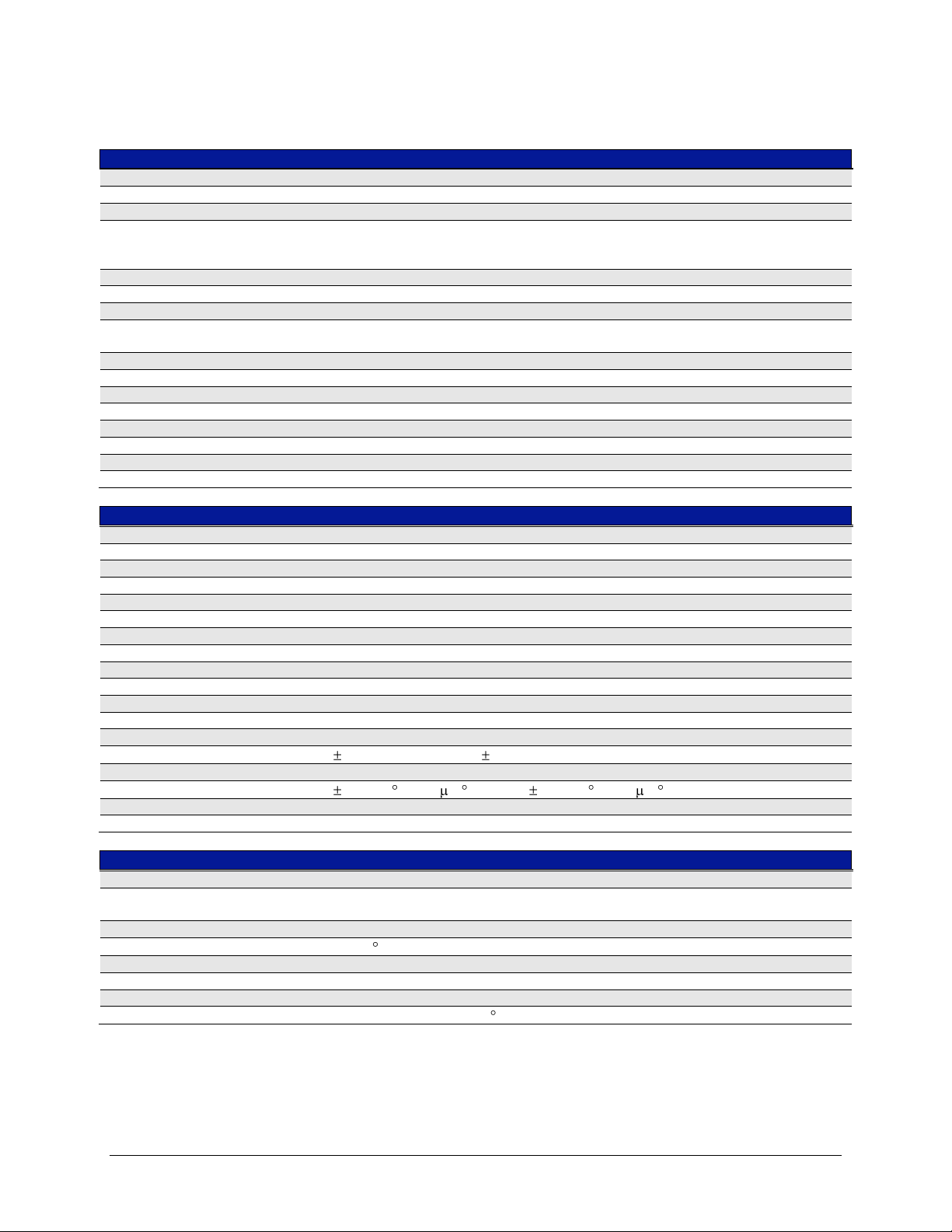
VTI Instruments Corp.
GENERAL SPECIFICATIONS
CHANNELS
48 differential inputs
FUNCTIONS (STRAIN)
Quarter 120 Ω, Quarter 350 Ω, Quarter User-Defined,
Half-Bending, Half-Poisson,
Full-Bending, Full-Poisson, Full-Bending Poisson
FUNCTIONS (NON-STRAIN)
Voltage, Ratiometric, Linear
SAMPLING RATE
For All Channels
For 16 Channels
30 settings from 1 Sa/s to 10000 Sa/s per channel
Up to 25000 Sa/s (see Explanation of Specifications for limitations.)
A/D CONVERSION
24-bit ΔΣ converter per channel
GAINS
1, 10, or 100, software selectable
NETWORK CONNECTION
10/100 Base-T Ethernet
INPUT CONNECTOR
RJ-45
BRIDGE EXCITATION
REGULATION
Independent high-side and low-side control on a per channel basis
HIGH-SIDE RANGE
0 to +8 V
LOW-SIDE RANGE
0 to -8 V
RESOLUTION
14-bit (500 µV)
SENSE
Local or remote
CURRENT OUTPUT
50 mA per channel, short circuit limited to 60 mA
SET POINT ACCURACY
(0.04% + 2 mV) typical, (0.07% + 10 mV) maximum, for │V
EXC
│> 20 mV
STABILITY
(20 ppm/ C + 20 V/ C) typical, (30 ppm/ C + 60 V/ C) maximum
RESPONSE TIME
Suddenly changed load
< 20 µs to stabilize within 1% of setting
BRIDGE COMPLETION
RESISTOR VALUE
120 Ω, 350 Ω, and user-specified, software selectable
User value available as factory option.
RESISTOR STABILITY
5 ppm/ C
INPUT CONNECTOR LEAD RESISTANCE
30 mΩ minimum, 60 mΩ maximum, matched to <5 mΩ within each channel
BACK-HALF RESISTORS
10 kΩ/10 kΩ, 0.1%, 2 ppm/ C
EX1629 SPECIFICATIONS
18 EX1629 Introduction
Page 19

www.vtiinstruments.com
SHUNT CALIBRATION
INTERNAL RESISTOR
55 kΩ (0.1%, 25 ppm/°C) per channel standard (0.05%, 5 ppm/°C optional)
EXTERNAL RESISTOR
Front panel connection shared among 16 channels
Connection resistance: 16 Ω typical
RESISTOR CONNECTION
Software selectable: local (across completion resistor) or remote
QUARTER-BRIDGE STRAIN MEASUREMENTS
Excitation
Gain
Range
1
Gain Accy
2
Offset Accy
2,3
Gain TC
4
Offset TC
4
10 V
100
+30927 µε/-29126 µε
±0.12%
±25 µε
±50 ppm/ºC
±4 µε/ºC
5 V
100
+63829 µε/-56603 µε
±0.12%
±25 µε
±50 ppm/ºC
±4 µε/ºC
Note 1: Nominal for balanced bridge
Note 2: Conditions:
GF = 2.0, R
comp
= 350 Ω, balanced excitation
<30 days, ±5 ºC from last self-calibration
15 ºC to 35 ºC, 1 year from full calibration
Assumes the excitation voltage is measured and used in the conversion. Valid for 30 days, ±5 ºC.
Includes the stability effects of the excitation source.
60 minute warm-up
Exclusive of lead wire desensitization errors
Exclusive of gage errors
Exclusive of noise
Note 3: <30 days, ±5 ºC from unstrained voltage measurement.
Note 4: Only applies outside of self-calibration window
FULL-BRIDGE STRAIN MEASUREMENTS
Excitation
Gain
Range
1
Gain Accy
2
Offset Accy
2,3
Gain TC
4
Offset TC
4
5 V
100
±15000 µε
±0.05%
±1.5 µε
±50 ppm/ºC
±0.2 µε/ºC
2.5 V
100
±30000 µε
±0.06%
±3 µε
±60 ppm/ºC
±0.4 µε/ºC
Note 1: Nominal for balanced bridge
Note 2: Conditions:
GF = 2.0, balanced excitation, remote sense
<30 days, ±5 ºC from last self-calibration
15 ºC to 35 ºC, 1 year from full calibration
Assumes the excitation voltage is measured and used in the conversion. Valid for 30 days, ±5 ºC.
Includes the stability effects of the excitation source.
60 minute warm-up
Exclusive of gage errors
Exclusive of noise
Note 3: <30 days, ±5 ºC from unstrained voltage measurement.
Note 4: Only applies outside of self-calibration window
CONFIDENCE MEASUREMENTS
TOTAL EXCITATION VOLTAGE
±(0.012% + 500 µV)
±EXCITATION VOLTAGE
±(0.012% + 2.5 mV)
±EXCITATION CURRENT
±(0.1% + 50 µA)
COMMON MODE VOLTAGE
±(0.1% + 2.5 mV)
SAMPLING RATE
Approximately 500 Sa/s
EX1629 Introduction 19
Page 20
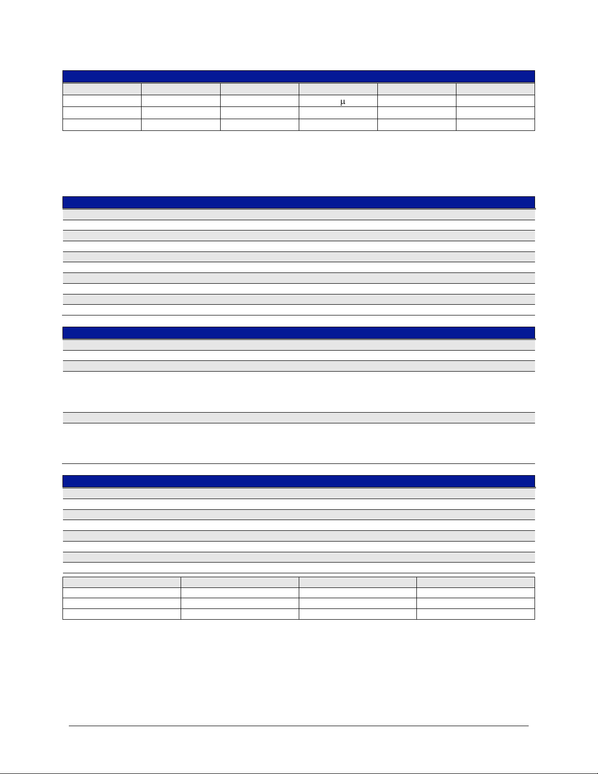
VTI Instruments Corp.
VOLTAGE MEASUREMENTS
Gain
Range
Gain Accy
1
Offset Accy
1
Gain TC
2
Offset TC
2
100
±150 mV
±0.025%
±15 V
±30 ppm/ºC
±2 µV/ºC
10
±1.5 V
±0.025%
±100 µV
±30 ppm/ºC
±12.5 µV/ºC
1
±15 V
±0.025%
±700 µV
±30 ppm/ºC
±125 µV/ºC
Note 1: Conditions:
<30 days, ±5 ºC from last self-calibration
15 ºC to 35 ºC, 1 year from full calibration
60 minute warm-up
Exclusive of noise
Note 2: Only applies outside of self-calibration window.
INPUT CHARACTERISTICS
INPUT IMPEDANCE (dc)
10 GΩ
INPUT BIAS CURRENT
10 nA maximum
INPUT PROTECTION
±25 V
COMMON MODE INPUT RANGE
±15 V
CMRR (dc TO 60 Hz)
120 dB typical, 110 dB minimum (Gain = 100)
FILTERING
ANALOG ANTI-ALIAS LPF
60 kHz 1-pole per channel
DIGITAL FIR FILTERING
Passband ripple
fs ≥ 3125 Hz
fs < 3125 Hz
Alias rejection
Achieves desired sampling frequency by decimation from 50000 Sa/s.
±0.01 dB
±0.001 dB
100 dB
DIGITAL IIR FILTERING
Configuration options per channel
Type (Bessel, Butterworth, None)
Cut-off frequency (0.001 Hz to 4005 Hz)
Transform (Bilinear or Matched Z)
Order (1-10)
WIDEBAND OUTPUTS
CHANNELS
1 per input channel
CONNECTORS
(3) 44-pin male D-sub
MAXIMUM OUTPUT VOLTAGE
±15 V
OUTPUT IMPEDANCE
150 Ω
Gain
Gain Accy
Offset Accy (RTI)
Bandwidth (-3 dB)
100
±0.15%
±150 µV
> 100 kHz
10
±0.15%
±500 µV
> 150 kHz
1
±0.15%
±5 mV
> 150 kHz
20 EX1629 Introduction
Page 21

www.vtiinstruments.com
DIGITAL I/O
CHANNELS
16
CONNECTOR
(1) 44-pin female D-sub
ELECTRICAL
V
INPUT
-0.5 V to 5.5 V
VIH
2 V minimum
VIL
0.8 V maximum
V
OH (IOH
= -5.2 mA)
2.5 V minimum
VOL (IOL = 48 mA)
0.5 V maximum
TRIGGER BUS
CHANNELS
8
CONNECTORS
(2) Micro DB-25
ELECTRICAL
Logic type
M-LVDS Type 1
V
IT+
50 mV maximum
V
IT-
-50 mV minimum
VOS
1 V typical
POWER REQUIREMENTS
LINE VOLTAGE
90 – 250 V ac (50 / 60 Hz)
INPUT POWER
200 VA maximum
PLUG RATINGS
IEC
UL
10 A / 250 VAC; 50 Hz
15 A / 250 VAC; 50/60 Hz
ENVIRONMENTAL
OPERATING TEMPERATURE
-5 °C to +55 °C
HUMIDITY
5% to 85% relative humidity
MECHANICAL
HEIGHT
3.5 in (8.89 cm)
WIDTH
19 in (48.26 cm)
DEPTH
22 in (55.88 cm)
EX1629 Introduction 21
Page 22

VTI Instruments Corp.
EXPLANATION OF SPECIFICATIONS
This section provides explanatory notes to certain elements of the EX1629 specifications that may
be confusing or easily misunderstood.
Sampling Rate
The EX1629 ADCs run at 50 kSa/s and data is decimated down by an integer factor to the userselected sample rate. The EX1629 is capable of supporting a sampling rate of 10 kSa/s on all
48 channels simultaneously. Over a limited number of channels, however, the EX1629 is capable
of supporting a sample rate of 25 kSa/s. In order to realize this higher sampling rate, the number of
operating channels must be limited to 16 maximum and these channels must all exist on the same
analog board (i.e. channels 0 through 15, 16 through 31, or 32 through 47 can be selected). If these
conditions are not met, an error will occur.
Bridge Excitation
Performance of the excitation source is quantified in two ways. Set point accuracy refers to the
absolute accuracy of the excitation output compared to its nominal programmed value.
Conversely, stability refers to the drift characteristics of the source once it has been programmed
to a specific value. Since the EX1629 provides the ability to measure the excitation source and use
the measured value in the EU conversion, it is the source’s stability that ultimately effects strain
measurement accuracy, not its set point accuracy.
While the source’s performance characteristics are provided, they should not be added to the listed
quarter-bridge and full-bridge accuracy tables, as these accuracy tables already contain the effects
of the excitation source stability. The source characteristics are listed for reference and for the
possibility that a user might use the EX1629 to provide bridge excitation, but another piece of
equipment to measure the bridge output. In that case, the excitation performance is required in
order to calculate the total system uncertainty. For this analysis, it must be noted that the listed
characteristics are for each source independently.
Bridge Completion
The characteristic input connector lead resistance refers to the residual resistance that the input
connector represents in a quarter-bridge configuration. Specifically, referring to Figure 2-3, this is
the resistance between Pin 1 (+Excitation) of the connector and the local connection of the
+Excitation Sense line. Similarly, it is the resistance between Pin 2 (-Excitation) and the point at
which the completion resistor is shunted. These resistances serve to slightly desensitize a quarterbridge configuration, even in the absence of external lead wire resistances. This resistance is
specified from 30 mΩ to 60 mΩ, depending on the selected channel. This results in an
uncompensated gain error on a 350 Ω bridge of 86 ppm to 172 ppm.
This error is not reflected in the quarter-bridge accuracy table, however, because it is assumed that
lead wire compensation will be done to remove the effects of external lead wire resistance. That
process will simultaneously and completely compensate for this resistance, as it is matched within
each channel to within 5 mΩ. If the lead wire compensation is done via shunt calibration, the
30 mΩ possible difference between channels is unimportant, as each channel will undergo a
unique shunt calibration. If, however, the lead wire compensation is done theoretically (as one
might do if the connecting cable is well characterized), an average compensation of 129 ppm
should be used for the internal resistance. This would leave a possible uncompensated error of
only 43 ppm.
Automatic measurement is possible, conversely, using the traditional shunt calibration process.
Shunt calibration is the process of placing a known resistance in parallel with one of the bridge
elements to create a known simulated strain. For quarter-bridge configuration, this element is
usually the internal completion resistor. In this method, the deviation of the actual measured strain
22 EX1629 Introduction
Page 23
www.vtiinstruments.com
from the theoretical strain is then considered to be due to lead wire desensitization, and a
compensation factor is determined. However, some strain purists argue that shunt calibration is
actually meant to be a verification step and should not be used for this purpose. What is needed,
then, is an automated way to determine the lead wire desensitization error without using shunt
calibration. This can be accomplished using the vtex1629_set_lead_wire_resistance and
vtex1629_set_half_bridge_lead_wire_desensitization functions. An additional API is available to
help measure the lead wire resistance, beginning with firmware version 1.0:
vtex1629_measure_lead_wire_resistance.
NOTE This functionality was added to the EX1629 after September 2006 in firmware version 1.0. To
ensure compatibity, use the instrument’s embedded web page interface or use the EX1629’s
vtex1629_revision_query function.
Shunt Calibration
Shunt calibration can be performed with either the internal 55 kΩ resistor or an external resistor
inserted into the front panel shunt connector. For highest accuracy, the value of this external
resistor should be precisely known. The connection resistance characteristic refers to the series
resistance of the switch mechanisms used to route the external resistor into the requested bridge
circuit. This resistance must be considered in conjunction with the raw resistor value when
determining the theoretical simulated strain of the shunt calibration process. The connection
resistance is the same for local or remote connection.
Quarter-Bridge Strain Measurement
The strain dynamic range is slightly different for tension vs. compression. While the dynamic
range of the voltage measurement circuitry is a balanced ±160 mV, the transfer function of strainto-voltage is nonlinear for quarter-bridge configuration, and that results in the small disparity.
Quarter-bridge measurement accuracy is noted as being exclusive of lead wire desensitization
errors. This refers to the gain error that is generated by lead wire resistance in series with the
actual strain gage. Depending on the length and gauge of the wire employed, the resultant
resistance can cause errors that are much larger than the underlying instrument accuracy. Precision
measurements consequently demand that lead wire compensation is conducted to eliminate this
error. This compensation can be calculated theoretically if the resistance of the connection wire is
characterized or can be inferred through the shunt calibration process. Reference the Bridge
Completion paragraph above for information on how to compensate for the lead wire resistance
that is internal to the EX1629.
Quarter-Bridge Strain Measurement/Full-Bridge Strain Measurement
The key concepts regarding the conditions on the strain measurement accuracy tables are:
The stability effects of the excitation source are already captured in the listed accuracies. It is
thus not necessary to combine the two to create a total system accuracy. The listed strain
accuracies are already for the entire EX1629 measurement system.
The accuracies do assume that the excitation voltage is measured and used in the EU
conversion before the initiation of strain measurements. This eliminates its set point accuracy
from being an error source.
The restriction of 30 days, ±5 °C is used throughout the conditions. Essentially the intention is
to describe a strain test setup that is initiated with a self-calibration, excitation voltage
measurement, and unstrained voltage measurement. From that point, continuous strain
measurements are considered to be taken over ambient conditions of 30 days, ±5 ºC.
EX1629 Introduction 23
Page 24

VTI Instruments Corp.
The advantage to specifying in this way is that it provides maximum values that correspond to real
world conditions. For in a production environment, it is impractical to allow, for example, only a
±1 ºC temperature swing. Similarly, since many strain tests can be very long in duration, it is
impractical to demand a daily self-calibration or excitation voltage measurement.
The disadvantage, however, is that these assumptions result in measurement uncertainties that are
overstated for test sequences that are significantly shorter in duration and subject to less
environmental movement. However, since the gain and offset temperature coefficients are
provided, the resultant performance improvements can be interpolated.
Wideband Outputs
The offset accuracy of the wideband outputs is provided referred to input (RTI). This is the
accuracy of the calculated input signal. When considered in its raw form at the connector, namely
referred to output (RTO), the listed accuracies must be multiplied by the gain of the range used.
The bandwidth specifications for each range were generated for an output sine wave signal of 2 V
peak-to-peak. Very large signals (as a percentage of range) will encounter slew rate limiting and
have a lower effective bandwidth.
Confidence Measurements
There are two specifications listed for excitation voltage measurement. The ±excitation voltage
accuracy refers to the uncertainty of each excitation source measurement as an independent
measurement. Conversely, the total excitation voltage accuracy refers to the uncertainty of the
combined excitation source measurement, specifically the difference between the +excitation
voltage and the –excitation voltage. This quantity has a lower uncertainty, because, as a difference
measurement, it is subject to fewer error sources. While these performance characteristics are
provided, they should not be added to the listed quarter-bridge and full-bridge accuracy tables, as
these accuracy tables already contain the effects of the excitation voltage measurement.
The excitation current measurements are defined such that current flowing out of the source is
positive current and current flowing into the source is negative current. Consequently, the
+excitation current quantity is nominally a positive number, and the –excitation current quantity
is nominally a negative number. Moreover, the current measurements are defined to be the total
current of the source, not just that flowing in the external bridge. As shown in Figure 2-3, there is
a 20 kΩ resistance, represented by the back-half resistors, that is always connected between the
excitation sources. As a result, nonzero excitation source values will generate nonzero excitation
currents even if the input channel is open. For example, a total excitation voltage of 5 V on an
unpopulated channel will nominally display excitation currents of ±250 µA.
MAXIMIZING MEASUREMENT PERFORMANCE
This section discusses tips and procedures that can help maximize the actual performance realized
with the EX1629 and aid the user in avoiding some common pitfalls associated with strain gage
measurement.
Utilize self-calibration
Self-Calibration should be conducted as often as practical, especially if the ambient environment
has changed significantly since the previous calibration. However, fast ambient environmental
changes should ideally be followed by a period of thermal stabilization before conducting selfcalibration. The self-calibration process completes quickly and does not require removal of the
actual input connections, making it convenient to run often.
24 EX1629 Introduction
Page 25

www.vtiinstruments.com
leadgage
lead
RR
R
error
Utilize excitation measurement
Measurement accuracy is notably improved by utilizing the EX1629’s ability to measure its
excitation source and use the measurement in the EU conversion. By doing so, the set point
accuracy of the excitation source ceases to be an error source. The strain accuracy tables are based
on the assumption that excitation measurement is performed.
While a tightly regulated supply, the excitation source does, nonetheless, have a temperature drift
characteristic. For this reason, it is best to conduct the excitation source measurement just prior to
the initiation of strain measurements, making the source measurement as current as possible.
Utilize proper strain gage wiring techniques
In addition to the accuracy of the measuring instrument, the total system accuracy of the strain
measurement is a function of the gage characteristics and the connection wiring of the gage to the
measuring instrument. Nonideal wiring techniques can create measurement inaccuracies far above
those of the measuring instrument.
For half- and full-bridge configurations, it is highly recommended that the remote excitation sense
lines be used on the excitation source, as shown in Figure 2-4 and Figure 2-5, respectively. These
lines should be connected at the same point that the ±Excitation lines are connected to the bridge.
Ultimately, the excitation source regulates based on the voltage present on its sense lines. Without
remote sense, this regulation point is at the EX1629 input connector. This is a nonideal connection
because the lead wire resistance between the EX1629 and the bridge will create a voltage drop,
lowering the effective excitation value at the bridge. Remote sense inherently compensates for the
lead wire resistance and delivers the correct excitation value.
For quarter-bridge configurations, it is highly recommended that the full 3-wire connection be
used, as shown in Figure 2-3. Specifically, it is important that the –Sense line be connected at the
gage, instead of locally at the EX1629 input connector. The 3-wire connection reduces the total
lead wire resistance seen by the gage by putting half of it in series with the completion resistor.
Not only does this reduce the static lead wire desensitization error, but it also provides an inherent
level of temperature compensation. Specifically, since the same lead wire resistance is in the
active leg as well as the completion leg, any variation of the resistance due to temperature
naturally occurs in both legs and cancels.
Compensate for lead wire desensitization error
Even if the 3-wire connection is employed in quarter-bridge configuration, there may still be
significant error in the measurement, as there is lead wire resistance that does not move with the
underlying strain, but is indistinguishable from the actual gage resistance. This results in the
measured strain being systematically in error. Depending on the length and gauge of the wire
employed, this error may be much larger than the underlying instrument accuracy. Precision
measurements consequently demand that lead wire compensation is conducted to eliminate this
error. The error arises from the fact that the measuring instrument cannot distinguish between the
resistance of the lead wires and the resistance of the strain gage. Specifically, when the resistance
of the gage changes under load, the measuring instrument reads a strain value lower than the true
value, because part of the total resistance it considers to be the gage is not changing. The extent of
the desensitization error is dependent on the resistance values of the gage and the lead wire,
related by this equation:
EX1629 Introduction 25
Page 26

VTI Instruments Corp.
02849.0
1350
1
error
For example, lead wire resistance of 1 Ω on a 350 Ω gage causes a desensitization error of:
Because it is a gain error, it is easily compensated if the desensitization can be measured or
calculated prior to the commencement of the strain testing. Depending on the abilities of the data
collection mechanism, the compensation can be done as a post-acquisition mathematical
operation, through manipulation of the gage factor in the calculation equation, or through internal
gain compensation based on an inputted lead wire value.
But, regardless of how the compensation is conducted, the first step in the process is to determine
the value of the desensitization for each measurement channel in the system. Depending on the
consistency of the test setup and the accuracy desired, there are two common ways of determining
the error. The most basic way is simply to measure the resistance value of the lead wire with a
DMM during the gage installation process. However, for a large channel count application with
little consistency in the distance between the sensors and the measuring instrument, this would
require the manual measurement and tracking of hundreds of wires, an obviously arduous task.
This compensation can be calculated theoretically if the resistance of the connection wire is
characterized or can be inferred through the shunt calibration process, or by calling the
vtex1629_set_lead_wire_resistance and vtex1629_set_half_bridge_lead_wire_desensitization
functions. Please reference the Bridge Completion subsection in Section 1 for information on how
to compensate for the lead wire resistance that is internal to the EX1629.
Allow for thermal stabilization of the bridge
Compared to other sensor measurements, bridge measurements inherently involve relatively high
amounts of power dissipation. Power is dissipated in the excitation source, the completion resistor,
as well as the gage itself. The power dissipation is not so much a problem as a change in power.
Specifically, when the excitation source value is changed, the amount of power being dissipated in
the various bridge elements changes. A power dissipation change then leads to a temperature
change through the thermal impedance of each element. Temperature change then ultimately
results in performance characteristic drift. Since bridge power is directly related to the excitation
current amount, this issue is worsened by increasing the excitation voltage or decreasing the
bridge resistance.
To achieve maximum performance, it is best to allow the system elements to thermally stabilize
once the bridge configuration has been programmed and the excitation source set and enabled.
This time will be largely driven by the characteristics of the strain gage chosen for the application,
and should be determined empirically. Only after this time should the excitation and unstrained
voltage measurements be conducted.
26 EX1629 Introduction
Page 27
www.vtiinstruments.com
SECTION 2
PREPARATION FOR USE
OVERVIEW
This section provides a step-by-step process for setting up the EX1629 for use. It covers hardware
installation, input connections, and software installation.
UNPACKING/INSPECTION
When the EX1629 is unpacked from its shipping carton, the contents should include the following
items:
EX1629 High-Performance Strain Gage Instrument
Power line cord
EX1629 User’s Manual (this manual)
VTI Instruments Corp. Drivers and Product Manuals CD
All components should be immediately inspected for damage upon receipt of the unit. If any
visual damage is observed or if the unit behaves in an unexpected manner after initial start up,
please contact VTI Instruments to return the unit for repair.
INSTALLATION LOCATION
The EX1629 is designed to be largely insensitive to external electrical, magnetic, and thermal
disturbances. However, as with all precision instrumentation, certain precautions, if taken into
consideration, can help achieve maximum performance.
1) The unit, particularly its front panel, should be located away from sources of extreme high or
low temperatures.
2) The unit should be located away from sources of high magnetic fields such as motors,
generators, and power transformers.
The EX1629 employs active cooling for maximum product reliability. Fans located at the rear of
the instrument pull ambient air through holes on the sides of the chassis and exhaust it out through
the rear. The unit’s installation with regards to other instrumentation and mounting cabinetry
should ensure that the intake holes and exhaust fans remain unobstructed.
NOTE When selecting the installation location, be certain that there is enough space around the power
plug and the outlet so that they are readily accessible. Do not insert the power plug into an outlet
where accessibility to the plug and outlet is poor.
EX1629 Preparation for Use 27
Page 28

VTI Instruments Corp.
CONNECTING/DISCONNECTING LINE POWER
When connecting the EX1629 to an outlet, there should be no connections to the front panel and
the power switch at the rear of the mainframe should be in the off position. Connect the power line
cord provided to the EX1629 and the outlet, then turn the power switch to the on position.
To power down the EX1629, disconnect all connections to the front panel, move the power switch
at the to the off position, then disconnect the power line cord from the outlet.
WARM-UP TIME
The specified warm-up time of the EX1629 is 60 minutes. If, however, the unit is being subjected
to an ambient temperature change greater than 10 C, extra stabilization time is recommended to
achieve maximum performance.
SOFTWARE INSTALLATION
The fastest way to begin controlling an EX1629 is to discover the unit using VTI’s LAN
Instrument Connection and Upgrade (or LInC-U) utility. To do this, the following is required:
A PC or laptop computer
A Microsoft™ Windows™ XP OS with Service Pack 2 (SP2) and Internet Explorer™ (IE)
An Internet connection
VTI’s LInC-U utility
The LInC-U Utility searches for all LAN-based VTI devices on the network and can be found on
the Distribution CD that shipped with the EX1629 or may be downloaded from the
VTI Instruments corporate website. This utility uses the VXI-11 discovery protocol to discover the
EX1629. This utility can also be used to upgrade the EX1629’s driver and firmware. For more
information on using the LInC-U utility, please refer to its online Help file. For more information
on discovering the EX1629, please refer to Opening the Web Page in Section 5.
LInC-U Installation
To install LInC-U as a discovery tool for the EX1200’s embedded webpage, insert the
VTI Instruments Corp. Drivers and Product Manuals CD into the host PCs CD-ROM and, using
Windows Explorer, navigate to the <CD-ROM Drive>:\EX Platforms Requisites directory. Next,
run the VTI_LInC-U_setup.exe program. Once installation begins, simply follow the on-screen
instructions.
INPUT CONNECTIONS / WIRING
Extensive testing has resulted in the qualification of the standard RJ-45 telecom connector as the
ideal low-cost connector for strain gages. Not only are these connectors reliable, but low-cost
construction of custom length cables is also readily available. Reconfiguration or replacement of
strain gage connections is as easy as connecting a telephone. An example cable connection is
illustrated in Figure 2-1.
Figure 2-2 shows the pin assignment for each EX1629 strain gage connector. Depending on the
bridge configuration employed, anywhere from three to all eight of the signal connections will be
actively used, as illustrated in the bridge configuration diagrams that follow. For proper operation,
unused input connections must be left open, as opposed to being grounded or tied together.
28 EX1629 Preparation for Use
Page 29
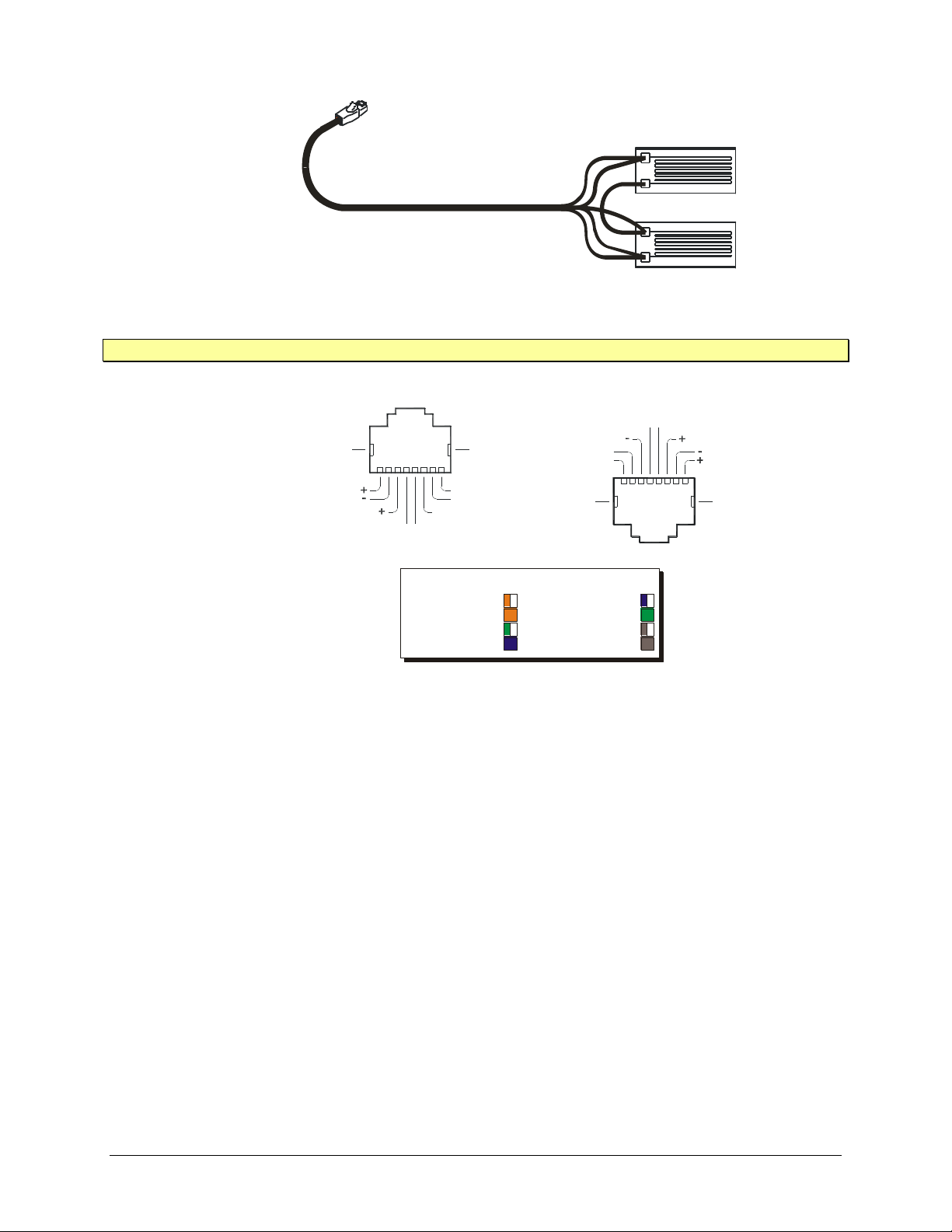
RJ-45 Modular Connector (Shielded)
8-Conductor Twisted-Pair, Overall-Shielded
(Example Half-Bridge Connection)
FIGURE 2-1: CONNECTING STRAIN GAGES
Color Coding per TIA/EIA-568-B
Pin 1 - Orange/White
Pin 2 - Orange
Pin 3 - Green/White
Pin 4 - Blue
Pin 5 - Blue/White
Pin 6 - Green
Pin 7 - Brown/White
Pin 8 - Brown
Pinout for Upper Connector Row
Excitation Sense
Shield Gnd
Sense
Excitation
R Cal
Sense
-
+
-
-
+
Shield Gnd
65421
3
8
7
Shield Gnd
Excitation Excitation Sense
R Cal
+
-
-
+
Shield Gnd
321 4 5 6 7 8
SenseSense
Pinout for Lower Connector Row
NOTE Unused user connections must be left open.
www.vtiinstruments.com
BRIDGE CONFIGURATIONS
EX1629 Preparation for Use 29
Depending on the bridge configuration and cable length employed, the wire gauge (and thus
resistance) of the input connections can be a factor in determining ultimate system performance.
For example, in a full-bridge configuration using excitation remote sense, the measurements are
insensitive to the resistance of all connections. However, in a quarter-bridge configuration, the
resistance of the +Excitation and –Excitation connections can be a significant error source if not
properly compensated. For more details, see Maximizing Measurement Performance in Section 1.
Figure 2-3 illustrates how to connect a single strain gage in quarter-bridge configuration. As
explained in Maximizing Measurement Performance in Section 1, the –Sense line should ideally
be connected at the gage, instead of locally at the EX1629 input connector. Moreover, the wire
length and gauge of the connections to Pins 1 and 2 should be matched. Fortunately, this is
typically guaranteed by routing both lines as part of the same cable. For this configuration, the
±Excitation Sense lines are not used and must be left open, as opposed to being grounded or tied
together. Whether the gage will be in tension or compression, the connection is the same.
FIGURE 2-2: INPUT CONNECTOR PIN ASSIGNMENT
Page 30
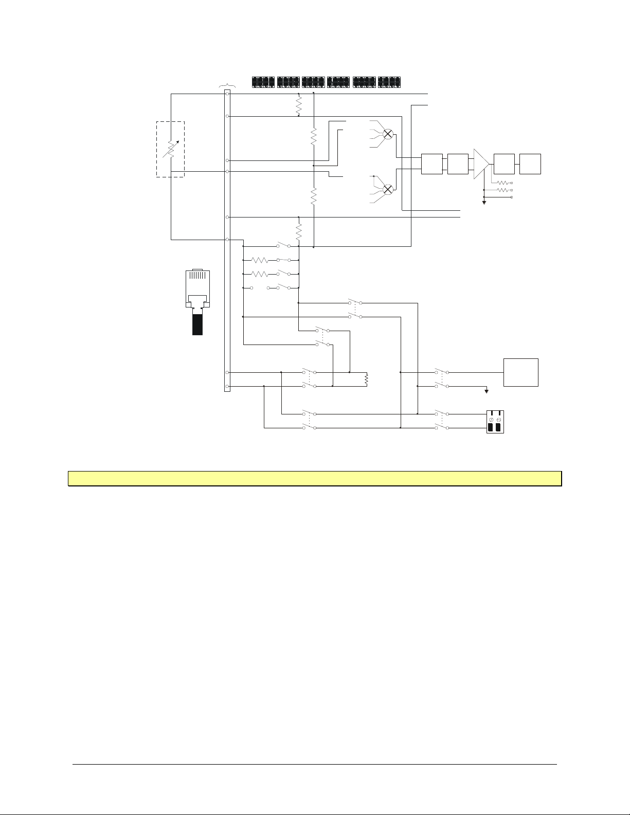
VTI Instruments Corp.
TEDS
COMM
External customer
shunt cal
resistor terminals
Internal
Rcal
55K
-R Cal
+R Cal
Pin 5
Pin 4
Strain
Bridge
8-pin telcom
connector (RJ-45)
350
120
User
10K
10K
+ Excitation
- Excitation
Quarter-Bridge
(1 of 48 channels)
+Excitation
+Sense
-Sense
+Excitation Sense
-Excitation Sense
-Excitation
+Excitation Sense
-Excitation Sense
RJ-45 Pin#
12345678
Pin 2
Pin 7
Pin 6
Pin 3
Pin 8
Pin 1
10K
10K
Instrumentation
Amplifier
+
-
x1
x10
x100
Hi
Lo
Shield
150
150
-Sense
-Cal
AGND
+Sense
Wagner
+Cal
AGND
430 kHz
LOW-PASS
FILTER
60.3 kHz
LOW-PASS
FILTER
ADC
TRIFILAR
FILTER
NOTE The ±Excitation Sense lines must be left open.
FIGURE 2-3: QUARTER-BRIDGE CONFIGURATION
30 EX1629 Preparation for Use
Page 31
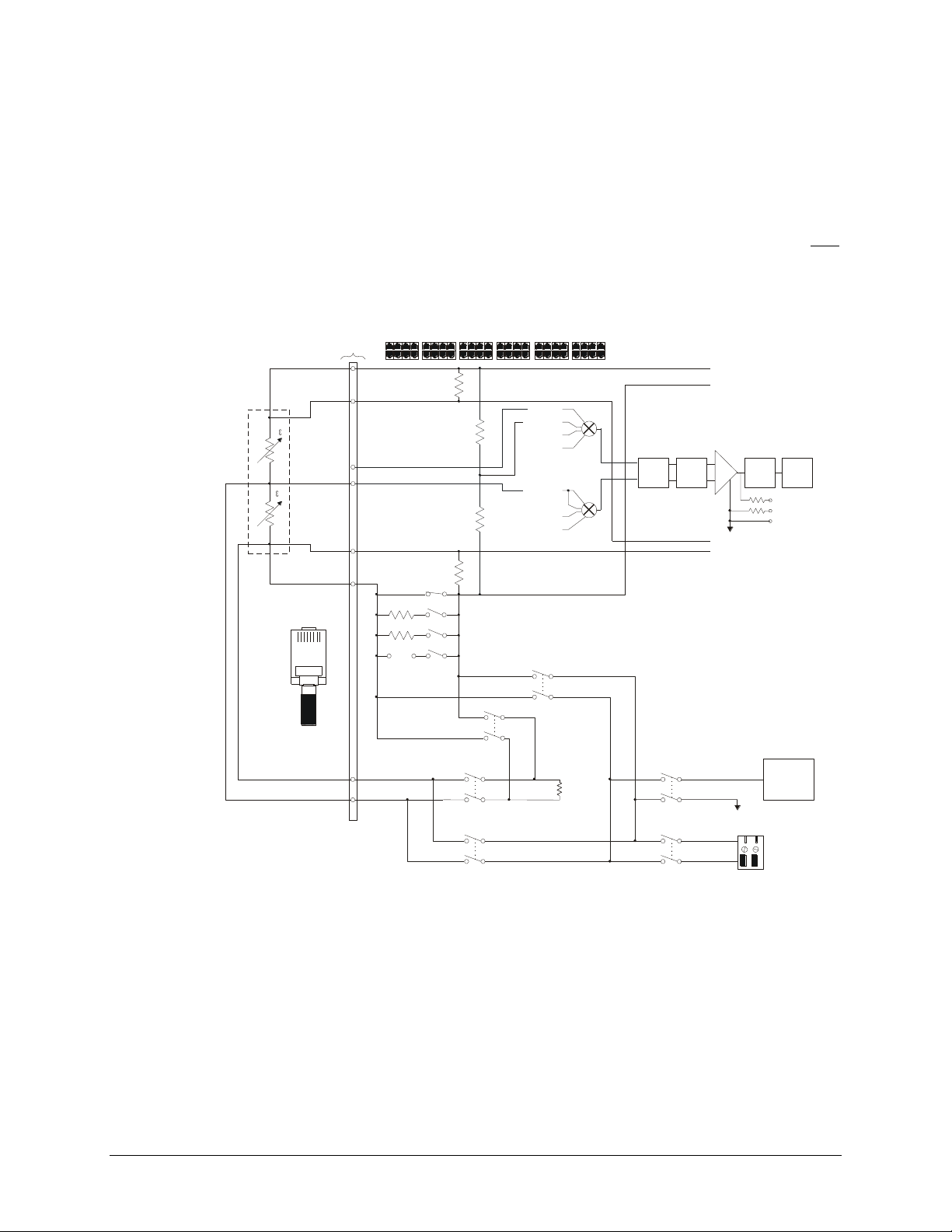
www.vtiinstruments.com
Strain
Bridge
8-pin telcom
connector (RJ-45)
350
120
User
10K
10K
+Excitation Sense
TEDS
COMM
External customer
shunt cal
resistor terminals
Internal
Rcal
55K
+ Excitation
- Excitation
Half-Bridge (1 of 48 channels)
+Excitation
+Sense
-Sense
-R Cal
+R Cal
+Excitation Sense
-Excitation Sense
-Excitation
-Excitation Sense
RJ-45 Pin#
12345678
Pin 5
Pin 4
Pin 2
Pin 7
Pin 6
Pin 3
Pin 8
Pin 1
+
-
10K
10K
Instrumentation
Amplifier
+
-
x1
x10
x100
Hi
Lo
Shield
150
150
-Sense
-Cal
AGND
+Sense
Wagner
+Cal
AGND
430 kHz
LOW-PASS
FILTER
60.3 kHz
LOW-PASS
FILTER
ADC
TRIFILAR
FILTER
Figure 2-4 illustrates how to connect two strain gages in basic half-bridge bending configuration.
As explained in Maximizing Measurement Performance in Section 1, the remote excitation sense
lines should ideally be used on the excitation source, connected at the same point that the
±Excitation lines are connected to the bridge. The shunt calibration lines (Pins 4 and 5), however,
are only necessary if that functionality is required. Note that the gage in tension is connected from
Pin 1 to Pin 3 and the gage in compression is connected from Pin 2 to Pin 3.
Furthermore, it is critical to understand how the EX1629 defines its measurement in this
configuration. Specifically, it defines the measured strain to be the strain that is present in each
gage, not the total of the two gages. For example, if the upper gage is subjected to tensile strain of
1000 µε and the lower gage is subjected to compressive strain of 1000 µε, the EX1629 will
measure a value of +1000 µε, not +2000 µε.
FIGURE 2-4: HALF-BRIDGE CONFIGURATION
Figure 2-5 illustrates how to connect four strain gages in basic full-bridge bending configuration.
As explained in Maximizing Measurement Performance in Section 1, the remote excitation sense
lines should ideally be used on the excitation source, connected at the same point that the
±Excitation lines are connected to the bridge. The shunt calibration lines (Pins 4 and 5), however,
are only necessary if that functionality is required. Note that the gages in tension are connected
from Pin 1 to Pin 6 and from Pin 2 to Pin 3 and the gages in compression are connected from Pin 2
to Pin 6 and from Pin 1 to Pin 3.
EX1629 Preparation for Use 31
Page 32
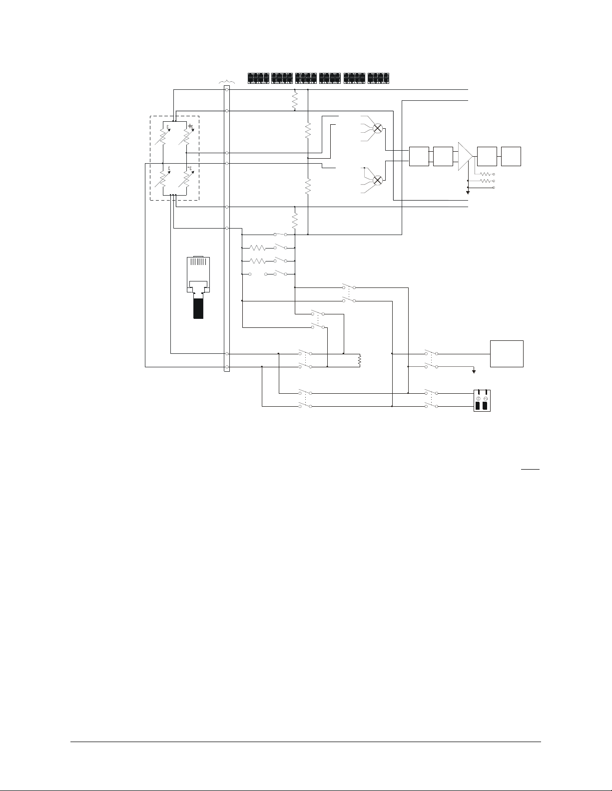
VTI Instruments Corp.
TEDS
COMM
External customer
shunt cal
resistor terminals
Internal
Rcal
55K
-R Cal
+R Cal
Pin 5
Pin 4
Strain
Bridge
8-pin telcom
connector (RJ-45)
350
120
User
10K
10K
+Excitation Sense
+ Excitation
- Excitation
Full-Bridge (1 of 48 channels)
+Excitation
+Sense
-Sense
+Excitation Sense
-Excitation Sense
-Excitation
-Excitation Sense
RJ-45 Pin#
12345678
Pin 2
Pin 7
Pin 6
Pin 3
Pin 8
Pin 1
+
-
-
+
10K
10K
Instrumentation
Amplifier
+
-
x1
x10
x100
Hi
Lo
Shield
150
150
-Sense
-Cal
AGND
+Sense
Wagner
+Cal
AGND
430 kHz
LOW-PASS
FILTER
60.3 kHz
LOW-PASS
FILTER
ADC
TRIFILAR
FILTER
FIGURE 2-5: FULL-BRIDGE CONFIGURATION
Furthermore, it is critical to understand how the EX1629 defines its measurement in this
VOLTAGE MEASUREMENT CONFIGURATIONS
configuration. Specifically, it defines the measured strain to be the strain that is present in each
gage, not the total of the four gages. For example, if the positive gages are subjected to tensile
strain of 1000 µε and the negative gages are subjected to compressive strain of 1000 µε, the
EX1629 will measure a value of +1000 µε, not +4000 µε.
The EX1629 main input channels can also be used for general voltage measurement. For this
application, the channel is effectively configured for Full-Bridge measurements (i.e., no
completion resistor or “back-half” of the bridge is enabled). The signal to be measured should be
connected to the +Sense and –Sense lines. The excitation source may be used in this mode, if the
measurement requires it, but the excitation source limits should be kept in mind.
For fully differential inputs, the configuration in Figure 2-6 should be used. For situations that
require a single-ended connection (i.e. one side grounded), the configuration in Figure 2-7 should
be used. When using these configurations, Negative Excitation Sense should be set to 0 V.
32 EX1629 Preparation for Use
Page 33
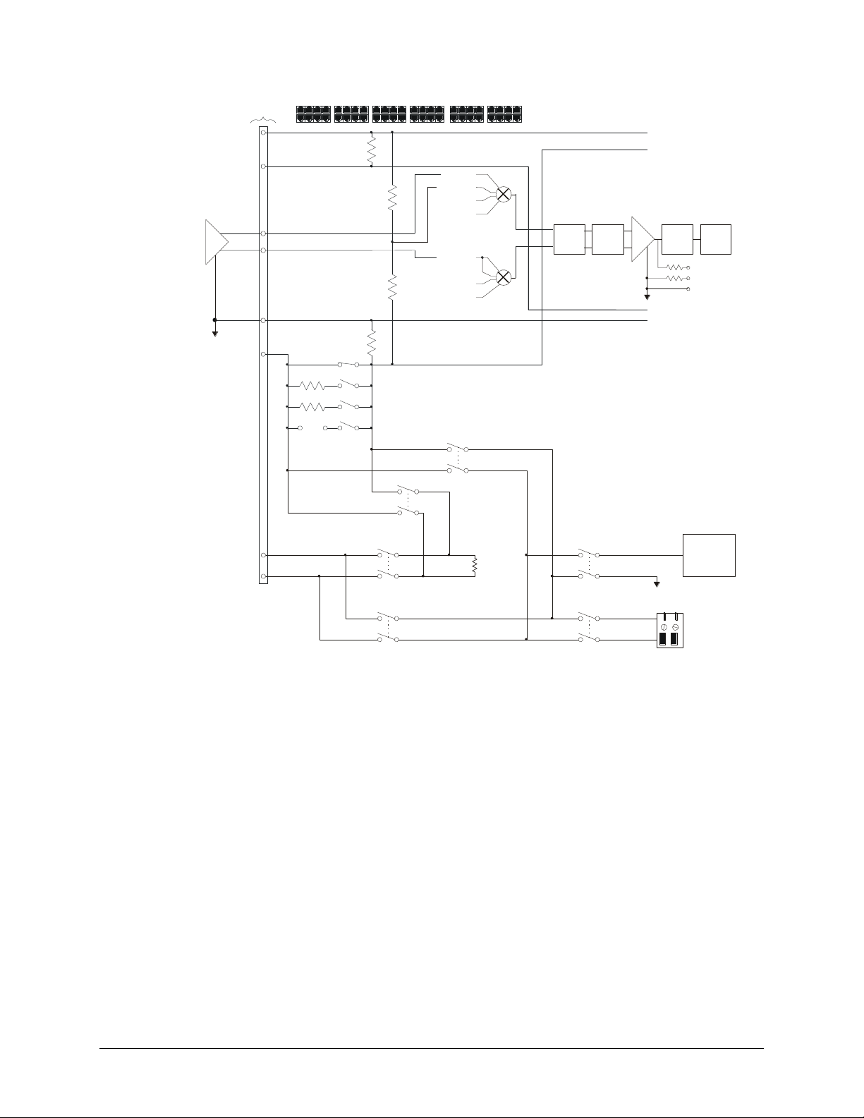
www.vtiinstruments.com
Voltage Measurement(1 of 48 channels)
TEDS
COMM
External customer
shunt cal
resistor terminals
Internal
Rcal
55K
-R Cal
+R Cal
8-pin telcom
connector (RJ-45)
350
120
User
10K
10K
+Excitation Sense
+ Excitation
- Excitation
+Excitation
+Sense
-Sense
+Excitation Sense
-Excitation Sense = 0 V
-Excitation
-Excitation Sense
10K
10K
Instrumentation
Amplifier
+
-
x1
x10
x100
Hi
Lo
Shield
150
150
-Sense
-Cal
AGND
+Sense
Wagner
+Cal
AGND
430 kHz
LOW-PASS
FILTER
60.3 kHz
LOW-PASS
FILTER
ADC
TRIFILAR
FILTER
HI
LO
* The parameter of the must be set to 0 V.negativeExcitationVoltage vtex1629_set_excitation function
FIGURE 2-6: VOLTAGE MEASUREMENT CONFIGURATION (DIFFERENTIAL INPUT)
EX1629 Preparation for Use 33
Page 34
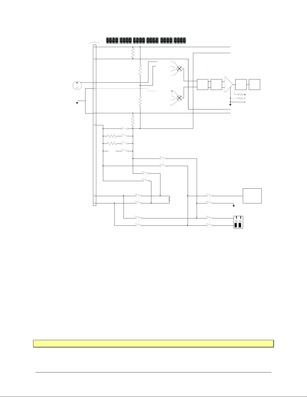
VTI Instruments Corp.
Voltage Measurement(1 of 48 channels)
TEDS
COMM
External customer
shunt cal
resistor terminals
Internal
Rcal
55K
-R Cal
+R Cal
8-pin telcom
connector (RJ-45)
350
120
User
10K
10K
+Excitation Sense
+ Excitation
- Excitation
+Excitation
+Sense
-Sense
+Excitation Sense
-Excitation Sense
* The parameter of the must be set to 0 V.negativeExcitationVoltage vtex1629_set_excitation function
-Excitation
-Excitation Sense
*
10K
10K
Instrumentation
Amplifier
+
-
x1
x10
x100
Hi
Lo
Shield
150
150
-Sense
-Cal
AGND
+Sense
Wagner
+Cal
AGND
430 kHz
LOW-PASS
FILTER
60.3 kHz
LOW-PASS
FILTER
ADC
TRIFILAR
FILTER
-Excitation Sense = 0 V
WIDEBAND OUTPUT CONFIGURATION
FIGURE 2-7: VOLTAGE MEASUREMENT CONFIGURATION (GROUNDED INPUT)
The wideband output connector, defined in Table 3-5, is a high-performance analog wideband
buffered output that can be connected to a high-speed digitizer for measuring structural vibration
levels. The Hi, Lo, and Shield pins of this connector are indicated in the shaded section of
Figure 2-8.
If a digitizer with a differential input will be connected to the wideband output, the Hi signal of
the digitizer should be connected to the Hi signal of the wideband output and the Lo signal of the
digitizer should be connected to the Lo signal of the EX1629.
If a digitizer with a single-ended input will be connected to the wideband output, the Hi signal of
the digitizer should be connected to the Hi signal of the wideband output and the ground of the
digitizer should be connected to the Shield pin of the wideband output connector.
NOTE The low-side of a single-ended digitizer should be isolated from chassis/earth ground.
34 EX1629 Preparation for Use
Page 35
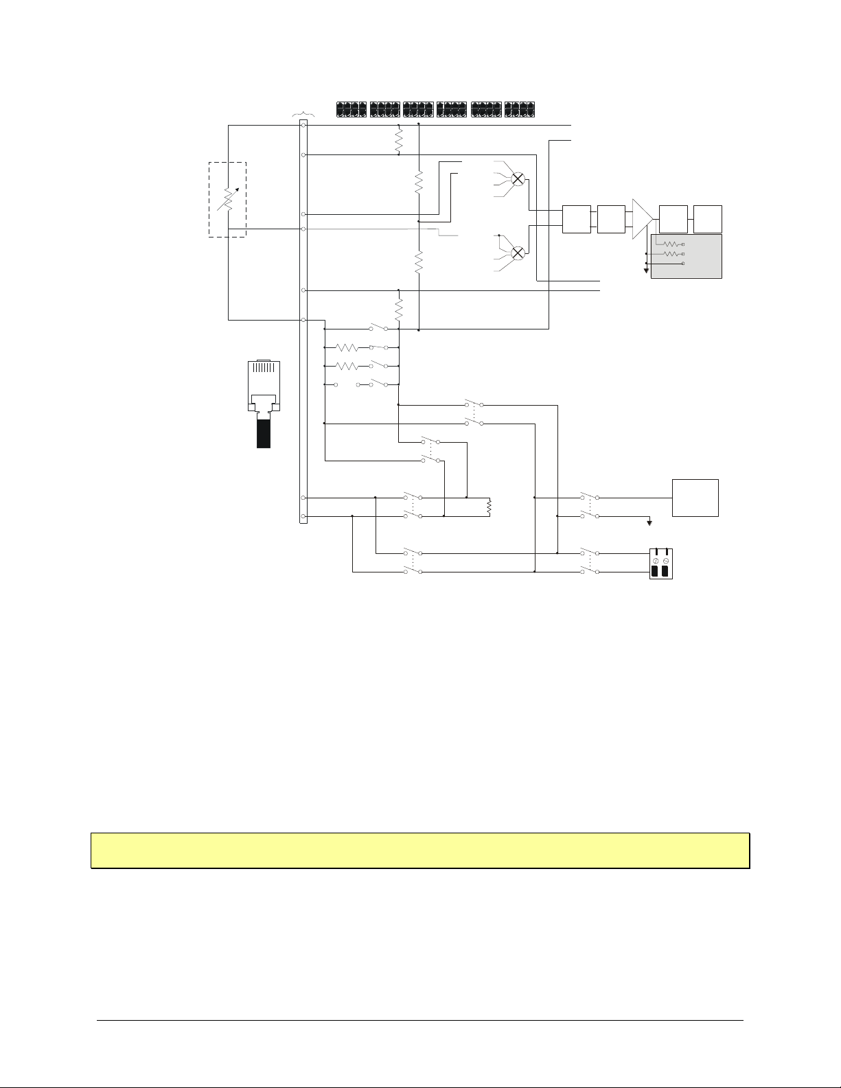
www.vtiinstruments.com
Wideband Output
TEDS
COMM
External customer
shunt cal
resistor terminals
Internal
Rcal
55K
-R Cal
+R Cal
Pin 5
Pin 4
Strain
Bridge
8-pin telcom
connector (RJ-45)
350
120
User
10K
10K
+ Excitation
- Excitation
(1 of 48 channels)
+Excitation
+Sense
-Sense
+Excitation Sense
-Excitation Sense
-Excitation
+Excitation Sense
-Excitation Sense
RJ-45 Pin#
12345678
Pin 2
Pin 7
Pin 6
Pin 3
Pin 8
Pin 1
Wideband Output
10K
10K
Instrumentation
Amplifier
+
-
x1
x10
x100
Hi
Lo
Shield
150
150
-Sense
-Cal
AGND
+Sense
Wagner
+Cal
AGND
430 kHz
LOW-PASS
FILTER
60.3 kHz
LOW-PASS
FILTER
ADC
TRIFILAR
FILTER
FIGURE 2-8: WIDEBAND OUTPUT DIAGRAM
DRIVER INSTALLATION
The EX1629 is shipped with a VTI Instruments Corp. Drivers and Product Manuals CD which
includes software drivers, user’s manuals, the VTI Instruments Product Catalog, as well as some
third-party software. Please refer to the ReadMe.txt file included on the Distribution CD for
installation instructions specific to revision of the CD provided.
NETWORK CONFIGURATION
With its default network configuration, the EX1629 will attempt to locate a DHCP server. If one is
NOTE At any time, the EX1629 can be returned to a known, default network configuration by using the
found, the IP address assigned by the DHCP server will be used. Otherwise, after a timeout of 20
seconds, the unit will attempt to obtain an IP address by using AutoIP.
LCI (LAN Configuration Initialize) mechanism. See Reset Button for more information.
EX1629 Preparation for Use 35
Page 36
VTI Instruments Corp.
MAC Address
AutoIP Default Address
00:0D:3F:01:00:01
169.254.1.1
00:0D:3F:01:01:01
169.254.1.1
00:0D:3F:01:A3:28
169.254.163.40
00:0D:3F:01:FE:FE
169.254.254.254
00:0D:3F:01:FF:FE
169.254.254.254
AutoIP is a mechanism for finding an unused IP address in the range 169.254.X.Y, where X is in
the range 1 - 254 and Y is in the range 0 - 255. The device will first attempt to obtain the specific
address 169.254.X.Y, where X and Y are the second-to-last and last octets (bytes) of the device’s
MAC address. However, X will be set to 1 if it is 0 in the MAC address, and to 254 if it is 255 in
the MAC address. This is in accordance with the AutoIP standard (RFC 3927). If this address is
already in use, the unit will attempt to obtain other IP addresses in a pseudorandom fashion until it
finds one that is available.
To illustrate the AutoIP mechanism, Table 2-1 lists the AutoIP default address for some example
MAC addresses.
If a static IP address assignment is preferred, one can be optionally assigned via the embedded
web page interface. This is done by clicking the Network Configuration link, disabling DHCP
and AutoIP, enabling Static, and then assigning a static IP address, subnet mask, and gateway
address, and, optionally up to three DNS servers (see Figure 5-3). For more information, see
Network Configuration in Section 5.
TABLE 2-1: AUTOIP DEFAULT ADDRESS ASSIGNMENT
NETWORK TROUBLESHOOTING
If an error occurs when trying to discover the EX1629 (see Web Page Operation in Section 5 for
more information on discovery), it may be necessary to change the network settings for the
EX1629 and the host PC. By using the following methodology, most network-related issues can
be resolved:
1) Restore the EX1629’s Default Network Settings
2) Determine PCs Network Settings
3) Set the EX1629 to Auto IP or Set the EX1629 to Static IP
4) Restore the Host PCs Network Settings
5) Using Multiple Network Cards
Restore the EX1629’s Default Network Settings
It may be the case that the EX1629 is in an unknown network configuration. The EX1629 can be
returned to its default state by pressing the Reset Button located at the rear of the chassis.
1) Power off the EX1629.
2) Press and hold the reset button.
3) Power on the EX1629.
4) Continue to hold the reset button for at least 30 seconds.
5) Release the reset button.
Determine PCs Network Settings
1) Ensure that all host PC Ethernet connections are made that will be used while controlling the
EX1629. If the PC will be connected to a LAN, ensure that the LAN connection is made.
2) From Windows , navigate to Start→Settings→Network Connections.
3) Right click on the connection that will be used to communicate with the EX1629, then select
Properties (see Figure 2-9). Some PCs have multiple network connections, so it is important
to make certain that the connection used to communicate with the EX1629 is selected.
36 EX1629 Preparation for Use
Page 37
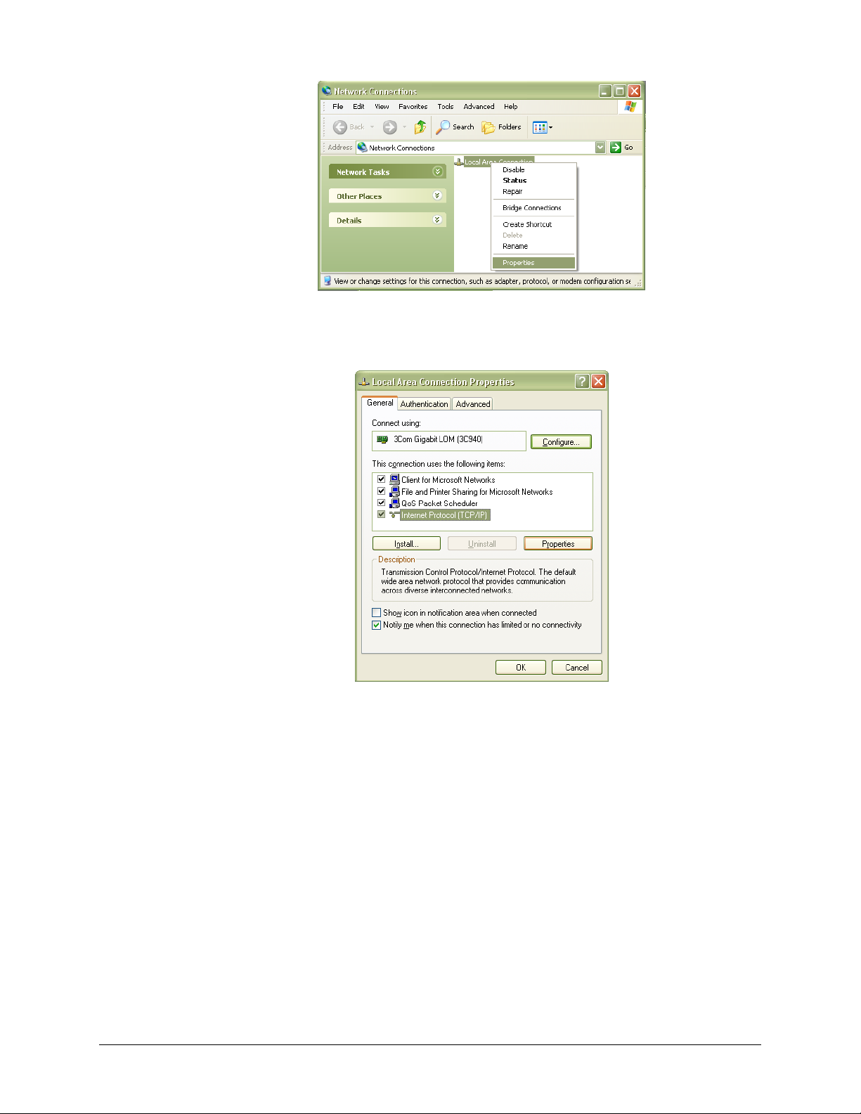
www.vtiinstruments.com
FIGURE 2-9: NETWORK CONNECTION PROPERTIES
4) Select Internet Protocol (TCP/IP), then click the Properties button as shown in Figure 2-10.
FIGURE 2-10: LOCAL AREA CONNECTION PROPERTIES DIALOG BOX
5) Determine if the PC is set to use auto or static IP. Figure 2-11 shows examples of both auto
and static IP address configurations.
EX1629 Preparation for Use 37
Page 38
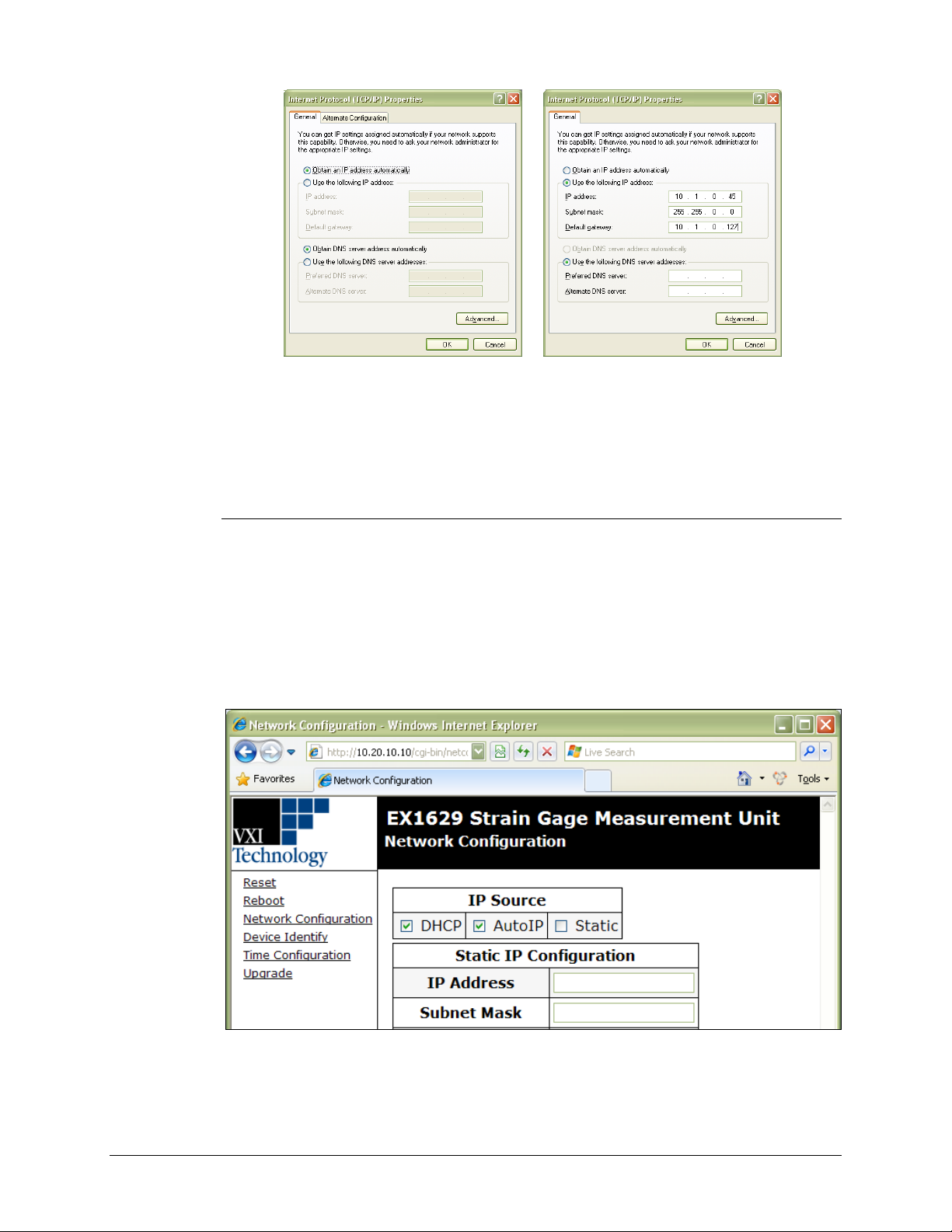
VTI Instruments Corp.
6) If set to use a static IP, record the IP address, subnet mask, and default gateway for use later.
FIGURE 2-11: DYNAMIC (LEFT) AND STATIC (RIGHT) IP ADDRESS CONFIGURATIONS
Select Obtain an IP address automatically to establish a connection to the EX1629. Click
the OK button and proceed to Set the EX1629 to Static IP. If set to use a dynamic IP, click the
OK button and proceed to Set the EX1629 to Auto IP.
Set the EX1629 to Auto IP
1) Remove all network connections from the PC except for the connection to the EX1629.
Wireless adapters should be disabled as well.
2) Apply power to the EX1629 and wait for the LAN LED to turn green.
3) Discover the EX1629 using the LInC-U utility as described in the Web Page Operation in
Section 5. The steps taken previously should ensure that discovery works.
4) Once connected to the EX1629, click on Network Configuration in the command menu.
5) Select DHCP and AutoIP in the IP Address Source field and ensure that Static IP is not
selected. Figure 2-12 shows the proper configuration. Click the Submit button to save all
changes.
FIGURE 2-12: EX1629 SET TO USE AUTO IP
38 EX1629 Preparation for Use
Page 39
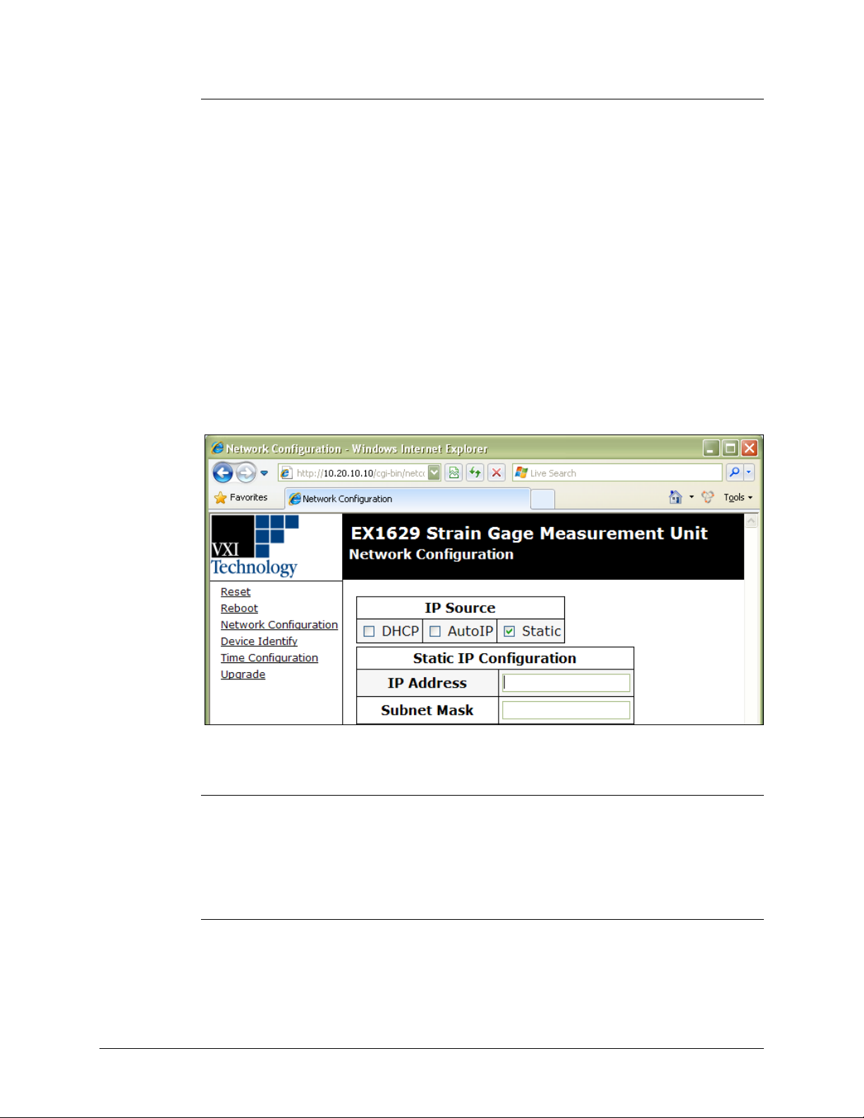
www.vtiinstruments.com
Set the EX1629 to Static IP
1) Disconnect all network connections from the PC except for the connection between the PC
and the EX1629.
2) Apply power to the EX1629 and wait for the LAN LED to turn green.
3) Discover EX1629 using the LInC-U utility as described in the Web Page Operation in
Section 5. The steps taken previously should ensure that discovery works.
4) Once connected to the embedded web interface, click on the Network Configuration link in
the command menu.
5) Select the Static checkbox in the IP Address Source field and ensure that DHCP and
AutoIP are not selected.
6) In the IP Address field, enter an appropriate IP address for the EX1629. Use the IP address
obtained the Determine PCs Network Settings step to determine the network address. The
network address is the first three digits of the IP address (10.1.0 in the example provided).
The last digit of the IP address (the node), is a number, 0 through 255, that is not currently
assigned to any other device on the network. Ensure that a unique IP address is assigned to the
EX1629 by consulting a network administrator.
7) In the Subnet Mask field, enter the subnet mask in the Determine PCs Network Settings step.
8) In the Gateway Address field, enter the same gateway address in the Determine PCs Network
Settings step.
9) Click Submit to save all changes made to the Network Configuration page.
FIGURE 2-13: EX1629 SET TO USE STATIC IP
Restore the Host PCs Network Settings
1) Power down the EX1629 and reconnect it to the LAN in its desired location.
2) If the PC was originally set to use a static IP address, use the procedure in Determine PCs
Network Settings to change the PCs IP address back to its original state.
3) Power on the EX1629 and wait for the LAN LED to turn solid green.
4) Discover the EX1629 using VTI’s LInC-U as described in Web Page Operation in Section 5.
Using Multiple Network Cards
When multiple network cards exist in a single PC, it may be necessary to define a static IP address
to both the host PC NIC card that will interface with the EX1629 mainframe as well as the
EX1629 itself. This process is only necessary if a DCHP server is not connected to the network to
which the device is connected and typically occurs when the NIC is connected directly to the
instrument.
EX1629 Preparation for Use 39
Page 40

VTI Instruments Corp.
The following process can be used to ensure proper functionality.
1) Navigate to Start → Settings → Network Connections.
2) Disable all network interfaces except the one that is connected to the EX1629 mainframe.
3) Open the web page of the EX1629 mainframe.
4) Click the IP Configuration link. A prompt may appear to log into the EX1629 mainframe.
5) Unselect DHCP and AutoIP and ensure that Static is selected.
6) Enter an IP address into the IP Address field. Although any valid network IP address can be
7) Set the Subnet Mask. For this example, the subnet mask is 255.255.255.0.
This is done by right clicking on the interface, then selecting Disable.
used, 192.168.1.2 is used in this example. For more information on valid IP addresses, please
consult with an IT administrator.
FIGURE 2-14: COMPLETED EX1629 MAINFRAME STATIC IP CONFIGURATION
8) Click the Submit button. Once this is done, it is no longer possible to communication with the
EX1629 mainframe. This is normal and is addressed in the following steps.
9) Set a static IP address for the NIC card by doing the following:
a) Navigate to Start → Settings → Network Connections.
b) Right click on the NIC card that the EX1629 mainframe is connected to and select
Properties.
c) Select Internet Protocol (TCP/IP) and click Properties.
40 EX1629 Preparation for Use
Page 41
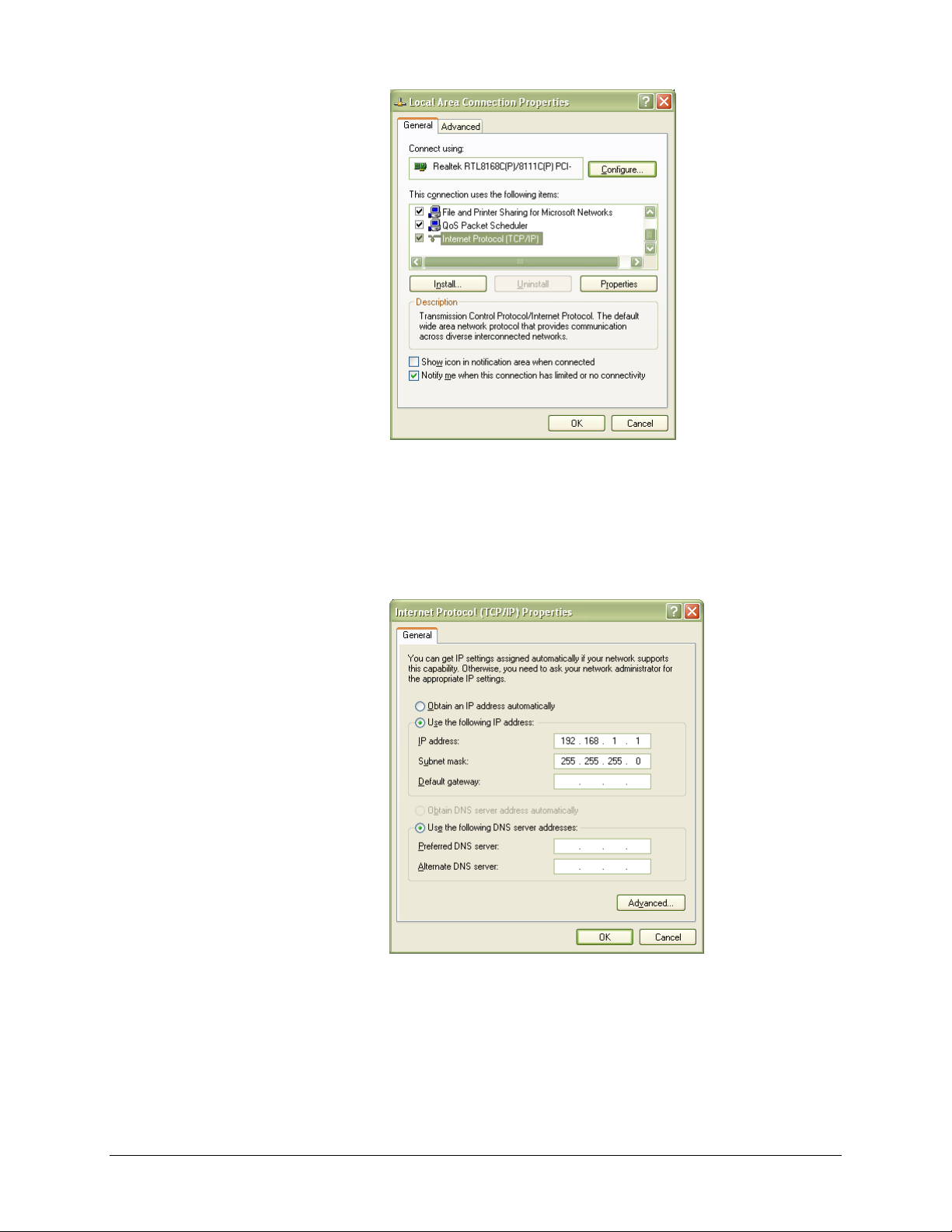
FIGURE 2-15: TCI/IP SELECTION
www.vtiinstruments.com
d) Click the Use the following IP address radio button.
e) Enter the desired IP address. If using the IP from the example above, 192.168.1.1 can be
used.
f) If not automatically completed after the IP address is entered, set the Subnet mask field
to 255.255.255.0.
FIGURE 2-16: COMPLETED NIC STATIC IP CONFIGURATION
g) Click OK to exit the network configuration properties.
PREVENTIVE MAINTENANCE
Although the EX1629 requries no preventive maintainence, it should be operated in laboratory
environments only. The factory calibration should be performed annually, either by VTI customer
EX1629 Preparation for Use 41
Page 42

VTI Instruments Corp.
service staff or by qualified technicans capable of using the optional calibration kit. Selfcalibration is recommended on a monthly basis and should only be performed by qualified
technicians/operators (see Self-Calibration for more information). Should the unit need repair at
any time, it should be returned to VTI Instruments for service.
42 EX1629 Preparation for Use
Page 43
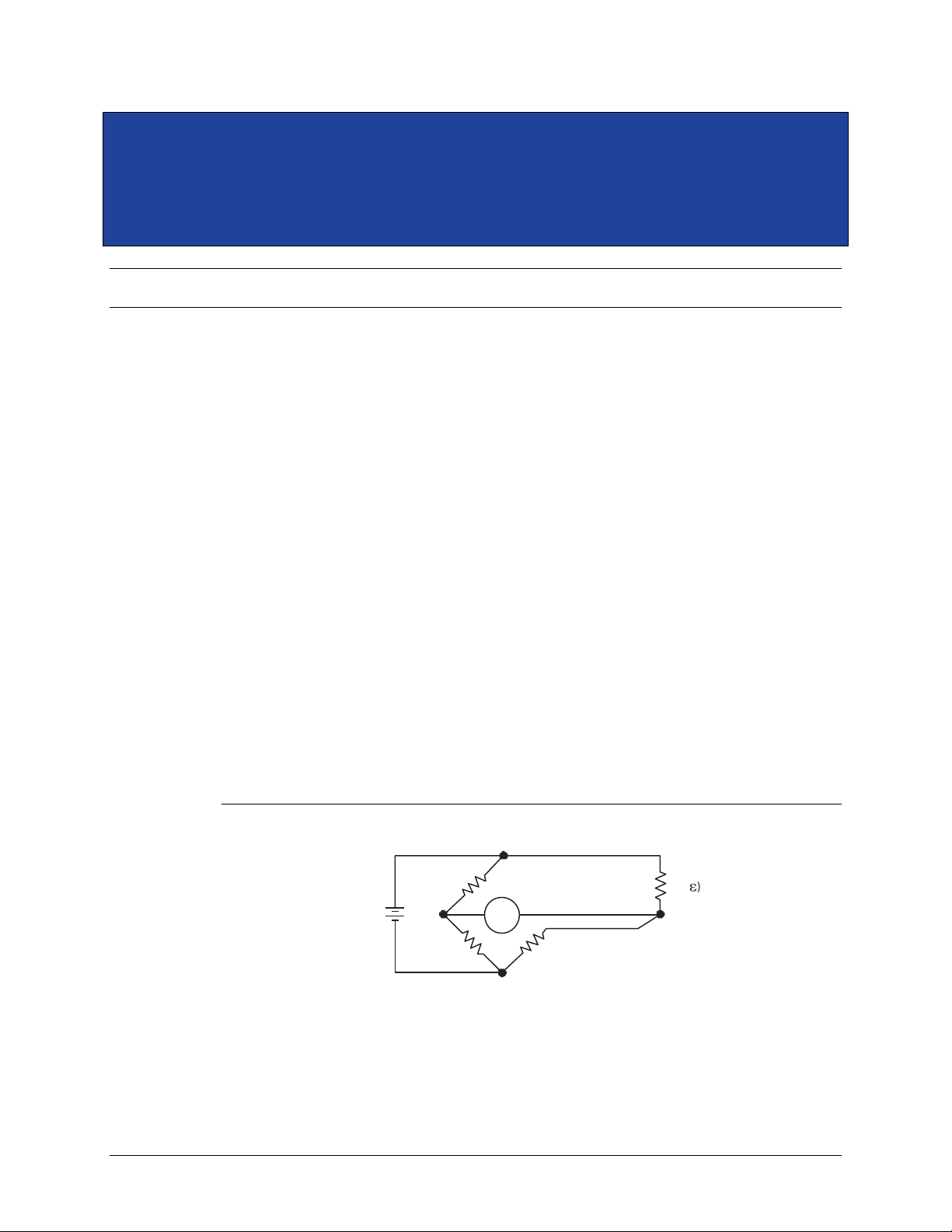
www.vtiinstruments.com
R
com p
R ( )
g
V
OUT
V
EXC
+
–
+
–
R
R
SECTION 3
BASIC OPERATION
INTRODUCTION
This section expands on the description of the EX1629’s features and explains how to best use
them.
ENGINEERING UNIT (EU) CONVERSION
Each EX1629 input channel can be individually configured for one of eleven different preset,
standard EU conversions. Each of these conversions is described below. Setting a specific
conversion not only controls the mathematical operations applied to the acquisition data, but also
automatically configures elements of the signal conditioning path. For example, setting a quarterbridge 350 conversion enables the 350 Ω completion resistor and connects the back-half resistors
to the +Sense measurement line, as illustrated in Figure 2-3. The automatic configuration,
however, can be overridden, as these elements can be configured independently.
Common terms used in the conversion equations are the following:
ε = strain
V
= the voltage sensed from the back-half resistor network
backhalf
V
= the voltage sensed on the –Sense input pin
-sense
V
= the voltage sensed on the +Sense input pin
+sense
V
V
= the unstrained voltage (measured or manually entered)
unstrained
= the excitation voltage (measured or manually entered)
excitation
GF = gage factor
ν = Poisson ratio
Quarter-Bridge 350, Quarter-Bridge 120, Quarter-Bridge User
These conversions apply to the following bridge configuration:
FIGURE 3-1: QUARTER-BRIDGE CONFIGURATION
The specific conversion is selected to match the nominal resistance of the active gage.
EX1629 Basic Operation 43
Page 44
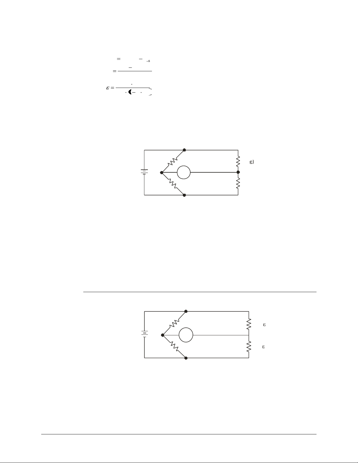
VTI Instruments Corp.
sensebackhalfdiff
VVV
excitation
unstraineddiff
V
VV
V
r
r
r
VGF
V214
V
EXC
R
R
V
OUT
R ( )
g
R (Dummy)
g
R ( )
g
R (Dummy)
g
+
–
+
–
V
OUT
V
EXC
R
R
+
–
+
–
R (+ )
g
R (- )
g
The quarter-bridge strain conversion is calculated according to:
Setting this conversion automatically configures the input path for quarter-bridge mode, in which
the required completion resistor is enabled and the back-half resistors are connected. This
configuration is illustrated in Figure 2-3.
Any of these quarter-bridge conversions also apply to the following bridge configuration, where
the dummy gage is utilized for temperature compensation of the active gage:
FIGURE 3-2: QUARTER-BRIDGE WITH DUMMY GAGE
This is simply a quarter-bridge configuration where the completion resistor is external to the
instrument (since only one leg of the bridge is active, it is a quarter-bridge, not a half-bridge which
would contain two strain gage resistors). To configure a channel for this use, the channel’s EU
conversion should be set to quarter-bridge (any of the 120, 350, or User configurations can be
used, since the nominal resistance only effects which completion resistor is selected), the input
multiplexer should be set to half-bridge, and then the completion resistor should be set to full.
While this configuration appears similar to a half-bridge configuration, it is different in that the
quarter-bridge conversion equation is used. This configuration may be used with any external
completion resistor.
Half-Bridge Bending
This conversion applies to the following bridge configuration:
FIGURE 3-3: HALF-BRIDGE BENDING CONFIGURATION
44 EX1629 Basic Operation
Page 45
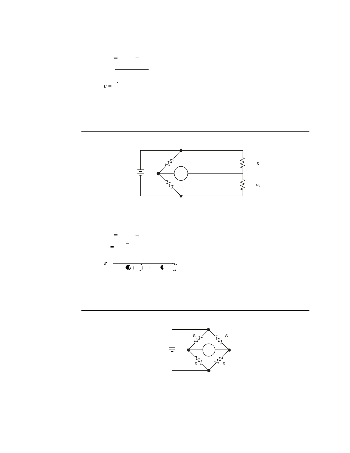
www.vtiinstruments.com
sense-backhalfdiff
VVV
excitation
unstraineddiff
V
VV
V
r
GF
Vr2
R (+ )
g
R (- )
g
V
OUT
V
EXC
R
R
+
–
+
–
sense-backhalfdiff
VVV
excitation
unstraineddiff
V
VV
V
r
121
4
r
r
VGF
V
V
EXC
+
+
–
+
–
+
–
–
V
OUT
The half-bridge strain conversion is calculated according to:
Setting this conversion automatically configures the input path for half-bridge mode, in which the
completion resistor is shorted and the back-half resistors are connected. This configuration is
illustrated in Figure 2-4.
Half-Bridge Poisson
This conversion applies to the following bridge configuration:
FIGURE 3-4: HALF-BRIDGE POISSON CONFIGURATION
The half-bridge strain conversion is calculated according to:
Setting this conversion automatically configures the input path for half-bridge mode, in which the
completion resistor is shorted and the back-half resistors are connected. This configuration is
illustrated in Figure 2-4.
Full-Bridge Bending
This conversion applies to the following bridge configuration:
FIGURE 3-5: FULL-BRIDGE BENDING CONFIGURATION
EX1629 Basic Operation 45
Page 46
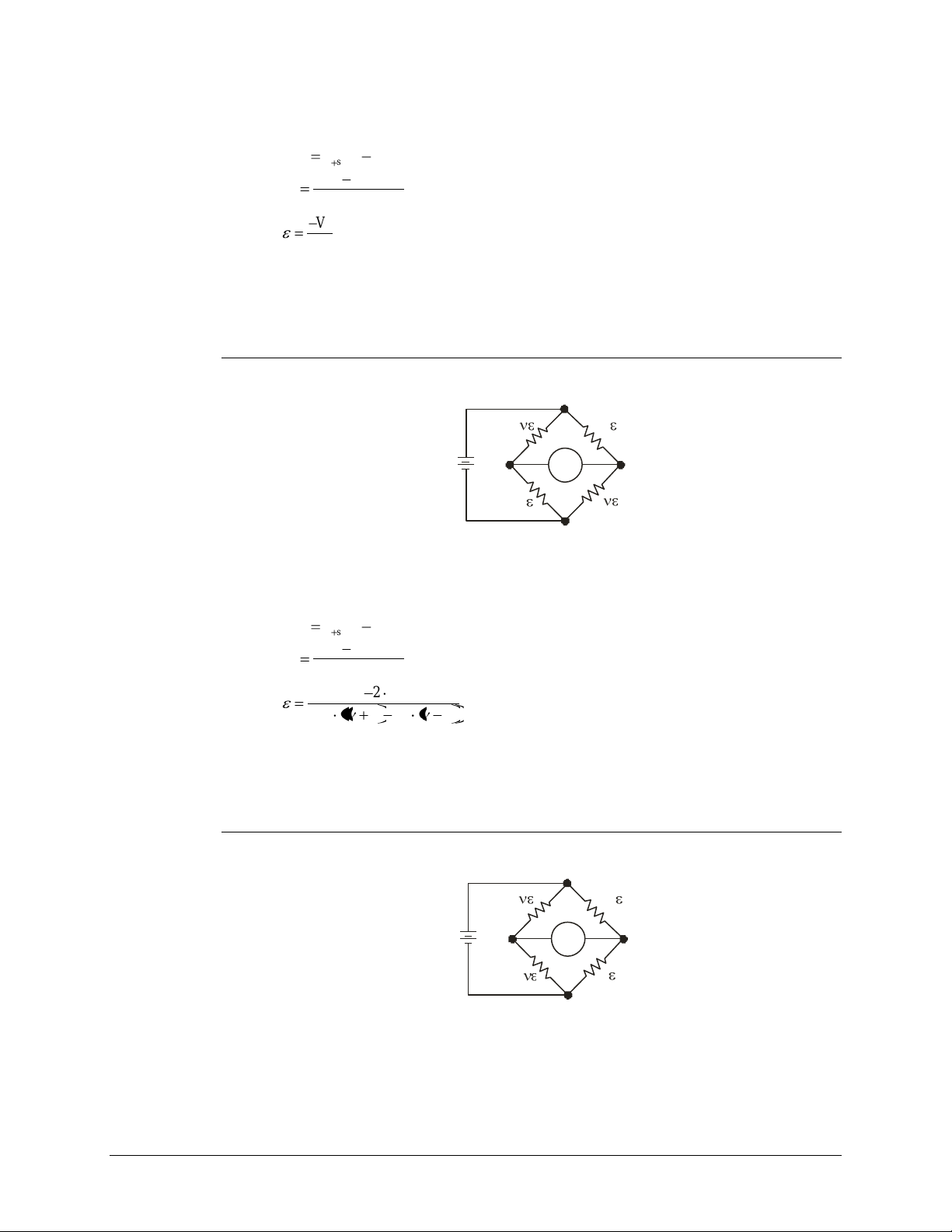
VTI Instruments Corp.
sense-sensediff
VVV
excitation
unstraineddiff
V
VV
V
r
GF
V
r
+
+
–
+
–
+
–
–
V
OU T
V
EXC
sense-sensediff
VVV
excitation
unstraineddiff
V
VV
V
r
11
2
r
r
VGF
V
+
+
–
+
–
+
–
–
V
OUT
V
EXC
The full-bridge strain conversion is calculated according to:
Setting this conversion automatically configures the input path for full-bridge mode, in which the
completion resistor is shorted and the back-half resistors are disconnected. This configuration is
illustrated in Figure 2-5.
Full-Bridge Poisson
This conversion applies to the following bridge configuration:
FIGURE 3-6: FULL-BRIDGE POISSON CONFIGURATION
The full-bridge strain conversion is calculated according to:
Setting this conversion automatically configures the input path for full-bridge mode, in which the
completion resistor is shorted and the back-half resistors are disconnected. This configuration is
illustrated in Figure 2-5.
Full-Bridge Bending Poisson
This conversion applies to the following bridge configuration:
FIGURE 3-7: FULL-BRIDGE BENDING POISSON CONFIGURATION
46 EX1629 Basic Operation
Page 47
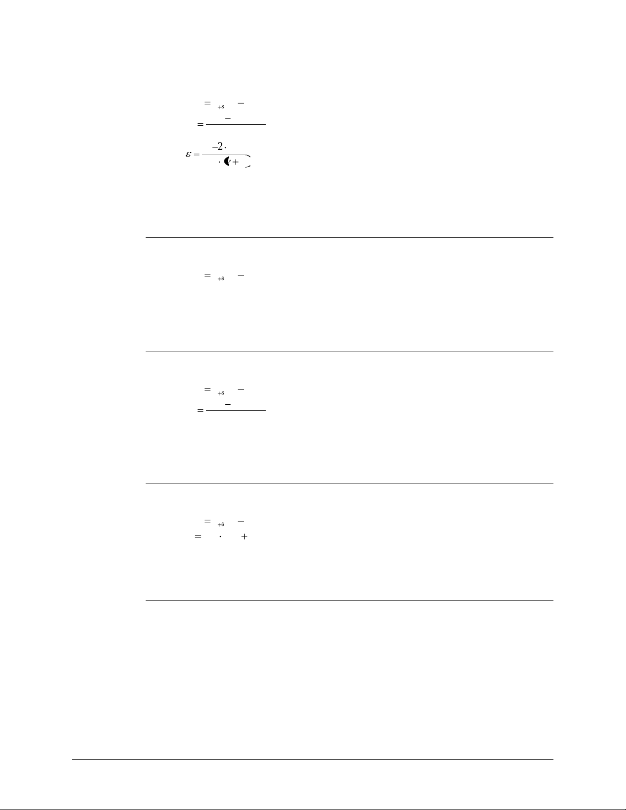
www.vtiinstruments.com
sense-sensediff
VVV
excitation
unstraineddiff
V
VV
V
r
1
2GFV
r
sense-sensediff
VVV
sense-sensediff
VVV
excitation
unstraineddiff
V
VV
V
r
sense-sensediff
VVV
unstraineddiff
VVGFV
The full-bridge strain conversion is calculated according to:
Setting this conversion automatically configures the input path for full-bridge mode, in which the
completion resistor is shorted and the back-half resistors are disconnected. This configuration is
illustrated in Figure 2-5.
Voltage
This simply returns the differential voltage, V
diff
.
Setting this conversion automatically configures the input path for full-bridge mode, in which the
completion resistor is shorted and the back-half resistors are disconnected. This configuration is
illustrated in Figure 2-6.
Ratiometric
This performs a scaling of the differential voltage, V
, according to:
diff
Setting this conversion automatically configures the input path for full-bridge mode, in which the
completion resistor is shorted and the back-half resistors are disconnected.
Linear
This performs a scaling of the differential voltage, V
, according to:
diff
Setting this conversion automatically configures the input path for full-bridge mode, in which the
completion resistor is shorted and the back-half resistors are disconnected.
Nonstandard
As previously mentioned, there are potentially desirable configurations that are not covered by the
standard conversions. An example of this is a quarter-bridge configuration that provides voltage
output instead of strain. Fortunately, the EX1629 provides the flexibility to create virtually any
bridge measurement configuration. Creating a nonstandard EU conversion begins by selecting the
standard conversion that provides the desired conversion equation. Following that, the nominal
settings of the completion resistor and input multiplexer can be changed to fit the requirements of
the application.
The default selection is voltage.
EX1629 Basic Operation 47
Page 48
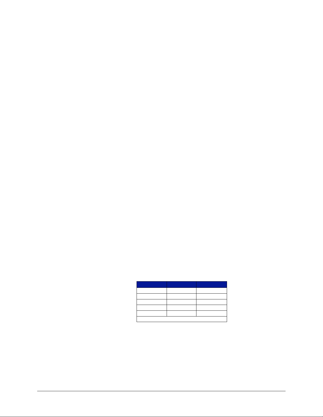
VTI Instruments Corp.
Setting
(+) Input
(-) Input
full
+Sense
-Sense
half
back-half
-Sense
quarter
back-half
-Sense
cal‡
cal source
cal source
gnd‡
ground
Ground
‡
For factory use only.
COMPLETION RESISTOR
In a standard quarter-bridge strain application, the completion resistor value must match the
nominal resistance of the active strain gage. The required completion resistor is normally enabled
through the appropriate setting of the EU conversion. For example, setting a quarter-bridge 350
conversion automatically enables the 350 Ω completion resistor. However, there are potentially
desirable configurations that are not covered by the standard conversions. An example of this is a
quarter-bridge configuration that provides voltage output instead of strain (this is sometimes
useful as a “sanity” check). In that case, the completion resistor must be specifically configured.
Creating a nonstandard EU conversion begins by selecting the standard conversion that provides
the desired conversion equation. Following that, the nominal settings of the completion resistor
and input multiplexer can be changed to fit the requirements of the application.
The available settings for the completion resistor are full, 120, 350, user, and off. 120 and 350
refer to the 120 Ω and 350 Ω resistor paths. Full refers to a low-impedance connection between the
–excitation source and the –Excitation connection (Pin 2 of the input connector). The typical
resistance in full mode is 125 mΩ. User refers to the user-specified resistor path, which may be
populated as a factory option. Off refers to the disabling of all of the resistor paths.
The default value of the completion resistor is full.
INPUT MULTIPLEXER
The connection of the EX1629’s signal conditioning circuitry is governed by the setting of its
input multiplexer, which connects the measurement path to the input measurement lines (±Sense),
the back-half resistors, the calibration source, or ground. The required input multiplexer
configuration is normally controlled through the appropriate setting of the EU conversion. For
example, setting a quarter-bridge 350 conversion automatically configures the input multiplexer
for quarter mode, as shown in Figure 2-3. However, there are potentially desirable configurations
that are not covered by the standard conversions. An example of this is a quarter-bridge
configuration that provides voltage output instead of strain. In that case, the input multiplexer
must be specifically configured.
Creating a nonstandard EU conversion begins by selecting the standard conversion that provides
the desired conversion equation. Following that, the nominal settings of the completion resistor
and input multiplexer can be changed to fit the requirements of the application.
The available settings for the input multiplexer are shown in Table 3-1, mapped to the specific
connections of the instrumentation amplifier inputs.
TABLE 3-1: INPUT MULTIPLEXER SETTINGS
48 EX1629 Basic Operation
The default value of the input multiplexer is full.
Page 49
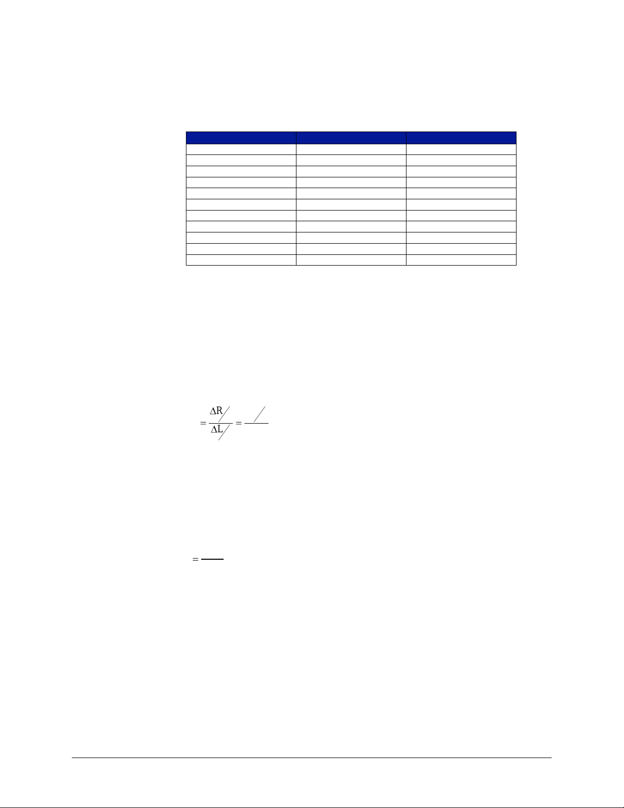
COMPLETION RESISTOR/INPUT MULTIPLEXER DEFAULT SETTINGS
EU Conversion
Completion Resistor
Input Multiplexer
Voltage
Full
Full
Quarter 120 Ω
120 Ω
Back-half
Quarter 350 Ω
350 Ω
Back-half
Quarter User
User
Back-half
Half Bending
Full
Back-half
Half Poisson
Full
Back-half
Full Bending
Full
Full
Full Poisson
Full
Full
Full Bending Poisson
Full
Full
Ratiometric
Full
Full
Linear
Full
Full
ε
R
ΔR
L
L
R
R
GF
long
trans
ε
-ε
ν
Table 3-2 contains the default input multiplexer and completion resistor values for each EU
conversion.
TABLE 3-2: DEFAULT COMPLETION RESISTOR/INPUT MULTIPLEXER VALUES
GAGE FACTOR / POISSON RATIO
As illustrated in the Engineering Unit (EU) Conversion subsection, there are two constants
utilized in the EU strain conversions: gage factor and Poisson ratio.
www.vtiinstruments.com
The gage factor (GF), a measure of strain gage sensitivity, is a dimensionless quantity defined as
the ratio of the fractional change in resistance to the fractional change in length along the primary
axis of the strain gage. Mathematically, this is expressed as:
The gage factor value for a specific strain gage is provided by the strain gage manufacturer. The
default gage factor is 2.0.
The Poisson ratio (ν), in simple terms, is a measure of the extent to which a material contracts as it
is being stretched. In engineering terms, it is a dimensionless quantity defined as the ratio of
transverse contraction strain to longitudinal extension strain in the direction of the stretching force.
Mathematically, this is expressed as:
The Poisson ratio value for a specific material should be obtained from a mechanical engineering
reference. The default Poisson ratio is 0.3.
EX1629 Basic Operation 49
Page 50
VTI Instruments Corp.
Bridge Configuration
Excitation
Range
Quarter
10 V
+30927 µε/-29126 µε
Quarter
5 V
+63829 µε/-56603 µε
Half
10 V
±15000 µε
Half
5 V
±30000 µε
Full
5 V
±15000 µε
Full
2.5 V
±30000 µε
MEASUREMENT RANGE / GAIN
Each EX1629 input channel can be individually configured with respect to its signal conditioning
gain. The differential voltage measurement range of the EX1629 is ±150 mV, ±1.5 V, or ±15 V,
for gain settings of 100, 10, and 1, respectively. As strain measurements will nearly always be
conducted at a gain of 100, its measurement range is primarily a function of bridge configuration
and excitation voltage level. The extent of initial bridge imbalance, which is reflected in the
unstrained voltage measurement, is a secondary factor, but it is normally not large enough to be
significant. Nominal measurement ranges for some common bridge configurations are listed in
Table 3-3.
For quarter-bridge configuration, note that the dynamic range is slightly different for tension vs.
compression. While the dynamic range of the voltage measurement circuitry is a balanced
±150 mV, the transfer function of strain-to-voltage is nonlinear, and that results in the small
disparity.
TABLE 3-3: EX1629 MEASUREMENT RANGE
The default gain setting is 1, although most strain gage measurements are taken using a gain of
100.
EXCITATION SOURCE
Each EX1629 input channel features an independent excitation source that is not only
programmable on a per channel basis, but also with respect to the positive and negative supplies
that compose the total excitation voltage. This programming independence provides the flexibility
of balanced or unbalanced excitation. Specifically, the positive and negative excitation voltages
are programmable from 0 V to +8 V and 0 V to -8 V, respectively, with a total current capability
of 50 mA per channel. Overcurrent protection is 60 mA. Moreover, each source is independently
regulated, such that an overcurrent condition on one channel does not affect the regulation of any
other channels.
The operations to program and enable each excitation voltage are discrete. Excitation voltages that
are not enabled output an actual value of 0 V, regardless of their programmed value.
When the excitation source is changed, the nominal value of the total excitation voltage is updated
in the EU strain conversions. However, for highest accuracy, the excitation voltage should be
measured and the measurement used in the EU conversion (see the Excitation Source
Measurement section that follows). The strain accuracy tables are based on the requirement that
excitation measurement is performed.
For highest accuracy in half-bridge and full-bridge configurations, each excitation source has a
remote sense connection. In order to properly remove the effects of lead wire resistance, these
lines should be connected at the same point that the ±Excitation lines are connected to the bridge.
The remote sense lines are always active in the circuitry; there is no control to turn on/off remote
sense. Because of this, it is critical that they be left open (unconnected) in quarter-bridge
configuration, where their connection would be invalid.
50 EX1629 Basic Operation
Page 51

www.vtiinstruments.com
As explained in Maximizing Measurement Performance in Section 1, because of the relatively
high levels of power dissipation involved, it is best to allow the bridge system elements to
thermally stabilize after an excitation source change. Excitation and unstrained voltage
measurements taken after an appropriate delay will demonstrate improved stability during the
subsequent strain testing.
NOTE For maximum measurement performance, an excitation source change should be followed by a
thermal stabilization delay before the excitation and unstrained voltage measurements are
performed.
The default programmed values for the excitation sources are 0 V. The default enable states for the
excitation sources are off.
EXCITATION SOURCE MEASUREMENT
For highest measurement accuracy, the EX1629 provides the ability to measure its excitation
source and use the measurement in the EU conversion. By doing so, the set point accuracy of the
excitation source ceases to be an error source. The strain accuracy tables are based on the
requirement that excitation measurement is performed.
An excitation source measurement is composed of two confidence system measurements: a
measurement of the +excitation voltage followed by a measurement of the –excitation voltage.
The total excitation voltage is then calculated as (+V
user dictates whether the measurement is used in the EU strain conversions, taking the place of the
nominal excitation value. However, because the measurement system accuracy exceeds the set
point accuracy of the source, overall strain accuracy is always improved by using the source
measurement in the EU conversion.
) – (-V
exc
). Through program control, the
exc
The excitation source measurement also provides control over whether the local sense or remote
sense lines of the excitation source are measured. If the remote sense lines are not connected to the
external strain bridge, such as in quarter-bridge configuration, either setting can be used. The
values in either case are the same. However, if the remote sense lines are connected to the bridge,
as they ideally should be in half- or full-bridge configuration, the remote sense lines should be
measured, as they represent the true source output seen by the bridge.
While a tightly regulated supply, the excitation source does, nonetheless, have a temperature drift
characteristic. For this reason, it is best to conduct the excitation source measurement just prior to
the initiation of strain measurements, making the source measurement as fresh as possible.
Moreover, to achieve maximum performance, it is best to allow the system elements to thermally
stabilize following an excitation source change before conducting its measurement. For more
details, see Maximizing Measurement Performance in Section 1.
NOTE For maximum measurement performance, an excitation source change should be followed by a
thermal stabilization delay before the excitation source measurement is performed.
While measuring the excitation source is the conventional method of providing a non-nominal
value of the excitation voltage to the EU conversion, it is also possible to manually enter a value.
This would normally only be done for system diagnostic purposes.
UNSTRAINED VOLTAGE MEASUREMENT
Integral to strain measurement, the unstrained voltage measurement mathematically removes the
effects of initial bridge imbalance by measuring the bridge voltage with the gage(s) in an
unstrained state and using the resultant value in the EU conversion. For while an unstrained bridge
would ideally have an output of 0 V, component tolerances of the gages and, if employed, the
completion resistor produce a nonzero output. Performing an unstrained voltage measurement
EX1629 Basic Operation 51
Page 52
VTI Instruments Corp.
eliminates these tolerances as an error source. The strain accuracy tables are based on the
requirement that unstrained voltage measurement is performed.
The unstrained voltage measurement should only be taken once the bridge configuration and
excitation source parameters are established. It is critical that the operating conditions under which
the unstrained voltage measurement is taken be identical to those present during strain
measurement. That is, an unstrained voltage measurement taken before an excitation source
change would be mathematically invalid.
NOTE The unstrained voltage measurement should only be taken once the bridge configuration and
excitation source parameters are established.
The EX1629 components responsible for the unstrained voltage are primarily the completion
resistor and the main bridge measurement circuitry. And while they are of extremely high quality,
there is, nonetheless, a small temperature drift characteristic. For this reason, it is best to perform
the unstrained voltage measurement just prior to the initiation of strain measurements, making it as
fresh as possible. Moreover, to achieve maximum performance, it is best to allow the system
elements to thermally stabilize following an excitation source change before conducting its
measurement. For more details, see Maximizing Measurement Performance in Section 1.
NOTE For maximum measurement performance, an excitation source change should be followed by a
thermal stabilization delay before the unstrained voltage measurement is performed.
While measuring the unstrained voltage is the conventional method of providing a value to the EU
conversion, it is also possible to manually enter a value. This would normally only be done for
system diagnostic purposes.
SCAN LIST CONFIGURATION
The EX1629 can be configured to include from 1 to all 48 of its input channels in the scan list.
Because of the channel independence present in the EX1629 design, there are no accuracy, noise,
or speed ramifications from the structure of the scan list. Its channel entries can consequently be
solely dictated by the user’s application requirements. Moreover, since the EX1629 features an
independent A/D converter per channel, input channels are, in a sense, not “scanned” at all.
Instead, the scan list simply dictates the specific data to be returned. The term “scan list” is
borrowed from traditional scanning (multiplexed) data acquisition systems. A valid scan list
consists of:
at least one channel
not more than 48 channels
no repeated channels
Each EX1629 input channel maintains its high input impedance and operational independence
from the other channels regardless of its inclusion in the scan list.
SAMPLING RATE
The EX1629 can be configured for a sampling rate from 1 Sa/s to 10000 Sa/s in 30 discrete
settings, regardless of the number of channels in the scan list. This permits the tailoring of the data
load to the dynamic requirements of the test application. The valid sample rates are 1, 2, 4, 5, 8,
10, 16, 20, 25, 33.33, 40, 50, 80, 100, 125, 166.67, 200, 250, 400, 500, 625, 833.33, 1000, 1250,
2000, 2500, 3125, 5000, 6250, 10000 and 12500 Sa/s. A rate of 25000 Sa/s can be achieved if 1)
the number of active channels is limited to a maximum of 16 and 2) all active channels are on the
same analog board (i.e. channels 0 through 15, 16 through 31, or 32 through 47 can be selected).
Requested rates that fall between valid ones are rounded to the closest valid one.
52 EX1629 Basic Operation
Page 53

UNITS
TARE
www.vtiinstruments.com
Unique in its design, the EX1629 features a secondary “confidence” measurement system that runs
in parallel with the main bridge measurement system. This confidence system, if enabled,
produces data at a fixed rate of approximately 500 Sa/s. If the sampling rate is set at or below
500 Sa/s, the confidence system can produce fresh data for every main bridge output reading. If,
however, the sampling rate is set above 500 Sa/s, the returned data will periodically be returned
without confidence data.
The default setting is 1000.
Each EX1629 input channel can be individually configured with respect to the units of its strain
conversions, either strain (ε) or microstrain (µε). The default units setting is strain. The results of
voltage and linear conversions are always in volts, and ratiometric conversions are unitless.
If the tare feature is employed, it should be noted that an entered tare value is unaffected by a
change in the units setting. For example, if a tare value of 100 is entered when the units are
microstrain, it will be considered as 100 µε. If the unit’s setting is then changed to strain, this tare
value will be considered as 100 ε. To avoid this confusion, it is best to set the desired units first
and then enter any tare value.
Each EX1629 input channel can be assigned a tare, or relative, value. The tare value is subtracted
from the nominal conversion results to produce the final readings, yielding measurements that are
referenced to a nonzero point. Tare can be used on strain as well as non-strain EU conversions.
A subtle characteristic of the tare value is that it is not linked to the units setting of the instrument.
For example, if a tare value of 100 is entered when the units are microstrain, it will be considered
as 100 µε. However, if the units setting is then changed to strain, this tare value will be considered
as 100 ε. Similarly, if instead the conversion is changed to voltage, this tare value will be
considered as 100 V. To avoid this confusion, it is best to set the desired EU conversion and units
first and then enter any tare value.
Tare values apply only to main bridge conversions, not to confidence system measurements.
The default tare value is 0.
DIGITAL FILTER
The EX1629 finite impulse response (FIR) filters provide near Nyquist bandwidths as indicated in
Table B-1. The passband ripple for sample frequencies (fs) greater than or equal to 3125 Hz
is -0.01 dB, while it is ±0.001 dB for fs < 3125 Hz. The filters provide an alias rejection of 100 dB
and have linear phase. Some sampling frequencies result in very high attenuation of 60 Hz signals.
The FIR filters are solely a function of sampling and are not user configurable.
Each EX1629 channel can be individually configured with respect to infinite impulse response
(IIR) filtering. The user can select either Butterworth or Bessel type filters, or may choose no IIR
filter. If IIR filtering is turned on, the -3 dB frequencies can be chosen continuously from fs/1000
to fc max as indicated in Table B-1. The order of the filters can be set by the user as well.
Butterworth filters can be set from 0 - 10 and Bessel filters can be set from 1 to 10. When the user
order is specified as 0, the EX1629 calculates the order based on an analog prototype Butterworth
filter with -200 dB attenuation at fs/2, given the sampling frequency and the -3 dB frequency. The
on-board DSP will design IIR filters on-the-fly given a sampling frequency, the -3 dB frequency, a
user order between 1 and 10, the filter type, and the transform.
EX1629 Basic Operation 53
Page 54
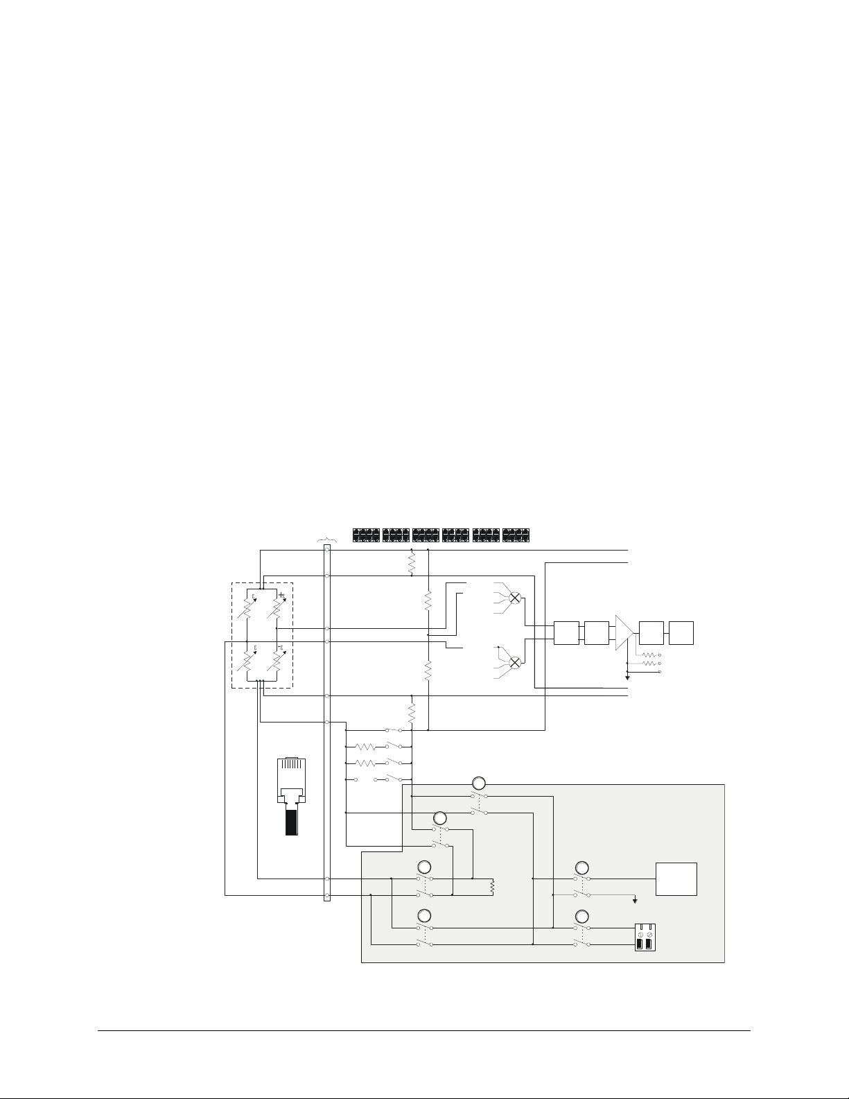
VTI Instruments Corp.
TEDS
COMM
External customer
shunt cal
resistor terminals
Internal
Rcal
55K
-R Cal
+R Cal
Pin 5
Pin 4
Strain
Bridge
8-pin telcom
connector (RJ-45)
350
120
User
10K
10K
+Excitation Sense
+ Excitation
- Excitation
Full-Bridge (1 of 48 channels)
+Excitation
+Sense
-Sense
+Excitation Sense
-Excitation Sense
-Excitation
-Excitation Sense
RJ-45 Pin#
12345678
Pin 2
Pin 7
Pin 6
Pin 3
Pin 8
Pin 1
+
-
-
+
D
C
B
E
F
A
10K
10K
Instrumentation
Amplifier
+
-
x1
x10
x100
Hi
Lo
Shield
150
150
-Sense
-Cal
AGND
+Sense
Wagner
+Cal
AGND
430 kHz
LOW-PASS
FILTER
60.3 kHz
LOW-PASS
FILTER
ADC
TRIFILAR
FILTER
The default settings are: Butterworth filter with -3 dB freq = 10 Hz, bilinear transform, and user
order = 0 (calculated order = 6). More information on filtering can be found in Appendix B.
TRIGGERING
The EX1629 supports a full function trigger model with a separate arm source and trigger source
event structure. For a complete explanation of the trigger model, see Section 4. In summary, an
acquisition sequence is enabled with a trigger initialize function. Measurement data is then
acquired upon the receipt of the programmed arm source event followed by the receipt of the
programmed trigger source event. Trigger and arm source events can be independently
programmed from a variety of sources including Immediate, Timer, Digital I/O, and the Trigger
Bus.
DATA FORMAT
By default, the data returned during data retrieval is limited to the main bridge readings and the
absolute time of scan initiation. If enabled, the EX1629 can also return data from its confidence
measurement system, such as the excitation source voltages and excitation source currents.
SHUNT CALIBRATION
The EX1629 features an extremely capable and fully programmable shunt calibration architecture
to ensure correct bridge performance. Three discrete shunt calibration modes are supported that
can be employed in local and remote connections. Figure 3-8 illustrates the shunt calibration
design.
FIGURE 3-8: SHUNT CALIBRATION CONFIGURATION
54 EX1629 Basic Operation
Page 55
www.vtiinstruments.com
Setting
Usage
Switches
front_panel_remote
1 per 16 channels
A, F
front_panel_local
1 per 16 channels
D, F
internal_remote
every channel
B
internal_local
every channel
C
teds_remote
1 per 16 channels
A, E
Each input channel provides a unique, precision 55 kΩ resistor that can be connected locally
(switch C) for quarter-bridge shunting or remotely (switch B) for full- or half-bridge shunting.
Since there is a resistor per channel, all 48 input channels may be shunted simultaneously.
If an alternate shunt resistor is required, an external resistor may be connected into each of three
front panel connectors, one for each group of 16 input channels. Each resistor may be connected
locally (switches D, F) for quarter-bridge shunting or remotely (switches A, F) for full- or halfbridge shunting. Up to three front panel resistors may be used simultaneously, but not for more
than one channel in each 16-channel block.
For highest accuracy, the value of this external resistor should be precisely known. The connection
resistance characteristic in the specifications refers to the total resistance of the connection
switches. This resistance must be considered in conjunction with the raw resistor value when
determining the theoretical simulated strain of the shunt calibration process. The connection
resistance is the same for local or remote connection.
Finally, the EX1629 offers the ability to read and control a TEDS-equipped remote resistor
(switches A, E) for full- or half-bridge shunting. Up to three TEDS remote resistors may be used
simultaneously, but not for more than one channel in each 16-channel block.
Table 3-4 summarizes the shunt calibration capabilities and the specific connection switches they
utilize.
Shunt calibration configuration involves two discrete and disjoint operations. Each channel is
assigned a shunt calibration mode, as described above. Separately, each shunt is enabled
(connected) or disabled (disconnected).
The default shunt calibration mode is internal_remote. The default shunt enable setting is disabled.
SELF-CALIBRATION
In order to deliver high measurement accuracy over a wide ambient operating temperature range,
the EX1629 provides the ability to perform an instrument self-calibration. During self-calibration,
the input signal conditioning paths are internally disconnected from the input jacks and connected
instead to a calibration bus that is driven by an internal, precision calibration source. Through
measurement of the conditioning paths at multiple calibration source points, software
compensation for circuitry drift since the last full calibration is conducted. Once self-calibration is
performed, the accuracy specifications listed in Section 1 are valid for 30 days and over a ±5 ºC
ambient temperature change. Note, however, that the unit must still undergo a full calibration at
least once a year, regardless of the use of self-calibration.
Self-calibration should be conducted as often as practical, especially if the ambient environment
has changed significantly since the previous calibration. However, fast ambient environmental
changes should ideally be followed by a period of thermal stabilization before conducting selfcalibration to allow the internal circuitry to stabilize to a new thermal operating condition. The
self-calibration process completes quickly and does not require removal of the actual input
connections, making it convenient to run often.
TABLE 3-4: SHUNT CALIBRATION SETTINGS
EX1629 Basic Operation 55
Page 56

VTI Instruments Corp.
Similarly, self-calibration should only be performed after the EX1629 has been allowed to warm
up from a cold start for at least 60 minutes. To protect the user, the instrument will return a
warning if self-calibration is initiated prior to the completion of this warm-up time. However, it is
only a warning and can be overridden by repeating the calibration function. An override would be
completely acceptable, for example, in cases where a) the unit is already fully warmed-up and is
quickly moved from one physical location to another or b) instrument line power is briefly lost
due to a facility power outage.
Self-calibration does not overwrite, modify, or take the place of the instrument’s nonvolatile
calibration constants generated by a full calibration. Instead, it generates an additional set of
calibration constants that are applied to the measurement calculation after the full calibration
constants. By default, self-calibration data is volatile, meaning that it is not saved through
instrument reboots or power cycles. This ensures that the instrument always initializes with
calibration constants generated by a full calibration. This feature is particularly important when the
instrument is being shared among multiple users. Each user is consequently sheltered from the
actions of others.
Despite having the ability to conduct self-calibration at any time, there may be user applications
that require the use of self-calibration, but demand that it create nonvolatile data. The EX1629
supports that operation as well. Once self-calibration is performed, the data can be stored to
nonvolatile memory through a separate function. Similarly, previously stored self-calibration data
can be loaded or cleared from nonvolatile memory.
Self-calibration offers a convenient way to mitigate the effects of time and temperature on the
signal conditioning circuitry of the EX1629, resulting in significant performance improvement.
However, it cannot compensate or correct for potential drift errors caused by an excitation source
change that is not followed by a thermal equilibrium delay. Similarly, any error caused by lead
wire desensitization is outside of the calibration loop and is not eliminated. Finally, the use of selfcalibration does not remove the necessity of excitation source measurement to achieve stated
accuracies. For more details, see Maximizing Measurement Performance in Section 1.
LOCKING
By default, the EX1629 allows unrestricted operation from multiple hosts. While this offers a high
level of user flexibility, there are instances where protected operation is desirable, if not required.
For these applications, the EX1629 can be “locked,” meaning that it will accept function calls
from only the host IP address that issued the lock function call. With the EX1629 in this mode,
other host connections that attempt function calls will be denied.
By design, the locking mechanism is able to be overridden by a secondary host that issues a break
lock function. Thus, the lock provides a warning to other users that the unit is in a protected
operation state, but not absolute security. This allows for instrument recovery if the host or
application should become disabled. Self-calibration requires the acquisition of a lock prior to its
initiation.
CONFIDENCE SCAN LIST CONFIGURATION
The Confidence Measurement System allows several signals within a bridge to be measured, in
addition to the voltage across the bridge (main input channels), including the excitation voltages
and currents. The confidence measurement system is configured by a scanlist, analogous to the
main input channel scanlist, except that, in the case of the confidence measurement system, the
measurements are actually taken sequentially (scanned) by a number of ADCs, whereas the main
input channels each have a dedicated ADC.
56 EX1629 Basic Operation
Page 57

www.vtiinstruments.com
15
30
44
1
16
31
The confidence scanlist contains the list of confidence channels to be measured on each main
input channel. There is a single confidence scanlist for the entire instrument, so all channels in the
main input channel scanlist have the same confidence measurements taken. That is, if there are 16
channels enabled in the main input scanlist, say channels 0 through 15, and the confidence scanlist
is configured with 4 channels, say excitation current (positive and negative) and excitation output
voltage (positive and negative), 64 confidence measurements will be taken (16 x 4).
The confidence system runs at a fixed rate (500 Sa/s), regardless of the sampling rate of the main
input channels, and asynchronously to the main input measurements. Confidence measurement
data is inserted into the same data stream as the main input channel data. When the main input
sampling rate is equal to or less than 500 Sa/s, all scans of data include confidence data. Between
500 Sa/s and 1000 Sa/s, confidence data is included in the scans when available – the data stream
is self-describing a manner such that clients can tell when confidence data is available and when it
is not. Above 1000 Sa/s, the confidence data is not available.
NOTE The key restriction that MUST be enforced is that any confidence scan list that includes
+V_SENSE and -V_SENSE must also include +EXCITEOUT and -EXCITELOW as well.
CONFIGURATION STORAGE
By default, all configuration options on the EX1629 are at factory defaults when the instrument is
powered-on or is reset. The instrument does support the ability to save user configurations to nonvolatile storage, however. This option saves all configuration variables, and automatically restores
them at power-on or reset, instead of using the factory defaults.
To aid developers, the instrument can generate a “digest” (also known as a “hash”) for the
instrument’s configuration. This digest is a statistically unique value, 16 bytes long, that serves as
a signature or fingerprint for the current configuration state of the instrument. By configuring the
instrument with the desired values and then saving the configuration to non-volatile storage, the
configuration will be available whenever the instrument powers on or is reset. Additionally, by
retaining the digest of the configuration when it is stored, an application can quickly verify that the
instrument is configured identically to the desired state, without laboriously retrieving all
configuration variables and verifying them against the desired state.
NOTES 1) The configuration storage (and digest) pertains only to the acquisition configuration of the
instrument (e.g., scanlist, EU conversions, excitation voltages, etc.). Other instrument
configuration, such as network and time configuration are not covered by this mechanism.
2) Due to the way in which the internal configuration state of the instrument is stored, digest
values for the factory default configuration as well as digest values for saved configurations
may change between firmware versions.
WIDEBAND OUTPUT
The wideband output connector carries a buffered image of the main channel signal. It is a single
ended signal, referenced to GND, and shielded to the chassis. The magnitude of this signal is
±15 V. Assmann Electronics’ P/N: AHDS44LL-Z is one example of a mating connector.
FIGURE 3-9: WIDEBAND OUTPUT CONNECTOR
EX1629 Basic Operation 57
Page 58
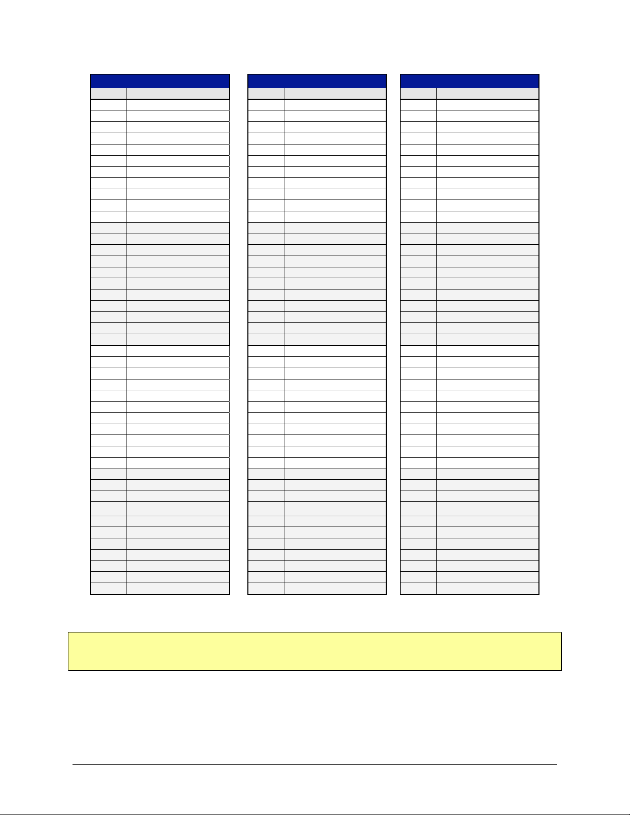
VTI Instruments Corp.
WIDEBAND OUT CH 0-15
WIDEBAND OUT CH 16-31
WIDEBAND OUT CH 32-47
Pin #
Signal
Pin #
Signal
Pin #
Signal
1
CH 7 HI
1
CH 23 HI
1
CH 39 HI
2
CH 6 HI
2
CH 22 HI
2
CH 38 HI
3
CH 5 HI
3
CH 21 HI
3
CH 37 HI
4
CH 4 HI
4
CH 20 HI
4
CH 36 HI
5
CH 3 HI
5
CH 19 HI
5
CH 35 HI
6
CH 2 HI
6
CH 18 HI
6
CH 34 HI
7
CH 1 HI
7
CH 17 HI
7
CH 33 HI
8
CH 0 HI
8
CH 16 HI
8
CH 32 HI
9
CH 15 HI
9
CH 31 HI
9
CH 47 HI
10
CH 14 HI
10
CH 30 HI
10
CH 46 HI
11
CH 13 HI
11
CH 29 HI
11
CH 46 HI
12
CH 12 HI
12
CH 28 HI
12
CH 44 HI
13
CH 11 HI
13
CH 27 HI
13
CH 43 HI
14
CH 10 HI
14
CH 26 HI
14
CH 42 HI
15
CH 9 HI
15
CH 25 HI
15
CH 41 HI
16
CH 7 LO
16
CH 23 LO
16
CH 39 LO
17
CH 6 LO
17
CH 22 LO
17
CH 38 LO
18
CH 5 LO
18
CH 21 LO
18
CH 37 LO
19
CH 4 LO
19
CH 20 LO
19
CH 36 LO
20
CH 3 LO
20
CH 19 LO
20
CH 35 LO
21
CH 2 LO
21
CH 18 LO
21
CH 34 LO
22
CH 1 LO
22
CH 17 LO
22
CH 33 LO
23
CH 0 LO
23
CH 16 LO
23
CH 32 LO
24
CH 15 LO
24
CH 31 LO
24
CH 47 LO
25
CH 14 LO
25
CH 30 LO
25
CH 46 LO
26
CH 13 LO
26
CH 29 LO
26
CH 45 LO
27
CH 12 LO
27
CH 28 LO
27
CH 44 LO
28
CH 11 LO
28
CH 27 LO
28
CH 43 LO
29
CH 10 LO
29
CH 26 LO
29
CH 42 LO
30
CH 9 LO
30
CH 25 LO
30
CH 41 LO
31
CH 7 Shield
31
CH 23 Shield
31
CH 39 Shield
32
Ch 6 Shield
32
Ch 22 Shield
32
Ch 38 Shield
33
CH 5 Shield
33
CH 21 Shield
33
CH 37 Shield
34
CH 4 Shield
34
CH 20 Shield
34
CH 36 Shield
35
CH 3 Shield
35
CH 19 Shield
35
CH 35 Shield
36
CH 2 Shield
36
CH 18 Shield
36
CH 34 Shield
37
CH 1 & CH 0 Shield
37
CH 17 & CH 16 Shield
37
CH 33 & CH 32 Shield
38
CH 8 HI
38
CH 24 HI
38
CH 40 HI
39
CH 15 & CH 14 Shield
39
CH 31 & CH 30 Shield
39
CH 47 & CH 46 Shield
40
CH 8 LO
40
CH 24 LO
40
CH 40 LO
41
CH 13 & CH 8 Shield
41
CH 29 & CH 24 Shield
41
CH 45 & CH 40 Shield
42
CH 12 Shield
42
CH 28 Shield
42
CH 44 Shield
43
CH 11 Shield
43
CH 27 Shield
43
CH 43 Shield
44
CH 10 & CH 9 Shield
44
CH 26 & CH 25 Shield
44
CH 42 & CH 41 Shield
NOTE Wideband output signals should always be measured using an instrument that has true differential
58 EX1629 Basic Operation
TABLE 3-5: EX1629 WIDEBAND OUTPUT PIN ASSIGNMENTS
inputs. If any sensor wires connect to GND, single ended inputs will cause ground loops and
reading errors.
Page 59
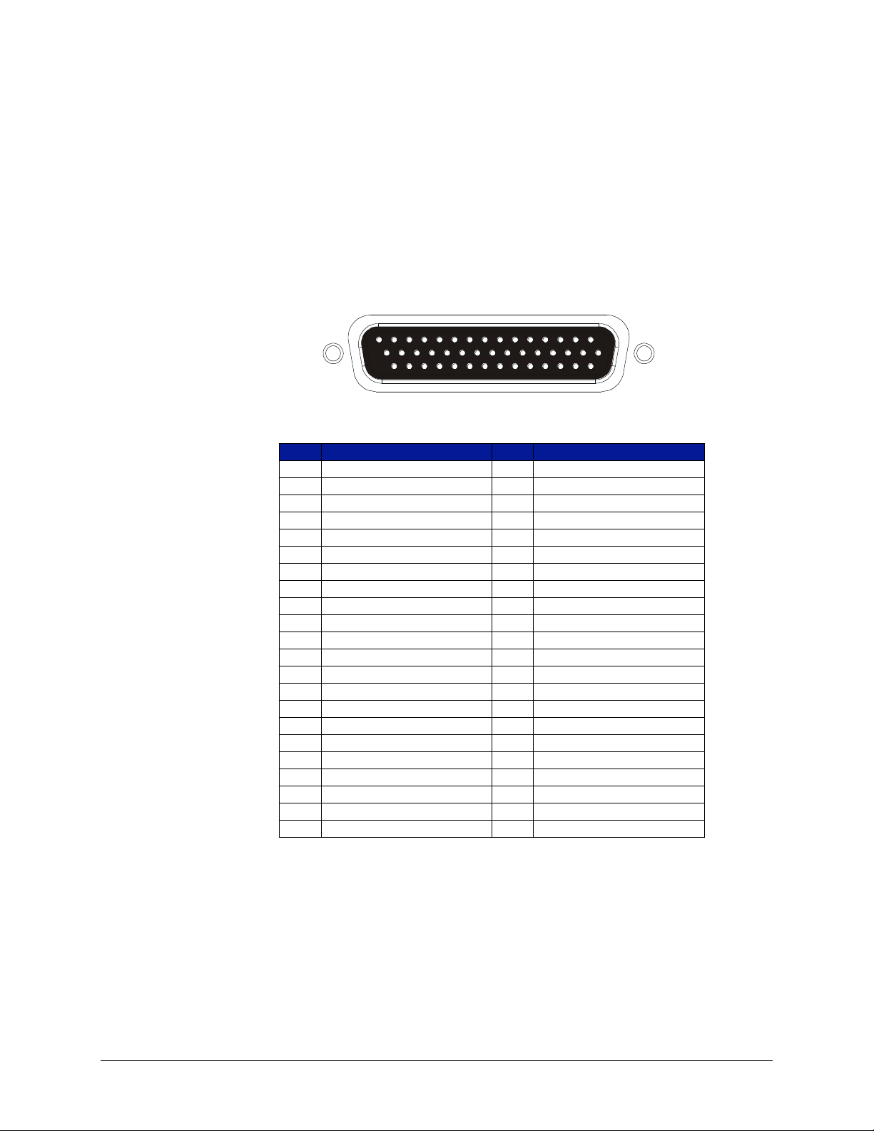
DIGITAL I/O
15
30
44
1
16
31
Pin
Signal
Pin
Signal
1
DIO_BUS0
23
GND
2
DIO_BUS1
24
GND
3
DIO_BUS2
25
GND
4
DIO_BUS3
26
GND
5
DIO_BUS4
27
GND
6
DIO_BUS5
28
GND
7
DIO_BUS6
29
GND
8
DIO_BUS7
30
GND
9
DIO_BUS8
31
DIO_TRIG0
10
DIO_BUS9
32
GND
11
DIO_BUS10
33
DIO_TRIG1
12
DIO_BUS11
34
GND
13
DIO_BUS12
35
GND
14
DIO_BUS13
36
GND
15
DIO_BUS14
37
GND
16
GND
38
GND
17
GND
39
GND
18
GND
40
GND
19
GND
41
GND
20
GND
42
GND
21
GND
43
GND
22
GND
44
DIO_BUS15
www.vtiinstruments.com
The EX1629 provides sixteen programmable digital input/output signals, modeled on the
VT1533A digital input/output signal conditioning plug-on (SCP) module. These sixteen signals
are divided into two banks of 8 signals: Bank 0 is digital I/O signals 0 through 7 and Bank 1 is
digital I/O signals 8 through 15. Each bank is configurable as inputs (default) or outputs. Further,
when configured as outputs, each bank can be configured as a passive (resistor) pull-up or an
active (transistor) pull-up. When configured as inputs, the DIO signals (0 through 15) may be used
as trigger and/or arm sources.
Several vendors provide appropriate mating connectors. AMP part number 216166-1 (44-pin
housing) is one example.
FIGURE 3-10: DIGITAL I/O DB-44 CONNECTOR
TABLE 3-6: DIGITAL I/O CONNECTOR PIN ASSIGNMENTS
EX1629 Basic Operation 59
Page 60
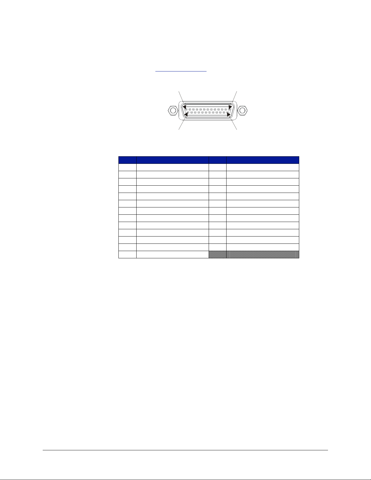
VTI Instruments Corp.
Pin 1 Pin 13
Pin 14 Pin 25
Pin
Signal
Pin
Signal
1
+3.3 V
14
RP_TRIG_P0
2
GND
15
RP_TRIG_N0
3
RP_TRIG_P1
16
RESERVED
4
RP_TRIG_N1
17
RP_TRIG_P2
5
GND
18
RP_TRIG_N2
6
RP_TRIG_P3
19
GND
7
RP_TRIG_N3
20
RP_TRIG_P4
8
GND
21
RP_TRIG_N4
9
RP_TRIG_P5
22
GND
10
RP_TRIG_N5
23
RP_TRIG_P6
11
RESERVED
24
RP_TRIG_N6
12
RP_TRIG_P7
25
RESERVED
13
RP_TRIG_N7
LXI TRIGGER BUS
The EX1629 provides an LXI compatible trigger bus connector. For more information on the LXI
Trigger Bus, please visit www.lxistandard.org and refer to LXI Standard Revision 1.1 and
LXI Trigger Bus Cable and Terminator Specifications Rev 1.1.
FIGURE 3-11: TRIGGER BUS DB-25 CONNECTOR
TEDS TRANSDUCER SUPPORT
TABLE 3-7: LXI TRIGGER BUS CONNECTOR PIN ASSIGNMENTS
The EX1629 supports reading and writing to Transducer Electronic Data Sheets (TEDS) devices
that implement the IEEE 1451.4 standard. Each channel (0 through 47) functions as a 1-Wire bus
master, although only one channel can be active at a time, reading, or writing. Only one TEDS
device per channel is supported.
There are two software interfaces to support TEDS devices, one that is tailored specifically for the
Dallas/Maxim DS2430 part and one that is more general purpose that will work with any 1-Wire
TEDS device, implementing the MicroLAN (MLAN) protocol. The former is deprecated; the
latter, MLAN interface, is more general purpose and should be used by all new applications. The
MLAN protocol is documented in IEEE 1451.4-2004 Annex G. See the MicroLAN (MLAN)
Primer and associated sections for more information.
60 EX1629 Basic Operation
Page 61
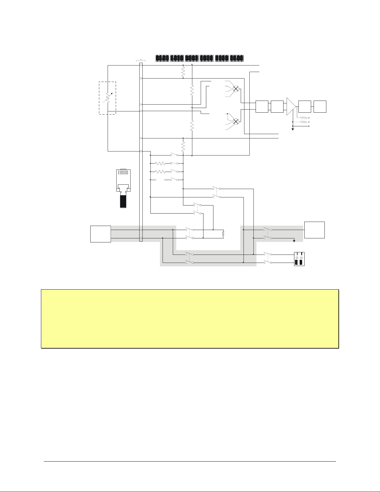
www.vtiinstruments.com
TEDS
COMM
External customer
shunt cal
resistor terminals
Internal
Rcal
55K
-R Cal
+R Cal
Pin 5
Pin 4
TEDS
Device
(i.e. DS2430
or DS2431)
Strain
Bridge
8-pin telcom
connector (RJ-45)
350
120
User
10K
10K
+ Excitation
- Excitation
Quarter-Bridge
(1 of 48 channels)
+Excitation
+Sense
-Sense
+Excitation Sense
-Excitation Sense
-Excitation
+Excitation Sense
-Excitation Sense
RJ-45 Pin#
12345678
Pin 2
Pin 7
Pin 6
Pin 3
Pin 8
Pin 1
IO
GND
10K
10K
Instrumentation
Amplifier
+
-
x1
x10
x100
Hi
Lo
Shield
150
150
-Sense
-Cal
AGND
+Sense
Wagner
+Cal
AGND
430 kHz
LOW-PASS
FILTER
60.3 kHz
LOW-PASS
FILTER
ADC
TRIFILAR
FILTER
NOTE Wiring the TEDS device to the EX1629 may not be as expected given the signal names used. The
RJ-45 Pin 4 (RCAL + / TEDS +) to DS2430/1 GND
RJ-45 Pin 5 (RCAL - / TEDS -) to DS2430/1 IO
The “+” and “-” indicators for the signal names indicate that, since negative voltages are used to
correct wiring is provided above in Figure 3-12 as well as below:
communicate with the TEDS device, the GND signal is actually more positive than the IO signal.
FIGURE 3-12: TEDS WIRING SCHEMATIC
EX1629 Basic Operation 61
Page 62

VTI Instruments Corp.
RESET BUTTON
The reset button on the rear panel of the EX1629, implemented according to the LXI LAN
Configuration Initialize (LCI) Mechanism specification, can be used to restore default network
settings. This is useful for recovery from an incorrect or unknown network configuration. To
perform a network reset:
1) Power off the EX1629.
2) Press and hold the reset button.
3) Power on the EX1629.
4) Continue to hold the reset button for at least 30 seconds.
5) Release the reset button.
The EX1629 will power up as usual, but will use the default network configuration (DHCP and
AutoIP enabled) instead of its previous settings. VXI-11 Discovery (supported by the VISA
IO-Libraries) or the vtex1629_findinstr function can be used to determine the IP address of the
instrument.
62 EX1629 Basic Operation
Page 63
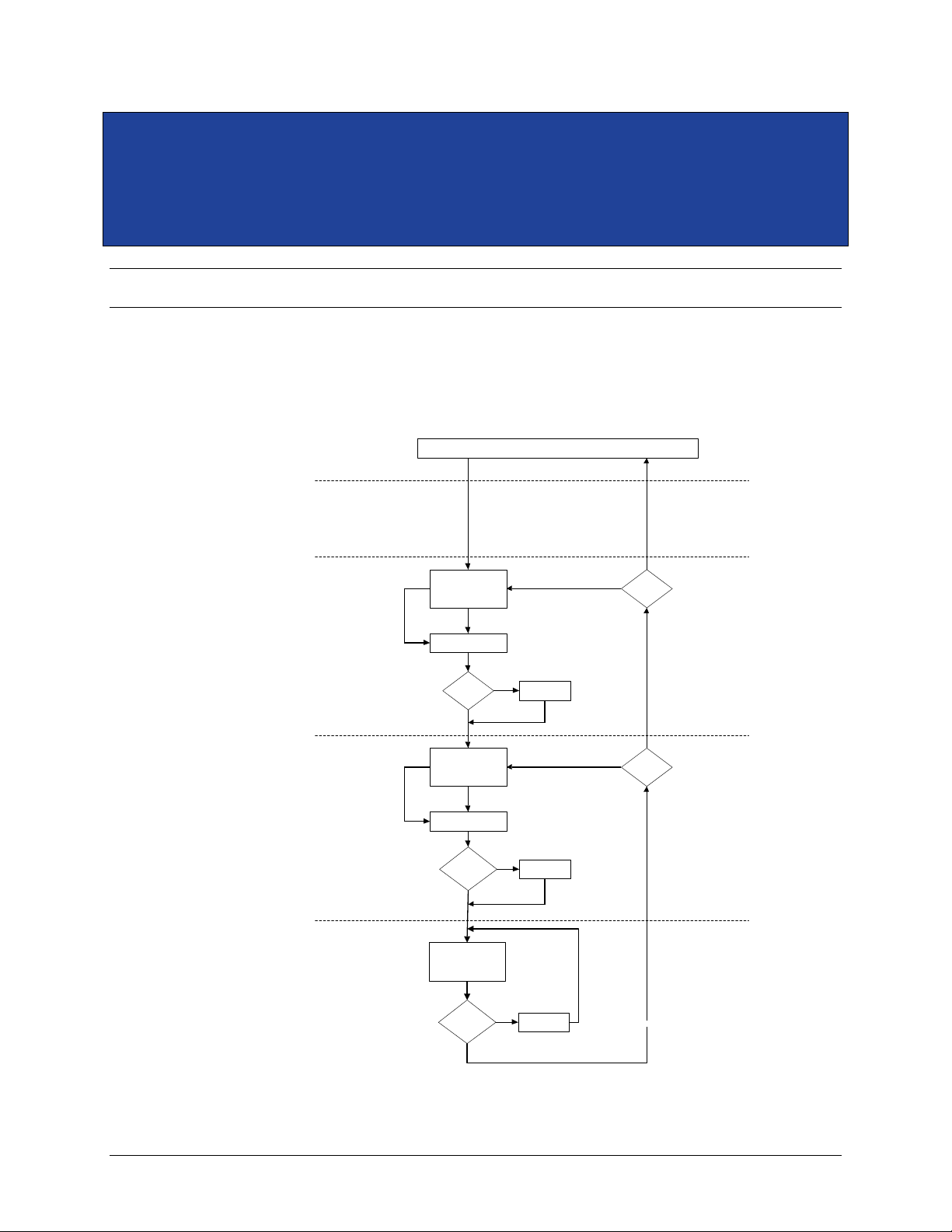
www.vtiinstruments.com
IDLE
IDLE
LAYER
ARM
LAYER
TRIG
LAYER
INIT
LAYER
DEVICE
LAYER
Init
Wait for
ARM Event
ARM Delay
ARM Event
ARM:Count > 0
or
ARM:Count:Inf?
No
Yes
Software Arm
ARM:COUNT:INF?
Decrement
ARM:COUNT
No
Yes
TRIG:Count > 0
or
TRIG:Count:Inf?
No
Wait for
TRIG Event
TRIG Delay
TRIG Event
Software Trigger
TRIG:COUNT:INF?
Yes
Yes
Decrement
TRIG:COUNT
No
Sample Count
Done?
No
Decrement
Sample Count
Yes
Acquire
Data
SECTION 4
TRIGGERING
OVERVIEW
The EX1629 supports a full function trigger model with a separate arm source and trigger source
event structure. The trigger model is based on the industry standard SCPI 1999 Trigger Subsystem
and is diagramed in Figure 4-1.
FIGURE 4-1: EX1629 TRIGGER MODEL
EX1629 Triggering 63
Page 64

VTI Instruments Corp.
The trigger model is sectioned into five layers: IDLE, INIT, ARM, TRIG, and DEVICE. The
EX1629 reset condition places it in the IDLE state. A trigger initialize command begins the
acquisition sequence by transitioning the instrument through the INIT layer into the ARM layer.
As this occurs, the reading buffer memory is cleared
Upon entering the ARM layer, the ARM Count is reset to its specified value. The instrument
remains in the ARM layer until the specified ARM event occurs or a Software Arm is issued.
Once that occurs, the specified ARM Delay (if any) is waited, the ARM Count is decremented,
and the instrument transitions into the TRIG layer.
Upon entering the TRIG layer, the TRIG Count is reset to its specified value. The instrument
remains in the TRIG layer until the specified TRIG event occurs or a Software Trigger is issued.
Once that occurs, the specified TRIG Delay (if any) is waited, the TRIG Count is decremented,
and the instrument transitions into the DEVICE layer.
In the DEVICE layer, channels in the scan list are measured the requested sample count number of
times, and stored into local memory (FIFO).
If the TRIG Count remains nonzero, the instrument stays in the TRIG layer until the specified
TRIG event (and subsequent device action) occurs enough times to decrement it to zero. Once the
TRIG Count reaches zero, the instrument then evaluates the remaining ARM Count and repeats
the ARM layer action if it is nonzero. However, since each transition into the TRIG layer resets
the TRIG Count, each additional ARM layer action results in the full specified number of TRIG
Count actions through the TRIG layer and DEVICE layer.
Once the ARM Count reaches zero, the instrument transitions back into the INIT layer. If Init
Continuous mode is enabled, the ARM layer is automatically reentered without the issuance of a
trigger initialize command. However, unlike with a trigger initialize, the reading buffer memory is
not cleared. Conversely, if Init Continuous mode is disabled, the instrument is returned to the
IDLE layer and requires the issuance of a new trigger initialize command to begin a new
acquisition sequence.
ACQUISITION DATA AND FIFO
When a trigger event occurs and the instrument transitions into the Device Layer of Figure 4-1, a
user-configured number of samples are acquired. Main bridge acquisition data is acquired in
parallel from all channels enabled in the scanlist, using a separate ADC per channel. Acquisition
data, from both the main bridge measurements as well as the confidence subsystem, is captured,
filtered appropriately, calibration compensated, converted to engineering units, and stored in a
FIFO in the EX1629’s RAM along with a timestamp. In parallel, the instrument’s DIO values are
sampled and placed into the FIFO as well.
The digital inputs (DIO) are sampled during acquisition as well. The maximum sample rate for
DIO data is 1 kSa/s. If the main acquisition sample rate is higher than 1 kSa/s, the expected phase
error in terms of samples between DIO & Main bridge shall be ±[Main bridge samp freq/(2*DIO
sample freq)].
To maintain current data within the digital filters, data is always acquired from the main bridge
channels. When not within the Device Layer of Figure 4-1, this data is discarded before it reaches
the RAM FIFO. This serves to keep the digital filter states updated.
Applications may retrieve data from this FIFO using either the Read FIFO or Streaming Data
interfaces. Please refer to the Retrieving Data (Read FIFO and Streaming Data) section for further
details. Once data is retrieved from the FIFO, via either method, it is no longer kept within the
FIFO.
64 EX1629 Triggering
Page 65

CONFIDENCE MEASUREMENT SYSTEM
The Confidence Measurement System runs in parallel with the main bridge measurement system,
but largely asynchronously. The Confidence Measurement System scans the various Confidence
Measurement Sources on each main input channel enabled in the scanlist. This scanning occurs at
the same rate as the main input channel sampling rate, up to 500 Sa/s. Above 500 Sa/s and below
1000 Sa/s, the Confidence Measurement System continues to sample at 500 Sa/s, inserting data
into the FIFO when new data is available. At 1000 Sa/s, confidence data is available with every
other dataset. The confidence data is filtered by a transfer function represented by the following
differential equation: y(n) = 0.01x(n) + 0.99y(n-1), where y(n) is the filtered confidence data and
x(n) is the measured confidence data. This function serves to reduce noise variance.
Confidence data is acquired for every main input channel enabled in the scanlist. Which
confidence data is acquired is controlled by the confidence scanlist. There is only one confidence
scanlist in the system, and thus the same confidence data is sampled for every main input channel.
The amount of confidence data returned is basically the product of the length of the main input
channel scanlist with the length of the confidence scanlist. For example, if the main input scanlist
is configured to measure channels 0, 1, 3, and 5, and the confidence scanlist is configured to
measure +Excite and –Excite, the total number of confidence data values returned will be 8.
To be clear, there is a single FIFO in the EX1629 that holds both main input channel data as well
as confidence measurement system data.
www.vtiinstruments.com
ADC CLOCK AND SYNCHRONIZATION
As was previously described, each input channel is an independent measurement system with its
own synchronous analog to digital converter (ADC). Input data is acquired synchronous to a
sample clock that is distributed to each ADC. In addition to the sample clock, a synchronization
signal is used to reset each of the ADCs and align them to acquire data synchronously. The
triggering system must be re-synchronized each time a change is made to the sample clock source,
sample frequency, or filtering parameters.
LXI LIMIT EVENTS
LXI Limit Events allow the EX1629 to send triggers to other instruments when an over-limit
condition is detected for bridge measurements. Each of the eight LXI Trigger Bus lines can have a
minimum and/or maximum limit defined for any and all of the 48 bridge measurement channels.
When an over-limit condition occurs, the trigger line is driven high. Because the limit comparison
is performed after filtering, the group delay of the chosen filter also delays trigger assertion. When
all filters are disabled and at a sample rate of 1 kSa/s, the typical delay is 14 ms.
Limit events also allow the user to latch their trigger signal. When latching is enabled, the trigger
line is driven high when the first over-limit condition occurs and remains high until the instrument
is reset or until the next measurement sequence is initiated. When latching is disabled, the state of
the trigger line is decided once per scan. When all chosen limit conditions are satisfied, the line is
driven low. Whenever any limits are exceeded, the line is driven high.
EX1629 Triggering 65
Page 66

VTI Instruments Corp.
SYNCHRONIZING MULTIPLE INSTRUMENTS
In cases where larger acquisition systems are required, multiple devices can be configured to
utilize the same ADC sample clock and synchronization signal to acquire data that is synchronized
across all acquisition channels. This requires configuring one of the devices as a master and the
remaining devices as slaves. The devices must be connected together using the LXI Trigger Bus in
either a star or daisy chain configuration. The details of how to program the configuration of
multi-box systems is described in Section 6.
Please refer to Configure Trigger and ADC Clock for further details.
66 EX1629 Triggering
Page 67

www.vtiinstruments.com
SECTION 5
WEB PAGE OPERATION
INTRODUCTION
The EX1629 offers an embedded web page to control network configuration, time configuration,
and firmware upgrades.
OPENING THE WEB PAGE
To open the embedded web page, start the LInC-U utility by navigating to Start → Programs →
VTI Instruments Corporation → LInC-U Utility → LInC-U Utility. Once the utility is run,
LInC-U will scan the network to discover all LAN-based VTI instruments. Once the scan is
complete, the Discovery Devices tab will appear and show the instruments that were discovered,
as shown in Figure 5-1. To open the web page, click on the hostname hyperlink in the Discover
Devices tab. The IP address of the EX1629 can also be viewed from this window as well as its
firmware version.
FIGURE 5-1: LINC-U DISCOVERY TAB WITH EX1629 SELECTED
Alternatively, the IP address of the EX1629 can be entered into the address bar of any web
browser to view the embedded web page. By default, the EX1629 will first attempt to use DHCP
to set its IP Address. If DHCP is not available on the network it is connected to, it will instead use
Auto IP. Determining the Auto IP address is discussed in the Network Configuration discussion in
Section 2. Other discovery methods can be used as well.
EX1629 Web Page Operation 67
Page 68
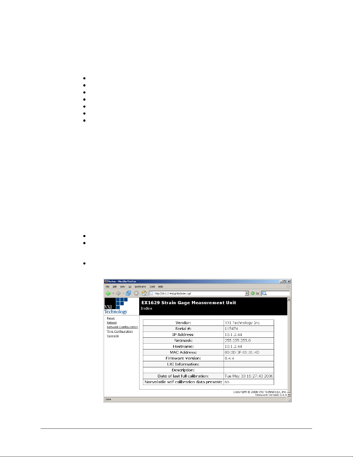
VTI Instruments Corp.
GENERAL WEB PAGE OPERATION
When initial connection is made to the EX1629, the instrument home page, Index, appears. This
page displays instrument-specific information including:
Name
Serial number
IP address
MAC address
Firmware version (also visible in the bottom right corner of every page)
Date of last full calibration
Presence of nonvolatile self-calibration data
This page is accessible from any other instrument page by clicking on the EX1629 web page
header.
The EX1629 command menu is displayed on the left hand side of every internal web page. The
entries on the command menu represent three types of pages:
Status This type of page performs no action and accepts no entries. It provides operational
status and information only. The Index page is an example of a status page.
Action This type of page initiates a command on the instrument, but does not involve
parameter entry. The Reboot page is an example of an action page.
Entry This type of page displays and accepts changes to the configuration of the instrument.
The Time Configuration page is an example of an entry page.
Use of the entry-type web pages in the EX1629 are governed by a common set of operational
characteristics:
Pages initially load with the currently-entered selections displayed.
Each page contains a Submit button to accept newly entered changes. Leaving a page before
submitting any changes has the effect of canceling the changes, leaving the instrument in its
original state.
Navigation through a parameter screen is done with the Tab key. The Enter key has the same
function as clicking the Submit button and cannot be used for navigation.
FIGURE 5-2: EX1629 MAIN WEB PAGE
68 EX1629 Web Page Operation
Page 69
www.vtiinstruments.com
PASSWORD
Pages that modify instrument configuration (e.g., Network Configuration) require a password
login. This mechanism is meant to prevent accidental configuration modification. The default
password is ex1629. Pages that require a password will provide a link to the password login page.
NOTES 1) The instrument password uses lower-case letters.
2) This password mechanism provides only the most basic security. Applications requiring
additional security should consider using private, dedicated subnets, firewalls, etc. to limit
access to the instrument on the network.
VTI INSTRUMENTS LOGO
The VTI Instruments Logo that appears on the upper left of all EX1629 web pages is a link to the
VTI Instruments Corp. corporate website: http://www.vtiinstruments.com.
EX1629 STRAIN GAGE MEASUREMENT UNIT
The title block (“EX1629 Strain Gage Measurement Unit” on a black background at the top of the
page) of all EX1629 Web Pages is a link to the Main Web Page.
RESET
This action page is used to return all of the EX1629’s acquisition configuration parameters to their
default values. It is most commonly used to return the instrument to a known configuration state
prior to the initiation of a new test sequence. Specific affected configuration parameters and their
reset values are documented in Table 6-1. An instrument reset only affects acquisition parameters
and does not affect self-calibration data. This is equivalent to the vtex1629_reset function.
NOTE An instrument reset clears the FIFO reading memory. All desired acquisition data must be
retrieved from the FIFO prior to the issuance of this command.
REBOOT
This action page is used to perform a complete instrument reboot, equivalent to that which occurs
when the instrument is power cycled. It is most commonly used to accept changes that are made to
the network configuration or time configuration settings. In addition, it is suggested that a reboot
be performed before conducting a firmware upgrade.
NETWORK CONFIGURATION
The EX1629 Network Configuration page can be seen in Figure 5-3. By default, the EX1629 will
attempt to locate a DHCP server. If one is found, the IP address assigned by the DHCP server will
be assumed, along with subnet masks, gateway, etc. Otherwise, after a timeout of 20 seconds, the
unit will attempt to obtain an IP address by using AutoIP (IPv4 Dynamic Link Local Addressing).
NOTE The EX1629 can be returned to a known, default network configuration by using the LCI (LAN
Configuration Initialize) Mechanism. See Reset Button for more information.
AutoIP is a mechanism for finding an unused IP address in the IANA assigned range 169.254.X.Y
(169.254/16) where X is in the range 1 - 254 and Y is in the range 0 - 255. The device will first
attempt to obtain the specific address 169.254.X.Y, where X and Y are the second-to-last and last
octets of the device’s MAC address. However, X will be set to 1 if it is 0 in the MAC address, and
to 254 if it is 255 in the MAC address for conformance with the AutoIP specifications. If this
address is already in use, the unit will attempt to obtain other IP addresses in the 169.254/16 range
in a pseudorandom fashion until it finds one that is available.
EX1629 Web Page Operation 69
Page 70
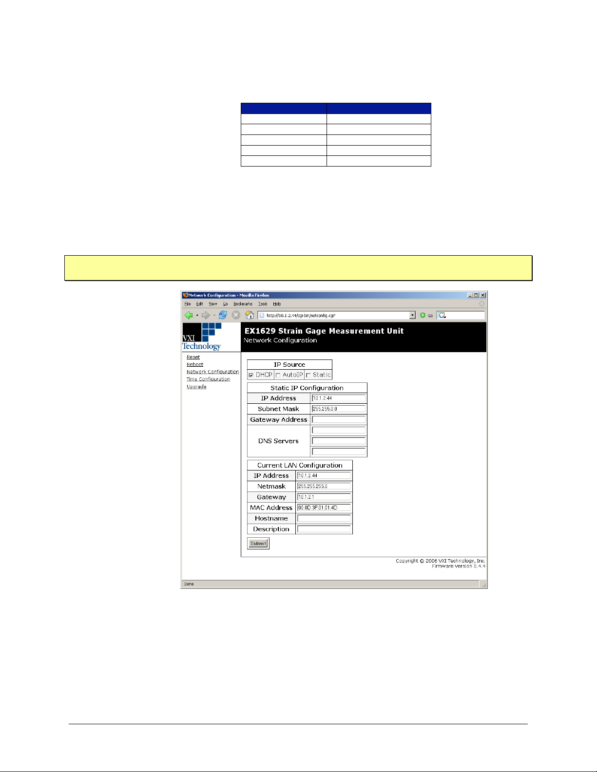
VTI Instruments Corp.
MAC Address
AutoIP Default Address
00:0D:3F:01:00:01
169.254.1.1
00:0D:3F:01:01:01
169.254.1.1
00:0D:3F:01:A3:28
169.254.163.40
00:0D:3F:01:FE:FE
169.254.254.254
00:0D:3F:01:FF:FE
169.254.254.254
To illustrate the AutoIP mechanism, Table 5-1 lists the AutoIP default address for some example
MAC addresses.
TABLE 5-1: AUTOIP DEFAULT ADDRESS ASSIGNMENT
If a static IP address assignment is preferred, one can be optionally assigned via the embedded
web page interface. This is done by clicking the Network Configuration link, disabling DHCP
and AutoIP, enabling Static, and then assigning a static IP address, subnet mask, and gateway
address, and, optionally up to three DNS servers (see Figure 5-3).
NOTE The 169.254/16 subnet is reserved by the IANA for AutoIP usage. It should not be used for either
DHCP or static IP configurations.
70 EX1629 Web Page Operation
FIGURE 5-3: EX1629 NETWORK CONFIGURATION
However, a much more convenient and recommended way to obtain the benefits of a static IP
address is to employ DHCP, but assign the instrument a reserved IP address in your company’s
DHCP server configuration. This reserved address, linked to the EX1629’s MAC address on the
DHCP server, would be assigned to the EX1629 at power up initialization without having to
manually set it on the EX1629. The DHCP server configuration provides a centralized, controlled
Page 71
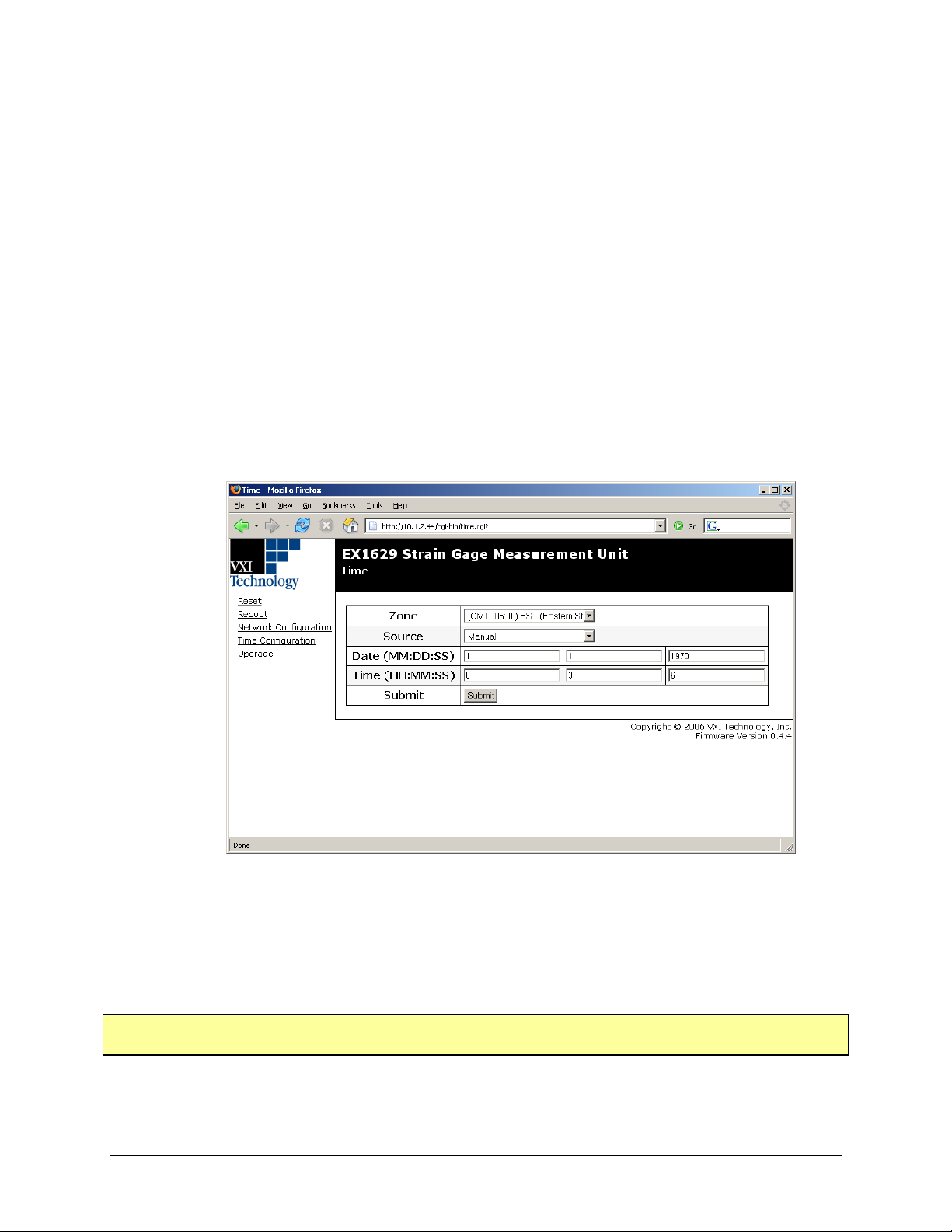
database of assigned IP addresses, preventing accidental assignment of the same IP address to
multiple instruments. Consult your company’s Information Technology department for assistance.
VXI-11 Device Discovery is also supported by the EX1629. This allows all EX1629s on a local
network to be found without knowledge of their MAC address or IP address with the use of a
broadcast message. The vtex1629_findinstr function can be used programmatically to find all
available EX1629 instruments on the LAN.
TIME CONFIGURATION
This entry page is used to change the time configuration of the EX1629. By default, the instrument
has no notion of “wall-clock” or calendar time. The instrument has no battery-backed clock or any
other mechanism to retain time between reboots and power-cycles. By default, the instrument’s
time and date at power-up are midnight, January 1, 1970 (the beginning of the “epoch”). The time
and date can be manually specified on the Time Configuration page (Figure 5-4). Manual
configuration will be necessary if the network environment is such that the instrument cannot
reach the Internet. Manual time entry is not affected by the Zone control and does not require an
instrument reboot to be activated. However, manually-specified time is volatile, and therefore
must be reentered upon an instrument reboot or power cycle. It is not, however, affected by the
Reset page.
www.vtiinstruments.com
FIGURE 5-4: EX1629 TIME CONFIGURATION WEB PAGE - MANUAL
Optionally, the EX1629 supports SNTP (Simple Network Time Protocol), allowing it to receive its
time from an SNTP server. The Zone control provides a pull-down selection in which the user’s
specific time zone is selected. SNTP or NTP (Network Time Protocol) servers are specified in the
Server configuration panel, by IP Address or hostname. An instrument reboot is then required to
activate the new selection.
NOTE Specifying SNTP or NTP servers by hostname requires that the instrument be configured for DNS,
either by DHCP or Static IP.
EX1629 Web Page Operation 71
Page 72
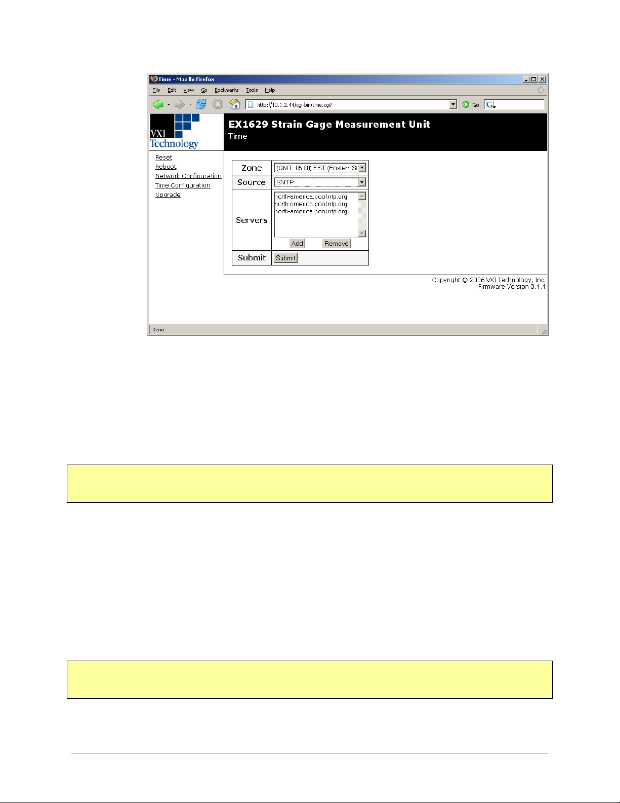
VTI Instruments Corp.
FIGURE 5-5: TIME CONFIGURATION WEB PAGE - SNTP
UPGRADE
This action page is used to upgrade the embedded firmware of the EX1629. Prior to initiating the
firmware upgrade process, a new, uncompressed firmware image must be obtained from
VTI Instruments and be accessible from the computer that is connected to the EX1629. Unless
specifically noted by VTI Instruments, firmware upgrades do not alter the calibration or nonvolatile configuration settings (network configuration, time configuration) of the EX1629.
NOTE Do not power cycle the EX1629 during the firmware upgrade process. If power is lost during the
upgrade, the instrument may be put into an inoperable state, requiring return to the factory. An
uninterruptible power supply may be used to avoid this risk.
Perform the following steps to conduct a firmware upgrade:
1) Perform a Reboot or a power cycle.
2) Connect to the EX1629 via the embedded web page.
3) Click on the Upgrade link.
4) Click on the Browse button and select the firmware image file to be uploaded to the
instrument.
5) Click the Submit button to initiate the upgrade process.
The upgrade process takes approximately 5 minutes to complete, culminating with an automatic
instrument reboot. Once the reboot is complete, reconnect and confirm on the Index page that the
firmware revision level has been properly updated.
NOTE Due to the way in which the internal configuration state of the instrument is stored, digest values
for the factory default configuration, as well as digest values for saved configurations, may change
between firmware versions.
72 EX1629 Web Page Operation
Page 73
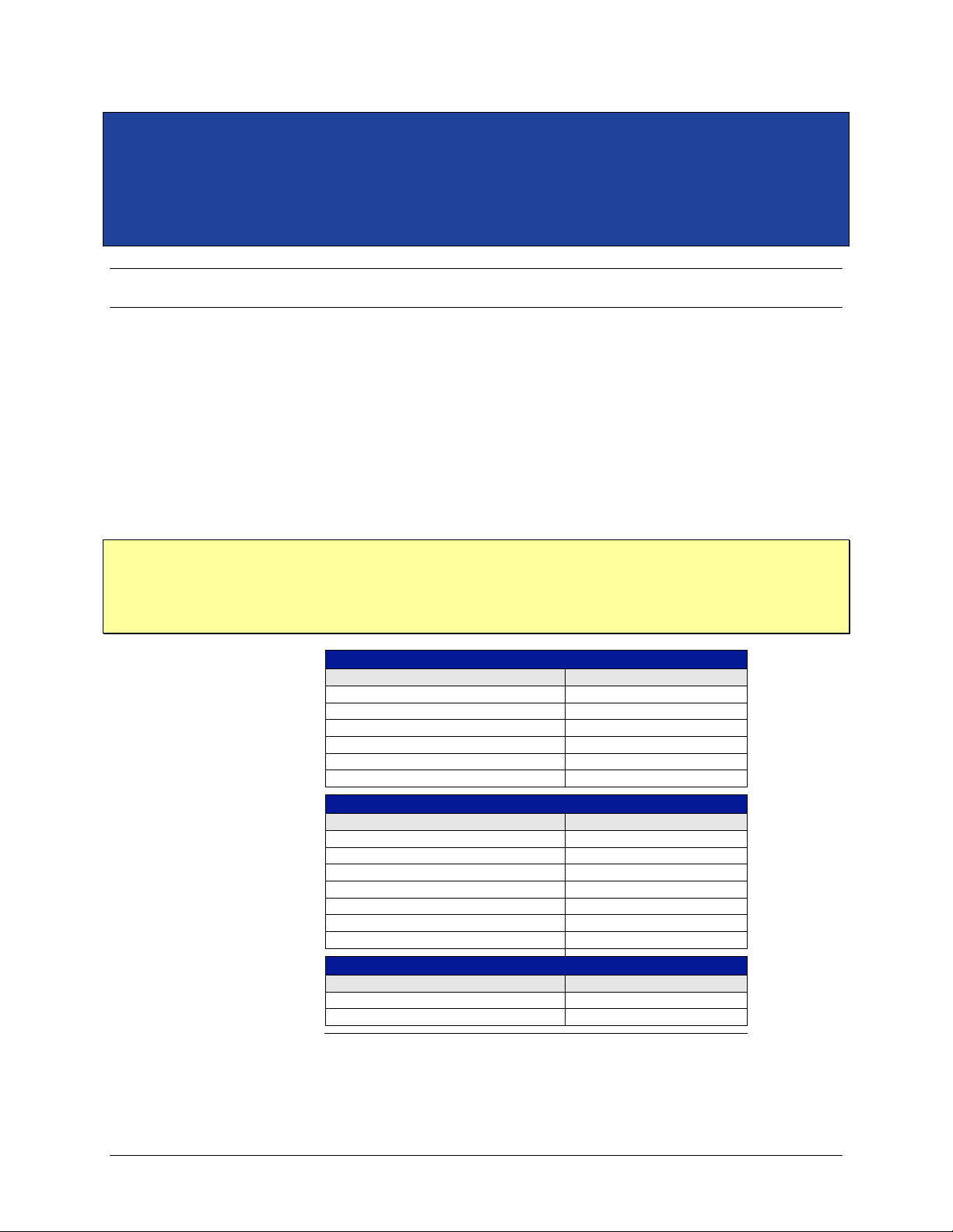
www.vtiinstruments.com
SCAN LIST CONFIGURATION RESET VALUES
CONFIGURATION PARAMETER
RESET VALUE
Scan List (enabled channels)
0-47
Gain
1
Completion Resistor
Full
Input Multiplexer
Full
Sampling Rate (Sa/s)
1000
Confidence Scan List (elements)
None
EU CONVERSION RESET VALUES
CONFIGURATION PARAMETER
RESET VALUE
EU Conversion
Voltage
Excitation Voltage
0
Unstrained Voltage
0
Gage Factor
2.0
Poisson Ratio
0.3
Strain Units
Strain
Tare Value
0
EXCITATION SOURCE CONFIGURATION RESET VALUES
CONFIGURATION PARAMETER
RESET VALUE
Programmed Value
0
Output Enable
Disabled
SECTION 6
PROGRAMMING
INTRODUCTION
This section provides programming examples and rationale for use with the EX1629. While this is
not an exhaustive list, it provides a basis for the creation of code for several basic operations.
DEFAULT SETTINGS
The factory default instrument settings after an instrument reset or a power cycle are listed in
Table 6-1. Many programming applications do not require parameter changes from the default
settings and can be made far simpler by the elimination of redundant functions. The EX1629 can
be returned to the reset state at any time through the issuance of the vtex1629_reset function call.
NOTE The EX1629 supports saving user-defined configurations to non-volatile storage. If there is a user-
defined configuration stored in non-volatile storage, that configuration is applied after a reset,
power cycle, or use of the vtex1629_reset function. The vtex1629_clear_stored_config function
can be used to remove a configuration from non-volatile storage, after which the vtex1629_reset
function will restore the instrument to the factory defaults.
EX1629 Programming 73
TABLE 6-1: DEFAULT SETTINGS
Page 74
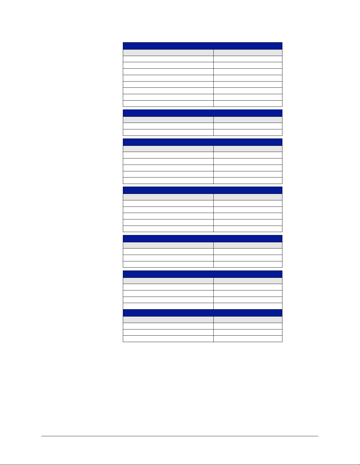
VTI Instruments Corp.
TRIGGER CONFIGURATION RESET VALUES
CONFIGURATION PARAMETER
RESET VALUE
Sample Count
1000
Arm Source
Immediate
Arm Count
1
Arm Delay (seconds)
0
Trig Source
Immediate
Trig Count
1
Trig Delay (seconds)
0
Trig Timer Interval (seconds)
0
SHUNT CALIBRATION CONFIGURATION RESET VALUES
CONFIGURATION PARAMETER
RESET VALUE
Shunt Mode
Internal_remote
Shunt Enable
Disabled
DIGITAL FILTER CONFIGURATION RESET VALUES
CONFIGURATION PARAMETER
RESET VALUE
Type
1 (Butterworth)
Cutoff Frequency (hertz)
10
Transform
0 (Bilinear)
Specified Order
0 (Auto)
Calculated Order
6
DIGITAL I/O CONFIGURATION RESET VALUES
CONFIGURATION PARAMETER
RESET VALUE
Bank 0 Direction
0 (Input)
Bank 0 Pull-up
0 (Passive)
Bank 1 Direction
0 (Input)
Bank 1 Pull-up
0 (Passive)
Output
0
ADC CLOCK RESET VALUES
CONFIGURATION PARAMETER
RESET VALUE
Sample Clock Mode
Master (Standalone)
Sample Clock Input
Internal sample clock line
Sample Clock Output
Internal sample clock line
SYNCHRONIZATION RESET VALUES
CONFIGURATION PARAMETER
RESET VALUE
Synch. Mode
Master (Standalone)
Synch. Input
Internal synch. line
Synch. Output
Internal synch. line
LXI TRIGGER BUS RESET VALUES
CONFIGURATION PARAMETER
RESET VALUE
Direction
0 (Input)
Transmission Scope
1 (External and Internal)
Output
0
74 EX1629 Programming
TABLE 6-1: DEFAULT SETTINGS (CONTINUED)
Page 75

OPENING AN INSTRUMENT SESSION
Prior to performing any programmatic actions with an instrument, a session must be opened. The
following sample code illustrates this using the EX1629 VXIplug&play driver, along with
querying the revision of the instrument driver and instrument firmware.
Sample Code
ViStatus result = VI_SUCCESS;
ViChar instrrev[256];
ViChar driverrev[256];
ViChar filename[256];
ViSession vi;
ViChar errDescription[256] = "";
/* open a session */
result = vtex1629_init(instr, VI_ON, VI_ON, &vi);
if(result != VI_SUCCESS) {
vtex1629_error_message(vi, result, errDescription);
printf(errDescription);
}
/* query the driver and firmware revision */
result = vtex1629_revision_query(vi, driverrev, instrrev);
if(result != VI_SUCCESS) {
vtex1629_error_message(vi, result, errDescription);
printf(errDescription);
}
/* display results */
printf("Driver Revsion: %s\n", driverrev);
printf("Instrument Firmware Revision: %s\n", instrrev);
www.vtiinstruments.com
Note that in the sample code above, error code checking and handling is included. The structure
used above can be used as a template for all functions. In the examples that follow, error code
checking and handling has not been included for brevity.
CLOSING AN INSTRUMENT SESSION
In order to release system resources, applications should close instrument sessions when finished
with them. The following code illustrates this.
Sample Code
/* close the instrument session*/
result = vtex1629_close(vi);
CONFIGURING THE ACQUISITION CHANNELS
Configuration of the EX1629 is an application-specific process. The following sample code,
however, will satisfy many applications and may serve as a template. The sample code does the
following:
Configures the scanlist to contain all 48 channels
Configures all channels for quarter-bridge 120 Ω strain gage EU (which also configures the
input multiplexer and completion resistors appropriately)
Sets the gain to 100X (most sensitive)
Disables the IIR filters
Sets the excitation voltage to ±2.5 V, and enables the excitation supplies
Sets the sampling rate to 100 Sa/s
EX1629 Programming 75
Page 76

VTI Instruments Corp.
Measures the unstrained voltage and updates the unstrained EU conversion variables
Measures the excitation voltage with the confidence subsystem and updates the excitation EU
Sample Code
conversion variables
#define MAX_NUM_CHANNELS 48
ViStatus result = VI_SUCCESS;
ViInt32 channels[MAX_NUM_CHANNELS];
ViInt32 numberOfChannels = MAX_NUM_CHANNELS;
ViInt32 i, numval;
/* initialize a channel array */
for( i = 0; i < MAX_NUM_CHANNELS; i++ )
channels[i] = i;
/* set the scanlist */
result = vtex1629_set_scanlist( vi, channels, numberOfChannels);
/* set the EU conversion for all channels*/
result = vtex1629_set_EU_conversion( vi,
channels,
numberOfChannels,
VTEX1629_EUCONV_QTR_BRIDGE_120);
/* set the gain */
result = vtex1629_set_gain( vi,
channels,
numberOfChannels,
VTEX1629_GAIN_HUNDRED);
/* set the excitation */
result = vtex1629_set_excitation( vi,
channels,
numberOfChannels,
2.5,
-2.5);
/* enable the excitation */
result = vtex1629_set_excitation_enabled( vi,
channels,
numberOfChannels,
VI_TRUE);
/* turn off the IIR filters */
result = vtex1629_set_IIR_filter_configuration( vi,
channels,
numberOfChannels,
VTEX1629_IIR_FILT_NONE,
0,
VTEX1629_TRANSFORM_BILINEAR,
1 );
/* set the sample frequency */
result = vtex1629_set_sample_frequency( vi, 100.0 );
/* measure the unstrained voltage */
result = vtex1629_measure_unstrained_voltage( vi,
channels,
numberOfChannels,
50,
76 EX1629 Programming
Page 77

www.vtiinstruments.com
NULL,
&numval,
VI_TRUE);
/* measure the excitation voltage */
result = vtex1629_measure_ excitation _voltage( vi, channels,
numberOfChannels, VTEX1629_EXCITE_SRC_REMOTE, 50, NULL, &numval,
VI_TRUE);
Setting Bridge Limits
Once the EX1629’s channels are configured for data acquisition, the user’s can also set limits on
the data being acquired so that, if a minimum or maximum value is exceeded, an error message is
returned.
Sample Code
ViStatus status = VI_SUCCESS;
ViChar errMessage[256];
ViInt32 channels[MAX_NUMBER_OF_CHANNELS];
ViInt32 numChannels = MAX_NUMBER_OF_CHANNELS;
ViReal64 minArr[MAX_NUMBER_OF_CHANNELS];
ViReal64 maxArr[MAX_NUMBER_OF_CHANNELS];
int i = 0;
for(i = 0; i < MAX_CHANNELS; i++) {
channels[i] = i;
}
for(i = 0; i < MAX_NUMBER_OF_CHANNELS; i++) {
minArr[i] = (-2.0);
}
for(i = 0; i < MAX_NUMBER_OF_CHANNELS; i++) {
maxArr[i] = 4.0;
}
status = vtex1629_set_bridge_limit(instrumentHandle,
numChannels,
channels,
minArr,
maxArr);
if(status < VI_SUCCESS){
<inform the user the API call failed>
}
Setting LXI Event Limits
Once bridge limits have been defined, LXI trigger bus lines can be programmed to produce trigger
outputs when any of the limit conditions are tripped.
Sample Code
ViStatus status = VI_SUCCESS;
status = vtex1629_set_lxi_limit_event_enabled(vi, 0, 0xffffffff,
0xffffffff, 0xffffffff);
if(status < VI_SUCCESS){
<inform the user the API call failed>
}
EX1629 Programming 77
Page 78

VTI Instruments Corp.
Lead Wire Compensation
The user can also use the EX1629 to compensate for lead wire for lead wire resistance. This is a
common source of error when making measurements and can be difficult to quantify for large
channel count applications. This work can be simplified by utilizing the EX1629s
vtex1629_measure_lead_wire_resistance function.
Sample Code
status = vtex1629_set_lxi_limit_event_latch(vi, 0x01);
if(status < VI_SUCCESS){
<inform the user the API call failed>
}
ViChar errMessage[256];
ViInt32 numberOfChannels = MAX_NUMBER_OF_CHANNELS;
ViInt32 channels[MAX_NUMBER_OF_CHANNELS];
ViReal64 resistance[MAX_NUMBER_OF_CHANNELS];
ViInt32 sampleCount = 100;
int i = 0;
for(i = 0; i < numberOfChannels; i++) {
channels[i] = i;
}
memset(resistance, 0x00, sizeof(resistance));
status = vtex1629_measure_lead_wire_resistance(instrumentHandle,
numberOfChannels,
channels,
resistance,
sampleCount,
VI_TRUE);
if(status < VI_SUCCESS){
<inform the user the API call failed>
}
CONFIGURE TRIGGER AND ADC CLOCK
The EX1629 supports two general use-cases: standalone (one or more instruments that sample
independently and asynchronously) and master/slave (one master instrument and one or more
slave instruments, sampling synchronously). While the configurations for these two use cases are
similar, the master/slave configuration is slightly more complicated, due to the additional
requirements for distributing clock and synchronization signals to guarantee synchronous, phasealigned acquisition.
ADC Sample Clock
The sample clock configuration options on a standalone device and a master device are very
similar. In each case, the device is configured as a sample clock master and the internal oscillator
is used as the clock source. This sample clock can be distributed within the device and to other
devices using any of the LXI Trigger Bus lines. In the case of a standalone device, the internal
sample clock line can be also used to distribute the clock without the need to use one of the
general-purpose trigger bus lines. This internal sample clock line cannot be used in multi-box
configurations since its distribution is limited to within one device.
78 EX1629 Programming
Page 79

www.vtiinstruments.com
To allow added flexibility for more complicated multi-box configurations, the sample clock can
also be output on one trigger bus line and input on another. This functionality is useful in star
multi-box configurations. For example, the master device can be configured to output the clock on
LXI0. A trigger bus hub can be utilized to receive this clock on LXI0 and distribute it to the
master and slave devices on LXI4. The master device can then be configured to receive its clock
on LXI4 instead of using the clock that it is outputting on LXI0. This allows the master and slave
devices to use the same clock from the trigger bus hub instead of the master using one clock and
the slaves using the same clock but with the added phase delay of the trigger bus hub.
The vtex1629_set_sample_clock_source instrument driver function is used to configure the
sample clock source. For a master or standalone device, the sampleClockMode parameter should
be set to VTEX1629_SAMP_CLK_MODE_MASTER. The outLine parameter specifies the
trigger bus line that is used to output the clock. This can be either one of the trigger bus lines or
can be set to VTEX_LXI_LINE_NONE to use the internal sample clock line. The inLine
parameter specifies what line is used by the device for its ADC clock. This may or may not be the
same as the lines that is specified to output the clock via the outLine parameter. As with the
outLine parameter, specifying an input line of VTEX_LXI_LINE_NONE will instruct the device
to use the internal sample clock line. In the case of a stand alone device that uses the internal
sample clock line, both the input and the output lines are set to VTEX_LXI_LINE_NONE.
If a trigger bus line will be used for distributing the sample clock or for receiving a clock back into
the device from an external source, it must be configured prior to configuring the sample clock.
Regardless of whether the sample clock is only used within the device or if it is distributed to
other devices, the trigger bus line that is used to output the sample clock (specified by the outLine
parameter) must be configured as an output using the vtex1629_set_lxibus_configuration function.
If this line will only be used within the device, the transmission scope for the line should be set to
internal transmission only. If the sample clock output is intended to be driven out on the external
trigger bus, the transmission scope must be set for external and internal transmission. If the sample
clock is input on different trigger bus line than it is output, the input trigger bus line must be
configured as an input with external and internal transmission scope using the
vtex1629_set_lxibus_configuration function. When the internal sample clock line is used,
configuration of the trigger bus lines is not required.
Sample clock configuration on a slave device is much simpler than that of a master device. The
vtex1629_set_sample_clock_source function is used to specify a sampleClockMode parameter of
VTEX1629_SAMP_CLK_MODE_SLAVE as well as indicating the trigger bus line that will be
used to receive the sample clock. The trigger bus line must be configured as an input with external
and internal transmission scope.
ADC Synchronization
Configuration of the ADC synchronization signal is similar to configuration of the ADC sample
clock. Standalone and master devices are similar in that they are both configured with a syncMode
parameter of VTEX1629_SYNC_MODE_MASTER using the vtex1629_set_synch_source
function. As a standalone or master device, synchronization pulses are generated on the specified
synchronization signal line using the vtex1629_soft_synch function. The outLine parameter for
this function is used to specify which trigger bus line is used to output the synchronization signal.
It can either specify one of the trigger bus lines or a dedicated internal synchronization signal line.
As with the ADC sample clock source, the synchronization signal can be configured to only be
used within the device or to be output to other devices using the external trigger bus. To allow
flexibility, the synchronization signal can be received back into the device on a different line than
the one on which it is output. As with the ADC sample clock, any trigger bus lines that are used
for the synchronization signal must be properly configured as inputs or outputs and with the
proper transmission scope before they can be used for the synchronization signal. For a standalone
device, the synchronization signal is typically configured to use the internal dedicated
synchronization signal line by setting both the input and output lines to
VTEX1629_LXI_LINE_NONE.
EX1629 Programming 79
Page 80

VTI Instruments Corp.
The synchronization mode on a slave device is set to VTEX1629_SYNC_MODE_SLAVE and the
trigger bus line that is to be used to input the synchronization signal is specified using the
vtex1629_set_sample_clock_source inLine parameter.
Trigger Source
An EX1629 device can utilize a variety of trigger sources. The simplest is the immediate trigger
source. This causes the trigger state machine to bypass the TRIG layer and automatically begin to
acquire data. The device can also be configured to receive its trigger signal from either the positive
or negative edge transition of one of the LXI Trigger Bus lines. The final, and most complicated,
configuration is to generate a trigger signal based on a specified pattern of conditions. A
standalone device will either utilize an immediate or pattern trigger source. A slave device will
either also utilize an immediate trigger source or will specify a trigger bus line to receive a pattern
trigger source that is generated by a master device. The trigger source is specified using the
vtex1629_set_trigger_source function.
The vtex1629_set_pattern_trig_configuration function is used to configure the trigger pattern for a
master or standalone device that is using a pattern trigger source. This function can be used to
specify a combination of LXI Trigger Bus, digital I/O, timer, and software trigger events that will
generate a trigger event. In addition to the LXI Trigger Bus lines that may be used as pattern
inputs, a trigger bus line must be used to output the pattern trigger events. This line is specified
using the vtex1629_set_pattern_trig_configuration function’s lxiOutput parameter. This output
can either be used within the device or can be output to other devices using the external trigger
bus. As with the sample clock and synchronization signal configurations, the same LXI Trigger
Bus line can be used by the device for its trigger source or another trigger bus input can be
specified using the lxiInput parameter. In most cases, the lxiInput and lxiOutput parameters will
be the same. In a star configuration, however, the trigger event might be output on one LXI
Trigger Bus line and back in on a different trigger bus line.
The vtex1629_set_lxibus_configuration function must be used to configure the lxiOutput line as
an output with either internal only scope (if the signal will only be used within the device) or
external and internal transmission scope (if the line will be output to other devices). If the lxiInput
parameter is different from the lxiOutput parameter, the trigger bus line specified by lxiInput
must be configured as an input with external and internal transmission scope. Other LXI Trigger
Bus lines that are used for pattern inputs must be properly configured as inputs with external and
internal transmission scope.
Arm Source
The arm source is configured in the same manner as the trigger source. It utilizes the
vtex1629_set_arm_source and vtex1629_set_pattern_arm_configuration functions.
Standalone (Single Instrument) Example Configuration
The standalone configuration is suitable when only one instrument is required for the data
acquisition or if synchronization of multiple instruments is not required. It uses the instrument’s
internal oscillator for acquisition. The sample code that is provided performs the following tasks:
Sets the number of samples to acquire on a trigger to 100 (one second’s worth with the
100 Sa/s sample rate)
Reset the trigger system to return the trigger bus to its default configuration
Sets the Trigger to Immediate
Sets the Arm to Immediate
Sets the internal ADC clock
Sets the internal ADC synchronization
80 EX1629 Programming
Page 81

www.vtiinstruments.com
Sample Code
ViStatus result = VI_SUCCESS;
/* Configure the system to acquire 100 samples. */
result = vtex1629_set_sample_count( vi, 0, 100 );
/* Reset the trigger system to return the trigger bus to its default
configuration. */
result = vtex1629_reset_trigger_arm( vi );
/* Set the sample clock source as a standalone device using the
dedicated sample clock line. */
result = vtex1629_set_sample_clock_source( vi,
VTEX1629_SAMP_CLK_MODE_MASTER,
VTEX1629_LXI_LINE_NONE,
VTEX1629_LXI_LINE_NONE);
/* Set the synch source as a standalone device using the dedicated
synch line. */
result = vtex1629_set_synch_source( vi,
VTEX1629_SYNC_MODE_MASTER,
VTEX1629_LXI_LINE_NONE,
VTEX1629_LXI_LINE_NONE);
/* Set the arm source to immediate ARM. */
result = vtex1629_set_arm_source( vi, VTEX1629_TRIG_SRC_IMMEDIATE);
/* Set the trigger source to immediate trigger. */
result = vtex1629_set_trigger_source( vi,
VTEX1629_TRIG_SRC_IMMEDIATE);
/* Issue a synchronization signal since the sample clock source was
changed. */
result = vtex1629_soft_synch( vi );
Multiple Instruments (Master/Slave) Example Configuration
The Master/Slave configuration is suitable for larger acquisition systems, up to several thousand
channels (hundreds of instruments). By sharing a single oscillator and utilizing a synchronization
signal from the master, the acquisition of all instruments can be coordinated and phase aligned.
One instrument is assigned the role of “master” and its internal oscillator and synchronization
signals are routed externally via the LXI Trigger Bus. The remaining “slave” instruments are
configured to accept the external clock and synchronization signals from the LXI Trigger Bus.
Through the proper sequencing of instrument driver calls, and the resultant hardware events and
signals, the ensemble of instruments can be made to behave as one large acquisition system, as
illustrated by the sample code below. The following code:
Sets the number of samples to acquire on a trigger to 100 (one second’s worth with the
100 Sa/s sample rate)
Properly configures the LXI Trigger Bus and DIO banks
Sets the ADC clock to master/slave on LXI 0
Sets ADC synchronization to master/slave on LXI 1
Configures a timer trigger on LXI 2
Configures a pattern arm on LXI 3
EX1629 Programming 81
Page 82

VTI Instruments Corp.
NOTE Master/Slave configuration requires the use of LXI Trigger Bus Cables, terminators, and, possibly,
LXI Trigger Bus hubs, switches, or repeaters. Please talk to your application engineer for further
information.
Sample Code
ViStatus result = VI_SUCCESS;
ViInt16 trigLxiLines[4] = {0,0,0,0};
ViInt16 trigDioLines[4] = {0,0,0,0};
ViInt16 armLxiLines[4] = {0,0,0,0};
ViInt16 armDioLines[4] = {0,0,0x09,0x06};
/* Configure the master system to acquire 100 samples. */
result = vtex1629_set_sample_count( master_vi, 0, 100 );
/* Configure the slave system to acquire 100 samples. */
result = vtex1629_set_sample_count( slave_vi, 0, 100 );
/* Reset the trigger system on the slave device to return it to its
default configuration. The slave devices should be reset first to
switch them back to using their internal sample clock oscillators
before changing the configuration of the master.*/
result = vtex1629_reset_trigger_arm( slave_vi );
/* Reset the trigger system on the master device. */
result = vtex1629_reset_trigger_arm( master_vi );
/* Configure the LXI trigger bus lines on the master device. Lines 0
- 3 are external outputs while lines 4 - 7 are outputs that remain
within the device. */
result = vtex1629_set_lxibus_configuration( master_vi,
VTEX1629_LXI_LINE_ZERO,
VTEX1629_LXI_OUTPUT,
VTEX1629_LXI_INTERNAL_EXTERNAL );
result = vtex1629_set_lxibus_configuration( master_vi,
VTEX1629_LXI_LINE_ONE,
VTEX1629_LXI_OUTPUT,
VTEX1629_LXI_INTERNAL_EXTERNAL );
result = vtex1629_set_lxibus_configuration( master_vi,
VTEX1629_LXI_LINE_TWO,
VTEX1629_LXI_OUTPUT,
VTEX1629_LXI_INTERNAL_EXTERNAL );
result = vtex1629_set_lxibus_configuration( master_vi,
VTEX1629_LXI_LINE_THREE,
VTEX1629_LXI_OUTPUT,
VTEX1629_LXI_INTERNAL_EXTERNAL );
result = vtex1629_set_lxibus_configuration( master_vi,
VTEX1629_LXI_LINE_FOUR,
VTEX1629_LXI_OUTPUT,
VTEX1629_LXI_INTERNAL );
result = vtex1629_set_lxibus_configuration( master_vi,
VTEX1629_LXI_LINE_FIVE,
VTEX1629_LXI_OUTPUT,
VTEX1629_LXI_INTERNAL );
result = vtex1629_set_lxibus_configuration( master_vi,
VTEX1629_LXI_LINE_SIX,
82 EX1629 Programming
Page 83

www.vtiinstruments.com
VTEX1629_LXI_OUTPUT,
VTEX1629_LXI_INTERNAL );
result = vtex1629_set_lxibus_configuration( master_vi,
VTEX1629_LXI_LINE_SEVEN,
VTEX1629_LXI_OUTPUT,
VTEX1629_LXI_INTERNAL );
/* Configure DIO bank 0 as inputs on the master device. */
result = vtex1629_set_dio_bank0_direction( master_vi,
VTEX1629_DIO_DIRECTION_IN );
/* Configure the sample clock on the master to output on LXI0. */
result = vtex1629_set_sample_clock_source( master_vi,
VTEX1629_SAMP_CLK_MODE_MASTER,
VTEX1629_LXI_LINE_ZERO,
VTEX1629_LXI_LINE_ZERO );
/* Configure the synch source on the master to output on LXI1. */
result = vtex1629_set_synch_source( master_vi,
VTEX1629_SYNC_MODE_MASTER,
VTEX1629_LXI_LINE_ONE,
VTEX1629_LXI_LINE_ONE );
/* Configure the trigger timer on the master to trigger every 5
seconds. */
result = vtex1629_set_trigger_timer( master_vi, 5 );
/* Configure the trigger pattern to generate an event based on the
timer. */
result = vtex1629_set_pattern_trig_configuration( master_vi,
trigLxiLines,
trigDioLines,
VI_TRUE,
VTEX1629_LXI_LINE_TWO,
VTEX1629_LXI_LINE_TWO );
/* Configure the trigger source on the master as a pattern trigger.
*/
result = vtex1629_set_trigger_source( master_vi,
VTEX1629_TRIG_SRC_PATTERN );
/* Configure the ARM pattern to generate an event on LXI3 when DIO0
and 3 are high and DIO 1 and 2 are low. */
result = vtex1629_set_pattern_arm_configuration( master_vi,
armLxiLines,
armDioLines,
VI_FALSE,
VTEX1629_LXI_LINE_THREE,
VTEX1629_LXI_LINE_THREE );
/* Configure the ARM source on the master as a pattern ARM. */
result = vtex1629_set_arm_source( master_vi,
VTEX1629_TRIG_SRC_PATTERN );
/* Configure the LXI trigger bus lines on the slave device. Lines 0 3 are external inputs while lines 4 - 7 are outputs that remain
within the device. */
result = vtex1629_set_lxibus_configuration( slave_vi,
VTEX1629_LXI_LINE_ZERO,
VTEX1629_LXI_INPUT,
VTEX1629_LXI_INTERNAL_EXTERNAL );
EX1629 Programming 83
Page 84

VTI Instruments Corp.
result = vtex1629_set_lxibus_configuration( slave_vi,
VTEX1629_LXI_LINE_ONE,
VTEX1629_LXI_INPUT,
VTEX1629_LXI_INTERNAL_EXTERNAL );
result = vtex1629_set_lxibus_configuration( slave_vi,
VTEX1629_LXI_LINE_TWO,
VTEX1629_LXI_INPUT,
VTEX1629_LXI_INTERNAL_EXTERNAL );
result = vtex1629_set_lxibus_configuration( slave_vi,
VTEX1629_LXI_LINE_THREE,
VTEX1629_LXI_INPUT,
VTEX1629_LXI_INTERNAL_EXTERNAL );
result = vtex1629_set_lxibus_configuration( slave_vi,
VTEX1629_LXI_LINE_FOUR,
VTEX1629_LXI_OUTPUT,
VTEX1629_LXI_INTERNAL );
result = vtex1629_set_lxibus_configuration( slave_vi,
VTEX1629_LXI_LINE_FIVE,
VTEX1629_LXI_OUTPUT,
VTEX1629_LXI_INTERNAL );
result = vtex1629_set_lxibus_configuration( slave_vi,
VTEX1629_LXI_LINE_SIX,
VTEX1629_LXI_OUTPUT,
VTEX1629_LXI_INTERNAL );
result = vtex1629_set_lxibus_configuration( slave_vi,
VTEX1629_LXI_LINE_SEVEN,
VTEX1629_LXI_OUTPUT,
VTEX1629_LXI_INTERNAL );
/* Configure the sample clock on the slave as an input from LXI0. */
result = vtex1629_set_sample_clock_source( slave_vi,
VTEX1629_SAMP_CLK_MODE_SLAVE,
VTEX1629_LXI_LINE_ZERO,
VTEX1629_LXI_LINE_NONE );
/* Configure the synch source on the slave as an input from LXI1. */
result = vtex1629_set_synch_source( slave_vi,
VTEX1629_SYNC_MODE_SLAVE,
VTEX1629_LXI_LINE_ONE,
VTEX1629_LXI_LINE_NONE );
/* Configure the trigger source on the slave as an input from LXI2.
*/
result = vtex1629_set_trigger_source( slave_vi,
VTEX1629_TRIG_SRC_LXI2_POS );
/* Configure the ARM source on the slave as an input from LXI3. */
result = vtex1629_set_arm_source( slave_vi,
VTEX1629_TRIG_SRC_LXI3_POS );
/* Issue a soft synch command to the master to generate a
synchronization signal since the sample clock source was changed. */
result = vtex1629_soft_synch( master_vi )
84 EX1629 Programming
Page 85

RETRIEVING DATA (READ FIFO AND STREAMING DATA)
The EX1629 stores acquisition data in a large, on-board FIFO in the instruments RAM memory.
48 MB of RAM are reserved for the on-board FIFO. There are two primary mechanisms for
retrieving acquisition data from the EX1629 FIFO:
Read FIFO
Asynchronous Streaming Data
The Read FIFO mechanism is similar to the way data is returned from traditional data acquisition
instruments, with the user application making periodic (polling) queries of the instrument to
retrieve data from the instrument’s on-board FIFO, while asynchronous data streaming is a more
modern, efficient technique, made possible by the instrument’s LXI interface, in which the
instrument automatically transmits acquisition data to the user application as data becomes
available.
The streaming data interface is slightly more complicated to use than the Read FIFO interface, but
makes very efficient use of the host computer’s processor and the test system’s network. As such,
the streaming data interface scales well for high channel count and/or high sample rate systems.
The two data retrieval mechanisms are mutually exclusive – if the streaming data interface is
enabled, Read FIFO requests will return an error.
Read FIFO
www.vtiinstruments.com
Use of the Read FIFO mechanism is straight-forward. After properly configuring the system and
initializing acquisition (vtex1629_trig_init), a user-application queries the instrument’s FIFO for
data using the vtex1629_read_fifo function (or the vtex1629_read_fifoEx function – see below).
This function takes the number of data scans to retrieve as an argument, along with a timeout
value in seconds. The instrument driver attempts to retrieve the requested number of samples from
the instrument, returning to the user-application when either the request has been fulfilled, or the
timeout elapses. To fulfill the request, the instrument driver may need to make many, repeated
queries of the instrument, each query being a network transaction with the instrument. The
instrument driver continues “polling” the instrument for data. During the instrument driver call,
the user-application “blocks”, meaning that the user-application does not continue to the next
instructions until the vtex1629_read_fifo function returns.
Figure 6-1 illustrates the general sequence of events when using Read FIFO. In this diagram, time
flows from top to bottom. The two vertical lines represent the two network nodes: the host
computer, running the user application, and the EX1629 instrument. The diagonal arrows
connecting them represent network messages sent between them (the diagonal arrow, instead of a
horizontal arrow, indicates that the message is not received instantaneously). As illustrated in this
diagram, each instrument driver function call results in two network messages: one to the EX1629
(a request) and one from the EX1629 (a response). The instrument driver function does not return
control to the user application until the response message is received.
As can be seen by the vertical distances, each of the instrument driver function calls takes some
finite amount of time, allowing for host computer processing, network transmission and reception,
and instrument processing. For instrument setup (e.g., configuring acquisition channels or trigger
parameters), this time is typically negligible. For retrieving acquisition data, however, these delays
can become significant. This is especially true in high sample count and/or high channel count
systems. In such systems, the host computer can waste a significant amount of CPU time in these
polling loops, also consuming network bandwidth. The streaming data mechanism offers a more
efficient alternative.
EX1629 Programming 85
Page 86
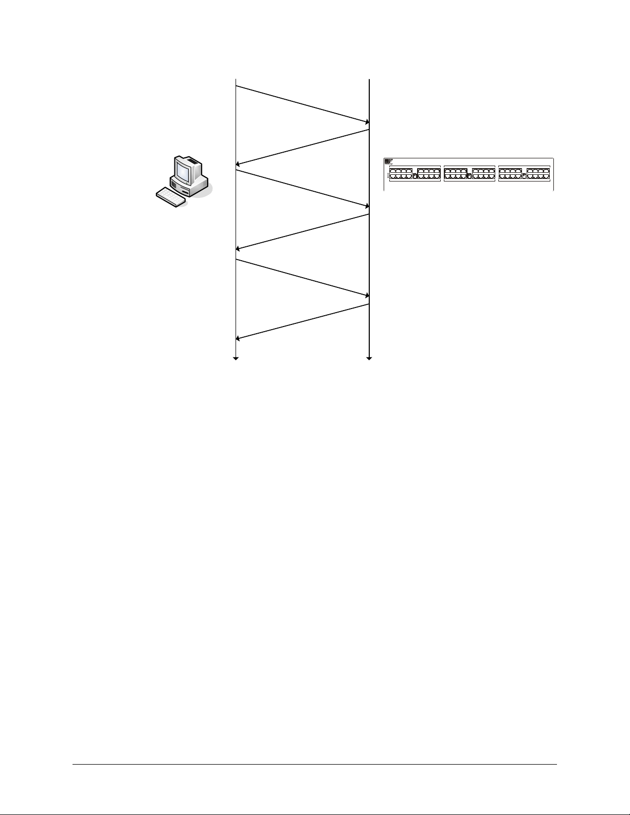
VTI Instruments Corp.
`
Host Computer
EX1629
5 7
0 2
3
HD
LAN
SHUNT
CAL
RES
SHUNT
CAL
RES
SHUNT
CAL
RES
1
4 6
13 15
8 10
11 9
12 14
21 23
16 18
19 17
20 22
29 31
24 26
27 25
28 30
37 39
32 34
35 33
36 38
45 47
40 42
43 41
44 46
PWR
EX1629
time time
Send
:
vtex
1629
_
trig
_
init
()
request
Send
:
vtex
1629
_
read
_
fifo
()
request
Send
:
vtex
1629
_
read
_
fifo
()
request
Receive
:
vtex
1629
_
trig
_
init
()
response
Receive
:
vtex
1629
_
read
_
fifo
()
response
Receive
:
vtex
1629
_
read
_
fifo
()
response
FIGURE 6-1: READ FIFO NETWORK EXAMPLE
The vtex1629_read_fifo function provides access to the main channel acquisition data and
timestamp information. The following code segment illustrates the basic usage of the
vtex1629_read_fifo function, issuing a FIFO query to return 10 scans of data with all 48 channels
enabled. The maximum number of scans to return is specified, as is the maximum number of data
elements to be returned. The acquisition data, along with the timestamp for each scan, is returned
in three arrays of ViReal64 elements, two for the timestamps (seconds and fractional seconds) and
one for the acquisition data. Each scan of data will contain 1 to 48 channels worth of data,
depending on the scanlist configuration. Scan data is returned sequentially within the acqdata
array, so, for the example below, acqdata[0]…acqdata[47] will contain the first scan of data,
86 EX1629 Programming
acqdata[48]….acqdata[95] the second scan of data, etc. The timestamp for the first scan will be
contained in seconds[0] and fractseconds[0], the second timestamp in seconds[1] and
fractseconds[1], etc.
#define NUM_SCANS 10
#define NUM_CHANNELS 48
#define MAX_NUM_SAMPLES (NUM_SCANS * NUM_CHANNELS)
#define TIMEOUT_SECS 5
ViSession vi;
ViReal64 seconds[NUM_SCANS];
ViReal64 fractseconds[NUM_SCANS];
ViReal64 acqdata[MAX_NUM_SAMPLES];
ViInt32 numdata, numscans;
result = vtex1629_read_fifo( vi,
NUM_SCANS,
seconds,
fractseconds,
&numscans,
MAX_NUM_SAMPLES,
Page 87

www.vtiinstruments.com
acqdata,
&numdata,
TIMEOUT_SECS);
The actual number of scans and data returned by vtex1629_read_fifo may be equal to or less than
the values requested (NUM_SCANS and MAX_NUM_SAMPLES in the example) if the timeout
period (TIMEOUT_SECS in the example) expires before the EX1629 has acquired the requested
number of samples. The actual number of scans returned and data values returned are stored in
numscans and numdata, respectively, by vtex1629_read_fifo.
Additionally, there is a vtex1629_read_fifoEx function that provides access to acquisition data
from the confidence measurement system. Please refer to the function references for further
details.
Asynchronous Streaming Data
The asynchronous streaming data interface optimizes communication between the host computer
and the EX1629. The asynchronous streaming data interface allows the EX1629 to transmit
acquisition data to the host computer whenever data is available. It “streams” data to the host
computer – that is the EX1629 transmits data when available – and is “asynchronous” in that data
arrives outside the normal control flow of the user-application. This is in contrast to the Read
FIFO mechanism, where the client polls or queries the instrument for data, and the data is returned
to the user application when the vtex1629_read_fifo function returns (synchronous with the
normal program control flow).
Figure 6-2 illustrates the general sequence of events when using the streaming data mechanism.
This can be compared to Figure 6-1 for using the Read FIFO mechanism. Prior to initiating the
acquisition (vtex1629_trig_init), the streaming data interface must be enabled via the
vtex1629_enable_streaming_data function). This configures the streaming data communication on
both the instrument and the host computer. It is important that the streaming data interface be
enabled prior to initiating acquisition, as the EX1629 prevents streaming data from being enabled
after initiating acquisition. As Figure 6-2 shows, the EX1629 transmits acquisition data to the host
computer periodically, whenever data is available, without the host having to request it.
The streaming data interface uses a separate “socket”, or communications link, than the one used
for other instrument driver functions. Since TCP/IP can support thousands of concurrent sockets,
all multiplexed on the same network interface, this does not present a problem for the network.
NOTE The network communication diagrams provided are oversimplifications. Since TCP/IP is used as
the transport layer, there are potentially several Ethernet packets involved (send and receive) in
each high-level message. These packets provide, among other things, the reliable data transport
feature of TCP.
The asynchronous nature of the streaming data arrival at the host computer presents the issue of
how to deliver the data to the user application. For efficiency, particularly when the acquisition
system consists of many instruments, a multi-threaded model was chosen.
Multi-threaded programming is beyond the scope of this manual, but the general idea is that an
application can have multiple, concurrent “threads” of control. By default, all applications have
one thread, the one that begins executing at the main() function (or similar entry point, depending
on the programming language). Optionally, applications may have additional, programmer created
threads. These threads all execute in the same memory space, making it very efficient for them to
share data. This is different from multi-process programming, wherein each process – basically a
memory space with a single, default thread – executes independently.
Threads execute asynchronously to each other by default – that is, their execution relative to other
threads within the same application (process) is non-deterministic, and shared data must be
EX1629 Programming 87
Page 88
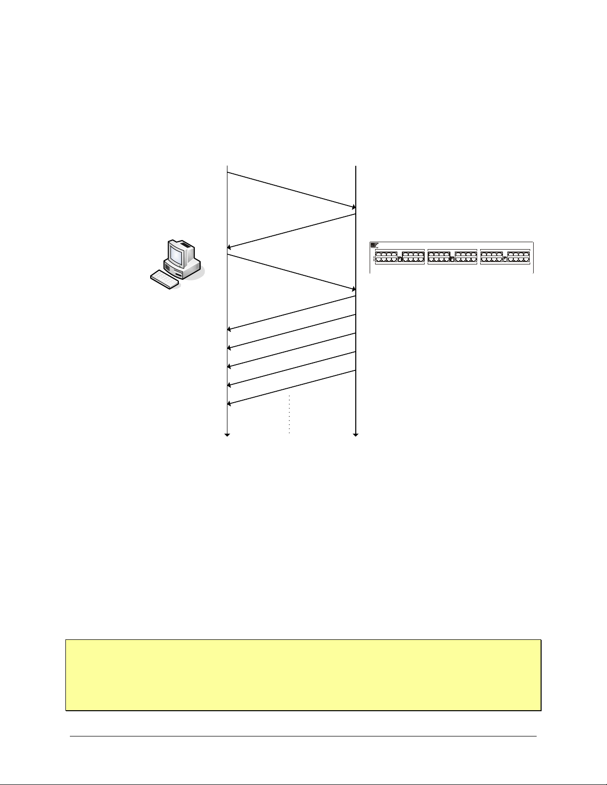
VTI Instruments Corp.
`
Host Computer
EX1629
5 7
0 2
3
HD
LAN
SHUNT
CAL
RES
SHUNT
CAL
RES
SHUNT
CAL
RES
1
4 6
13 15
8 10
11 9
12 14
21 23
16 18
19 17
20 22
29 31
24 26
27 25
28 30
37 39
32 34
35 33
36 38
45 47
40 42
43 41
44 46
PWR
EX1629
time time
Receive streaming data
Receive streaming data
Receive streaming data
Receive streaming data
Receive
:
vtex
1629
_
trig
_
init
()
response
Send
:
vtex
1629
_
enable
_
streaming
_
data
()
request
Receive
:
vtex
1629
_
enable
_
streaming
_
data
()
response
Send
:
vtex
1629
_
trig
_
init
()
request
protected by design or through suitable inter-thread communication mechanisms (e.g., mutexes) to
guarantee consistency. Again, multi-threaded programming is beyond the scope of this manual,
but it is important to understand the fundamentals before the streaming data mechanism can be
used properly. For more information on this topic, we recommend reviewing a textbook on
operating systems (e.g., Operating System Concepts, by Silberschatz, Galvin, and Gagne or
Modern Operating Systems, by Tanenbaum) as well as the Windows SDK information available
online.
FIGURE 6-2: STREAMING DATA NETWORK EXAMPLE
Basic Streaming Data Usage
NOTE Since the callback function executes asynchronously in the same process as the main application
When using the streaming data interface, via the vtex1629_enable_streaming_data function, the
user application provides a callback function. Internally, the instrument driver creates a thread and
then opens a socket for streaming data between the host computer and the instrument. The newly
constructed thread does a “blocking” read on the socket, which causes it to “sleep” (become idle)
until data arrives. When acquisition data arrives, the thread begins executing, receives the
acquisition data from the instrument, executes the user-provided callback function, passing in the
newly arrived data, and then returns to the “sleep” state. The callback function can do whatever is
necessary for the application: write the acquisition values to a file on disk, perform limit checking
on the acquisition values, update an application-specific data structure (e.g., FIFO) post the
acquisition data to a database or spreadsheet, etc. This behavior is illustrated in Figure 6-3, with
the reception of streaming data causing the user-provided callback function to be executed.
thread, it is important that any data or data structures used by both threads are suitably protected to
guarantee consistency. As with any multi-thread application, care must be taken when using interthread communication primitives (e.g., mutexes) to prevent deadlocks and livelocks. Similarly,
performing GUI operations (e.g., updating an on-screen graph) within the callback function needs
to be implemented carefully.
88 EX1629 Programming
Page 89
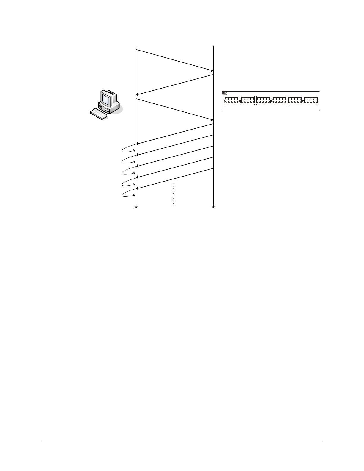
www.vtiinstruments.com
`
Host Computer
EX1629
5 7
0 2
3
HD
LAN
SHUNT
CAL
RES
SHUNT
CAL
RES
SHUNT
CAL
RES
1
4 6
13 15
8 10
11 9
12 14
21 23
16 18
19 17
20 22
29 31
24 26
27 25
28 30
37 39
32 34
35 33
36 38
45 47
40 42
43 41
44 46
PWR
EX1629
time time
Receive streaming data
Receive streaming data
Receive streaming data
Receive streaming data
Receive
:
vtex
1629
_
trig
_
init
()
response
Send
:
vtex
1629
_
enable
_
streaming
_
data
()
request
Receive
:
vtex
1629
_
enable
_
streaming
_
data
()
response
Send
:
vtex
1629
_
trig
_
init
()
request
User callback
User callback
User callback
User callback
User callback
FIGURE 6-3: STREAMING DATA WITH USER CALLBACK
The following sample code segment illustrates a very basic use of the streaming data interface.
The callback function, stream_callback, just prints the timestamps and data values to a FILE
handle. The FILE handle, as well as a sample count total variable, are stored in a user-defined data
structure. A pointer to this structure is passed to the vtex1629_enable_streaming_data function,
along with a function pointer to the streaming callback function. Later, when streaming data pages
(scans) are received, a pointer to the acquisition data, along with the pointer to the user-defined
data structure, are passed to the callback function. The user-defined data structure pointer is passed
as a void* and should be cast to the appropriate type within the callback function.
#define INSTR_LANGUAGE_SPECIFIC
#include<vtex1629.h>
typedef struct {
FILE *fout;
ViInt32 sample_count;
} user_struct;
user_struct my_struct = {0};
ViInt32 stream_callback( void *priv, EX1629_rpc_datapage *data )
{
user_struct *priv_struct; // pointer to user structure
ViInt32 ds_idx; // dataset index
ViInt32 smp_idx; // sample index
priv_struct = (user_struct *)priv;
/* Loop through all of the datasets in the datapage. */
for( ds_idx = 0; ds_idx < data->dataset.dataset_len && ds_idx <
MAX_NUM_DATASETS; ds_idx++ ) {
EX1629 Programming 89
Page 90

VTI Instruments Corp.
/* print the timestamp. */
fprintf( priv_struct->fout,
"Timestamp: %5u.%09u",
data->dataset.dataset_val[ds_idx]->timestamp_sec,
data->dataset.dataset_val[ds_idx]->timestamp_nsec);
/* print the data */
for( smp_idx = 0;
smp_idx < data->dataset.dataset_val[ds_idx]->data.data_len;
smp_idx++ ) {
fprintf( priv_struct->fout,
"\t%i %f\n",
data->dataset.dataset_val[ds_idx]->data.data_val[smp_idx]);
}
}
if( data->dataset.dataset_len > 0) {
priv_struct->sample_count++;
}
}
result = vtex1629_enable_streaming_data( vi,
&my_struct,
stream_callback );
result = vtex1629_trig_init( vi );
// application code…
result = vtex1629_abort( vi );
result = vtex1629_disable_streaming_data( vi );
It is imperative that the streaming data interface be enabled prior to initializing acquisition (the
vtex1629_trig_init function) and disabled after acquisition completes, or is aborted explicitly
(vtex1629_abort).
The streaming callback function extracts the acquisition and timestamp data from the
EX1629_rpc_datapage structure. Each datapage contains three data sets, which contains data for a
range of channels: the first data set contains data for channels 0 through 15, the second for 16
through 31, and the third contains data for channels 32 through 47. Only data for channels enabled
in the scanlist are included. That is, if the main input scanlist contains channels 0 through 15 and
16, the first data set (the zeroeth) will contain 16 samples (channels 0 through 15), the second data
set will contain 1 sample (channel 16), and the third data set will contain no samples.
Beyond the timestamp and acquisition values illustrated in the example above, the
EX1629_rpc_datapage structure also contains DIO sample data as well as data from the
Confidence Measurement Subsystem. The EX1629_rpc_datapage structure is documented in the
instrument driver header file.
Advanced Data Streaming Usage
In addition to the basic streaming data supported via the vtex1629_enable_streaming_data
function, the vtex1629_enable_streaming_dataEx function supports a more advanced streaming
interface. Where the vtex1629_enable_streaming_data automatically creates a thread, opens the
socket, configures the instrument for streaming data, etc., the vtex1629_enable_streaming_dataEx
only configures the instrument for streaming data, making the user application responsible for the
other tasks. This provides the application developer more control over the data streaming
mechanism than is allowed by the vtex1629_enable_streaming_data function. This, clearly, makes
90 EX1629 Programming
Page 91

use of the vtex1629_enable_streaming_dataEx function more complicated than the
vtex1629_enable_streaming_data function.
For most applications, the basic streaming data interface provides sufficient execution speed and
flexibility. If you believe your application would benefit from the advanced streaming interface,
please contact your application engineer for further details.
Calibration Data
Once calibration is run, a file with this data is stored in memory. To view this data, the following
code could be generated. This code determines the size of the calibration file first in order to
prevent overwriting any data that may already exist in the external memory location to which the
calibration file will be written. In this example, the self-calibration and full calibration files are
output in XML format.
Sample Code
ViStatus status = VI_SUCCESS;
ViChar errMessage[256];
ViInt32 fileType = 0;
ViInt32 bufferSize = 0;
ViString xmlBuffer_combined = 0;
ViInt32 actualSize = 0;
memset(errMessage, 0x00, sizeof(errMessage));
fileType = VTEX1629_CAL_DATA_COMBINED;
status = vtex1629_get_cal_file_size(instrumentHandle,
fileType,
&bufferSize);
if(status < VI_SUCCESS) {
<inform the user the API call failed>
}
if( (status >= VI_SUCCESS) && (bufferSize > 0) ) {
xmlBuffer_combined = malloc( bufferSize * sizeof( ViString ) );
status = vtex1629_get_cal_file(instrumentHandle,
fileType,
bufferSize,
xmlBuffer_combined,
&actualSize);
if(status < VI_SUCCESS) {
<inform the user the API call failed> }
...
free(xmlBuffer_combined);
}
www.vtiinstruments.com
EX1629 Programming 91
Page 92

VTI Instruments Corp.
STARTING/STOPPING ACQUISITION
Acquisition is started by using the vtex1629_trig_init function, which initializes the trigger
subsystem. This causes the trigger state machine to transition from the IDLE state to the Waiting
for ARM state (see Figure 4-1). Depending on the configuration of the Arm and Trigger sources,
data acquisition may begin immediately – if both Arm and Trigger are configured for Immediate
(VTEX1629_TRIG_SRC_IMMEDIATE) –, or at some point in the future when the instrument
receives the required signals (e.g., a raising edge on LXI 0). In general, after acquisition is
initiated by the vtex1629_trig_init function, it will continue until the requested number of samples
has been acquired, possibly several times, depending on the configuration of the Arm and Trigger
Count variables, and the value of Continuous Init.
status = vtex1629_trig_init( vi );
The acquisition may be halted at any time by using the vtex1629_abort function. This causes
acquisition to stop, and the trigger state machine transitions to the IDLE state (see Figure 4-1).
status = vtex1629_abort( vi );
92 EX1629 Programming
Page 93

www.vtiinstruments.com
SECTION 7
FUNCTION CALLS
INTRODUCTION
This section presents the instrument function set. It begins by listing the APIs according to
function and is then followed by an alphabetical listing. With each function is a brief description.
The remainder of this section is devoted to describing each function in detail. Each function entry
provides the function prototype, the use and range of parameters, and a description of the
function’s purpose.
FUNCTION RETURN VALUE
Each function will return a status that will contain either VI_SUCCESS or an error status returned
by the function call. Refer to the Error Messages section found later in the chapter for possible
error codes. If the vtex1629_error_message function call is used, it will return a description of the
error code returned by the last function call made.
FUNCTION TREE
The function set for the EX1629 has been categorized according to function and is presented
below.
Initialize
Initialize vtex1629_init
Limit Checking
Set Bridge Limit Enabled vtex1629_set_bridge_limit_enabled
Get Bridge Limit Enabled vtex1629_get_bridge_limit_enabled
Set Bridge Limit vtex1629_set_bridge_limit
Get Bridge Limit vtex1629_get_bridge_limit
Set Confidence Reporting Mode vtex1629_set_confidence_reporting_mode
Get Confidence Reporting Mode vtex1629_get_confidence_reporting_mode
Set Confidence Limit vtex1629_set_confidence_limit
Get Confidence Limit vtex1629_get_confidence_limit
Set LXI Limit Event vtex1629_set_lxi_limit_event_enabled
Get LXI Limit Event vtex1629_get_lxi_limit_event_enabled
Set LXI Limit Event Latch vtex1629_set_lxi_limit_event_latch
Get LXI Limit Event Latch vtex1629_get_lxi_limit_event_latch
Configuration Calls
Store Current Configuration vtex1629_store_current_config
Load Stored Configuration vtex1629_load_stored_config
Clear Stored Configuration vtex1629_clear_stored_config
Get Current Configuration Digest vtex1629_get_current_config_digest
Get Stored Configuration Digest vtex1629_get_stored_config_digest
Compare Digests vtex1629_compare_digests
EX1629 Command Set 93
Page 94

VTI Instruments Corp.
Lock Function Calls
Break Lock on Instrument vtex1629_break_lock
Check Lock on Instrument vtex1629_check_lock
Lock Instrument vtex1629_lock
Unlock Instrument vtex1629_unlock
Digital Input/Output Calls
Send Pulse vtex1629_send_dio_pulse
Configuration Read
Get Bank 0 Direction vtex1629_get_dio_bank0_direction
Get Bank 0 Pull-up vtex1629_get_dio_bank0_pullup
Get Bank 1 Direction vtex1629_get_dio_bank1_direction
Get Bank 1 Pull-up vtex1629_get_dio_bank1_pullup
Get Output State vtex1629_get_dio_output
Get Input State vtex1629_get_dio_input
Configuration Write
Set Bank 0 Direction vtex1629_get_dio_bank0_direction
Set Bank 0 Pull-up vtex1629_set_dio_bank0_pullup
Set Bank 1 Direction vtex1629_set_dio_bank1_direction
Set Bank 1 Pull-up vtex1629_set_dio_bank1_pullup
Set Output State vtex1629_set_dio_output
Event Control
Set DIO Configuration Events vtex1629_set_dio_config_events
Get DIO Configuration Events vtex1629_get_dio_config_events
Clear DIO Events vtex1629_dio_clear_event
Clear All DIO Events vtex1629_dio_clear_events_all
LXI Trigger Bus Calls
Send LXI Bus Pulse vtex1629_send_lxibus_pulse
Get LXI Bus Configuration vtex1629_get_lxibus_configuration
Get LXI Bus Output vtex1629_get_lxibus_output
Get LXI Bus Input vtex1629_get_lxibus_input
Set LXI Bus Configuration vtex1629_set_lxibus_configuration
Set LXI Bus Output vtex1629_set_lxibus_output
Scanlist Calls
Get Channel Scanlist vtex1629_get_scanlist
Set Channel Scanlist vtex1629_set_scanlist
Get Gain vtex1629_get_gain
Get Completion Resistor Value vtex1629_get_completion_resistor
Get Input Multiplexer vtex1629_get_input_multiplexer
Get Sampling Frequency vtex1629_get_sample_frequency
Get Confidence Scanlist vtex1629_get_conf_scanlist
Set Gain vtex1629_set_gain
Set Completion Resistor Mode vtex1629_set_completion_resistor
Set Input Multiplexer vtex1629_set_input_multiplexer
Set Sampling Frequency vtex1629_set_sample_frequency
Set Confidence Scanlist vtex1629_set_conf_scanlist
Trigger System Calls
Trigger Initiate vtex1629_trig_init
Software Arm vtex1629_soft_arm
Software Trigger vtex1629_soft_trig
Software Synchronize vtex1629_soft_synch
Reset vtex1629_reset_trigger_arm
Abort vtex1629_abort
Get Sample Count vtex1629_get_sample_count
Get Arm Source vtex1629_get_arm_source
94 EX1629 Command Set
Page 95

www.vtiinstruments.com
Get Arm Count vtex1629_get_arm_count
Get Arm Delay vtex1629_get_arm_delay
Get Trigger Source vtex1629_get_trigger_source
Get Trigger Count vtex1629_get_trigger_count
Get Trigger Delay vtex1629_get_trigger_delay
Get Trigger Timer vtex1629_get_trigger_timer
Get Synchronization Source vtex1629_get_synch_source
Get Sample Clock Source vtex1629_get_sample_clock_source
Get Arm Pattern Configuration vtex1629_get_pattern_arm_configuration
Get Trig Pattern Configuration vtex1629_get_pattern_trig_configuration
Set Sample Count vtex1629_set_sample_count
Set Arm Source vtex1629_set_arm_source
Set Arm Count vtex1629_set_arm_count
Set Arm Delay vtex1629_set_arm_delay
Set Trigger Source vtex1629_set_trigger_source
Set Trigger Count vtex1629_set_trigger_count
Set Trigger Delay vtex1629_set_trigger_delay
Set Trigger Timer vtex1629_set_trigger_timer
Set Synchronization Source vtex1629_set_synch_source
Set Sample Clock Source vtex1629_set_sample_clock_source
Set Arm Pattern Configuration vtex1629_set_pattern_arm_configuration
Set Trig Pattern Configuration vtex1629_set_pattern_trig_configuration
Set Trigger Source Timer vtex1629_set_trigger_source_timer
Filter Configuration Calls
Get IIR Filter Configuration vtex1629_get_IIR_filter_configuration
Set IIR Filter Configuration vtex1629_set_IIR_filter_configuration
Get Settling Time vtex1629_get_settling_time
Excitation Voltage Calls
Get Programmed Excitation Voltage vtex1629_get_excitation
Get Excitation Voltage Enabled vtex1629_get_excitation_enabled
Set Programmed Excitation Voltage vtex1629_set_excitation
Set Excitation Voltage Enabled vtex1629_set_excitation_enabled
EU Conversion Calls
Get EU Conversion Type vtex1629_get_EU_conversion
Get EU Conversion Excitation Voltage vtex1629_get_euconv_excitation
Get Unstrained Voltage vtex1629_get_unstrained_voltage
Get Gage Factor vtex1629_get_gauge_factor
Get Poisson Ratio vtex1629_get_poisson_ratio
Get Strain Units vtex1629_get_strain_units
Get Tare Value vtex1629_get_tare
Set EU Conversion Type vtex1629_set_EU_conversion
Set EU Conversion Excitation Voltage vtex1629_set_euconv_excitation
Set Unstrained Voltage vtex1629_set_unstrained_voltage
Set Gage Factor vtex1629_get_gauge_factor
Set Poisson Ratio vtex1629_set_poisson_ratio
Set Strain Units vtex1629_set_strain_units
Set Tare Values vtex1629_set_tare
Get Linear Scaling Coefficients vtex1629_get_linearscaling_configuration
Set Linear Scaling Coefficients vtex1629_set_linearscaling_configuration
Measure Unstrained Voltage vtex1629_measure_unstrained_voltage
Measure Excitation Voltage vtex1629_measure_excitation_voltage
Measure Confidence vtex1629_measure_confidence
Reset Tare Values vtex1629_reset_tare
Set Dynamic Excitation EU Enabled vtex1629_set_euconv_dynamic_excitation_enabled
Get Dynamic Excitation EU Enabled vtex1629_set_euconv_dynamic_excitation_enabled
EX1629 Command Set 95
Page 96

VTI Instruments Corp.
Shunt Configuration Calls
Get Shunt Source vtex1629_get_shunt_source
Get Shunt Enabled vtex1629_get_shunt_enabled
Get Shunt Value vtex1629_get_shunt_value
Set Shunt Source vtex1629_set_shunt_source
Set Shunt Enabled vtex1629_set_shunt_enabled
Set Shunt Value vtex1629_set_shunt_value
TEDS Calls
Get TEDS Data vtex1629_get_teds_data
Set TEDS Data vtex1629_set_teds_data
Erase TEDS Data vtex1629_erase_teds_data
Read TEDS MLAN vtex1629_read_teds_MLAN
Write TEDS MLAN vtex1629_write_teds_MLAN
Read TEDS URN vtex1629_read_teds_URN
Data Retrieval Calls
Get FIFO Count vtex1629_get_fifo_count
Read FIFO vtex1629_read_fifo
Read FIFO Extra vtex1629_read_fifoEx
Reset FIFO vtex1629_reset_fifo
Data Retrieval Calls - Advanced
Enable Streaming Data vtex1629_enable_streaming_data
Disable Streaming Data vtex1629_disable_streaming_data
Enable Streaming Data Expert Mode vtex1629_enable_streaming_dataEx
Self-Calibration Calls
Initialize Self-Calibration vtex1629_self_cal_init
Initialize Zero Calibration vtex1629_zero_cal
Query Self-Calibration File in Non-vol Memory vtex1629_self_cal_is_stored
Load Self-Calibration File from Non-vol Memory vtex1629_self_cal_load
Store Self-Calibration File to Non-vol Memory vtex1629_self_cal_store
Clear Self-Calibration File from Non-vol Memory vtex1629_self_cal_clear_stored
Clear Current Self-Calibration Image vtex1629_self_cal_clear
Get Self-Calibration Status vtex1629_self_cal_get_status
Get Self-Calibration Failure Status vtex1629_get_selfcal_status
Query Self-Calibration isRunning vtex1629_self_cal_is_running
Internal Calibration Source Calls
Get Calibration Source vtex1629_get_cal_source
Set Cal Source vtex1629_set_cal_source
Set Cal Out vtex1629_set_cal_out
Utility Function Calls
Reset vtex1629_reset
Self-Test Functions
Self-Test vtex1629_self_test
Self Test Init vtex1629_self_test_init
Self Test Get Status vtex1629_self_test_get_status
Error Message vtex1629_error_message
Error Query vtex1629_error_query
Revision Query vtex1629_revision_query
Instrument Discovery vtex1629_findinstr
Enable Logging vtex1629_enable_logging
Disable Logging vtex1629_disable_logging
96 EX1629 Command Set
Page 97

www.vtiinstruments.com
Get Serial Number vtex1629_get_instrument_serial_number
Get DSP Version vtex1629_get_dsp_version
Lead Wire Calls
Measure Lead Wire Resistance vtex1629_measure_lead_wire_resistance
Set Lead Wire Resistance vtex1629_set_lead_wire_resistance
Get Lead Wire Resistance vtex1629_get_lead_wire_resistance
Set Half-Bridge Lead Wire Desensitization vtex1629_set_half_bridge_lead_wire_desensitization
Get Half-Bridge Lead Wire Desensitization vtex1629_get_half_bridge_lead_wire_desensitization
Calibration File Query
Get Calibration File Size vtex1629_get_cal_file_size
Get Calibration File vtex1629_get_cal_file
Calibration Coefficient Query vtex1629_get_cal_coefficients
Close
Close vtex1629_close
EX1629 Command Set 97
Page 98

VTI Instruments Corp.
Command
Description
vtex1629_abort
Aborts data acquisition.
vtex1629_allow_all_channels
Allows the user to include channels that failed
calibration in the scanlist for data acquisition.
vtex1629_break_lock
Releases a lock on the instrument.
vtex1629_check_lock
Queries the lock status of the instrument.
vtex1629_clear_stored_config
Erases the stored configuration from nonvolatile
storage.
vtex1629_close
Closes an instrument programming session.
vtex1629_compare_digests
Compares the two provided digests byte-bybyte.
vtex1629_dio_clear_event
Clears the DIO event configuration for the
specified inputLine.
vtex1629_dio_clear_events_all
Clears the DIO event configuration for all
events.
vtex1629_disable_logging
Stops the logging of driver calls.
vtex1629_disable_streaming_data
Stops streaming data from instrument.
vtex1629_enable_logging
Allows an application to log messages to a file
for later review.
vtex1629_enable_streaming_data
Starts data streaming from instrument.
vtex1629_enable_streaming_dataEx
Start data streaming from instrument (expert
mode).
vtex1629_erase_teds_data
Erases the data on a TEDS device for one
particular channel.
vtex1629_error_message
Outputs the error message associated with the
statusCode parameter.
vtex1629_findinstr
Scans the LAN for available EX1629
instruments.
vtex1629_get_arm_count
Queries and returns the arm count for the
EX1629.
vtex1629_get_arm_delay
Queries and returns the arm delay for the
EX1629.
vtex1629_get_arm_source
Queries and returns the current setting for the
arm source.
vtex1629_get_bridge_limit
Queries and returns the minimum and maximum
bridge limit values.
vtex1629_get_bridge_limit_enabled
Queries and returns the enabled status of the
bridge limit function.
vtex1629_get_cal_coefficients
Queries and returns the value of a selected
calibration coefficient for one or more channels.
vtex1629_get_cal_file
Reads up to bufferSize characters from the
EX1629 and places them in the XML buffer.
vtex1629_get_cal_file_size
Returns the total buffer size required to read the
cal data.
vtex1629_get_cal_source
Queries and returns the current setting for the
calibration input source.
vtex1629_get_completion_resistor
Queries and returns the mode and the value of
the completion resistor for a specific channel.
vtex1629_get_conf_scanlist
Queries and returns a list of confidence data
values that are currently configured to be
measured and stored with data acquisition.
vtex1629_get_confidence_limit
Queries and retrieves the current confidence
limit settings.
ALPHABETICAL FUNCTION SET
The following table provides a summary of the function calls used by the EX1629 along with an
abbreviated description of the function. The pages following this table are function definitions that
provide in-depth detail for each function. A sample function definition is provided immediately
following this table to illustrate what each section of the definition describes.
98 EX1629 Command Set
Page 99

www.vtiinstruments.com
Command
Description
vtex1629_get_confidence_reporting_mode
Queries and retrieves the reporting mode for
confidence limit checking.
vtex1629_get_current_config_digest
Retrieves the digest for the current instrument
configuration.
vtex1629_get_dio_bank0_direction
Indicates whether bank zero of the digital I/O is
configured as input or output.
vtex1629_get_dio_bank0_pullup
Queries and returns the pull-up mode for bank
zero of the digital I/O.
vtex1629_get_dio_bank1_direction
Indicates whether bank one of the digital I/O is
configured as input or output.
vtex1629_get_dio_bank1_pullup
Queries and returns the pull-up mode for bank
one of the digital I/O.
vtex1629_get_dio_config_events
Queries and returns the current setting for DIO
event transitions.
vtex1629_get_dio_input
Queries and returns the current input state of
both banks of the digital I/O.
vtex1629_get_dio_output
Queries and returns the current programmed
output state of both banks of the digital I/O.
vtex1629_get_dsp_version
Returns the DSP version information for a given
analog board.
vtex1629_get_EU_conversion
Reads the EU conversion type for a specific
channel.
vtex1629_get_euconv_dynamic_excitation_enabled
Queries and returns the dynamic excitation EU
conversion state
vtex1629_get_euconv_excitation
Queries and returns the current value used in
EU conversions for the excitation voltage for a
given channel.
vtex1629_get_excitation
Queries and returns the programmed excitation
voltage for a given channel.
vtex1629_get_excitation_enabled
Queries and returns the enabled status of the
excitation voltage for a specific channel.
vtex1629_get_fifo_count
Queries the EX1629 for the current FIFO page
count.
vtex1629_get_gain
Reads the specified channel's current signal
conditioning gain.
vtex1629_get_gauge_factor
Queries and returns the gage factor for a
specific channel. This is one of the parameters
used in EU conversion calculations.
vtex1629_get_half_bridge_lead_wire_desensitization
Queries and returns the lead wire desensitization
factor for the specified channel.
vtex1629_get_IIR_filter_configuration
Queries and returns the IIR filter configuration
parameters for a given channel.
vtex1629_get_input_multiplexer
Queries and returns the input multiplexer
source.
vtex1629_get_instrument_serial_number
Returns the instrument's serial number
vtex1629_get_lead_wire_resistance
Queries and returns the currently defined lead
wire resistance value.
vtex1629_get_linearscaling_configuration
Returns the slope (m) and intercept (b)
parameters for a given channel.
vtex1629_get_lxi_limit_event_enabled
Returns which measurement channels are
enabled for Limit Events on the specified LXI
Trigger Bus line.
vtex1629_get_lxi_limit_event_latch
Returns a mask indicating which LXI trigger
lines will be latched for LXI Limit Event
outputs.
vtex1629_get_lxibus_configuration
Queries and returns information pertaining to a
specified LXI Trigger Bus channel.
vtex1629_get_lxibus_input
Queries and returns the input state of each of the
channels on the LXI Trigger Bus.
EX1629 Command Set 99
Page 100

VTI Instruments Corp.
Command
Description
vtex1629_get_lxibus_output
Queries and returns the output state of each of
the channels on the LXI Trigger Bus.
vtex1629_get_pattern_arm_configuration
Queries and returns the EX1629’s current
configuration for the pattern arm mode of
operation.
vtex1629_get_pattern_trig_configuration
This queries and returns the EX1629’s current
configuration for the pattern trigger mode of
operation.
vtex1629_get_poisson_ratio
Queries and returns the Poisson ratio for a
specific channel. This is one of the parameters
used in EU conversion calculations.
vtex1629_get_sample_clock_source
Queries and returns the configured sample clock
source.
vtex1629_get_sample_count
Queries and returns both the pre- and posttrigger sample counts for the EX1629.
vtex1629_get_sample_frequency
Queries and returns the currently configured
sampling frequency for all channels on the
EX1629.
vtex1629_get_scanlist
Queries and returns a list of channels currently
configured to be sampled in the data acquisition
process.
vtex1629_get_selfcal_status
Queries and returns self-calibration failure
status for the selected channels
vtex1629_get_settling_time
Queries and returns the current settling time for
a particular channel.
vtex1629_get_shunt_enabled
Queries and returns the enabled status of a
particular channel's shunt resistor.
vtex1629_get_shunt_source
Queries and returns the shunt source for a
particular channel.
vtex1629_get_shunt_value
Queries and returns a shunt resistor value based
on a given channel and shunt source.
vtex1629_get_stored_config_digest
Retrieves the digest of the instrument
configuration saved in non-volatile memory.
vtex1629_get_strain_units
Queries and returns the configured strain units
for a given channel.
vtex1629_get_synch_source
Queries and returns the synchronization source.
vtex1629_get_tare
Reads the currently configured tare value for a
specific channel
vtex1629_get_teds_data
Returns the TEDS data for a given channel.
vtex1629_get_trigger_count
Queries and returns the currently configured
trigger count for the EX1629.
vtex1629_get_trigger_delay
Queries and returns the trigger delay for the
EX1629.
vtex1629_get_trigger_source
Queries and returns the current setting for the
trigger source.
vtex1629_get_trigger_timer
Queries and returns the trigger system timer for
the EX1629.
vtex1629_get_unstrained_voltage
Queries and returns the unstrained voltage
currently configured for a given channel.
vtex1629_identify_sensor
Controls the activity of a sensor-linked LED.
vtex1629_init
Opens a session with the instrument and returns
a session handle.
vtex1629_load_stored_config
Applies the stored configuration to the
instrument.
vtex1629_lock
Attempts to acquire a lock on the instrument.
vtex1629_measure_confidence
Measures the indicated bridge parameter to
indicate measurement confidence.
vtex1629_measure_excitation_voltage
Measures the total excitation voltage for a list of
channels.
100 EX1629 Command Set
 Loading...