

Page 1

MB and FD Series
Unitized Distribution Substation
Installation/Operation Guide
.
Revision Level 3.00
October 2000
VTI, Incorporated
24 McMillan Way
Newark, DE 19713
Phone (302) 738-0500
FAX (302) 738-6594
Manual No. 90002970
Page 2

To insure proper installation, this manual must be read prior to starting the
installation process.
1. Introduction
This manual covers installation instructions for the MB Series and FD Series of Unitized
Distribution substations (UDS).
The MB Series UDSs are implemented with a circuit breaker on the secondary of the
transformer and an optional circuit breaker on the primary of the transformer.
The FD Series UDSs are implemented with a fused disconnect switch on the secondary of
the transformer and an optional fused disconnect switch on the primary of the transformer.
1.1 Reference Drawings (either standard drawings listed below or custom drawings for
specific projects are included with each MB Series/FD Series UDS)
Refer to the MAIN ASSEMBLY AND WIRING DIAGRAM which have been
specifically prepared for your order. These drawings provide the overall cabinet
dimensions, mounting information, component location, wiring, branch circuit
breaker type and rating, plus a bill of material listing manufacturer and rating of all
major components.
2. INITIAL CONSIDERATIONS
Move the UDS Cabinet to the desired location and remove the shipping crate from the
cabinet.
Remove the field wiring entry plate on top of the cabinet to obtain access to wireways.
Turn the secondary disconnect switch (breaker) to the “OFF” position.
Loosen the fasteners which secure the door to the 42 circuit breakers and open the door.
Place all the circuit breakers in the “OFF” position. Remove the five screws holding down
the trim panel covering the 42 circuit breakers. Remove the trim panel to obtain access to
the circuit breaker terminal blocks.
Remove the transformer cover plate.
If the optional primary disconnect switch (breaker) is installed, turn it to the “OFF”
position, loosen the fasteners which secure the primary disconnect door and open the
door.
Page 3

3. CABINET WIRING
3.1 Load WIRING
Ensure that each load wire pair from the field is electrically disconnected from all power
sources prior to handling. Pull the wire pair from each load to the UDS cabinet and route
through the field wiring entry in the top of the cabinet to the circuit breaker compartment.
Cut and strip the wire pair for termination on the appropriate circuit breaker and the
neutral bus located at the bottom of the circuit breaker compartment.
Prior to connecting the wire pair to the circuit breaker, verify the integrity of the wire
insulation by Hy-potting each conductor to ground with voltage set for (2 x rated voltage
+ 1000V). If successful, connect each wire pair to the circuit breaker and/or neutral bus.
After all wire pairs have been connected, replace the trim panel that covered the circuit
breakers, close the circuit breaker door and tighten the fasteners which secure the door.
3.2 FEEDER WIRING
WARNING:
MAKE SURE THAT THE THREE PHASE 400/415 & 480/600 VOLT, 50/60 HZ,
CIRCUIT BREAKER OR DISCONNECT SWITCH WHICH WILL FEED
POWER TO THE CABINET IS DE-ENERGIZED AND LOCKED OUT BEFORE
ATTEMPTING TO PULL THE FEEDER CABLE TO THE UDS CABINET!
Based on the transformer rating of the UDS cabinet, pull appropriately sized four
conductor cable from the main disconnect switch or circuit breaker through the input
power conduit at the top of the cabinet.
Page 4
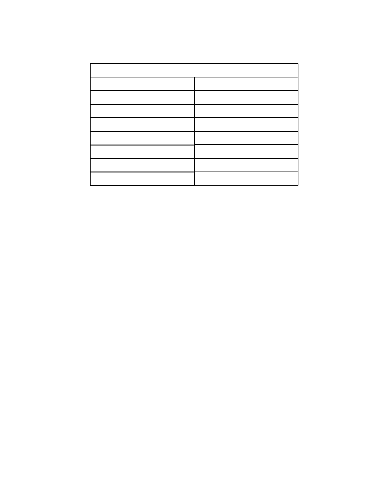
The minimum size wire is listed in the table below:
Cable Size
400/415V transformer rating
Minimum wire size AWG
30 KVA 8 AWG
45 KVA 6 AWG
75 KVA
480v transformer rating
30 KVA
45 KVA
75 KVA
Minimum wire size AWG
2 AWG
8 AWG
6 AWG
2 AWG
Verify the feeder insulation by Hy-potting each feeder between phase and ground with
voltage set to (2 x rated voltage + 1000V), e.g., 2000 VAC for 400/415 & 480V rating,
and 2500 VAC for 600V rating. If the Hy-pot test is successful, proceed to connect the
ground wire in the feeder cable to the ground lug at the feeder supply point. Now proceed
to connect each of the three phase conductors in the feeder cable circuit breaker or
disconnect switch in the feeder supply point.
Close the transformer compartment door. Also close the optional primary disconnect
switch door if applicable.
Ensure that the primary and secondary disconnect switches and the 42 circuit breakers on
the UDS cabinet are all in the “OFF” position.
This completes the installation of the Unitized Distribution Substation.
4. Operation
Provide power to the UDS by closing the disconnect switch on the circuit breaker feeding
the UDS.
If supplied as an option, place the primary disconnect switch or the primary circuit breaker
to the “ON” position.
Place the secondary disconnect switch or breaker to the “ON” position.
Place the individual circuit breaker to the “ON” position, as desired.
Page 5
Verify that the total load connected to the UDS does not exceed the rating of the
transformer supplied, i.e., 30 KVA, 45 KVA or 75 KVA.
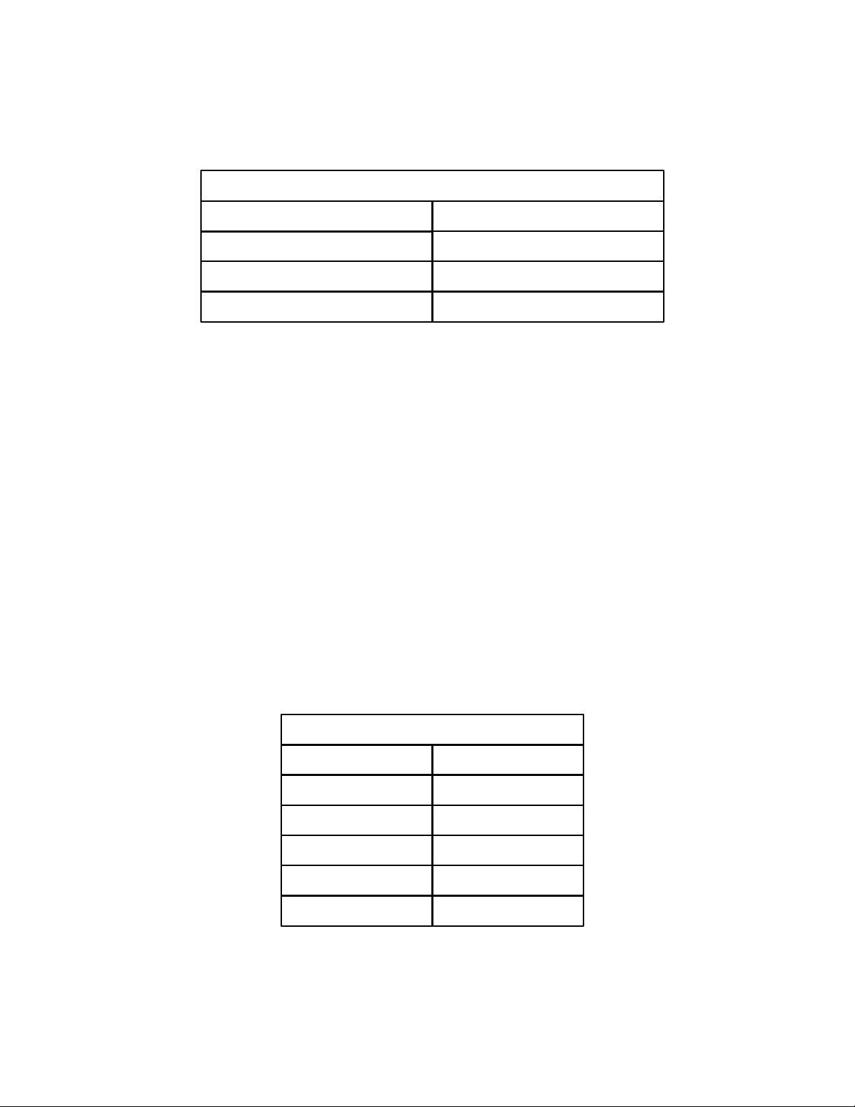
Cable Size
600V transformer rating
Minimum wire size AWG
30 KVA 10 AWG
45 KVA 6 AWG
75 KVA 2 AWG
If the optional primary disconnect switch is installed, terminate the feeder wiring at the
primary disconnect switch. Connect the three phase conductors in the cable (black, red
and blue) to the disconnect terminals identified as “L1”, “L2”, and “L3”, respectively.
Connect the ground conductor (green) to the ground lug provided in the primary
disconnect compartment of the cabinet. Make sure that these terminations are secure.
If the optional primary disconnect switch is not installed, terminate the feeder wiring at the
transformer located in the compartment at the bottom of the UDS cabinet. Connect the
three phase conductors in the cable (brown, orange and yellow) to the transformer primary
terminals identified as “H1”, “H2”, and “H3”, respectively. Connect the ground
conductor (green) to the ground lug provided in the transformer compartment of the
cabinet. Make sure that these terminations are secure.
Measure the phase to phase voltage of the power source that will feed the UDS cabinet.
Referring to the tap chart on the transformer, connect the numbered taps on each coil
which correspond most closely with the measured source voltage as shown in the table
below.
400/415 volt transformer tap chart
Line voltage Tap number
435 1
425 2
415 3
404
4
394 5
Page 6
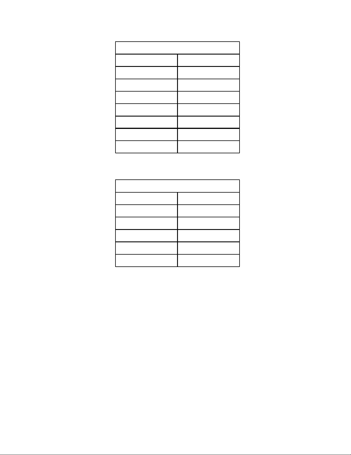
480 volt transformer tap chart
Line voltage Tap number
504 1
492 2
480 3
468 4
456 5
444 6
432 7
600 volt transformer tap chart
Line voltage Tap number
600 1
585 2
570 3
555 4
540 5
 Loading...