

Page 1
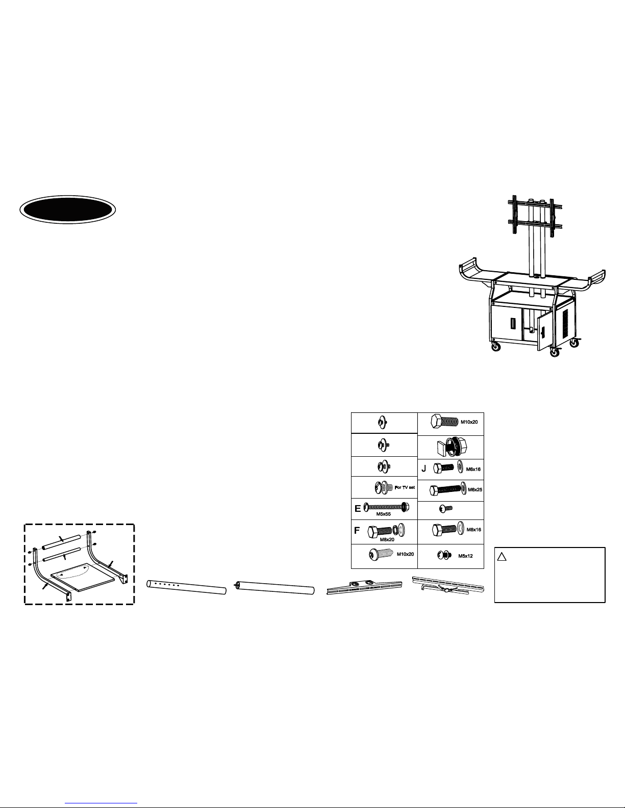
Note: This unit is easier to assemble with two people.
Tools required
Hex wrench
L key
Adjustable wrench/pliers
Rubber mallet
WARNING:Please keep
the TV mounting screws
M5, M6, M8, M10 and the L
key in a secure location as
they may be required for
use with the flat panel TV
at a later time.
Page 1
( Instructions continued on next page )
Model:10400
Screw table
Some screws may have already
screwed on the related parts.
N
M
(On the upper horizontal mount)
I
H
L
G
K
For TV set
M5x10
M5x12
M6x12
M8x16
M10x16
For TV set
For TV set
(On the lower horizontal mount)
(On the handle rail)
(On the lower pole)
(On the handle bar & handle support bar)
(On the legs)
PROP 65 WARNING: This product
contains the chemical known to the
State of California to cause cancer
and birth defects or other reproductive
harm.
!
Instruction sheet --
VTI
Flat panel TV cart with cabinet
Model number: 10400
Congratulations for having chosen this excellent VTI product.
To assure your complete satisfaction, this product is warranted against defect in manufacture for one year after the
purchase date. Any parts requiring replacement during the 1--year period, under normal use and service, as a result
of defective workmanship, will be replaced by VTI or by an authorized VTI dealer, without cost, except for transportation
charges. All unit should be returnd in original packing to guarantee safe transport. VTI is not responsible for damage in
shipment.
If you have any questions regarding the assembly of your table, please call the VTI helpline at (626)333-6638.
Manufacturing, Inc.
VTI
Parts list
Qty. Description
1 Top shelf with decal
1 Middle shelf
1 Bottom shelf
2 Side panel for cabinet
1 Rear panel for cabinet
1 Left door assembly
1 Right door assembly
2 Leg (Labeled "X")
2 Leg (Labeled "O")
2 L-Handle rail
2 R-Handle rail
2 Handle shelf
2 Handle bar
Qty. Description
2 Handle support bar
2 Upper pole
2 Lower pole
2 Horizontal mount
2 Vertical mount
2 Caster with brake
2 Caster without brake
1 Power cord
1 Electrical bracket
3 Set Screw and serrated nut (E)
25
Set Square head bolt, washer and hex nut (I)
8 Set Hex head screw & washer for fixing handle shelf (J)
2 Security screw for upper horizontal mount (G)
2 Screw for lower horizontal mount (H)
2 Set Screw for fixing the support pole (M)
12 Set Hex head screw & washer for the caster (F)
8 Set Hex head screw & washer for the handle (K)
8 Philip head screw for the handles shelf (L)
25 Set Philip head screw for the door & side panel (N)
L-H
an
d
l
e
rai
l
Handle
bar
Handle support bar
Handle shelf section assembly part
Shelf
R-Handle rail
Horizontal mount
Lower pole
Upper pole
Vertical mount
Page 2
Page 2
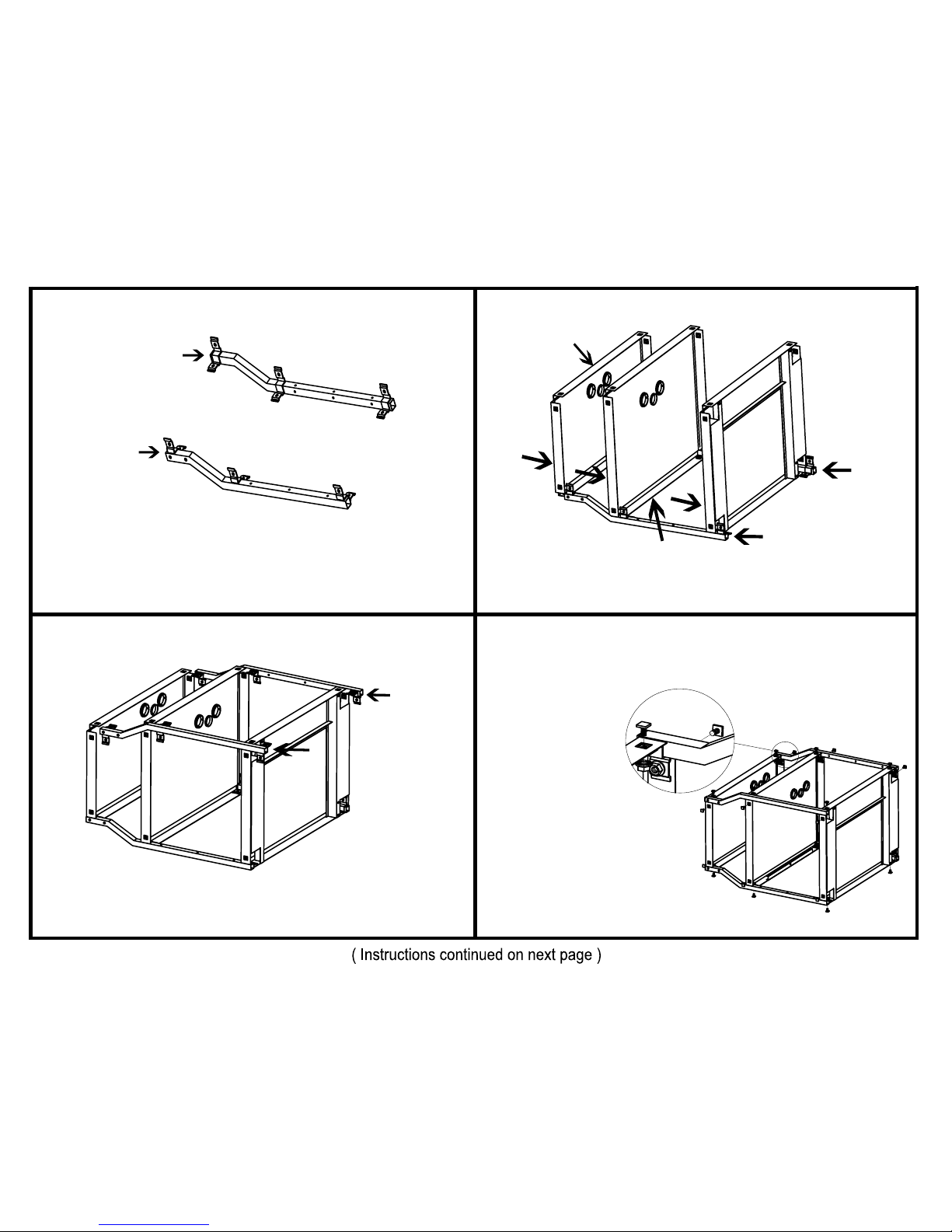
1.
Lay front legs (labeled "O" and "X") on the floor with the brackets
facing upward and inward as illustrated. Note: legs,when placed
on the floor should bend upward, off the floor at their top end and
the width of the unit should remain constant all the way to the top.
T
op
Bottom
Leg"O"
Leg"X"
2.
Slide each shelf over the brackets of the legs. The larger and without
holes shelf is the bottom. The top shelf has the VTI decal on it.
3.
Slide the two remaining legs onto the shelves as illustrated. Make
sure that the brackets are inside the shelves.
4.
HAND TIGHTEN
the top, middle and
bottom shelves at
the two corners with
square head bolt,
washer and nut
(screw table I) as
illustrated. Please
make sure washer
and nut are together
on the inside of the
leg bracket.
Leg "X"
Leg "O"
Top
Middle
Bottom
Back of shelf
Front of shelf
Leg"O"
Leg"X"
Page 3
Page 3
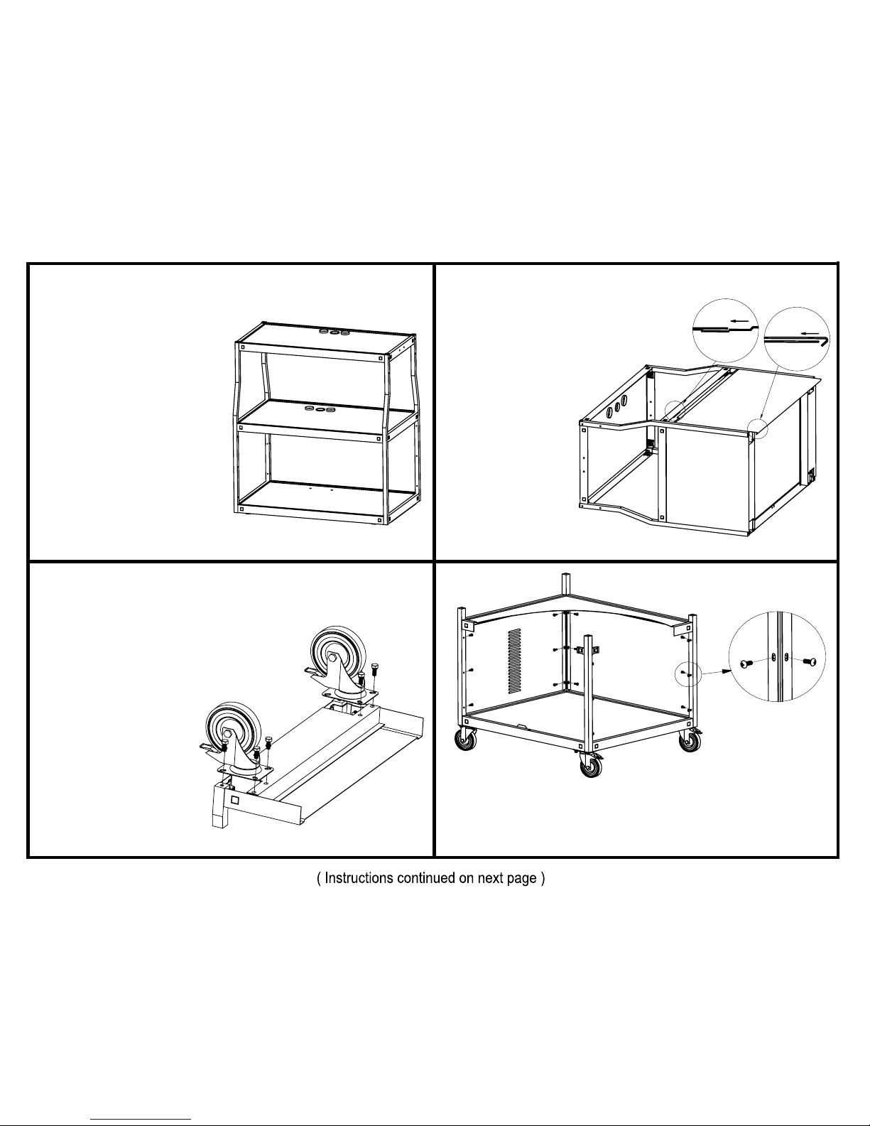
5.
In order to have the unit properly
aligned, stand unit upright on a
level surface. Gently rock unit
back and forth to realign and
level the unit.TIGHTEN ALL
NUTS AND BOLTS WITH
WRENCHES AT THIS TIME.
Unit should now be properly
aligned and level. If unit is not
level at this time, repeat the
above steps before proceeding
to step 6.
7.
Lay unit on the floor. Align the holes on the
caster with the holes on the corner of the
bottom shelf. Use the hex screws
(see Screw table F) and tighten
the caster. Repeat the same
for the other three casters.
It is recommended you
place the locking casters
on either the right side
or left side of the unit
for safer and easier
movement of cart
through doorways, ect..
6.
Slide the back panel between the
middle and bottom shelf. The
bottom of the back panel
needs to hook onto the
bottom frame lip and
the top of the panel
needs to go in
between middle shelf
lip and the brackets.
The side panels
Assembly as same
as above steps.
8.
To secure the cabinet panel, use the machine screws (see screw
table N) to tighten the cabinet panels to the frame poles as shown.
There are three screws on each side.
Page 4
Page 4
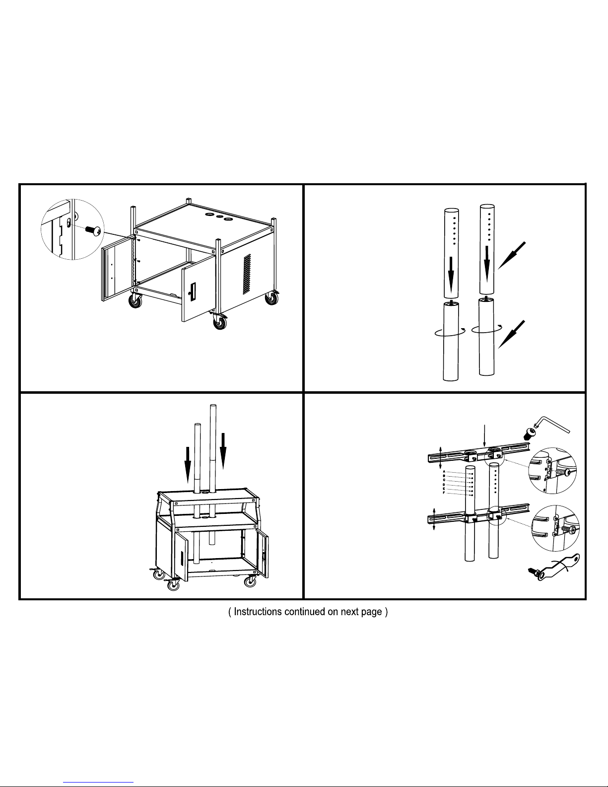
10.
Hand-tighten the upper
pole (with holes) to the
lower poles.
Upper pole
Lower pole
9.
Install the two doors onto the frame with three machine screws
(see screw table N) on each side. Do not tighten completely
at this time. Adjust the doors to make sure they close and lock
OK. Tighten all screws.
11.
Insert the two supporting
poles onto the holes of top
and middle shelves as
shown.
12.
Insert the two horizontal
mounts onto the supporting
poles. Note: The mount with
adjustable screw(see screw
table H) should go on the
bottom. Screw(see screw
table G) the top mount to
desired height from A to F.
Adjust the bottom mount
height according to the TV
screw position as shown.
T
op horizontal mount
Bottom horizontal mount
Page 5
Page 5
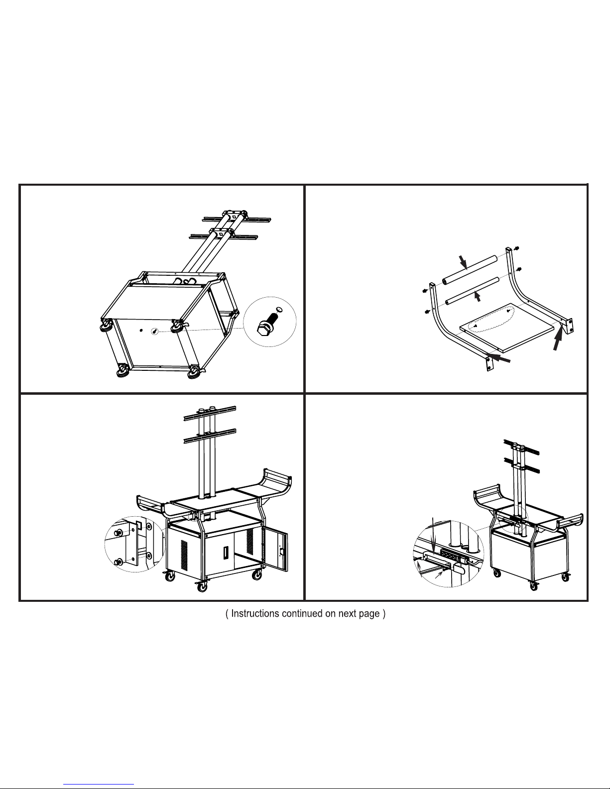
16.
Electrical bracket assembly instruction
A. Push power cord into
cord winder bracket.
B. Attach electrical bracket
to back side of top
shelf with two nuts
and bolts(see screw
table E). Tighten
nuts and bolts
securely. Wrap
power cord
around wings
of the bracket.
Bolts
15.
Unscrew the screws from
the legs (see screw table J).
Align the holes on the
bracket of the handle shelf
with the holes on the
cart, tighten the screws.
L-Handle Rail
Handle support bar
Handle bar
Shelf
R-Handle Rail
13.
Tighten the two
supporting poles
onto the bottom
shelf with two
screws as shown
(see screw
table M).
Electrical
bracket
14.
Handle shelf section assembly
Unscrew the screws from
handle bar, handle support
bar and handle rail (see
screw table K & L). Align
the holes on the handle
bar with the holes of the
handle rail, the holes on
the handle support bar
with the holes of handle
rail, the holes on the shelf
with the holes of the handle
rail, tighten the screws as
shown.
Page 6
If any parts or hardware are missing or damaged, Do Not
Return the unit to your dealer. Call the VTI helpline at
(626)333-6638 for immediate parts replacement.
15046 Proctor Avenue,
City of Industry, CA 91746, USA
Tel.:(626)333-6638; Fax:(626)333-6631.
Manufacturing, Inc.
VTI
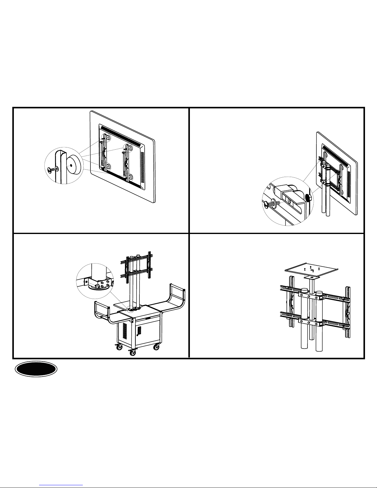
20.
Assembly Web. Cam. platform instruction (Optional part)
19.
Laptop shelf assembly (Optional part)
To install the laptop
shelf, wrap the
bracket around the
TV mount pole and
fasten the screws
as shown.
17.
Use the appropriate screws needed (M5, M6, M8 or M10, see
screw table M5x12,M6x12,M8x16 or M10x16) to fasten the flat
panel TV onto the vertical mounts as shown.
18.
Hook the vertical mount onto the top
horizontal mount. Align the vertical
mount with the top horizontal mount,
fasten the vertical mount onto the
horizontal mount as shown. Align
the bottom horizontal mount
with the vertical mount,
fasten the horizontal
mount onto the poles.
Use the screw to fasten
the vertical mount to the
bottom horizontal mount
as shown.
Page 6
To install the Web. Cam.
platform, insert the
platform support on the
middle hole between the
two TV mounting poles.
Align the platform with
the holes on the support
and fasten the screws.
 Loading...