

VTI 10235 Instruction Sheet
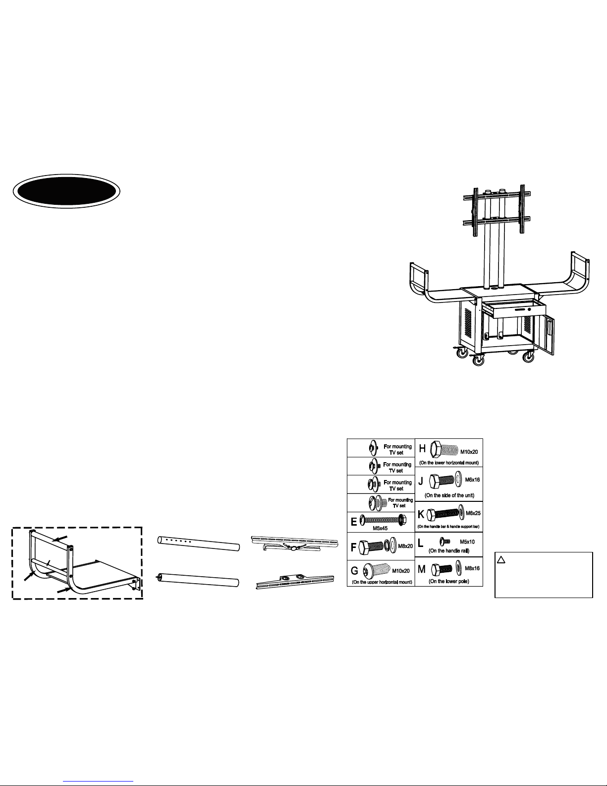
Parts list
Qty. Description
1 Body of cart
2 Handle shelf
2 L-Handle rail
2 R-Handle rail
2 Handle bar
2 Handle support bar
2 Upper pole
2 Lower pole
2 Horizontal mount
2 Vertical mount
Qty. Description
2 Caster with brake
2 Caster without brake
1 Electrical bracket
1 Power cord
3 Set Screw and serrated nut (E)
2 Set Hex head screw & washer for the pole (M)
2 Screw for upper horizontal mount (G)
2 Screw for lower horizontal mount (H)
8 Set Screw for fix the handle shelf on the body of cart (J)
16 Set Hex head screw & washer for the caster (F)
8 Set Hex head screw & washer for the handle (K)
8 Phillips head bolt for fix handle shelf (L)
Instruction sheet -- VTI Flat panel TV cart
Model number: 10235
Congratulations for having chosen this excellent VTI product.
To assure your complete satisfaction, this product is warranted against defect in manufacture for one
year after the purchase date. Any parts requiring replacement during the 1--year period, under normal
use and service, as a result of defective workmanship, will be replaced by VTI or by an authorized
VTI dealer, without cost, except for transportation charges. All unit should be returnd in original packing
to guarantee safe transport. VTI is not responsible for damage in shipment.
If you have any questions
regarding the assembly of your table, please call the VTI helpline at (626)333-6638.
Note: This unit is easier to assemble with two people.
Manufacturing, Inc.
VTI
Tools required
Hex wrench
L key
Adjustable wrench/pliers
Rubber mallet
WARNING:Please keep
the TV mounting screws
M5, M6, M8, M10 and the
L key in a secure location
as they may be required
for use with the flat panel
TV at a later time.
PROP 65 WARNING: This product
contains the chemical known to the
State of California to cause cancer
and birth defects or other reproductive
harm.
!
Screw table
Some screws may have already
screwed on the related parts.
M5x12
M6x12
M8x16
M10x16
Model: 10235
Horizontal mount
Lower pole
Upper pole
( Instructions continued on next page )
Page 1
Handle shelf section assembly parts
L-Handle rail
Handle bar
Ha
ndle
sup
port
bar
Handl
e
she
l
f
R-Handle rail
Vertical mount
Page 2
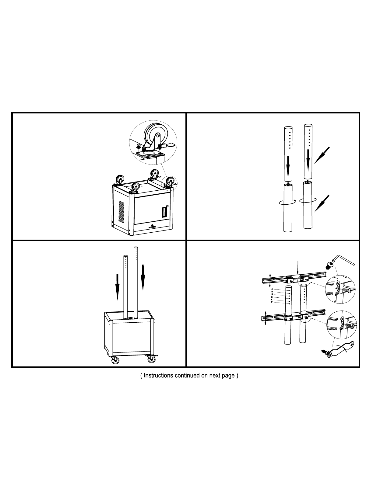
1.
Lay unit on floor . Align
the holes on the casters
with the holes on the
corner of the bottom
shelf. Use the hex screws
(see screw table F) and
tighten the caster. Repeat
the same for the other three
casters. It is recommended
you place the locking casters
on either the right side or left
side of the unit for safer and
easier movement of cart
through doorways, ect..
4.
Insert the two horizontal
mounts onto the
supporting poles. Note:
The mount with adjustable
screw(see screw table H)
should go on the bottom.
Screw(see screw table G)
the top mount to desired
height from A to F. Adjust
the bottom mount height
according to the TV screw
position later.
T
op h
or
iz
ontal mo
unt
Bottom horizontal mount
2.
Hand-tighten the upper
pole (with holes) to the
lower poles.
Upper pole
Lower pole
3.
Insert the two TV supporting
poles onto the holes on
top shelf.
Back view
 Loading...