

Page 1
C5-DJ4S
User Manual
Audio Phone
Please read this manual carefully before using the product you purchase, and keep
it well for future use.We reserve the right to modify the specication in this manual at
any time without notice.
Page 2
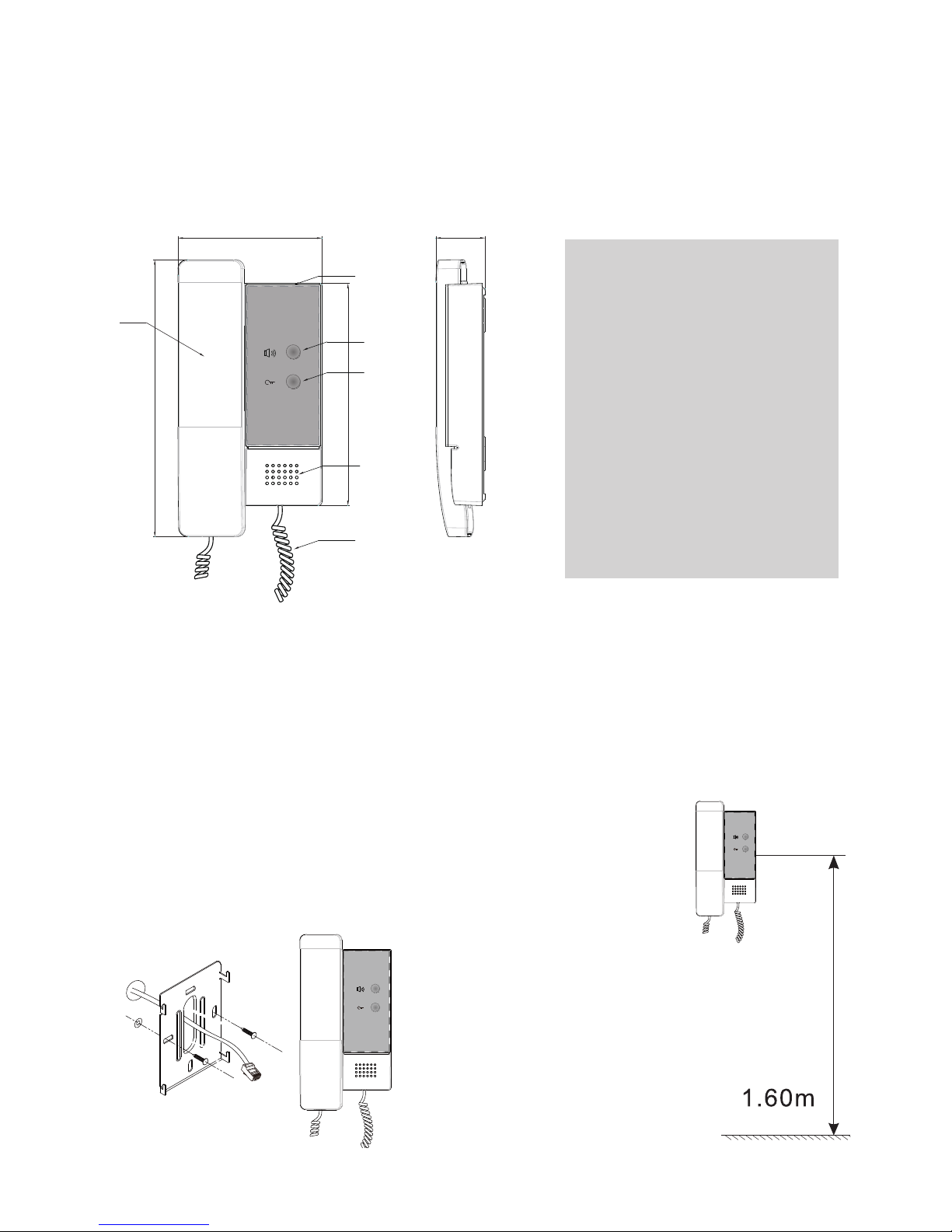
1.Parts and Functions
2. Unit Mounting
187
33.2
150
97.1
1
2
3
4
5
Side View
6
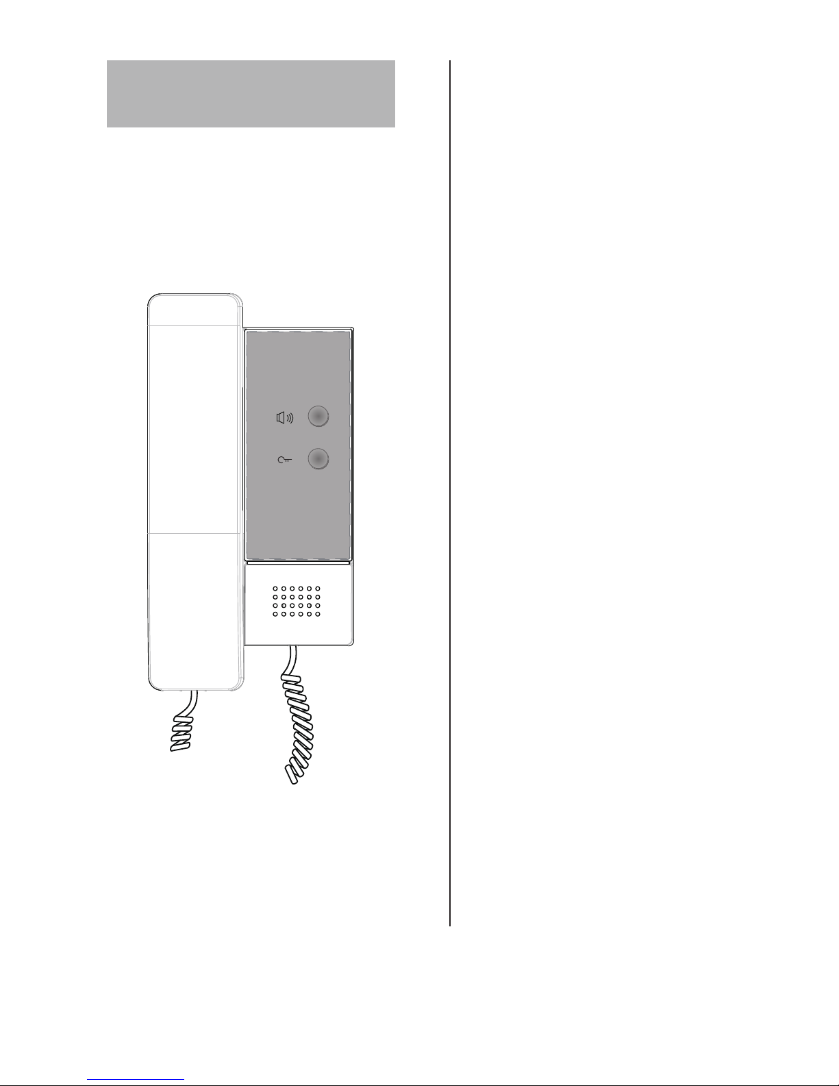
1. Handset
2. Call Button
3. Unlock Button
4. Speaker
5. Handset line
6. Unit Base
1. Fix 2 screws to the wall at a appropriate height
2. Connect the system correctly
3. Attach the audio phone to the bracket.
Page 3

3. Basic Operations
4. C5-DJ4S Address Conguration
Door Release Function:
When visitor calls from outdoor,the audio phone rings, pick
up handset to talk with the visitor,then press UNLOCK button to open the door for
visitor.
Call Guard Unit Center:
Pick up handset, then press CALL button to call guard
unit center directly, if the Guard person answers the call, talking with the Guard person
is activating.
Alarm to Guard Unit:
When the audio phone is in standby mode, press CALL
button to alarm to the Guard Unit directly.
Every C5-DJ4S handset must have a unique address(room code) for the door station to
identify. See the following steps to set the address:
1. Connect the system correctly and power on for the system(including the door station
and the Audio handset)
2. When door station is in standby, Press # 8003 on the door station, then input the
password(default is 66666666), the Monitor Program page will be shown:
3. Press
CALL
Button on C5-DJ4S, the previous room code will be shown on the
'Old M.Code' eld.
4. Input the new 4 digit room code on the door station, then press the # key to conrm, a
'Updated' massage will show if program successfully.
Note:the example is using MR6L door station for reference.
V id e o E n t ry S ys t e m
- -- -- -- -- -- -- - -- -- -- -- - -- --
[ 3] Mo n i t o r Pr og ra m
- -- -- -- -- -- -- - -- -- -- -- - -- --
o f t h e M on i t or
1 . Pr es s t h e C al l B u t t on
P ro gr a mm i n g St e ps :
Ne w M. Co d e [ - - - - ]
Ol d M . Co d e [ - - - - ]
W i t h i n 1 0 S ec on ds
2 . I n pu t n e w C od e
3 . Pr es s # t o pr og ra m
V id e o E n t ry S ys t e m
2 0- 0 8
0 6: 1 8
S ys t e m R ea dy
V id e o E n t ry S ys t e m
2 0 -0 8
0 6: 1 8
S ys t e m R ea dy
[ 8 0 0 3 ]
1 2 3
4 5 6
7 8
# 0 *
9
Page 4

5.Specication
●Power supply: DC 24V
●Power consumption: Standby 4W; Working status 10W
●Video signal: 1Vp-p, 75Ω, CCIR standard
●Wiring: CAT-5 cable
●Dimension: 187(H)X97(W)X33(D)mm
C5-ENG-DJ4S-V1
 Loading...