

Page 1

Analog Contemporary Corded 1-line Hotel Phone User Guide
A2210-NS
Before using this telephone, please read Important safety instructions on page 7.
Parts checklist
Items contained in the product package:
Model name Model number Parts included
Analog corded 1-line A2210-NS
Telephone layout
Analog corded 1-line - A2210-NS
Telephone base with
faceplate and overlay
Corded
handset
Mounting
bracket
Telephone
line cord
MESSAGE
WAITING LED
DATA port
Switch hook
Wall mount clip
Sticker covering jumpers
RINGER VOL
Speed Dial keys
PAUSE (recessed key)
PROGRAM (recessed key)
FLASH
MUTE
+/VOLUME
-/VOLUME
1
Page 2

Installation
Telephone base installation
This telephone can be adapted to desktop use or mount on a standard telephone wall plate.
Installation option - desktop position
Turn the telephone base over with the bottom side facing up. Connect the coiled handset cord to the telephone base.
1.
Coiled handset cord jack
Insert the tabs into the grooves to afx the mounting bracket in place.
2.
Install the telephone base as shown below.
3.
Telephone line jack
Telephone wall jack
If you have High Speed Internet
Access service, a DSL filter (not
included) is required.
Telephone line cord
2
Page 3

Installation option - converting from desktop to wall mount position
To mount the telephone base on the wall:
Set aside the handset. On the telephone base cradle, place a coin in the provided slit of the wall mount clip and rotate a half
1.
turn (180 degrees). It locks into place with the protruding edge pointing towards the upper edge of the telephone base. This
protruding edge holds the handset when the phone is mounted on the wall.
Protruding edge
Turn the telephone base over with the bottom side facing up. To remove the mounting bracket, rmly push both tabs downward
2.
and pull up until both tabs release from the grooves.
Mounting
bracket
Mount the telephone base on the wall by aligning the eyelets with the mounting studs of the wall plate. Then slide the telephone
3.
base down on both mounting studs until it locks into place.
Eyelets
Replace the handset on the telephone base cradle.
4.
3
Page 4
Telephone settings
Default settings are indicated by asterisks (*).
Setting Options Adjustable by:
Handset earpiece volume 1, 2*, 3, 4 User and administrator
Ringer volume Low, Medium*, High User and administrator
Ringer tone Tone 1*, Tone 2, Tone 3 Administrator only
Flash 1 (100ms), 2 (300ms), 3* (600ms) Administrator only
Voicemail voltage detection Disable voicemail voltage detection,
Periodic low voltage pulse detection method,
Steady high voltage and periodic high voltage
pulse detection method
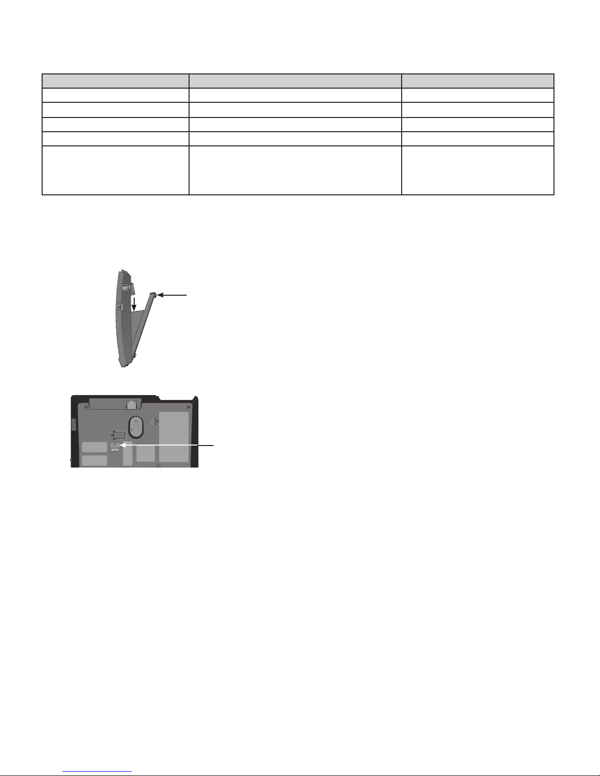
Ringer tone
There are 3 ringer tone options.
To change the ringer tone:
Turn the telephone base over with the bottom side facing up. Remove the mounting bracket if it is in desktop position. To remove
1.
the mounting bracket, rmly push both tabs downward and pull up until they release from the grooves.
Mounting
bracket
Administrator only
Slide the ringer tone switch to select the desired detented position using a narrow object such as a standard screwdriver.
2.
Ringer tone
switch
Install the mounting bracket accordingly.
3.
Flash
There are 3 ash duration options that can be programmed.
To change the ash duration:
Remove the faceplate and overlay if they are on the telephone base. Lift the handset, then press the recessed PROGRAM key.
1.
The MUTE key ashes when in administrator mode.
Press FLASH and you hear 3 beeps. Then press a dialing key, 1 (100ms), 2 (300ms) or 3 (600ms), to select the desired ash
2.
duration. Press the recessed PROGRAM key again. You hear 3 rising beeps as conrmation.
4
Page 5

Voicemail voltage detection
There are 3 options to set the voicemail voltage detection on the telephone base.
To disable the voicemail voltage detection:
Remove the faceplate and overlay if they are on the telephone base. Then remove the sticker on the telephone base.
1.
Use a narrow object to unplug all the jumpers from the telephone base.
2.
Place the sticker back in place.
3.
To set the voicemail voltage detection by the periodic low voltage pulse detection method:
Remove the faceplate and overlay if they are on the telephone base. Then remove the sticker on
1.
Jumper
the telephone base.
Use a narrow object to unplug all the jumpers from the telephone base. Then plug the jumpers into
2.
1, 2
and 3.
Place the sticker back in place.
3.
1 2 3 4
To set the voicemail voltage detection by the steady high voltage and periodic high voltage
pulse detection method:
Remove the faceplate and overlay if they are on the telephone base. Then remove the sticker on
1.
the telephone base.
Use a narrow object to unplug all the jumpers from the telephone base. Then plug the jumpers into
2.
1, 2
and 4.
Place the sticker back in place.
3.
Speed Dial keys
There are up to 10 programmable guest-service (Speed Dial) keys. Program these keys to automatically dial telephone numbers or
to activate telephone system features.
To program a Speed Dial key:
Remove the faceplate and overlay if they are on the telephone base. Lift the handset, then press the recessed PROGRAM key.
1.
The MUTE key ashes when in administrator mode.
Press the desired Speed Dial key where the telephone number is to be stored. You hear 3 beeps.
2.
Enter the telephone number (up to 16 digits).
3.
To insert a pause in the stored number, press the recessed PAUSE key.
•
The telephone stores the number automatically when 16 digits are entered. When the number has less than 16 digits, press the
4.
recessed PROGRAM key again. You hear 3 rising beeps as conrmation.
To clear the programmed Speed Dial key:
Remove the faceplate and overlay if they are on the telephone base. Lift the handset, then press the recessed PROGRAM key.
1.
The MUTE key ashes when in administrator mode.
Press the Speed Dial key where the telephone number is to be deleted. You hear 3 beeps. Press the recessed PROGRAM key
2.
again. You hear 3 rising beeps as conrmation.
5
Page 6

Telephone operation
Receive a call
When there is an incoming call, the telephone rings and the MESSAGE WAITING LED ashes.
To answer a call:
Lift the corded handset from the telephone base.
Place a call
Lift the corded handset. Listen for a dial tone and then dial the desired number, or press a Speed Dial key to dial a
programmed number.
End a call
Place the corded handset in the telephone base.
Share a call
During a call, parallel telephones (telephones on the same line) can join the call.
To join a call:
During a call, lift the corded handset to join.
Volume
Listening volume and ringer volume can be adjusted from the telephone base.
To adjust the listening volume:
During a call, press +/VOLUME or -/VOLUME to adjust the listening volume. The next call returns to the default listening volume.
To adjust the ringer volume:
At any time, slide the RINGER VOL switch on the right side of the telephone base to adjust the ringer volume.
Call waiting
When you hear a call waiting tone during a call, press FLASH on the telephone base to put your current call on hold and take
1.
the new incoming call.
Press FLASH or the switch hook once rapidly at any time to switch back and forth between calls.
2.
Mute
To mute the microphone:
During a call, press MUTE on the telephone base. The MUTE key illuminates when the mute function is turned on. You can hear
1.
the party on the other end but they cannot hear you.
Press MUTE again to resume the conversation. The light on the MUTE key turns off.
2.
6
Page 7

Important safety instructions
When using your telephone equipment, basic safety precautions should always be followed to reduce the risk of re, electric shock
and injury, including the following:
This product should be installed by a qualied technician.
1.
This product should only be connected to the host equipment and never directly to the network such as Public Switch Telephone
2.
Network (PSTN) or Plain Old Telephone Services (POTS).
Read and understand all instructions.
3.
Follow all warnings and instructions marked on the product.
4.
Unplug this product from the wall outlet before cleaning. Do not use liquid or aerosol cleaners. Use a damp cloth for cleaning.
5.
Do not use this product near water such as near a bath tub, wash bowl, kitchen sink, laundry tub or swimming pool, or in a wet
6.
basement or shower.
Do not place this product on an unstable table, shelf, stand or other unstable surfaces.
7.
Slots and openings in the back or bottom of the telephone base and handset are provided for ventilation. To protect them from
8.
overheating, these openings must not be blocked by placing the product on a soft surface such as a bed, sofa or rug. This
product should never be placed near or over a radiator or heat register. This product should not be placed in any area where
proper ventilation is not provided.
This product should be operated only from the type of power source indicated on the marking label. If you are not sure of the
9.
type of power supply on the premises, consult your dealer or local power company.
Do not allow anything to rest on the power cord. Do not install this product where the cord may be walked on.
10.
Never push objects of any kind into this product through the slots in the telephone base or handset because they may touch
11.
dangerous voltage points or create a short circuit. Never spill liquid of any kind on the product.
To reduce the risk of electric shock, do not disassemble this product, but take it to an authorized service facility. Opening or
12.
removing parts of the telephone base or handset other than specied access doors may expose you to dangerous voltages or
other risks. Incorrect reassembling can cause electric shock when the product is subsequently used.
Do not overload wall outlets and extension cords.
13.
Unplug this product from the wall outlet and refer servicing to an authorized service facility under the following conditions:
14.
When the power supply cord or plug is damaged or frayed.
A.
If liquid has been spilled onto the product.
B.
If the product has been exposed to rain or water.
C.
If the product does not operate normally by following the operating instructions. Adjust only those controls that are covered
D.
by the operation instructions. Improper adjustment of other controls may result in damage and often requires extensive work
by an authorized technician to restore the product to normal operation.
If the product has been dropped and the telephone base and/or handset has been damaged.
E.
If the product exhibits a distinct change in performance.
F.
Avoid using a telephone (other than cordless) during an electrical storm. There is a remote risk of electric shock from lightning.
15.
Do not use the telephone to report a gas leak in the vicinity of the leak. Under certain circumstances, a spark may be created
16.
when the adapter is plugged into the power outlet, or when the handset is replaced in its cradle. This is a common event
associated with the closing of any electrical circuit. The user should not plug the phone into a power outlet, and should not put
a charged handset into the cradle, if the phone is located in an environment containing concentrations of ammable or amesupporting gases, unless there is adequate ventilation. A spark in such an environment could create a re or explosion. Such
environments might include: medical use of oxygen without adequate ventilation; industrial gases (cleaning solvents; gasoline
vapors; etc.); a leak of natural gas; etc.
Only put the handset of your telephone next to your ear when it is in normal talk mode.
17.
In wall mounting position, make sure to mount the telephone base on the wall by aligning the eyelets with the mounting studs of
18.
the wall plate. Then slide the telephone base down on both mounting studs until it locks into place. Refer to the full instructions
in Installation in this user guide.
CAUTION: Keep small metallic objects such as pins and staples away from the handset receiver.
19.
SAVE THESE INSTRUCTIONS
FCC, ACTA and IC regulations
FCC Part 15
This equipment has been tested and found to comply with the requirements for a Class B digital device under Part 15 of the
Federal Communications Commission (FCC) rules. These requirements are intended to provide reasonable protection against
harmful interference in a residential installation. This equipment generates, uses and can radiate radio frequency energy and, if not
installed and used in accordance with the instructions, may cause harmful interference to radio communications. However, there is
no guarantee that interference will not occur in a particular installation. If this equipment does cause harmful interference to radio
or television reception, which can be determined by turning the equipment off and on, the user is encouraged to try to correct the
interference by one or more of the following measures:
Reorient or relocate the receiving antenna.
•
Increase the separation between the equipment and receiver.
•
Connect the equipment into an outlet on a circuit different from that to which the receiver is connected.
•
Consult the dealer or an experienced radio/TV technician for help.
•
Changes or modications to this equipment not expressly approved by the party responsible for compliance could void the user’s
authority to operate the equipment.
This device complies with Part 15 of the FCC rules. Operation is subject to the following two conditions: (1) this device may not
cause harmful interference, and (2) this device must accept any interference received, including interference that may cause
undesired operation.
This Class B digital apparatus complies with Canadian ICES-003.
7
Page 8

FCC Part 68 and ACTA
This equipment complies with Part 68 of the FCC rules and with technical requirements adopted by the Administrative Council for
Terminal Attachments (ACTA). The label on the back or bottom of this equipment contains, among other things, a product identier
in the format US:AAAKXNANXXXX. This identier must be provided to your telephone service provider upon request.
The plug and jack used to connect this equipment to premises wiring and the telephone network must comply with applicable Part
68 rules and technical requirements adopted by ACTA. A compliant telephone cord and modular plug is provided with this product.
It is designed to be connected to a compatible modular jack that is also compliant. An RJ11 jack should normally be used for
connecting to a single line and an RJ14 jack for two lines. See the installation instructions in the user guide.
The Ringer Equivalence Number (REN) is used to determine how many devices you may connect to your telephone line and still
have them ring when you are called. The REN for this product is encoded as the 6th and 7th characters following the US: in the
product identier (e.g., if ## is 03, the REN is 0.3). In most, but not all areas, the sum of all RENs should be ve (5.0) or less. For
more information, please contact your telephone service provider.
This equipment may not be used with Party Lines. If you have specially wired alarm dialing equipment connected to your telephone
line, ensure the connection of this equipment does not disable your alarm equipment. If you have questions about what will disable
alarm equipment, consult your telephone service provider or a qualied installer.
If this equipment is malfunctioning, it must be unplugged from the modular jack until the problem has been corrected. Repairs
to this telephone equipment can only be made by the manufacturer or its authorized agents. For repair procedures, contact your
local distributor.
If this equipment is causing harm to the telephone network, your telephone service provider may temporarily discontinue your
telephone service. Your telephone service provider is required to notify you before interrupting service. If advance notice is not
practical, you will be notied as soon as possible. You will be given the opportunity to correct the problem and your telephone
service provider is required to inform you of your right to le a complaint with the FCC. Your telephone service provider may make
changes in its facilities, equipment, operation, or procedures that could affect the proper functioning of this product. Your telephone
service provider is required to notify you if such changes are planned.
If this product is equipped with a corded or cordless handset, it is hearing aid compatible.
If this product has memory dialing locations, you may choose to store emergency telephone numbers (e.g., police, re, medical) in
these locations. If you do store or test emergency numbers, please:
Remain on the line and briey explain the reason for the call before hanging up.
Perform such activities in off-peak hours, such as early morning or late evening.
When the adjunct is used with a leased system, permission of the owner of the equipment must be obtained for connection of the
adjunct because modication of the host system is often required.
This product can only be connected to the host equipment and never directly to the network.
Industry Canada
Operation is subject to the following two conditions: (1) this device may not cause harmful interference, and (2) this device must
accept any interference, including interference that may cause undesired operation.
The term ‘’IC:‘’ before the certication/registration number only signies that the Industry Canada technical specications were met.
This product meets the applicable Industry Canada technical specications.
Technical specications
Power requirement Line powered 24V or 48V
Message waiting signal Steady/periodic high voltage pulse or periodic low voltage pulse
Speed Dial memory Telephone base: up to 10 memory locations; up to 16 digits
Size Telephone base: 8.03 x 5.98 x 3.74 in (204 x 152 x 95 mm)
Corded handset: 8.39 x 1.85 x 1.58 in (213 x 47 x 40 mm)
VTECH TELECOMMUNICATIONS LTD.
A member of THE VTECH GROUP OF COMPANIES.
Distributed in the U.S.A. by VTech Communications, Inc., Beaverton, Oregon 97008.
Distributed in Canada by VTech Technologies Canada Ltd., Richmond, B.C. V6W 1L5.
VTech is the registered trademark of VTech Holdings Limited.
Copyright © 2011 for VTECH TELECOMMUNICATIONS LTD.
All rights reserved. Printed in China.
96-008096-010-100
8
 Loading...