

VQ VQAA040G, VQAA040B Instruction Manuals
RADIO CONTROL MODEL
INSTRUCTION MANUAL
SPECIFICATIONS
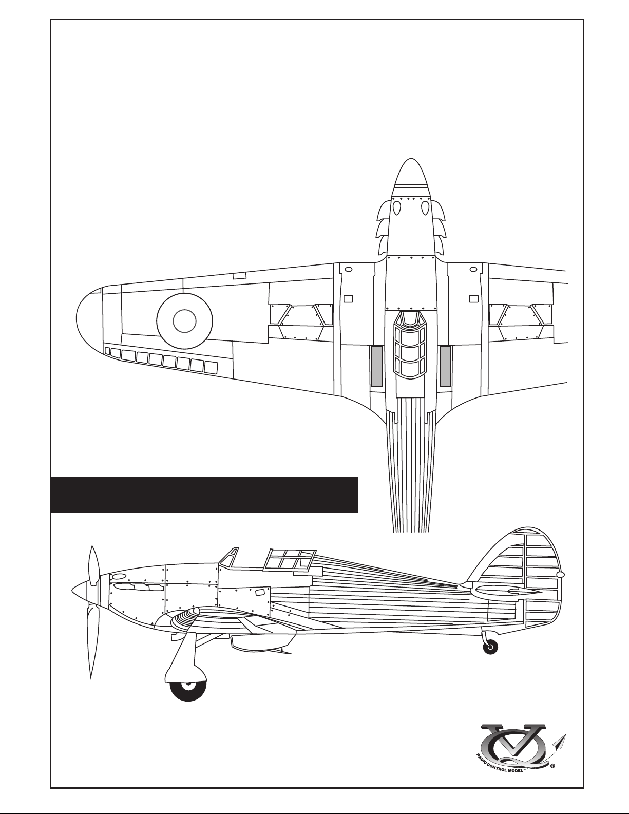
Wingspan.......63 in. / 161cm
Length............50 in. / 129cm
Engine.............50~60 2T / 70~90 4T
Or Electric equivalent.
WARNING!
This radio control model is not a toy. If modified or flow carelessly it could go out of control
and cause serious bodily injury or property damage.
Before flying your airplane, ensure the air field is spacious enough.
Always fly it outdoors in safe areas with no debris or obstacles.
Almost ready to fly
HURRICANE
VQAA040G
VQAA040B
RC Functions:
Motor - Rudder - Aileron - elevator
Flap - Retract landing gear
1.5mm
A
B
!
CA
L/R
Assemble left and right
sides the same way.
X
Drill holes using the stated
size of drill
(in this case 1.5 mm Ø)
Use epoxy glue
Take particular care here
Hatched-in areas:
remove covering
film carefully
Not included.
These parts must be
purchased separately
Check during assembly that these
parts move freely, without binding
Apply cyano glue
The pre-covered film on ARF kit may wrinkle due to variations
of temperature. Smooth out as explained right.
* Use an iron or heat gun. Start as low setting. Increase the
setting if necsessary. If it is too high, you may damage the
film
Low setting
SILICON
EPOXY A
EPOXY B
CA
GLUE
Epoxy Glue ( 5 minute type)
Silicon sealer
Cyanoacrylate
Glue
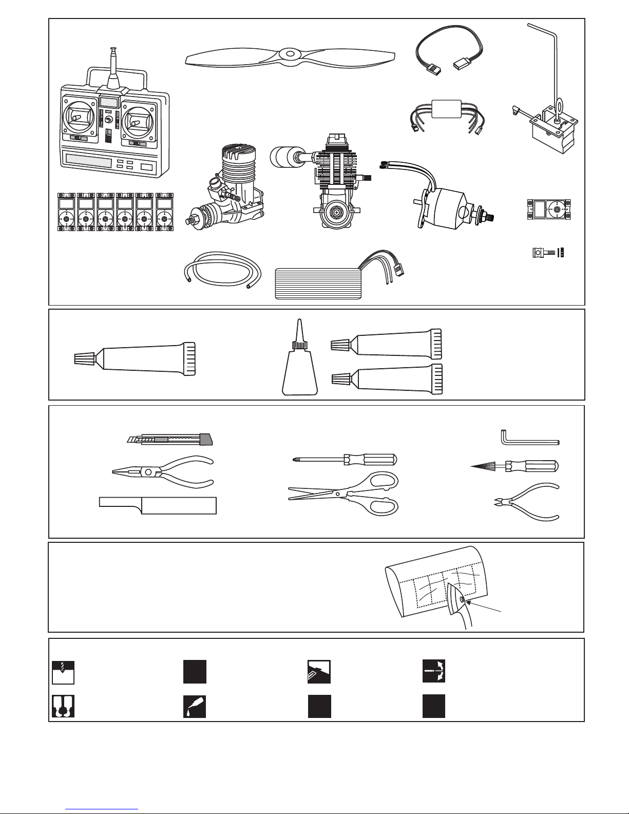
Minimum 6 channel radio
for airplane with 6 servos
.70 ~.90 - 4 cycle
12x6 for .60 - 2 cycle engine
13x6 for .70 - 4 cycle engine
14x6 for .90 - 4 cycle engine
14x8 ~ 15x8 - Brushless Motor
Silicone tube
Extension for aileron
servo, retract servo.
.50 ~ .60 - 2 cycle
REQUIRED FOR OPERATION (Purchase separately)
Linkage Stopper x2
(for retract servo)
Epoxy Glue (30 minute type)
TOLLS REQUIRED
Hobby knife
Needle nose Pliers
Phillip screw driver
Awl
Scissors
Wire Cutters
(Purchase separately)
Hex Wrench
.........................................................
.........................................................
.........................................................
.........................................................
.........................................................
.........................................................
.........................................................
.........................................................
.........................................................
.........................................................
.........................................................
Sander
Masking tape - Straight Edged Ruler - Pen or pencil - Rubbing alcohol - Drill and Assorted Drill Bits
Read through the manual before you begin, so you will have an overall idea of what to do.
Symbols used throughout this instruction manual, comprise:
(Purchase separately)
Retract landing
gear
VQAR06
Retract servo
x1
.Motor control x1 .Aileron x2
.Elevator x1 .Rudder x1
-Flap x1
Quantum 4120/07
Brushless Motor
or equivalent.
Brushless
Motor Control
Li-Po Battery.
CONVERSION TABLE
1.0mm = 3/64”
1.5mm = 1/16”
2.0mm = 5/64”
2.5mm = 3/32”
3.0mm = 1/8”
4.0mm = 5/32”
5.0mm = 13/64”
6.0mm = 15/64”
10mm = 13/32”
12mm = 15/32”
15mm = 19/32”
20mm = 51/64”
25mm = 1”
30mm = 1-3/16”
45mm = 1-51/64”
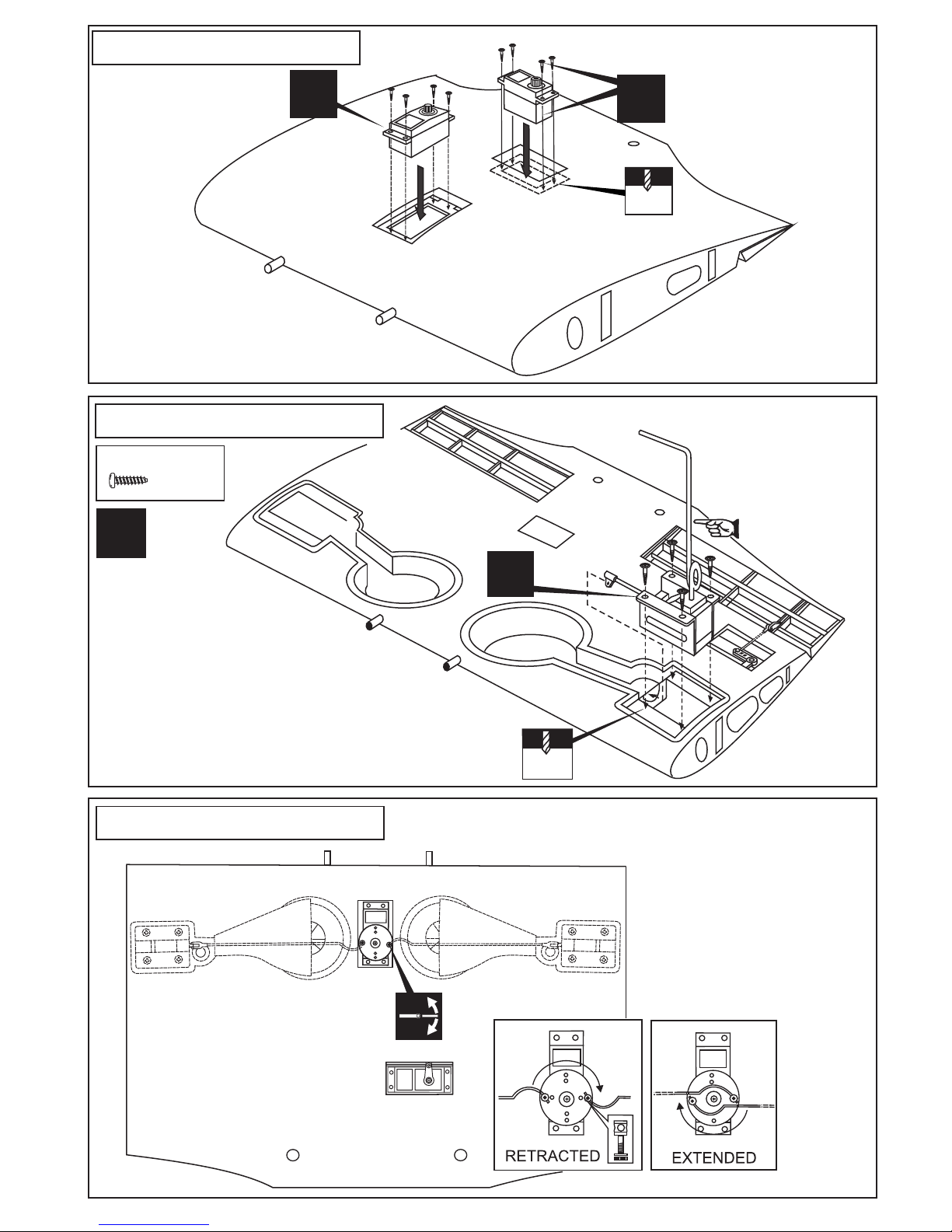
1- Retract / Flap servo
5/64
Flap servo
X
Retract servo
X
CENTER WING - TOP VIEW
3- Retract landing gear
L/R
3x12mm screw
..........8
X
2- Retract landing gear
CENTER WING - BOTTOM VIEW
Bend wire for
smooth retracting
CENTER WING - TOP VIEW
5/64
Ensure smooth
non-binding movement
Trial fit the push rod into
the wing. Join the pushrod to
the retract gear arm and trial fit
the retract into the wing.
Pull and push the retract push rod by hand
to be sure to adjust the stroke so that the landing
gear locks in both up and down position.
After checking that the retract works smoothly with the
servos, fix the retract on the wing with 3x12mm screws
Link the servo and retract gear
arm with push rod.
Be sure to adjust the stroke so
that the landing gear locks in
both up and down position.
Included with the radio set.
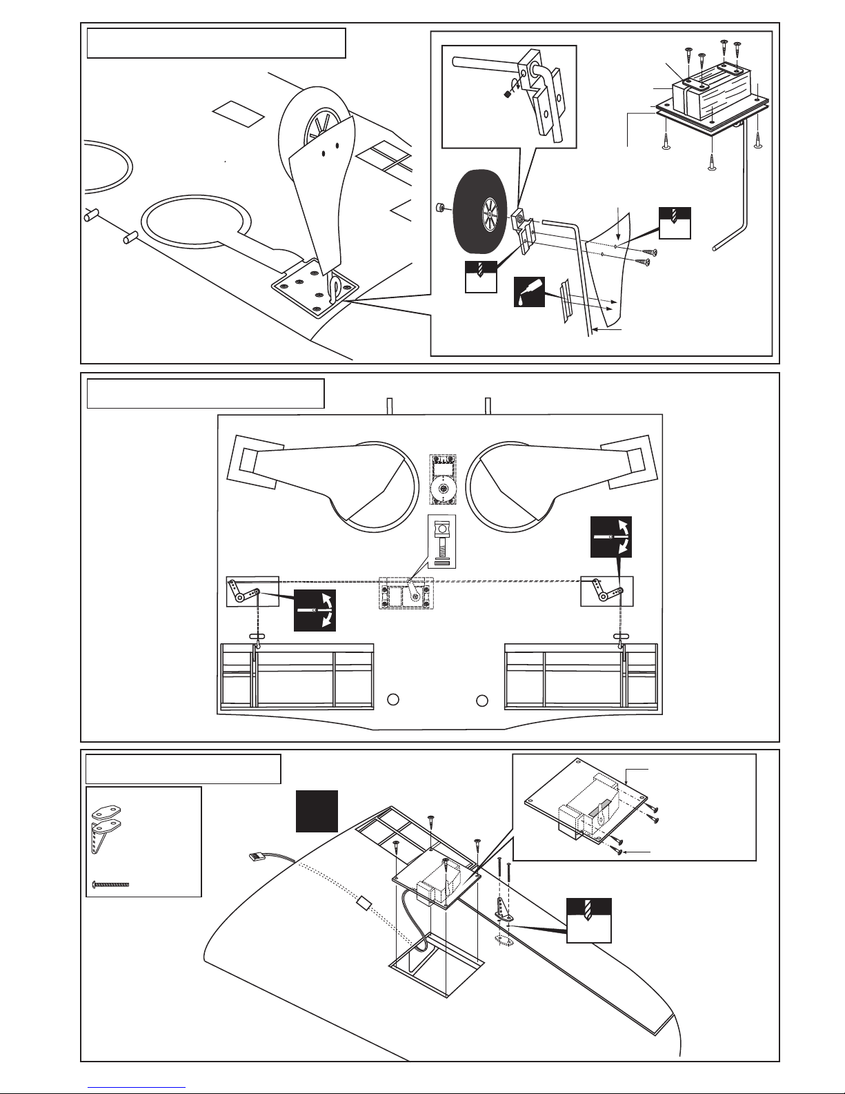
CA
ABS gear cover
ABS gear strap
2x3mm screw
Plastic strap
Main landing gear
Gear mount
(hard wood)
Ply gear mount
plate
Square plastic
3x10mm
3x10mm
2x12mm
4-Center wing - Fix gear
Main landing gear
FIX GEAR INSTALLATION
5- Center wing - Flap
CENTER WING - BOTTOM VIEW
6- Aileron servo
X
Plastic control horn
....................2
2x30mm screw
...............4
5/64
Included with the
radio set
Aileron servo
hatch (ply 3mm)
Aileron servo
extension
cord
CENTER WING - BOTTOM VIEW
Ensure smooth non-binding
movement
1/16
5/64
5/64(2x10mm)
screw
5/64(2x20mm)
screw
 Loading...