

VQ VQA05 Tuskegee, VQA06 Shangri-la Instuction Manual
RADIO CONTROL MODEL / RC FLUGMODELL
46 Class
(2T Engine)
NORTH AMERICAN
70 Class
(4T Engine)
Or Electric equivalent
Instruction manual /
ALL BALSA, PLYWOOD CONSTRUCTION AND ALMOST READY TO FLY
“TUSKEGEE”
Montageanleitung
Airman
VQA05 “Tuskegee”
474976
VQA06 “Shangri-la”
SPECIFICATIONS
Wingspan 1580mm
Length 1180mm
Electric Motor 870 Watt
Glow Engine .46 2-T / .70 4-T
Radio 4-5 Channel / 4-5 Servos
TECHNISCHE DATEN
Spannweiter 1580mm
Lange 1180mm
Elektroantrieb 870 Watt
Verbrennerantrieb 7.5cc 2-T / 11cc 4-T
Fernsteuerung 4-5 Kanal / 4-5 Servos
WARNING! This radio controlled model is NOT a toy. If modified or flown carelessly it could go out of controll and
cause serious human injury or property damage. Before flying your airplane, ensure the air field is spacious enough.
Always fly it outdoors in safe areas and seek professional advice if you are unexperienced.
ACHTUNG! Dieses ferngesteuerte Modell ist KEIN Spielzeug! Es ist für fortgeschrittene Modellflugpiloten bestimmt,
die ausreichende Erfahrung im Umgang mit derartigen Modellen besitzen Bei unsachgemäßer Verwendung kann
hoher Personen- und/oder Sachschaden entstehen. Fragen Sie in einem Modellbauverein in Ihrer Nähe um
professionelle Unterstützung, wenn Sie Hilfe im Bau und Betrieb benötigen. Der Zusammenbau dieses Modells ist
durch die vielen Abbildungen selbsterklärend und ist für fortgeschrittene, erfahrene Modellbauer bestimmt.
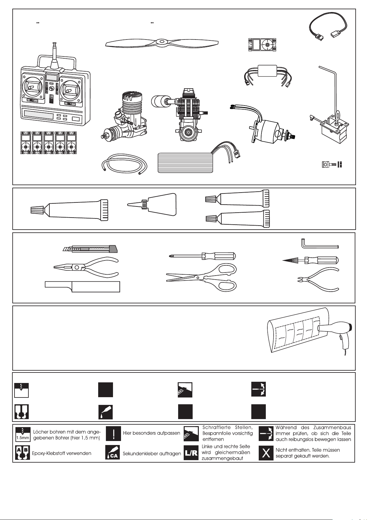
REQUIRED FOR OPERATION (Purchase separately)
BENOTIGTE KOMPONENTEN FUR DEN ABFLUG (Nicht enthalten)
10.5x6 for .40 - 2 cycle engine
11x6 for .46 - 2 cycle engine
12x6 for .60 - 4 cycle engine
12x7 for .70 - 4 cycle engine
13x6 for Quantum 4120/05
Retract servo x1
Phoenix-60 Brushless
Motor Control
Extension for aileron,
retract servo and
receiver battery pack.
.46 ~ .50 - 2 cycle
.60 ~.70 - 4 cycle
Minimum 5 channel radio
for airplane with 5 servos
.Motor control x1 .Aileron x2
.Elevator x1 .Rudder x1
GLUE
(Purchase separately)
SILICON
Silicon sealer
TOLLS REQUIRED
Hobby knife
Silicone tube
Cyanoacrylate Glue
(Purchase separately)
Li-Po Battery, 14.8V, 4000mAH, 80A
CA
Phillip screw driver
Needle nose Pliers
Scissors
Sander
.........................................................
.........................................................
.........................................................
.........................................................
.........................................................
.........................................................
.........................................................
.........................................................
.........................................................
.........................................................
.........................................................
Masking tape - Straight Edged Ruler - Pen or pencil - Rubbing alcohol - Drill and Assorted Drill Bits
If exposed to direct sunlight and/or heat, wrinkels can appear. Storing the
model in a cool place will let the wrinkles disappear. Otherwise, remove
wrinkles in covering film with a hair dryer, starting with
low temperature. You can fix the corners by using a hot iron.
Quantum 4120/05
Brushless Motor
or equivalent.
EPOXY A
EPOXY B
Retract landing
gear
Linkage Stopper x2
(for retract servo)
Epoxy Glue ( 5 minute type)
Epoxy Glue (30 minute type)
Hex Wrench
Awl
Wire Cutters
VQAR03
Bei Sonneneinstrahlung und/oder Wärme kann die Folie erschlaffen bzw. Falten
entstehen. Verwenden Sie ein Warumluftgebläse (Haartrockner) um evtl. Falten aus der Folie
zu bekommen. Die Kanten können Sie mit einem Bügeleisen behandeln. Nicht zuviel Hitze anwenden !
Symbols used throughout this instruction manual, comprise:
Drill holes using the stated
1.5mm
size of drill
(in this case 1.5 mm Ø)
A
B
Use epoxy glue
Take particular care here
!
Apply cyano glue
CA
Hatched-in areas:
remove covering
film carefully
Assemble left and right
L/R
sides the same way.
Check during assembly that these
parts move freely, without binding
Not included.
These parts must be
X
purchased separately
Read through the manual before you begin, so you will have an overall idea of what to do.
CONVERSION TABLE
1.0mm = 3/64”
1.5mm = 1/16”
2.0mm = 5/64”
2.5mm = 3/32”
3.0mm = 1/8”
4.0mm = 5/32”
5.0mm = 13/64”
6.0mm = 15/64”
10mm = 13/32”
12mm = 15/32”
15mm = 19/32”
20mm = 51/64”
25mm = 1”
30mm = 1-3/16”
45mm = 1-51/64”
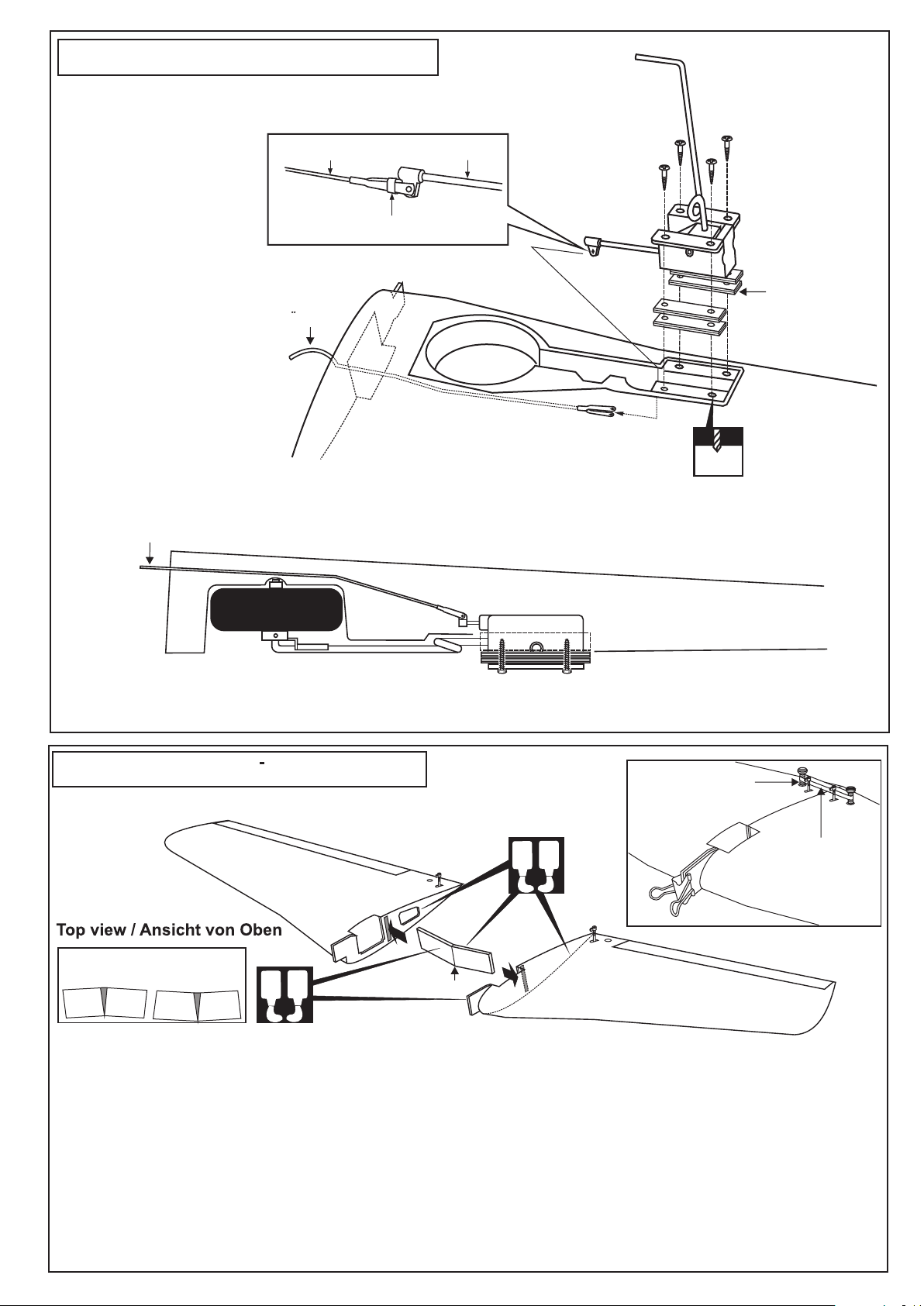
1-Retract landing gear / Einziehfahrwerk
Trial fit the push rod into the wing. Join the pushrod to the retract
gear arm and trial fit the retract into the wing.
MECHANIC RETRACT
LANDING GEAR
Retract push rod Retract gear arm
Put the nylon ring
Retract pushrod
Fahrwerkanlenkgestange
Bottom view /Ansicht von unten
After checking that the retract works smoothly, fix the retract on the wing with 3x20mm self tapping screws.
Do the same way with other half wing.
Retract pushrod
WING-TOP
3x20mm screw
(not included)
VQ-AR03 -160223
Retract (option)
Plywood buffer
included with
retract set.
2mm
FRONT-VIEW
VQ-AR03 -160223
Retract (option)
2-Joining the wing / Flachenverbindung
Nylon wing bolt
! Make sure to glue securely, If not properly glued, a failure in flight may occur.
A
B
Binder clip
Use epoxy glue to bury the
opening
1- Using a pencil, mark the center of the brace.
2- Trial fit the wing joiner into one of the wing panels. It should insert smoothly up to the center line marked above.
3- Slide the other wing half onto the dihedral brace until the wing panel meet. If the fit is over tight, it may be necessary to
lightly sand the dihedral brace.
4- Check for the correct dihedral angle.
5- Mix up some 30 minute epoxy and apply a generous amount of epoxy into the wing joiner cavity of one wing half.
6- Coat one half of the dihedral brace with epoxy up to the center line. Install the epoxy-coated side of the dihedral brace
into the wing joiner cavity up to the center line, marking sure that the “V” of the dihedral brace is positioned correctly
7- Do the same way with the other wing half.
8- Carefully slide the wing halves together, ensuring that they are accurately aligned. Firmly press the two halves
together, allowing the excess epoxy to run out. Clean off the excess epoxy with paper towel and kerosene.
IMPORTANT:
Please do not clean off the excess epoxy on the wing with strong solvent or pure alcohol, only use
kerosene to keep the colour of your model not fade.
A
B
Center line
Rubber band
(both the top
and bottom)
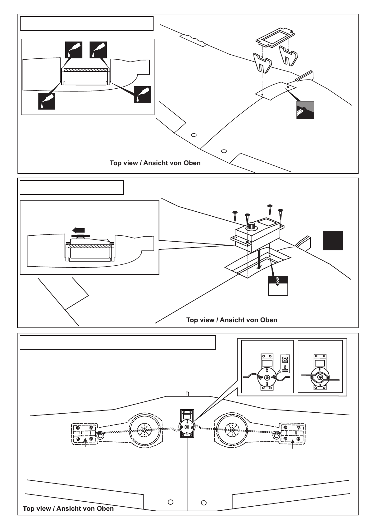
3- Servo tray / Servohalterung
Fahrwerk servohalterung
Retract servo tray
A
CENTER
WING
SECTION
CA
CA
B
BOTTOM
Retract servo tray installation
CA
A
C
CA
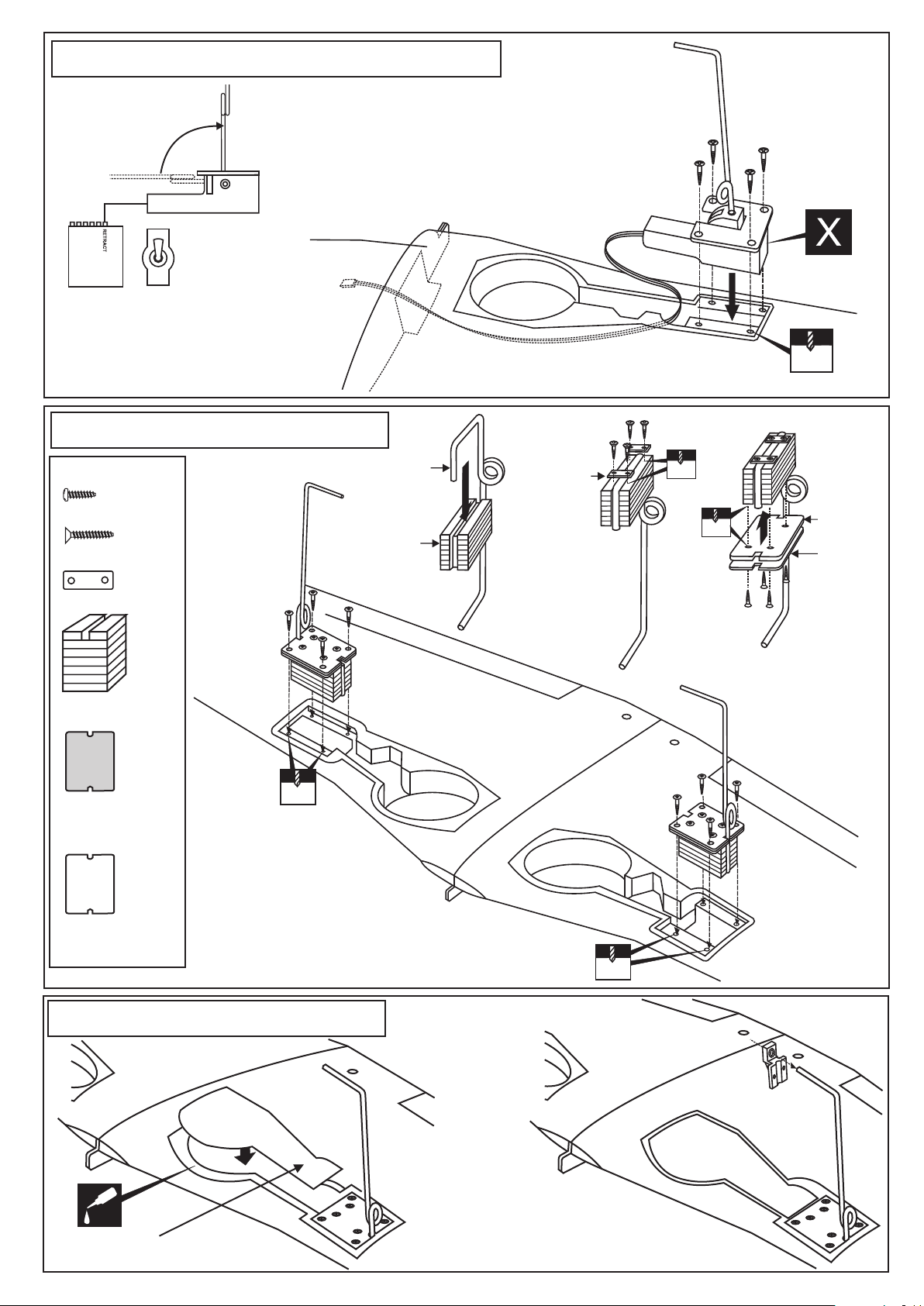
4- Servo Installation
RETRACT SERVO INSTALLATION
Note: The head of servo should be positioned
toward the rear of the wing.
Retract servo
mount
Retract servo
mount
B
Cut away only
the covering
Schneiden Sie etwas Folie weg
Install the retract servo onto the retract servo mount
and secure it in place with four screw (included with radio set).
Fahrwerkservo
Retract landing gear
servo
C
CENTER
WING
SECTION
BOTTOM
5- Retract landing gear linkage / Ruderanlenkung
With the retract and retract servo in the retracted position, mark the
position where each of the pushrod will attach to the servo arm, a small
piece of masking tape works well for this. Cut off the excess length
each rod.
Link the servo and retract gear arm with push rod.
Be sure to adjust the stroke so that the landing
gear locks in both up and down position.
Retract servo
Fahrwerkservo
1/16”
1.5mm
RETRACTED
EINGEFAHREN
X
EXTENDED
AUSGEFAHREN
Retract gear
Retract gear
6- Electric retract landing gear / Einziehfahrwerk
EXTENDED POSITION
ELECTRIC RETRACT
LANDING GEAR
RETRACTED POSITION
ON
RECEIVER
OFF
GEAR
ELECTRIC RETRACT
LANDING GEAR
7- Fixed gear / Starres Fahrwerk
3x12mm screw
..........8
3x20mm screw
......16
Nylon gear strap
.......4
3x12mm screw
Main landing gear
Gear mount
Bottom view /Ansicht von unten
Nylon gear
strap
1
2
3x20mm
2mm
2mm
3x20mm
2mm
Ply gear
mount flat
Square
plastic
3
Gear mount x 2
Ply gear mount
2mm
plate x 2
Square plastic x 2
8- Fixed gear / Starres Fahrwerk
3x20mm screw
4
Wing - bottom view
2mm
CA
ABS Wheel well cover
Bottom view /Ansicht von unten
 Loading...