

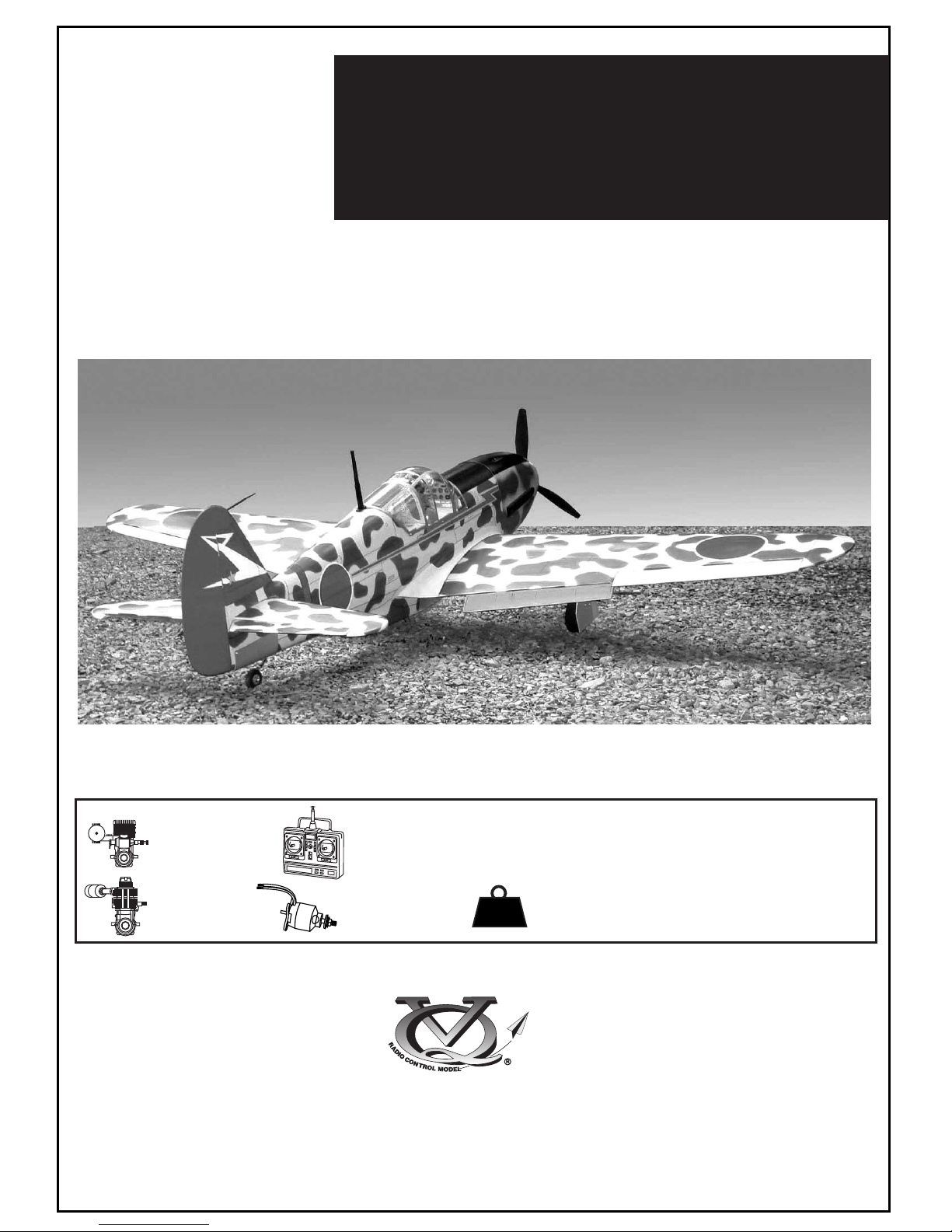
VQ KAWASAKI Ki-61 Hien “Tony”, VQA048, VQA049 Instruction Manual
90 Class
2-cycle engine
4-cycle engine
INSTRUCTION MANUAL
RADIO CONTROLED ALMOST READY-TO-FLY ENGINE POWERED ALL BALSA PLANE
Wingspan approx. 61.8 in. (1570mm)
Fuselage length approx 48.8 in. (1240mm)
6.4 lb.
(2900g)
.61
.90
6 ch.
WARNING!
This radio control model is not a toy. If modified or flow carelessly it could go out of control and cause
serious bodily injury or property damage.
Before flying your airplane, ensure the air field is spacious enough.
Always fly it outdoors in safe areas with no debris or obstacles.
Kg
or electric equivalent.
cu.in.
cu.in.
VQA048 / VQA049
KAWASAKI
Ki-61 Hien “Tony”
60 Class
10V (40A)
AEROMODELLO RADIOCOMANDATO

1.5mm
A
B
!
CA
L/R
Assemble left and right
sides the same way.
X
Drill holes using the stated
size of drill
(in this case 1.5 mm Ø)
Use epoxy glue
Take particular care here
Hatched-in areas:
remove covering
film carefully
Not included.
These parts must be
purchased separately
Check during assembly that these
parts move freely, without binding
Apply cyano glue
The pre-covered film on ARF kit may wrinkle due to variations
of temperature. Smooth out as explained right.
* Use an iron or heat gun. Start as low setting. Increase the
setting if necsessary. If it is too high, you may damage the
film
Low setting
SILICON
EPOXY A
EPOXY B
CA
GLUE
Epoxy Glue ( 5 minute type)
Silicon sealer
Cyanoacrylate
Glue
Minimum 6 channel radio for airplane
with 6 servos (EP version) and
7 servos (GP version)
.90 - 4 cycle
12x6 for .60 - 4 cycle engine
13x7 for .90 - 4 cycle engine
14X8 for Quantum 4120/07
Silicone tube
Extension for aileron
servo, retract servo.
.60 - 2 cycle
REQUIRED FOR OPERATION (Purchase separately)
Linkage Stopper x2
(for retract servo)
Epoxy Glue (30 minute type)
TOLLS REQUIRED
Hobby knife
Needle nose Pliers
Phillip screw driver
Awl
Scissors
Wire Cutters
(Purchase separately)
Hex Wrench
.........................................................
.........................................................
.........................................................
.........................................................
.........................................................
.........................................................
.........................................................
.........................................................
.........................................................
.........................................................
.........................................................
Sander
Masking tape - Straight Edged Ruler - Pen or pencil - Rubbing alcohol - Drill and Assorted Drill Bits
Read through the manual before you begin, so you will have an overall idea of what to do.
Symbols used throughout this instruction manual, comprise:
(Purchase separately)
Retract landing
gear
VQAR010
Retract servo
x1
.Motor control x1(GP version)
.Aileron x2 .Elevator x1
.Rudder x1 .Flap x 2
Quantum 4120/07
Brushless Motor
or equivalent.
Phoenix-60 Brushless
Motor Control or equivalent.
Li-Po Battery, 14.8V, 4000mAH, 80A
CONVERSION TABLE
1.0mm = 3/64”
1.5mm = 1/16”
2.0mm = 5/64”
2.5mm = 3/32”
3.0mm = 1/8”
4.0mm = 5/32”
5.0mm = 13/64”
6.0mm = 15/64”
10mm = 13/32”
12mm = 15/32”
15mm = 19/32”
20mm = 51/64”
25mm = 1”
30mm = 1-3/16”
45mm = 1-51/64”
A
B
2- Joining the wing
A
B
Draw the center line
on the wing joiner
- Trial fit each part before gluing . Be certain that there are no gaps.
If the parts will join, but with a gaps, sand or trim the parts a little at
a time until the parts meet exactly with no gaps.
- Check for the correct dihedral angle
Before gluing:
- Draw the center line on the wing joiner.
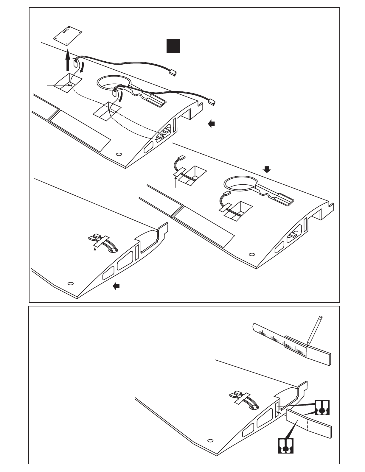
1-Aileron extension cord installation
WING BOTTOM-VIEW
Using the thread (pre-installed at factory)
to slide the aileron and flap extension cord
into the wing half.
Using the adhesive tape to secure
the one end of the aileron and flap
extension cord in place.
Using the adhesive tape to secure the one
end of the aileron and flap extension cord in place.
X
30cm Extension cord
Thread
Adhesive tape
Adhesive tape
WING BOTTOM-VIEW
WING TOP-VIEW
30 min. Epoxy
Coat one half of the dihedral brace with epoxy up
to the center line. Install the epoxy-coated side of
the dihedral brace into the wing joiner cavity up to
the center line.
Aileron servo hatch
Turn the screws and full the aileron and
flap servo hatch out of the wing half.
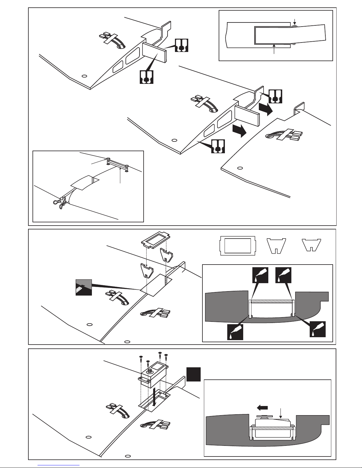
Cut away only
the film
TOP-VIEW
A
B
C
B
C
A
CENTER
WING
SECTION
CA
CA
CA
CA
BOTTOM
Retract servo tray
Retract servo mount
Retract servo mount “B”is longer than “C”
Note:
TOP-VIEW
CENTER
WING
SECTION
BOTTOM
Retract servo
Retract servo
X
Install the retract servo onto the retract
servo mount and secure it in place with
four screw (included with radio set).
Note: The head of servo should be positioned
toward the rear of the wing.
RETRACT SERVO INSTALLATION
A
B
C
Retract servo tray
Retract servo mount
Carefully slide the wing halves together,
ensuring that they are accurately aligned.
Firmly press the two halves together,
allowing the excess epoxy to run out.
Note: The two wing halves roots must
fit together perfectly.
Clear off the excess epoxy.
! Make sure to glue securely, If not properly glued,
a failure in flight may occur.
Glue must go inside
Wing joiner
Glue
Wing half
Hold the wing halves together with paper
clamp and rubber band.
IMPORTANT:
Please do not clean off the excess epoxy on the
wing with strong solvent or pure alcohol, only use kerosene to
keep the colour of your model not fade.
A
B
A
B
30 min. Epoxy
WING TOP-VIEW
Rubber band
(not include)
Paper clamp
(not include)
Nylon wing bolt
(included)
WING TOP-VIEW
3- Joinning the wing
A
B
A
B
30 min. Epoxy
WING TOP-VIEW
4-Retract servo mount
5- Retract servo
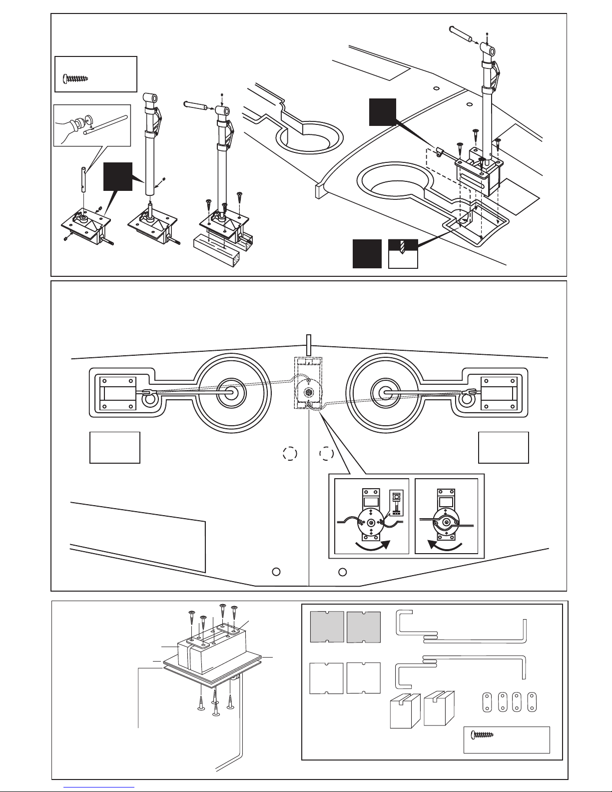
BOTTOM VIEW
RETRACTED
EXTENDED
Link the servo and retract gear arm with push rod. Be sure to adjust the stroke so that the landing gear locks in both up
and down position.
With the retract and retract servo in the retracted position, mark the position
where each of the pushrod will attach to the servo arm, a small piece of
masking tape works well for this. Cut off the excess length each rod.
Plastic strap
Main landing gear
Gear mount
(plywood)
Ply gear mount
plate
Square plastic
3x20mm
3x20mm
Ply gear mount plate
Square plastic
Main gear (left)
Main gear (right)
Gear mount
(plywood)
Plastic strap
3x20mm screw..16
L/R
3x15mm viti
..........8
X
5/64”
2mm
1
2
STEP
STEP
Note: Struts and retract not included.
3x15mm
..........8
3
STEP
X
6- Retract and struts
7- Retract linkage
8- Fixed gear
BOTTOM VIEW
 Loading...