

VQ T-34 Mentor Instruction Manaul
SPECIFICATIONS
Wingspan:.........................1560mm (61.4in)
Length:................................1170mm (46 in)
Electric Motor:.....................See next pager
Glow Engine:.................... .46 2-T / .70 4-T
RTF Weight: 3.2Kg / 7.05lbs (Will vary with
Equipment Used).
Radio:......................6 Channel / 6-7 Servos
Function: Ailerons-Elevator-Rudder-Throttle
Flaps-Optional Retractable Landing Gear.
WARNING! This radio controlled model is NOT a toy. If modified or flown carelessly it could go out of controll and
cause serious human injury or property damage. Before flying your airplane, ensure the air field is spacious enough.
Always fly it outdoors in safe areas and seek professional advice if you are unexperienced.
ACHTUNG! Dieses ferngesteuerte Modell ist KEIN Spielzeug! Es ist für fortgeschrittene Modellflugpiloten bestimmt,
die ausreichende Erfahrung im Umgang mit derartigen Modellen besitzen. Bei unsachgemässer Verwendung kann
hoher Personen- und/oder Sachschaden entstehen. Fragen Sie in einem Modellbauverein in Ihrer Nähe um
professionelle Unterstätzung, wenn Sie Hilfe im Bau und Betrieb benötigen. Der Zusammenbau dieses Modells ist
durch die vielen Abbildungen selbsterklärend und ist für fortgeschrittene, erfahrene Modellbauer bestimmt.
Radio control model / Flugmodel
ALL BALSA, PLYWOOD CONSTRUCTION AND ALMOST READY TO FLY
BEECHCRAFT
MILITARY TRAINER
Instruction manual / Montageanleitung
TECHNISCHE DATEN
Spannweite:...................................1560mm
Lange:............................................1170mm
Elektroantrieb.............(siehe nächste Seite)
Verbrennerantrieb:...............7.45cc - 11.5cc
Fluggewicht:.......................................3.2Kg
Fernsteuerung.............6 Kanal / 6-7 Servos
VQ No: VQA095
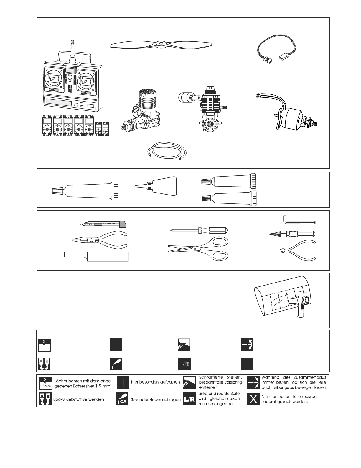
1.5mm
A
B
!
CA
L/R
Assemble left and right
sides the same way.
X
Drill holes using the stated
size of drill
(in this case 1.5 mm ÿ)
Use epoxy glue
Take particular care here
Hatched-in areas:
remove covering
film carefully
Not included.
These parts must be
purchased separately
Check during assembly that these
parts move freely, without binding
Apply cyano glue
SILICON
EPOXY A
EPOXY B
CA
GLUE
Epoxy Glue ( 5 minute type)
Silicon sealer
Cyanoacrylate Glue
Minimum 6 channel radio
for airplane with 5 (4 for EP) standard servos
and two servo mini.
.60 ~.70 - 4 cycle
10.5x6 for .40 - 2 cycle engine
11x6 for .46 - 2 cycle engine
12x6 for .60 - 4 cycle engine
12x7 for .70 - 4 cycle engine
13x7 - 13x8 for electric motor
Silicone tube
Extension for aileron
servo, retract servo
and Rx battery pack.
.46 ~ .50 - 2 cycle
Epoxy Glue (30 minute type)
TOLLS REQUIRED
Hobby knife
Needle nose Pliers
Phillip screw driver
Awl
Scissors
Wire Cutters
(Purchase separately)
Hex Wrench
.........................................................
.........................................................
.........................................................
.........................................................
.........................................................
.........................................................
.........................................................
.........................................................
.........................................................
.........................................................
.........................................................
Sander
Masking tape - Straight Edged Ruler - Pen or pencil - Drill and Assorted Drill Bits
Read through the manual before you begin, so you will have an overall idea of what to do.
Symbols used throughout this instruction manual, comprise:
(Purchase separately)
.Motor control x1(for GP) .Elevator x1
.Rudder x1. Aileron x2. Flapx2 mini servo
CONVERSION TABLE
1.0mm = 3/64”
1.5mm = 1/16”
2.0mm = 5/64”
2.5mm = 3/32”
3.0mm = 1/8”
4.0mm = 5/32”
5.0mm = 13/64”
6.0mm = 15/64”
10mm = 13/32”
12mm = 15/32”
15mm = 19/32”
20mm = 51/64”
25mm = 1”
30mm = 1-3/16”
45mm = 1-51/64”
If exposed to direct sunlight and/or heat, wrinkels can appear. Storing the
model in a cool place will let the wrinkles disappear. Otherwise, remove
wrinkles in covering film with a hair dryer, starting with
low temperature. You can fix the corners by using a hot iron.
Bei Sonneneinstrahlung und/oder Wärme kann die Folie erschlaffen bzw. Falten
entstehen. Verwenden Sie ein Warumluftgebläse (Haartrockner) um evtl. Falten aus der Folie
zu bekommen. Die Kanten können Sie mit einem Bügeleisen behandeln. Nicht zuviel Hitze anwenden !
REQUIRED FOR OPERATION (Purchase separately)
More info: www.pichler-modellbau.de
Low seting
G-46 HP Motor
5 cell 4500mAh LiPo battery
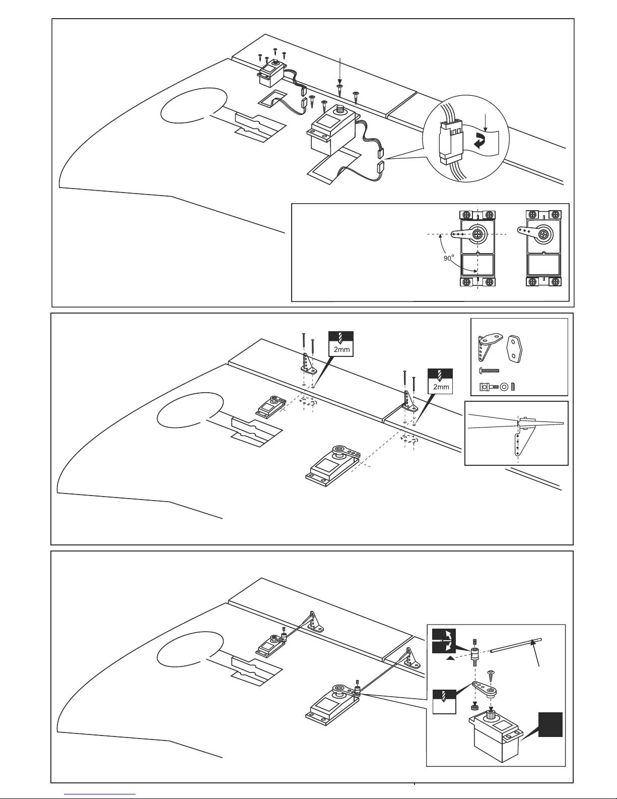
1-Cut away the covering of the wing bottom
where the aileron servo goes.
2-Connect the aileron servo cord to the aileron
extension cord.
3-Install the aileron servo on the servo mount.
-Switch on the radio (trims centered)
then mount the ailerons servo horn
in neutral position.
-The servo horn should be
perpendicular to the servo
YES
NO
1-Depending on the position of the linkage, determine the location of aileron control horn.
The horn holes must be perfectly aligned with the axis of articulation.
2-Mark the position of the “foot” of the horn on the aileron. Then, with the drill, make the 2
holes.
3-Install the aileron control horn as shown.
Included with the
radio set.
Adhesive
tape
Plastic control horn
..........4
2x30mm....8
..........4
Control horn Alignment
Do the same way with second
wing half.
Do the same way with second
wing half.
Do the same way with second
wing half.
X
3mm set Screw
2 mm
Aileron pushrod
D=5/64”(2mm)
1-Aileron and Flap servo
2-Aileron/Flap control horn
3-Aileron/Flap linkages
WING - BOTTOM VIEW
WING - BOTTOM VIEW
WING - BOTTOM VIEW
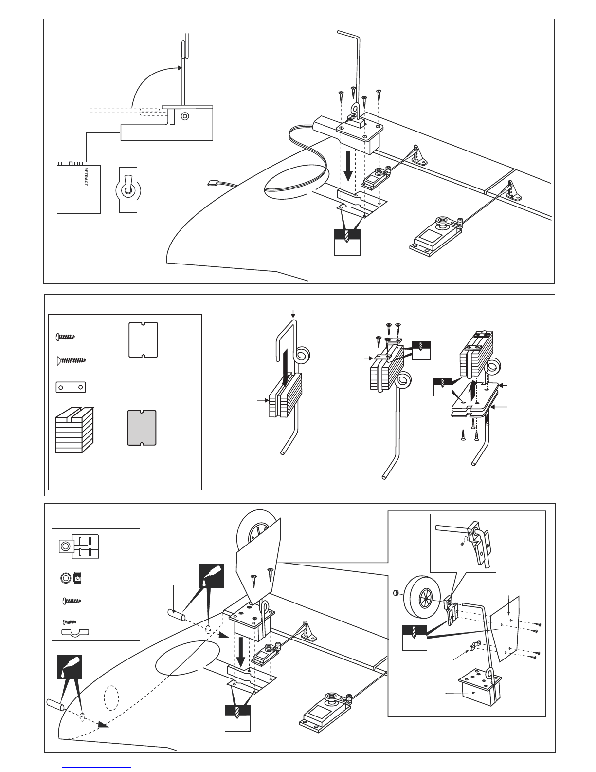
RECEIVER
ELECTRIC RETRACT
LANDING GEAR
ON
OFF
GEAR
EXTENDED POSITION
RETRACTED POSITION
2mm
2mm
1.5mm
gear cover
Gear mount
gear strap
1/16
1/8x13/32”(3x10mm)
5/64x15/64”(2x6mm)
..........8
..........8
5/32”(4mm) collar
..........2
........2
..........2
CA
Thin CA
CA
Thin CA
6x23mm
wooden dowel
4-Electric retract
6-Fixed gear installation
WING - BOTTOM VIEW
Electric retract must be purchase separately
5-Fixed gear
Ply gear mount
plate x 2
Gear mount x 2
Main landing gear
Gear mount
1
3x20mm
Nylon gear
strap
2mm
2
3x20mm
Ply gear
mount flat
Square
plastic
2mm
3
3x20mm screw
..........8
3x12mm screw
......16
Nylon gear strap
.......4
Square plastic x 2
Do the same way with
second wing half.
 Loading...