

VQ VQA120, SBD-5 Dauntless Instruction Manual
SPECIFICATIONS
Wingspan:.........................1540mm (61.4in)
Length:................................1060mm (46 in)
Electric Motor:.....................See next pager
Glow Engine:.................... .46 2-T / .70 4-T
RTF Weight: 3.2Kg / 7.05lbs (Will vary with
Equipment Used).
Radio:....................7-8 Channel / 7-8 Servos
Function: Ailerons-Elevator-Rudder-Throttle
Flaps-Optional Retractable Landing Gear.
WARNING! This radio controlled model is NOT a toy. If modified or flown carelessly it could go out of controll and
cause serious human injury or property damage. Before flying your airplane, ensure the air field is spacious enough.
Always fly it outdoors in safe areas and seek professional advice if you are unexperienced.
ACHTUNG! Dieses ferngesteuerte Modell ist KEIN Spielzeug! Es ist für fortgeschrittene Modellflugpiloten bestimmt,
die ausreichende Erfahrung im Umgang mit derartigen Modellen besitzen. Bei unsachgemässer Verwendung kann
hoher Personen- und/oder Sachschaden entstehen. Fragen Sie in einem Modellbauverein in Ihrer Nähe um
professionelle Unterstätzung, wenn Sie Hilfe im Bau und Betrieb benötigen. Der Zusammenbau dieses Modells ist
durch die vielen Abbildungen selbsterklärend und ist für fortgeschrittene, erfahrene Modellbauer bestimmt.
Radio control model / Flugmodel
ALL BALSA, PLYWOOD CONSTRUCTION AND ALMOST READY TO FLY
U.S NAVY DIVE BOMBER
Instruction manual / Montageanleitung
TECHNISCHE DATEN
Spannweite:...................................1540mm
Lange:............................................1060mm
Elektroantrieb.............(siehe nächste Seite)
Verbrennerantrieb:...............7.45cc - 11.5cc
Fluggewicht:.......................................3.2Kg
Fernsteuerung..........7-8 Kanal / 7-8 Servos
VQ No: VQA120
1.5mm
A
B
!
CA
L/R
Assemble left and right
sides the same way.
X
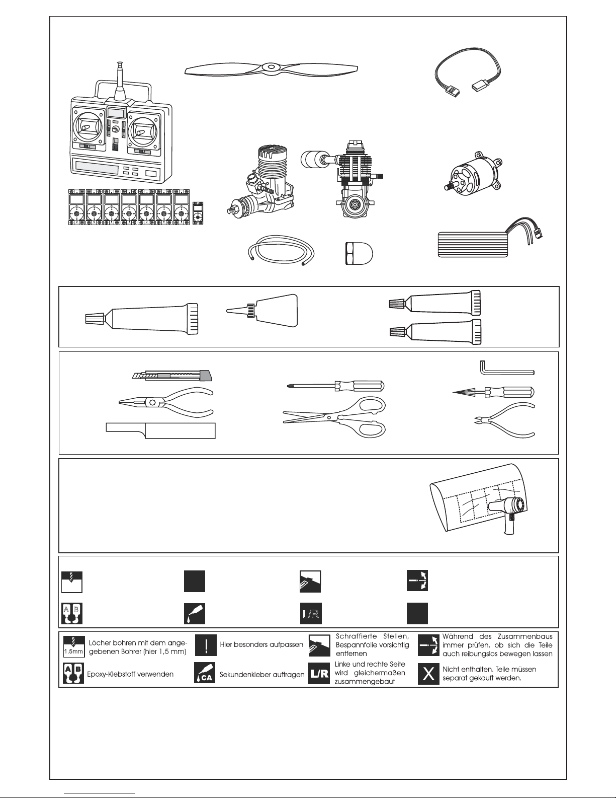
Drill holes using the stated
size of drill
(in this case 1.5 mm )
Use epoxy glue
Take particular care here
Hatched-in areas:
remove covering
film carefully
Not included.
These parts must be
purchased separately
Check during assembly that these
parts move freely, without binding
Apply cyano glue
SILICON
CA
GLUE
Silicon sealer
Cyanoacrylate Glue (thin type)
Minimum 7 channel radio
with 7 (6 for EP) standard servos
and one servo mini.
.60 ~.70 - 4 cycle
10.5x6 for .40 - 2 cycle engine
11x6 for .46 - 2 cycle engine
12x6 for .60 - 4 cycle engine
12x7 for .70 - 4 cycle engine
13x7 - 13x8 for electric motor
Silicone tube
Extension cord for aileron servos: 50cm(x2)
.46 ~ .50 - 2 cycle
TOLLS REQUIRED
Hobby knife
Needle nose Pliers
Phillip screw driver
Awl
Scissors
Wire Cutters
(Purchase separately)
Hex Wrench
.........................................................
.........................................................
.........................................................
.........................................................
.........................................................
.........................................................
.........................................................
.........................................................
.........................................................
.........................................................
.........................................................
Sander
Masking tape - Straight Edged Ruler - Pen or pencil - Drill and Assorted Drill Bits
Read through the manual before you begin, so you will have an overall idea of what to do.
Symbols used throughout this instruction manual, comprise:
(Purchase separately)
.Motor control x1(for GP) .Elevator x1
.Rudder x1. Aileron x2. R-L Flap x2
CONVERSION TABLE
1.0mm = 3/64”
1.5mm = 1/16”
2.0mm = 5/64”
2.5mm = 3/32”
3.0mm = 1/8”
4.0mm = 5/32”
5.0mm = 13/64”
6.0mm = 15/64”
10mm = 13/32”
12mm = 15/32”
15mm = 19/32”
20mm = 51/64”
25mm = 1”
30mm = 1-3/16”
45mm = 1-51/64”
If exposed to direct sunlight and/or heat, wrinkels can appear. Storing the
model in a cool place will let the wrinkles disappear. Otherwise, remove
wrinkles in covering film with a hair dryer, starting with
low temperature. You can fix the corners by using a hot iron.
Bei Sonneneinstrahlung und/oder Wärme kann die Folie erschlaffen bzw. Falten
entstehen. Verwenden Sie ein Warumluftgebläse (Haartrockner) um evtl. Falten aus der Folie
zu bekommen. Die Kanten können Sie mit einem Bügeleisen behandeln. Nicht zuviel Hitze anwenden !
REQUIRED FOR OPERATION (Purchase separately)
Low seting
700-800W Brushless Motor
5 cell 4500mAh LiPo battery
Extension cord for flap servos: 50cm(x2)
Extension cord for retract servos: 30cm(x2)
Extension cord for Rx battery pack: 20cm(x1)
.Center flap x1mini
Spinner hub
EPOXY A
EPOXY B
Epoxy Glue
(30 minute type)
2 mm
1B
1F
CA
CA
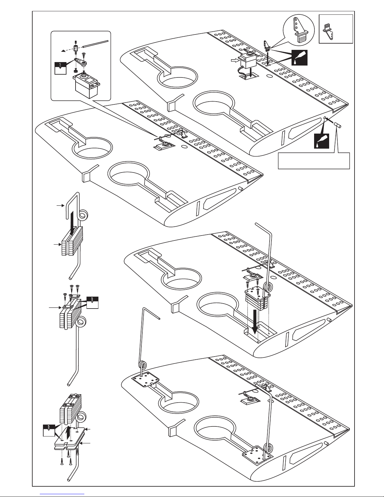
Center flap
servo
Control horn
...........1
Push the wooden dowel to the
hole up to the center line
Thin CA
Thin CA
1A
BOTTOM-VIEW
1G
BOTTOM-VIEW
Main
landing gear
Gear
mount
1C
3x20mm
Nylon gear
strap
2mm
3x20mm
Ply gear
mount flat
Square
plastic
2mm
3x15mm
BOTTOM-VIEW
1D
1E
1-WING
2A
2B
2C
CENTER
WING
SECTION
BOTTOM
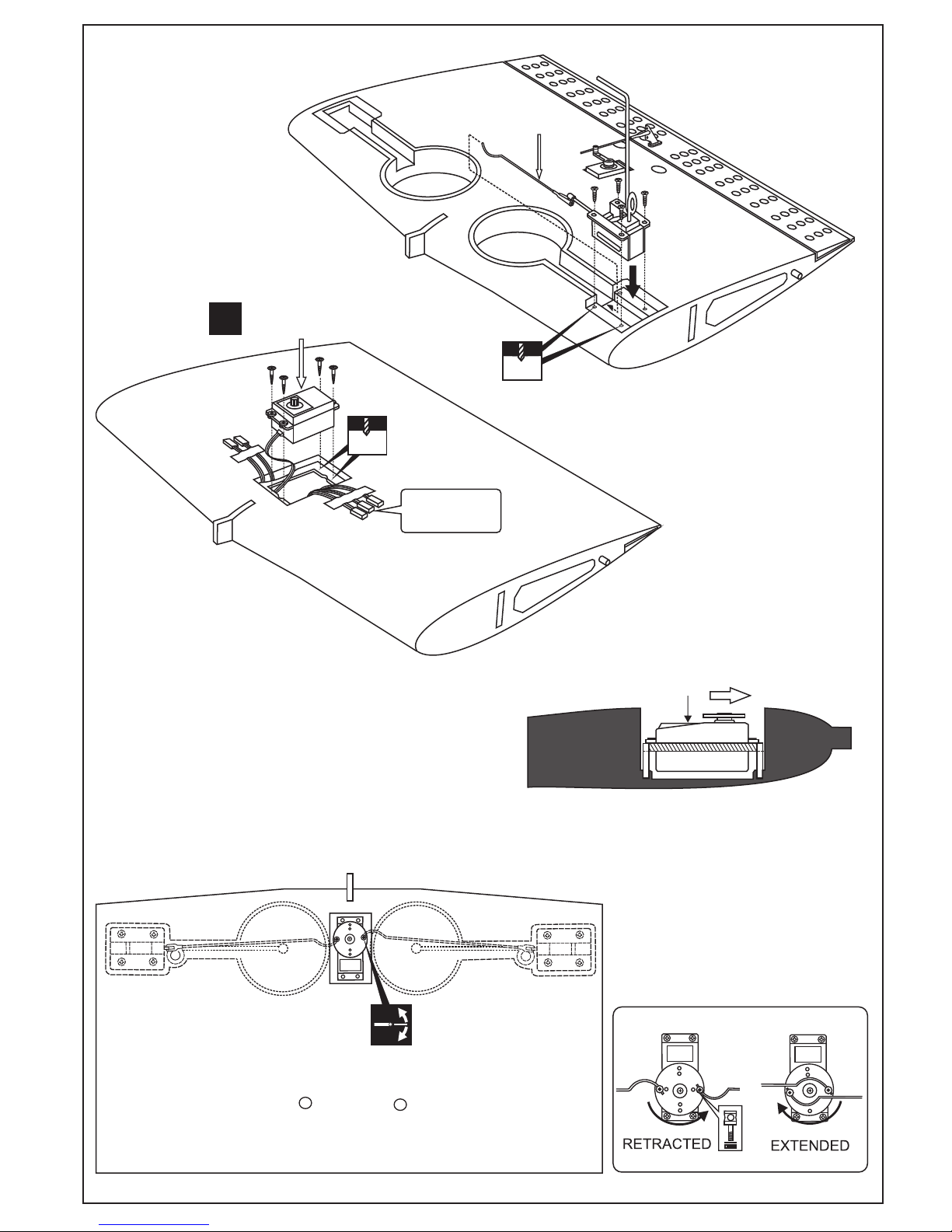
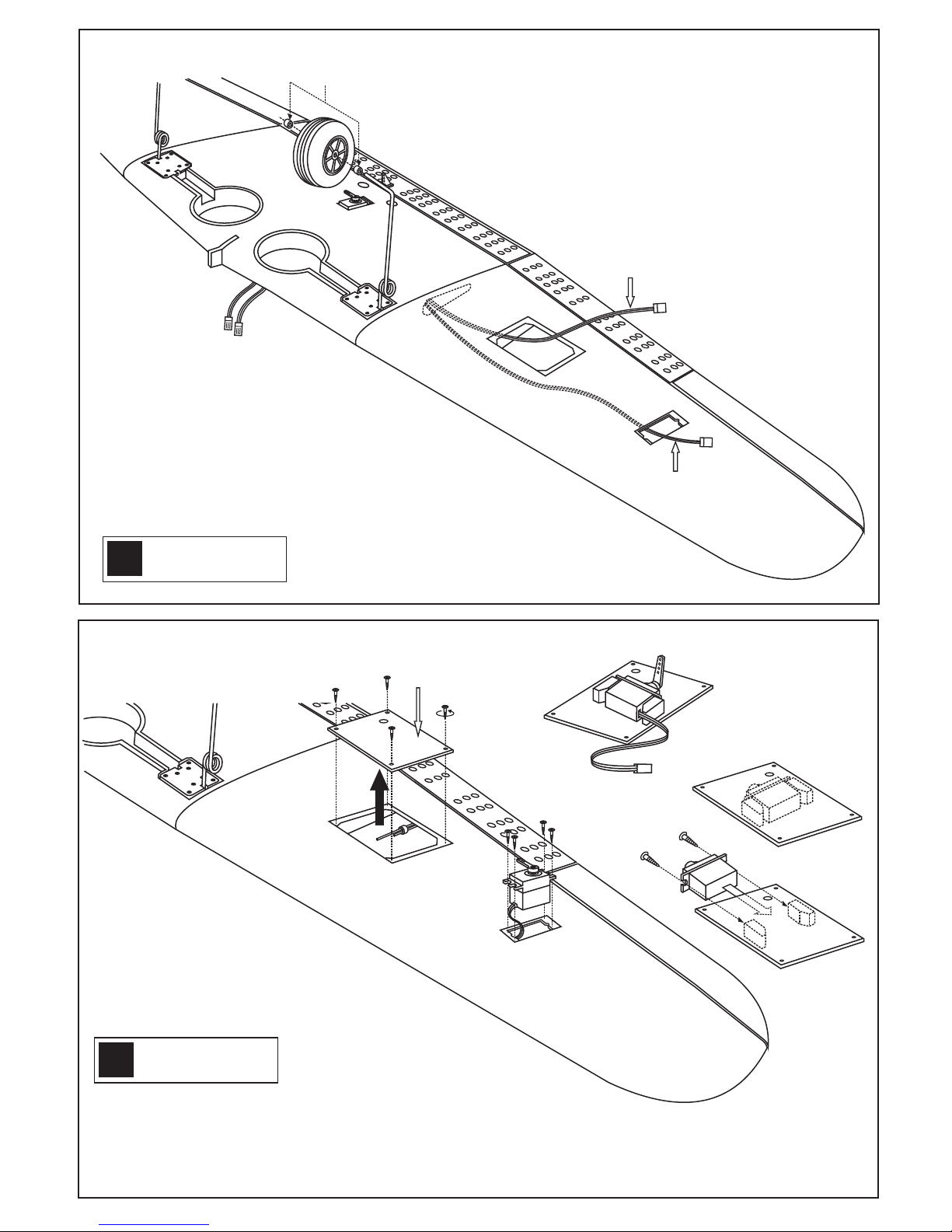
Retract servo
Retract servo
X
Install the retract servo onto the retract
servo mount and secure it in place with
four screw (included with radio set).
Note: The head of servo should be positioned
toward the front of the wing.
RETRACT SERVO INSTALLATION
1mm
TOP-VIEW
CENTER WING - TOP VIEW
Ensure smooth
non-binding movement
Link the servo and retract gear arm with
push rod.
Be sure to adjust the stroke so that the
landing gear locks in both up and down
position.
2mm
3x15mm
Retract pushrod
BOTTOM-VIEW
Aileron and flap
extension cord
2-WING
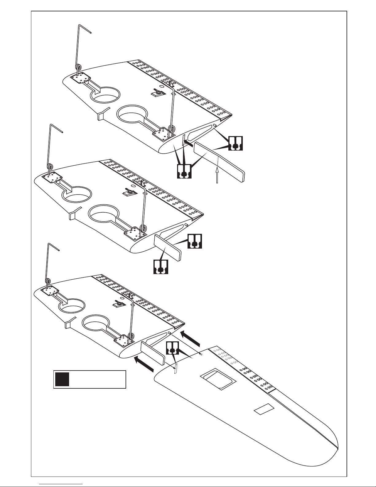
A
B
A
B
A
B
A
B
A
B
Using a pencil, mark the center of the brace.
This mark will serve as the center line when
joining the wing halves.
Coat one half of the dihedral brace with epoxy up to the center line.
Install the epoxy-coated side of the dihedral brace into the wing
joiner cavity up to the center line, making sure that the “V” of the
dihedral brace is positioned correctly.
Apply the generous amount of epoxy into the wing cavity of the center
wing.
Smear epoxy on all sides of the exposed area of the dihedral brace
and uniformly coat both wing roots with epoxy.
Carefully slide the wing halves together, ensuring that they are
accurately aligned.
Firmly press the two wing halves together, allowing the excess epoxy
to run out. Using kerosene and paper towel, clean off the excess
epoxy
WARNING: Securely glue together, if coming of
during flights, you lose control of your plane
which lead to accidents.
IMPORTANT: Please do not clean off the excess epoxy on the wing
with strong solvent or pure alcohol, only use kerosene to keep the
colour of your model not fade.
L/R
Assemble left and right
wings the same way.
3-WING
3A
3B
3C
5A
Place the aileron servo back in its mount
and secure it in place using the four screws
included with the servo (5A)
Move the flap servo hatch out of the wing (5B)
Place the flap servo (mini servo) in its mount (5C)
Finish (top view)
Finish (bottom view)
Flap servo hatch
Flap extension cord
(purchase separately)
Aileron extension cord
(purchase separately)
L/R
Assemble left and right
sides the same way.
L/R
Assemble left and right
sides the same way.
5B
5C
5D
4mm collar
4-WING
5-WING
 Loading...