

VQ FOCKE-WULF FOCKE-WULF, FOCKE-WULF FW-190A Instruction Manual
45 Class
70 Class
2-cycle engine
4-cycle engine
INSTRUCTION MANUAL
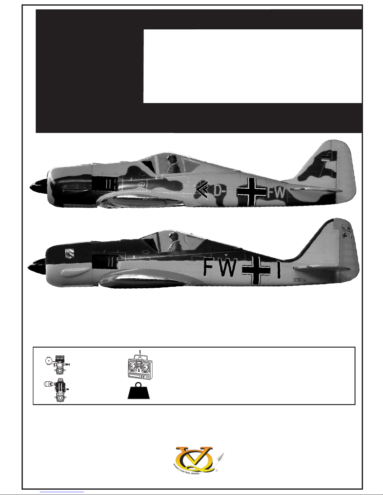
Wingspan approx. 59 in.
(1500mm)
Fuselage length approx 43 in.
(1090mm)
6 lb.
(2700g)
46~50
(7.45cc)
60~70
(11.5cc)
5~6
FW - 190A
FOCKE-WULF
VQA0450L
VQA044G/Y
Warning: This radio control model is not a toy. If modified or flow carelessly it could go out of control and cause
serious bodily injury or property damage.
Before flying your airplane, ensure the air field is spacious enough.
Always fly it outdoors in safe areas with no debris or obstacles.
RADIO CONTROL MODEL
Or Electric equivalent
TOLLS REQUIRED
Hobby knife
Needle nose Pliers
Phillip screw driver
Awl
Scissors
Wire Cutters
(Purchase separately)
Hex Wrench
.........................................................
.........................................................
.........................................................
.........................................................
.........................................................
.........................................................
.........................................................
.........................................................
.........................................................
.........................................................
.........................................................
Sander
1.5mm
A
B
!
CA
L/R
Assemble left and right
sides the same way.
X
Drill holes using the stated
size of drill
(in this case 1.5 mm Ø)
Use epoxy glue
Take particular care here
Hatched-in areas:
remove covering
film carefully
Not included.
These parts must be
purchased separately
Check during assembly that these
parts move freely, without binding
Apply cyano glue
The pre-covered film on ARF kit may wrinkle due to variations
of temperature. Smooth out as explained right.
* Use an iron or heat gun. Start as low setting. Increase the
setting if necsessary. If it is too high, you may damage the
film
Low setting
SILICON
EPOXY A
EPOXY B
CA
GLUE
Epoxy Glue ( 5 minute type)
Silicon sealer
Cyanoacrylate
Glue
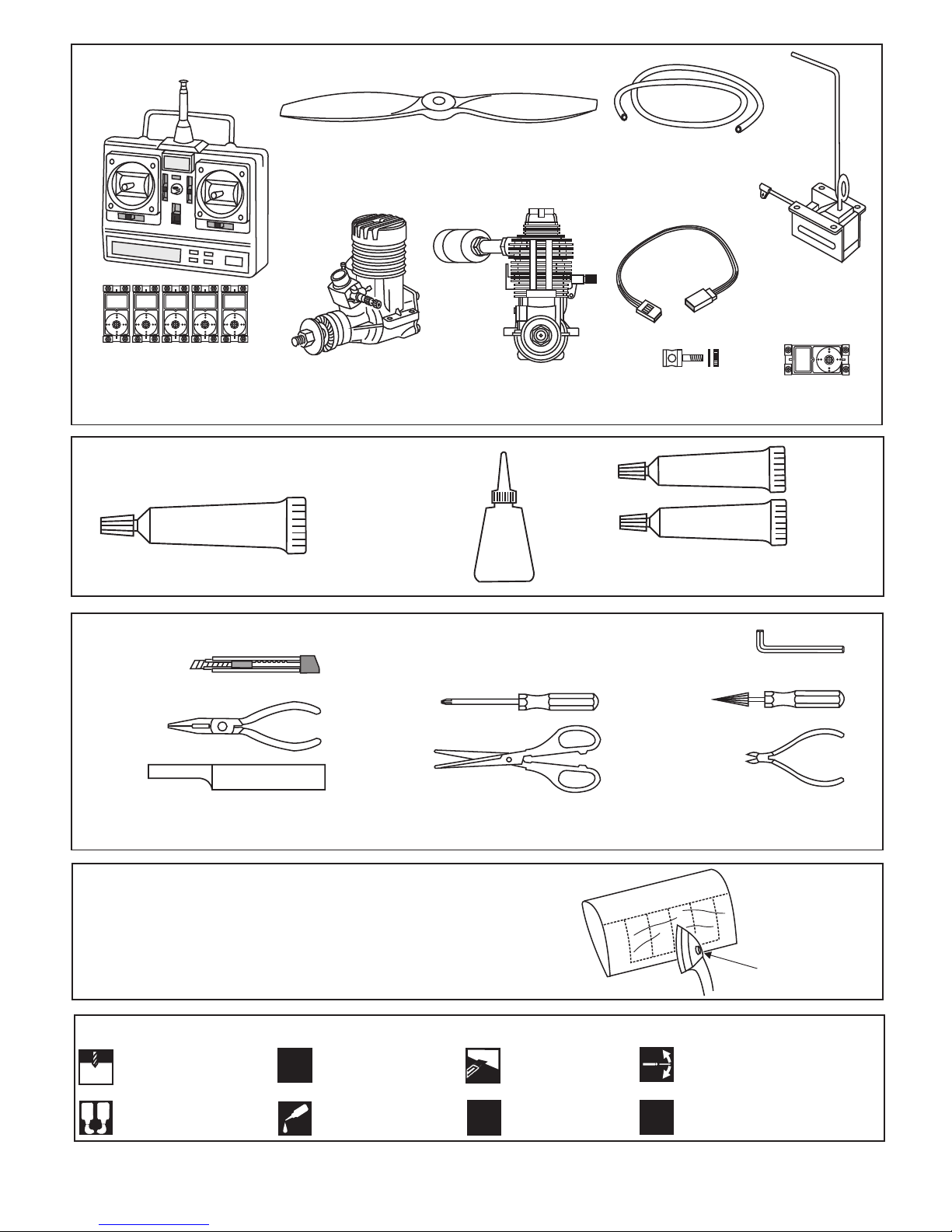
Minimum 5 channel radio
for airplane with 5 servos
.60 ~.70 - 4 cycle
10.5x6 for .40 - 2 cycle engine
11x6 for .46 - 2 cycle engine
12x6 for .60 - 4 cycle engine
12x7 for .70 - 4 cycle engine
Silicone tube
Extension for aileron
servo, retract servo
and power pack
.46 ~ .50 - 2 cycle
REQUIRED FOR OPERATION (Purchase separately)
Linkage Stopper x2
(for retract servo)
Epoxy Glue (30 minute type)
Masking tape - Straight Edged Ruler - Pen or pencil - Rubbing alcohol - Drill and Assorted Drill Bits
Read through the manual before you begin, so you will have an overall idea of what to do.
Symbols used throughout this instruction manual, comprise:
(Purchase separately)
Retract landing
gear
VQAR04 - 160224
Retract servo
x1
.Motor control x1 .Aileron x2
.Elevator x1 .Rudder x1
L/R
2mm
3x12mm screw
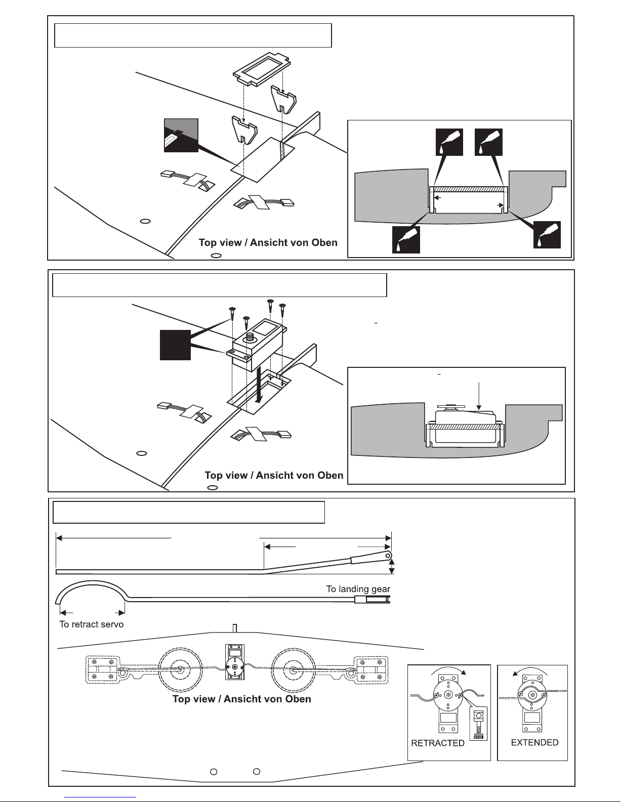
Trial fit the push rod into the wing. Join the pushrod to the retract
gear arm and trial fit the retract into the wing.
After checking that the retract works smoothly, fix the retract on the
wing with 3x12mm screws
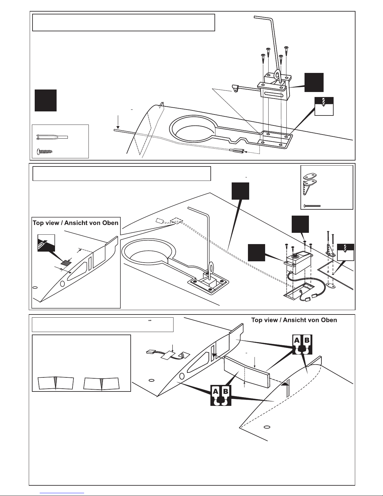
1- Using a pencil, mark the center of the brace.
2- Trial fit the wing joiner into one of the wing panels. It should
insert smoothly up to the center line marked above.
3- Slide the other wing half onto the dihedral brace until
the wing panel meet. If the fit is over tight, it may be
necessary to lightly sand the dihedral brace.
4- Check for the correct dihedral angle.
5- Mix approximately 30 minute epoxy and apply a generous amount of epoxy into the wing joiner cavity of one wing half.
6- Coat one half of the dihedral brace with epoxy up to the center line. Install the epoxy-coated side of the dihedral brace
into the wing joiner cavity up to the center line, marking sure that the “V” of the dihedral brace is positioned correctly
7- Do the same way with the other wing half.
8- Carefully slide the wing halves together, ensuring that they are accurately aligned. Firmly press the two halves
together, allowing the excess epoxy to run out. Clear off the excess epoxy.
Center line
X
Aileron servo
X
Included with the
radio set
Plastic control horn
....................2
2x20mm screw
...............4
2mm
Aileron extension cord
X
Secure one end of the aileron
extension cord with adhesive tape
Querruder servo
Nehmen Sie Epoxykleber, um die
Tragflachen fest miteinander zu Verbinden
und streifen Sie den herausquellenden
Kleber nach dem Verbinden mit einem
fusselfreien Tuch SOFORT ab!
1- Retract landing gear / Fahwerk
2- Aileron servo / Querruder servo
3- Joining the wing / Flache
Use epoxy glue to bury the opening
Retract pushrod
3x12mm schraube
Servoverlangerungskabel
Ansicht von unten
Bottom view
Ansicht von unten
Bottom view /
3x12mm screw
................8
Steel clevis
.........2
40mm
15mm
Fahrwerkanlenkgestange
Wing joiner
Tragflachenverbinde
X
5- Retract servo / Einziehfahrwerk servo
CENTER
WING
SECTION
BOTTOM
Retract servo
/ Retract servo
X
Link the servo and retract gear arm with push rod. Be sure to adjust the stroke so
that the landing gear locks in both up and down position.
2” (~50mm)
1”(25mm)
19/64”
(7.5mm)
8-5/16”(~210mm)
RETRACT PUSHROD (SIDE VIEW)
With the retract and retract servo in the retracted position, mark the position where
each of the pushrod will attach to the servo arm, a small piece of masking tape
works well for this. Cut off the excess length each rod.
(TOP VIEW)
Cut away only
the covering
4- Servo mount / Servohalterung
A
FWU2
FWU1
A
CENTER
WING
SECTION
CA
CA
CA
CA
BOTTOM
Retract servo mount (plywood A,B,C)
Install the retract servo onto the retract
servo mount and secure it in place with
four screw (included with radio set).
Einbau des Servos fur
das Einziehfahrwerk
Instruction how to build in the retracting landing gear
(This Gearis OPTIONAL )
Einbauhilfe bei Anbringen eines
Einziehfahrwerks (Optional
bestellbar; nicht im Baukasten
enthalten!)
Einbau des Servos fur
das Einziehfahrwerk
6- Linkages / Ruderanlenkung
Fahrwerkanlenkgestänge
EINGEFAHREN
AUSGEFAHREN
Einziehfahrwerk servohalterung
Schneiden Sie etwas
Folie weg
FWU2
FWU1
 Loading...