

VQ AICHI D3A1 VAL VQA138 GREEN, AICHI D3A1 VAL VQA138 GRAY Instruction Manual
SPECIFICATIONS
Wingspan:......................................1540mm
Length:...........................................1120mm
Electric Motor:.....................See next pager
Glow Engine:.................... .46 2-T / .70 4-T
Radio:....................6 Channel / 8-9 Servos
Function: Ailerons-Elevator-Rudder-Throttle
Flaps.
WARNING! This radio controlled model is NOT a toy. If modified or flown carelessly it could go out of controll and
cause serious human injury or property damage. Before flying your airplane, ensure the air field is spacious enough.
Always fly it outdoors in safe areas and seek professional advice if you are unexperienced.
ACHTUNG! Dieses ferngesteuerte Modell ist KEIN Spielzeug! Es ist für fortgeschrittene Modellflugpiloten bestimmt,
die ausreichende Erfahrung im Umgang mit derartigen Modellen besitzen. Bei unsachgemässer Verwendung kann
hoher Personen- und/oder Sachschaden entstehen. Fragen Sie in einem Modellbauverein in Ihrer Nähe um
professionelle Unterstätzung, wenn Sie Hilfe im Bau und Betrieb benötigen. Der Zusammenbau dieses Modells ist
durch die vielen Abbildungen selbsterklärend und ist für fortgeschrittene, erfahrene Modellbauer bestimmt.
Radio control model / Flugmodel
ALL BALSA, PLYWOOD CONSTRUCTION AND ALMOST READY TO FLY
JAPANESE DIVE BOMBER
Instruction manual / Montageanleitung
TECHNISCHE DATEN
Spannweite:...................................1540mm
Lange:............................................1120mm
Elektroantrieb.............(siehe nächste Seite)
Verbrennerantrieb:...............7.45cc - 11.5cc
Fluggewicht:.......................................3.5Kg
Fernsteuerung..........6 Kanal / 8-9 Servos
VQ No: VQA138 GREEN
AICHI D3A1 “VAL”
RTF Weight: 3.5Kg (will vary with equipment
use)
VQ No: VQA138 GRAY
1.5mm
A
B
!
CA
L/R
Assemble left and right
sides the same way.
X
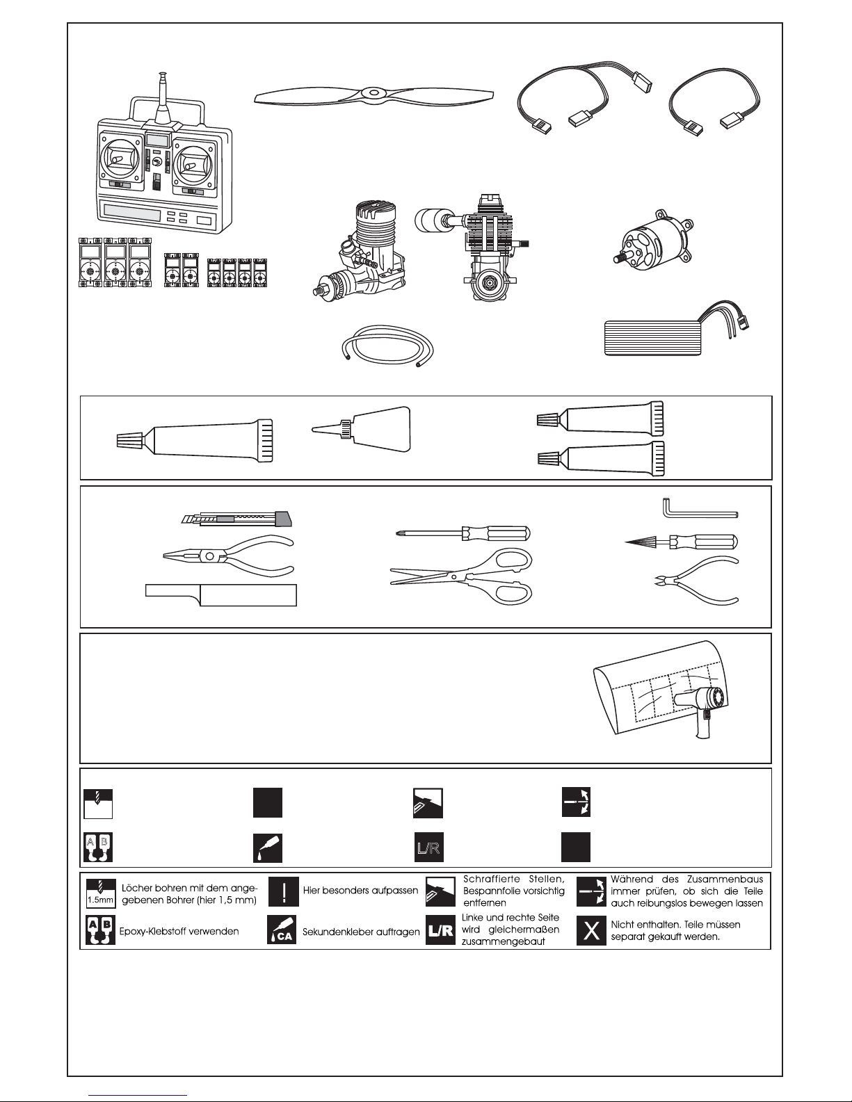
Drill holes using the stated
size of drill
(in this case 1.5 mm )
Use epoxy glue
Take particular care here
Hatched-in areas:
remove covering
film carefully
Not included.
These parts must be
purchased separately
Check during assembly that these
parts move freely, without binding
Apply cyano glue
SILICON
CA
GLUE
Silicon sealer
Cyanoacrylate Glue (thin type)
Minimum 6 channel radio
.60 ~.70 - 4 cycle
10.5x6 for .40 - 2 cycle engine
11x6 for .46 - 2 cycle engine
12x6 for .60 - 4 cycle engine
12x7 for .70 - 4 cycle engine
13x7 - 13x8 for electric motor
Silicone tube
Aileron: 50cmx2 pcs
.46 ~ .50 - 2 cycle
TOLLS REQUIRED
Hobby knife
Needle nose Pliers
Phillip screw driver
Awl
Scissors
Wire Cutters
(Purchase separately)
Hex Wrench
.........................................................
.........................................................
.........................................................
.........................................................
.........................................................
.........................................................
.........................................................
.........................................................
.........................................................
.........................................................
.........................................................
Sander
Masking tape - Straight Edged Ruler - Pen or pencil - Drill and Assorted Drill Bits
Read through the manual before you begin, so you will have an overall idea of what to do.
Symbols used throughout this instruction manual, comprise:
(Purchase separately)
CONVERSION TABLE
1.0mm = 3/64”
1.5mm = 1/16”
2.0mm = 5/64”
2.5mm = 3/32”
3.0mm = 1/8”
4.0mm = 5/32”
5.0mm = 13/64”
6.0mm = 15/64”
10mm = 13/32”
12mm = 15/32”
15mm = 19/32”
20mm = 51/64”
25mm = 1”
30mm = 1-3/16”
45mm = 1-51/64”
If exposed to direct sunlight and/or heat, wrinkels can appear. Storing the
model in a cool place will let the wrinkles disappear. Otherwise, remove
wrinkles in covering film with a hair dryer, starting with
low temperature. You can fix the corners by using a hot iron.
Bei Sonneneinstrahlung und/oder Wärme kann die Folie erschlaffen bzw. Falten
entstehen. Verwenden Sie ein Warumluftgebläse (Haartrockner) um evtl. Falten aus der Folie
zu bekommen. Die Kanten können Sie mit einem Bügeleisen behandeln. Nicht zuviel Hitze anwenden !
REQUIRED FOR OPERATION (Purchase separately)
Low seting
700-800W Brushless Motor
5 cell 4500mAh LiPo battery
Rx battery pack: 20cmx1 pcs
EPOXY A
EPOXY B
Epoxy Glue
(30 minute type)
Standard
Mini
Micro
Elevator : 1 standard servo
Rudder: 1 standard servo
Aileron: 2 mini servo
Flaps: 4 micro servo
Throttle: 1 standar servo (for glow engine only)
Flap: “Y” x2 pcs
Aileron: “Y”x1pcs
Flap: 30cmx2 pcs
FRONT-VIEW
A
B
B’
A
B=B’
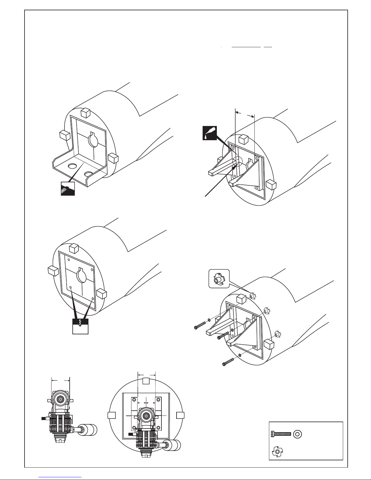
Cut the wood along the line as shown
(1A) in case of 4T engine using
! Align the mark on both engine mount
beams with the mark on the fuselage
Attach the engine mount beams onto the fire-wall
so the distance between of two engine mount beams
is “A”,and B=B’ as show.
Secure the engine mount beams onto the fire-wall
with litter CA glue (1B)
Using a pencil or felt tipped pen, mark
the fire wall where the four holes are to
be drilled(1B))
Carefully remove the engine mount beams
and drill a 6mm hole through the fire-wall
at each of the four marks made above (1C)
6mm
A
Reposition the engine mount beams on to the fire-wall
and secure them with four 4x25mm screw (1D)
...................4
....................4
4x25mm screw - washer
Blind-nut
Insert the blind-nut onto each
of the four holes make above (1D).
! Align the mark on both
engine mount beams with
the mark on the fire-wall.
Push left (or right) the magnetic fuel tank hatch
and full it out of the fuselage.
1- ENGINE MOUNT
1A
CA
1B
1C
1D
1D
! Engine thrust on balk head
is already adjust at factory
SIDE-VIEW
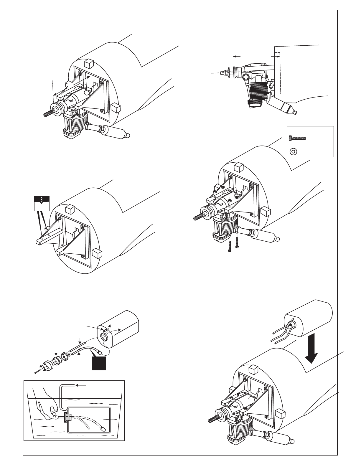
122-124mm
FUSELAGE
Position the engine to the engine mounts so the distance from the prop hub
to the fire-wall is 122 - 124mm.
Mark the engine mounting plate where the four holes are to be drilled (2A)
Remove the engine and drill a 3mm holes through the beam at each
of the four marks made above (2B)
Reposition the engine on the engine mount
beams, aligning it with the holes. Secure the
engine to the engine mount using four
3x25mm screws (2C)
Note: Apply Silicon sealer to each of the
3x25mm screw and nut.
.......4
3x25mm screw
Washer
.......4
C=122-124mm
Marking sure that you drill the hole perpendicular to the beam of the
engine mount.
3mm
X
To muffler
Filler tube
To engine
3x35mm screw
Rubber stopper
Checking for leaks - block the vents
and blow into the feed - if in doubt
submersing the tank in a blow of
water will show up any problems.
Blow
Water
Carefully install the fuel tank
to ensure that they will not
shift during flight (2F).
2- ENGINE
2A
2B
2C
2D
2E
2F
C
B=B’
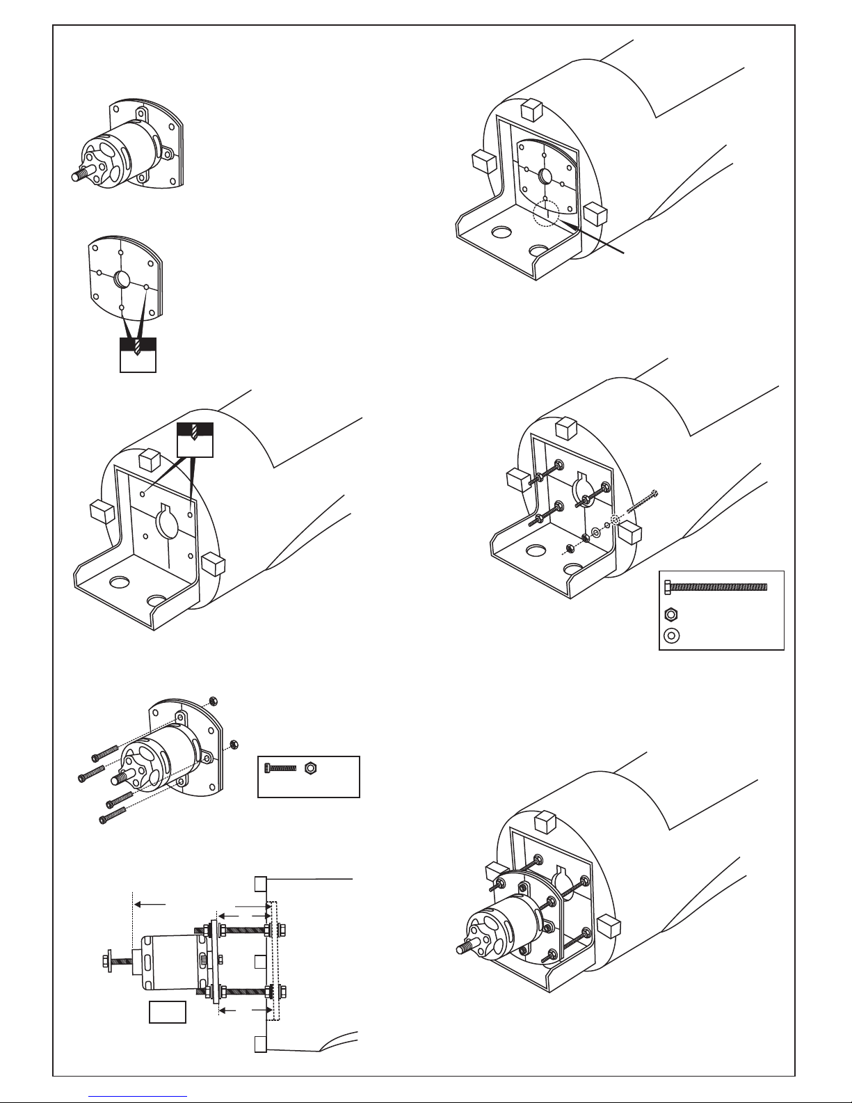
! Motor thrust on balk head
is already adjust at factory
Using a wooden motor mounting plate as a template,
mark the fire-wall where the four holes are to be drilled (3C).
Remove the wooden motor mounting
plate and drill a 6mm hole through
the fire-wall at each of the four marks
marked (3D) .
SIDE-VIEW / Seitenansicht
Using a aluminum motor mounting plate
as a template, mark the plywood motor
mounting plate where the four holes are
to be drilled.
Remove the aluminum motor mounting
plate and drill a 1/8”(3mm) hole through
the plywood at each of the four marks
marked .
3mm
B’
B
FUSELAGE
122-124mm
Attach the four 5x70mm bolts
and nuts to the fire-wall as
shown (3E).
3mm bolt / nut...4
Secure the Motor to the wooden
motor mounting plate using the
four 3mm bolts.
3- ELECTRIC MOTOR
3A
3B
3C
! Align the mark on wooden motor
mounting plate with the mark on
the fire-wall.
3D
3E
3F
3G
6mm
6x100mm bolt.....4
6mm nut..........12
6mm washer...16
2x6mm self tapping
screw
..........8
....2
...2
4mm collar
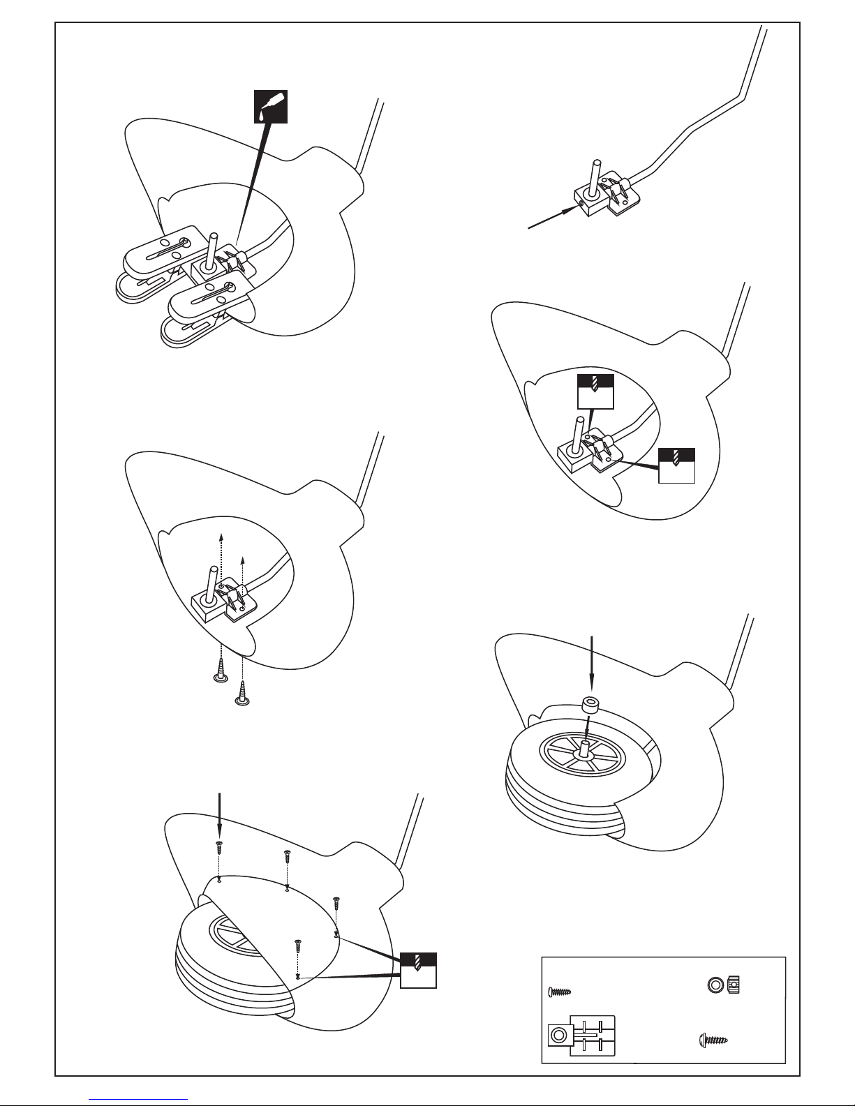
Wheel pant mount
Secure the wheel pant
mount in place using the
3mm screw set.
CA
1.5mm
1.5mm
1.5mm
Slide the wheel pant mount
onto the landing gear
4- WHEEL PANT
4A
4B
Slide the landing gear with the wheel pant into the
fiber glass wheel pant and secure it in place using
the two clothespin and litter thin CA glue as shown (4B).
4C
Remove the clothespin and drill the two 1.5mm holes
as shown (4C).
2.5x10mm
self tapping screw
2x6mm self tapping screw
2.5x10mm self
tapping screw
..........4
4mm collar
4D
4E
4F
 Loading...