

Page 1

Quick Start Guide
Vpacket 5100/6100 Voice/Data Router
SDSL WAN model
Release 2.1.1
Page 2

Trademarks and copyrights
All trademarks and registered trademarks listed belong to their respective owners.
Vpacket, Vpacket Communications, and the Vpacket 5100/6100 Series Voice/Data Router are registered trademarks of
Vpacket Communications, Inc., Milpitas, California.
Vpacket Communications, Inc. does not warrant that the hardware will work properly in all environments and applications,
and makes no warranty and representation, either implied or expressed, with respect to the quality, performance,
merchantability, or fitness for a particular purpose.
The products and programs described in this document are licensed products of Vpacket Communications, Inc. This
document contains proprietary information protected by copyright, and this document and all accompanying hardware,
software, and documentation are copyrighted. Vpacket Communications, Inc. has made every effort to ensure that this
manual is accurate. However, information in this guide is subject to change without notice and does not represent a
commitment on the part of Vpacket Communications, Inc. Vpacket Communications, Inc. makes no commitment to
update or keep current the information in this document, and reserves the right to make changes to this manual and/or
product without notice. Vpacket Communications, Inc. assumes no responsibility for any inaccuracies and omissions that
may be contained in this document. If you find information in this document that is incorrect, misleading, or incomplete,
we would appreciate your comments and suggestions.
No part of this document may be reproduced or transmitted in any form or by any means, electronic or mechanical,
including photocopying, recording, or information storage and retrieval systems, for any purpose other than the purchaser's
personal use, without the express written permission of Vpacket Communications, Inc.
Copyright © 2002 by Vpacket Communications, Inc.™ U.S. Patents Pending. All Rights Reserved. Reproduction or media
conversion by any means is protected by copyright and may only occur with prior written permission of Vpacket
Communi
cations, Inc.
The PSQM technology included in this product is protected by copyright and by European, US, and other patents, and is
provided under license from OPTICOM Dipl. Ing. M. Keyhl GmbH, Erlangen, Germany, 2002
Document title Date issued
Vpacket Series 5100/6100 Voice/Data Router Quick Start
Guide SDSL WAN model
June 2002 750-0030-001, Rev C
Product number Release
2.1.1
SDSL
2 Vpacket 5100/6100 Series QuickStart Guide SDSL
Page 3

About this guide
This guide is intended for experienced users and is designed to facilitate the installation and
configuration of a Vpacket 5100/6100 Voice/Data Router (VDR) that has a SDSL WAN interface.
For detailed installation information, refer to the Vpacket 5100/6100 Voice/Data Router Installer’s Guide
(P/N 750-0024-001, Rev A) or the Vpacket 5100/6100 Voice/Data Router Reference Manual, which is
divided into the following sections:
• Vpacket 5100/6100 Series Voice/Data Router Reference Manual (Data Features)
• Vpacket 5100/6100 Series Voice/Data Router MGCP Telephony Configuration
• Vpacket 5100/6100 Series Voice/Data Router SIP Telephony Configuration
• Vpacket 5100/6100 Series Voice/Data Router H.323 Telephony Configuration
This related documentation is located on the CD-ROM that is shipped with this product.
What’s in the box?
The following items are shipped with a Vpacket 5100/6100 VDR.
About this guide
❑ Vpacket 5100/6100 VDR ❑ self-adhesive rubber feet (4)
❑ AC power cord ❑ wall mount brackets (2)
❑ male DB9 to female DB9 cord ❑ Release Notes 2.1.0
❑ RJ45 straight-through cable ❑ Quick Start Guide 2.1.0 (SDSL WAN)
❑ rack mount brackets (2) ❑ Product documentation CD-ROM
If any of the items listed above are missing or defective, contact Vpacket Communications, Inc. at
(866) 872-2538.
Additional tools, materials, and cables
The following additional tools are required to install the 5100/6100 VDR:
• A flathead screwdriver and a Phillips screwdriver for securing the cables
• A 1/4" hex nutdriver to secure the captive grounding nut on the back panel
• Screws for installation in a 19" equipment rack
Vpacket 5100/6100 Series QuickStart Guide SDSL 3
Page 4
Installation site
M
3
The following additional cables and wire are required to install the 5100/6100 VDR with other
internetworking equipment:
• serial cable (DB-9 male to DB-25 female)
• straight-through cable (RJ-45 with boot cover)
• grounding wire
Installation site
Vpacket 5100/6100 VDRs are designed to be installed on a wall, within a standard 19-inch (48.26 cm)
rack, or on a desktop. You should observe these guidelines:
• Ensure that the side of the unit with the fans (right-hand side panel if you are facing the unit
from head-on) is not placed in the top-most position; this would defeat the air-flow and
encourage overheating.
• Collocate the punchdown panel and voice ports.
• Ensure sufficient clearance for airflow and cable routing. The LEDs on the front panel should be
easily visible and cables to the connectors on the back panel should be easily accessible.
• Ensure that the indoor room temperature does not exceed 50°C (122°F).
• Maintain the 5100/6100 VDR by keeping the unit clean and free of dust and other
contaminating particles before, during, and after installation.
Connections
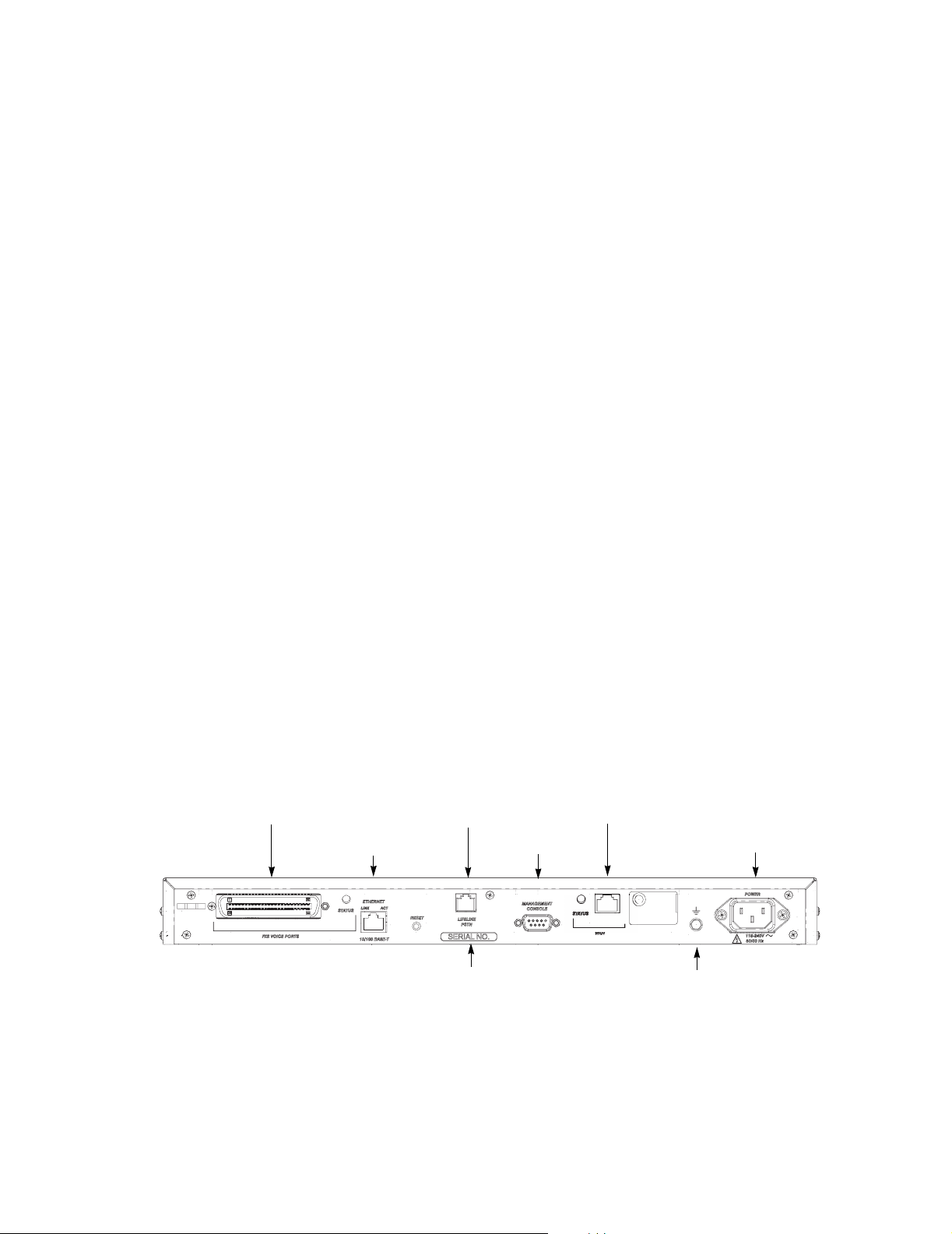
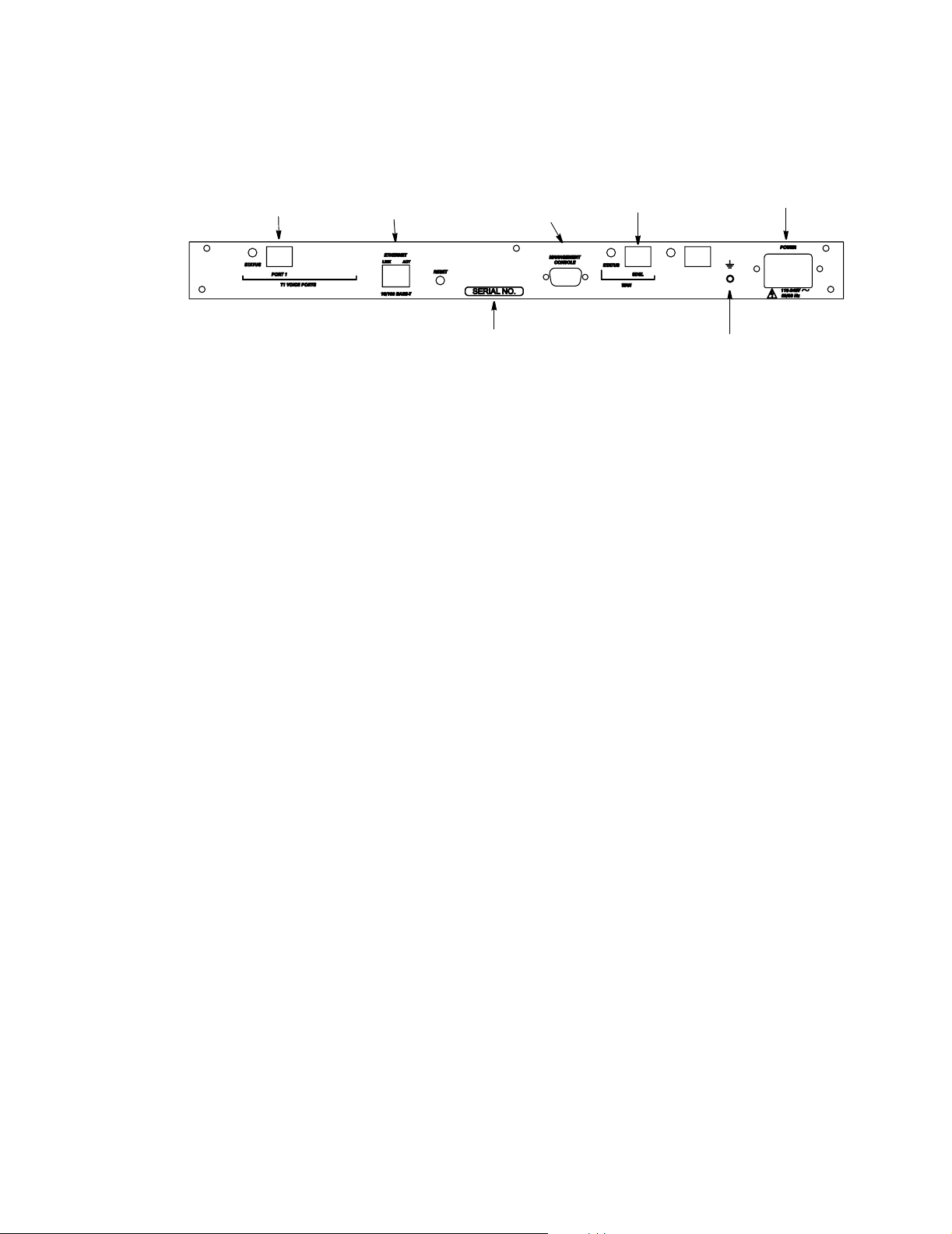
These diagrams show the back panel of an SDSL WAN 5100/6100 VDR with an FXS interface and
a T1-CAS interface. You can see the various ports and cables that this models accept. The serial
number location and grounding nut are also shown.
FXS interface accepts a
female Amphenol 50-pin cable
FXS voice and SDSL WAN model 5100/6100
Ethernet port accepts a
Cat 3 or 5 UTP cable
12 & 24 Port FXS VIM +T1 WI
PSTN port accepts
standard telephone cable
Serial number
Serial port accepts
a male DB9 to female DB9
SDSL port accepts RJ45 cable
810-0102-002 & 810-0102-00
SDSL
AC power cord
Blank
Captive grounding nut
4 Vpacket 5100/6100 Series QuickStart Guide SDSL
Page 5
Powering on the 5100/6100 VDR
T1 port accepts
an RJ45 cable
Ethernet port accepts
Cat 3 or 5 UTP cable
Serial number
T1 voice and SDSL WAN model
Powering on the 5100/6100 VDR
After making the physical port connections, you can connect the power supply cord into the Power
receptacle on the back panel of the 5100/6100 VDR and connect the 3-pronged end of the power
cord into an AC power outlet. The unit powers on automatically when enough power is available.
User interface
To access the command line interface (CLI) through the management console port (located on the
back panel of the unit), you need to connect a terminal or PC that is running emulation software to
the 5100/6100 VDR. After connecting to the management console port, configure the emulation
software as follows:
• Bits per second: 57600 baud
Serial port
Accepts DB9 to female DB9
SDSL port accepts
an RJ45 cable
AC power cord
Captive grounding nut
•Data bits: 8
• Parity: none
• Stop bits: 1
• Flow control: none
If you are connected locally, you can telnet to the default Ethernet IP address (192.168.0.254) to
access the CLI.
Vpacket 5100/6100 Series QuickStart Guide SDSL 5
Page 6

Initial configuration
Initial configuration
You can use the following commands to:
• log in as administrator
• change the system password
• create a user account
• set the system name
• set the system time
• set the date
Logging in
Login:admin
Password:admin
Changing the system password
VPacket# set user modify admin password
Enter the new password :sea_blue456
Reenter the new password :sea_blue456
New password will be used on the next login
Create a user account
VPacket# set user add seashell writedata
Enter the new password :seaweed_987
Reenter the new password :seaweed_987
User name : seashell
Access Level : writedata
Setting unit information
VPacket# set systemInfo systemname Seahorse_north
Seahorse_north#
Setting the time
VPacket# set time 15:48:30
Setting the date
VPacket# set date 06/13/2002
6 Vpacket 5100/6100 Series QuickStart Guide SDSL
Page 7
Interface configuration
w
The LAN, WAN, and voice interface configuration can be accomplished by issuing a combination of
the commands given below. For additional help, enter help+Enter for a list of top-level system
commands. Pressing the spacebar+? after a top-level word lists options within that group of
commands. Bold indicates the command input and bold italics indicate argument input.
Note. For a complete list of arguments for a command, enter the command space ? and the arguments will appear in the order you are required to enter them.
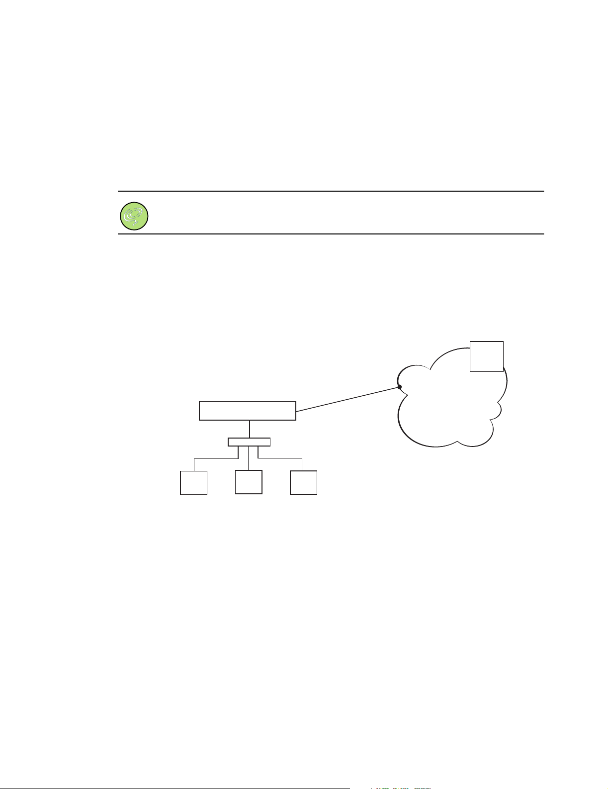
Network diagram
The values in this diagram are used for the interface and telephony configuration examples.
The 6100 VDR has an Ethernet LAN IP address of 15.15.15.254
and is connected to a switch behind which resides the 15.15.15.0
network. The WAN IP address is a public address and connects the
6100 VDR (via a SDSL connection) to a gateway (205.176.94.12)
that connects the network to the Internet. For voice services,
the 6100 VDR communicates with the DSLAM
ith IP address 38.170.77.11.
LAN: 15.15.15.254
6100 VDR
Switch
SDSL
WAN: 205.176.94.11
205.176.94.12
Interface configuration
DSLAM
38.170.77.11
Network cloud
PC host
15.15.15.1
PC host
15.15.15.2
PC host
15.15.15.3
Ethernet LAN interface configuration
VPacket# set ip lan 15.15.15.254 255.255.255.0 NAT
VPacket# set ip gateway 205.176.94.12
VPacket# commit ip
VPacket# save
Vpacket 5100/6100 Series QuickStart Guide SDSL 7
Page 8
Interface configuration
WAN interface configuration
VPacket# set ip wan 205.176.94.11 255.255.255.0
VPacket# set wan loopback noloopback
VPacket# commit ip
VPacket# save
SDSL WAN interface configuration
VPacket# set wan dslam Copper Mountain
Note. The DSLAM type can also be LucentStinger.
VPacket# set wan data protocol funi
Note. The data protocol can be set to funi (to interoperate with a Copper Mountain T1 aggregator) or atm (to interoperate with a Lucent Stinger). When you set the DSLAM type the appropriate choice appears in the help.
VPacket# set wan encap 1483Bridged
Note. The encapsulation protocol can be set to 1483Bridged, 1490Bridged, or 1490Routed.
VPacket# set wan baudrate autobaud
VPacket# set wan dataformat serial
Voice interface configuration
VPacket# set ip voice 205.176.94.11
VPacket# commit ip
VPacket# save
VPacket# reset
8 Vpacket 5100/6100 Series QuickStart Guide SDSL
Page 9

Voice over IP configuration
Vpacket 5100/6100 VDRs support the use of either MGCP, SIP, or H.323 voice stacks for VoIP
support. The telephony commands are accessible through the telephony command shell. To access
the telephony shell, enter tel at the VPacket# prompt. To configure SIP or H.323, see
“Preconfiguration steps for SIP and H.323” on page 11.
MGCP configuration
To configure the 5100/6100 VDR to support MGCP, you need to set each voice port, set the ports to
point to a softswitch (or group of softswitches), set the coding type for each TCID, and set the
coding profile usage for each coding profile.
Note. You can enter telephony commands individually at the prompt or collect them into a text file and copy the settings into the telephony subdirectory for uploading.
Setting the voice ports
VPacket# tel
telephony# set tcid 0 notify_entity 38.170.77.11:2427 dynamic
OK
telephony#
OK
set tcid 1 notify_entity 38.170.77.11:2427 dynamic
Voice over IP configuration
(continue to set voice ports 2-22)
telephony# set tcid 23 notify_entity 38.170.77.11:2427 dynamic
OK
telephony#
OK
telephony#
OK
activate
commit
Vpacket 5100/6100 Series QuickStart Guide SDSL 9
Page 10
Voice over IP configuration
Setting the softswitch identifier
telephony# set tcid 0 endpoint_id a001
OK
telephony#
OK
(continue to set endpoint IDs for TCIDs 2-22)
telephony# set tcid 23 endpoint_id a024
OK
telephony#
OK
telephony#
OK
set tcid 1 endpoint_id a002
activate
commit
Note. Vpacket recommends that you assign them sequentially (see Example). When this command is executed, the endpoint attempts to register with the softswitch. The naming convention (a001...a024) is an example; it is not a VDR standard. The name of the endpoint_id must match that configured in the Call Agent's database.
Setting the coding type
VPacket# tel
telephony# set coding 0 coding_type tx g711_mu
OK
telephony#
OK
(continue to set the coding type for TCIDs 2-22)
telephony# set coding 23 coding_type tx g711_mu
OK
telephony#
OK
telephony#
OK
set coding 1 coding_type tx g711_mu
activate
commit
10 Vpacket 5100/6100 Series QuickStart Guide SDSL
Page 11

Setting the coding usage
telephony# set coding 0 usage voice on
OK
telephony#
OK
set coding 1 usage fax on
(continue to set the usage for TCIDs 2-22)
telephony# set coding 23 usage voice on
OK
telephony#
OK
telephony#
OK
activate
commit
Preconfiguration steps for SIP and H.323
Voice over IP configuration
The 5100/6100 VDR automatically generates a default dial plan upon boot up. This dial plan needs
to be removed along with any existing telephony configuration. Next, you need to create a custom
dial plan and add a hunt group (for H.323 or SIP). View commands for hunt groups and the dial plan
are included in this section. To run SIP with PRI/ISDN section, refer to the supplemental Quick
Start Guide named SIP with PRI/ISDN signaling.
Removing the default telephony configuration
VPacket# tel
telephony# flash clean
nmm_flash_cmd_proc: config file erased
nmm_flash_cmd_proc: ATPM file erased
telephony#
VPacket# reset
Resetting the unit will terminate all calls
Do you want to continue (y|n) [n]?
(After the VDR reboots login again.)
Login:xxxxx
Password:yyyyy
exit
Y
Vpacket 5100/6100 Series QuickStart Guide SDSL 11
Page 12
Voice over IP configuration
Removing the default dial plan
VPacket#tel
telephony# atpm req (Allows configuration changes to be made)
OK
telephony# 01/25/2002:13:14:19 - NMM: ATPM Update Database Granted
telephony#
OK
atpm purge all
Creating a new custom dial plan
Note. The system creates a new custom dial plan that use contiguous numbers starting eith
the first-dn.
Command syntax: atpm sys <dial_time> <1st_digit_wait><inter_digit_wait>
<dial_out_code> <area_code><office_code> <first_dn> [dial_term_digit]
telephony# atpm sys 120000 30000 10000 9 408 581 1225 #
OK
telephony# atpm genlist all
OK
Adding a hunt group
Note. It is necessary to add a hunt group to allow for calls to be placed outside the VDR
with a SIP Server/Proxy or H.323 gateway.
Command syntax:
<member1_id> <member2_id>....
telephony# atpm hadd 25 1 25
OK
atpm hadd <hunt_group_id> <hunt_type>
Ending an ATPM session
telephony# atpm done
OK
telephony# 01/25/2002:13:18:19 - NMM: ATPM Update database done
Saving the configuration changes to Flash
telephony# atpm store
OK
12 Vpacket 5100/6100 Series QuickStart Guide SDSL
Page 13

Voice over IP configuration
Viewing the dial plan
telephony# atpm slist
System Info: Total dial time = 120000ms, First digit wait = 30000ms,
Interdigit wait = 10000ms, Dial term digit = #,
Dial out code = 9, Area Code = 408, Office Code = 581, First DN= 1225
OK
Viewing the dial plan numbers
telephony# atpm alist
Entry Grp_Id Digits Digits strip Address
1225 0 4 4 4 None
1226 1 4 4 4 None
1227 2 4 4 4 None
1228 3 4 4 4 None
Address Hunt Min Max Prefx Prefix
(dial plan numbers continue)
4085811247 22 10 10 10 None
4085811248 23 10 10 10 None
4085811249 24 10 10 10 None
5811225 0 7 7 7 None
5811246 21 7 7 7 None
5811247 22 7 7 7 None
5811248 23 7 7 7 None
5811249 24 7 7 7 None
9 25 8 32 1 None
(dial plan numbers continue)
OK
Viewing hunt groups
telephony# atpm hlist
Hunt group id: 0, Hunt type = 1, Num members = 1, Member ids = 0
Hunt group id: 1, Hunt type = 1, Num members = 1, Member ids = 1
Hunt group id: 2, Hunt type = 1, Num members = 1, Member ids = 2
Hunt group id: 3, Hunt type = 1, Num members = 1, Member ids = 3
(Hunt group id #4-21 appear here)
Hunt group id: 22, Hunt type = 1, Num members = 1, Member ids = 22
Hunt group id: 23, Hunt type = 1, Num members = 1, Member ids = 23
Hunt group id: 24, Hunt type = 1, Num members = 1, Member ids = 24
Hunt group id: 25, Hunt type = 1, Num members = 1, Member ids = 25
OK
Vpacket 5100/6100 Series QuickStart Guide SDSL 13
Page 14
Voice over IP configuration
SIP configuration
After following all of the voice stack preconfiguration steps, you can configure SIP. To configure SIP
you need complete the following steps:
• set the SIP server/proxy destination ID
• configure a hunt group
• set the caller ID name and number fields
Defining a destination ID for the SIP server/proxy
VPacket#tel
telephony# atpm req (Allows configuration changes to be made)
OK
telephony# 01/25/2002:13:14:19 - NMM: ATPM Update Database Granted
telephony#
atpm dadd
Note. Command syntax: atpm dadd <dest_id> tsgm <tcid> atpm dadd <dest_id> dsmc <ccb> atpm dadd <dest_id> ssmu <ctl dest addr> ctl dest addr -> <udp <user addr> <port>< user addr -> +&@host|userinfo@host host -> host name|x.x.x.x
telephony# atpm dadd 25 ssmu udp +&@2.1.1.1
OK
telephony#
OK
telephony# 01/25/2002:13:18:19 - NMM: ATPM Update database done
telephony# atpm store
OK
atpm done
Viewing the destination ID for a SIP endpoint
telephony# atpm dlist
Dest id = 0, Mode = TSGM, TCID = 0
Dest id = 1, Mode = TSGM, TCID = 1
Dest id = 2, Mode = TSGM, TCID = 2
(continues listing destination IDs)
Dest id = 24, Mode = TSGM, TCID = 24
Dest id = 25, Mode = SSMU, Ctl dst = +&@2.1.1.1 call_opt=0x0000
OK
14 Vpacket 5100/6100 Series QuickStart Guide SDSL
Page 15

Voice over IP configuration
Setting the caller ID name and number fields
Note. The caller ID name and number fields are used to match the username to its
corresponding phone number.
set tcid [tcid] cid name
P for private, or O for unavailable> The underscore character “_” represents spaces in a name.
set tcid [tcid] cid number <Caller ID number which can be 1-10 digits in length, P for
private, or O for unavailable>
telephony# set tcid 0 cid name [email protected] (or [email protected])
OK
telephony#
OK
telephony#
01/25/2002:13:20:10 - TSG: 0, Switched CAS, FXS Loop Start
OK
telephony#
OK
set tcid 0 cid number 4085811225
activate
commit
<Caller ID name which can be which can be 1-15 characters in length,
H.323 configuration
To configure the 5100/6100 VDR to support H.323, you need to set the H.323 gatekeeper mode, set
the gatekeeper, set gatekeeper alias, set the coding type for each TCID, and set the coding profile
usage for each TCID.
Note. You can enter telephony commands individually at the prompt or collect them into a text file and copy the settings into the telephony subdirectory for uploading.
Setting the H.323 mode
VPacket# tel
telephony# set h323 gk_mode manual
Don't forget to set h323 gk_addr!
OK
Setting the H.323 gatekeeper
VPacket# tel
telephony# set h323 gk_addr 38.170.77.11
OK
Vpacket 5100/6100 Series QuickStart Guide SDSL 15
Page 16

Voice over IP configuration
Setting the H.323 alias
VPacket# tel
telephony# set h323 alias add H.323 corporate
OK
Setting the coding type
The coding type must be set for each TCID.
VPacket# tel
telephony# set coding 0 coding_type tx g711_mu
OK
(continue to set the coding type for TCIDs 2-22)
telephony# set coding 23 usage voice on
OK
telephony#
OK
telephony#
OK
activate
commit
Setting the coding usage
VPacket# tel
telephony# set coding 1 usage voice on
OK
telephony#
OK
(continue to set the usage for TCIDs 2-22)
telephony# set coding 23 usage voice on
OK
telephony#
OK
telephony#
OK
set coding 0 usage fax on
activate
commit
16 Vpacket 5100/6100 Series QuickStart Guide SDSL
Page 17
Saving configuration changes
You need to commit all system changes and then save to write changes to the Flash memory. You can
use either the commit command to retain all changes or the commit ip command to retain only IP
interface changes. The save command then writes the changes to the Flash memory.
For telephony changes first you need to issue the activate command and then commit command
(from within the telephony shell).
LEDs
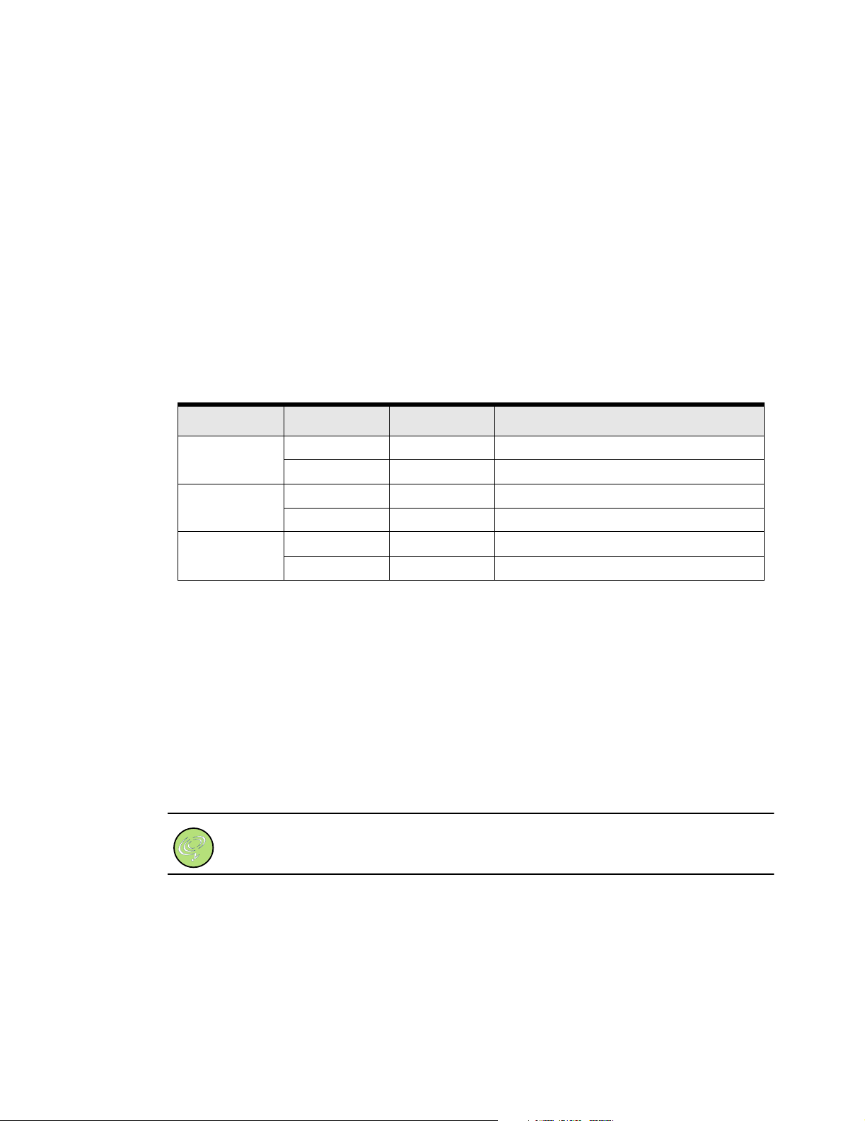
The 5100/6100 VDR has LEDs that indicate real-time conditions. The following table lists the front
panel LED status and management functions
LED Status Color Function
Power Lit Green Normal condition. Unit is receiving power.
Darkened — Unit is not receiving power.
Saving configuration changes
Status Lit Green Normal operation.
Blinking Yellow An error or fault condition exists.
Alarm Darkened — Normal condition.
Blinking Yellow An error or fault condition exists.
Each WAN port has a status LED to the immediate left of the port on the back panel. The single
LAN port has individual LEDs to indicate link status and activity. The FXS and T1 CAS ports have a
status LED to the immediate right of the port.
Upgrading the software image
You can upgrade the current software image by following these steps. First, you will establish a
HyperTerminal or other emulation program session. See “Setting up a HyperTerminal session” on
page 5. Before you begin this procedure, you need to verify connectivity to an FTP server. The
username, password and filename of the code base to be downloaded is required for a successful
upgrade.
Note. Sample values shown for illustration purposes only.
1. Logon to the 5100/6100 VDR.
Vpacket 5100/6100 Series QuickStart Guide SDSL 17
Page 18
Upgrading the software image
2. Issue the show ftp command to display the current FTP settings.
Example:
VPacket# show ftp
-------------------------FTP SETTINGS----------------------
Address of the ftp server : 111.111.111.111
Ftp user name : guest
Ftp user password : guest
Path on the server : C:\
File name to download : SOURCE_CODE.BIN
-----------------------------------------------------------
VPacket#
3. Issue the commands to set the FTP values needed for your installation.
a. Enter the FTP server IP address by issuing the set ftp server command.
Example:
VPacket# set ftp server 10.10.10.3
VPacket#
b. Set the FTP user name by issuing the set ftp user command.
Example:
VPacket# set ftp user vpacket
VPacket#
c. Set the FTP password by issuing the set ftp password command and entering the password
after the command.
Example:
VPacket# set ftp password vpacket
VPacket#
d. Set the FTP path by issuing the set ftp path command and entering the path.
Example:
VPacket# set ftp path C:\
VPacket#
18 Vpacket 5100/6100 Series QuickStart Guide SDSL
Page 19
Upgrading the software image
e. Set the FTP filename by issuing the set ftp filename command and entering the file name.
Example:
VPacket# set ftp filename new_code.bin
VPacket#
4. Change to the maincode directory by issuing the cd maincode command.
Example:
VPacket# cd maincode
Changed to directory maincode
5. When you are in the maincode directory, issue a dir command to discover the code version.
Example:
VPacket# dir
Directory of \maincode
3/ 1/2002 0: 0: 0 <DIR>
3/ 1/2002 0: 0: 0 <DIR>
3/ 1/2002 1:31:50 1262450 OLD_CODE.BIN
3 File(s) 1262450 bytes
Remaining file system bytes: 552448
6. Issue the download image command and enter the filename to start downloading the software
image.
Example:
VPacket# download image new_code.bin
download of new_code.bin to new_code.bin
download# ...................
File new_code.bin successfully downloaded from new_code.bin
VPacket#
Note. You can request that the file be used and active during the next reset by issuing the
download image <filename> requestactive command.
7. Issue dir to verify that the code is now downloaded in \maincode.
8. Reboot the VDR by issuing the reset command from the CLI.
Vpacket 5100/6100 Series QuickStart Guide SDSL 19
Page 20

Upgrading the software image
20 Vpacket 5100/6100 Series QuickStart Guide SDSL
 Loading...