

Page 1
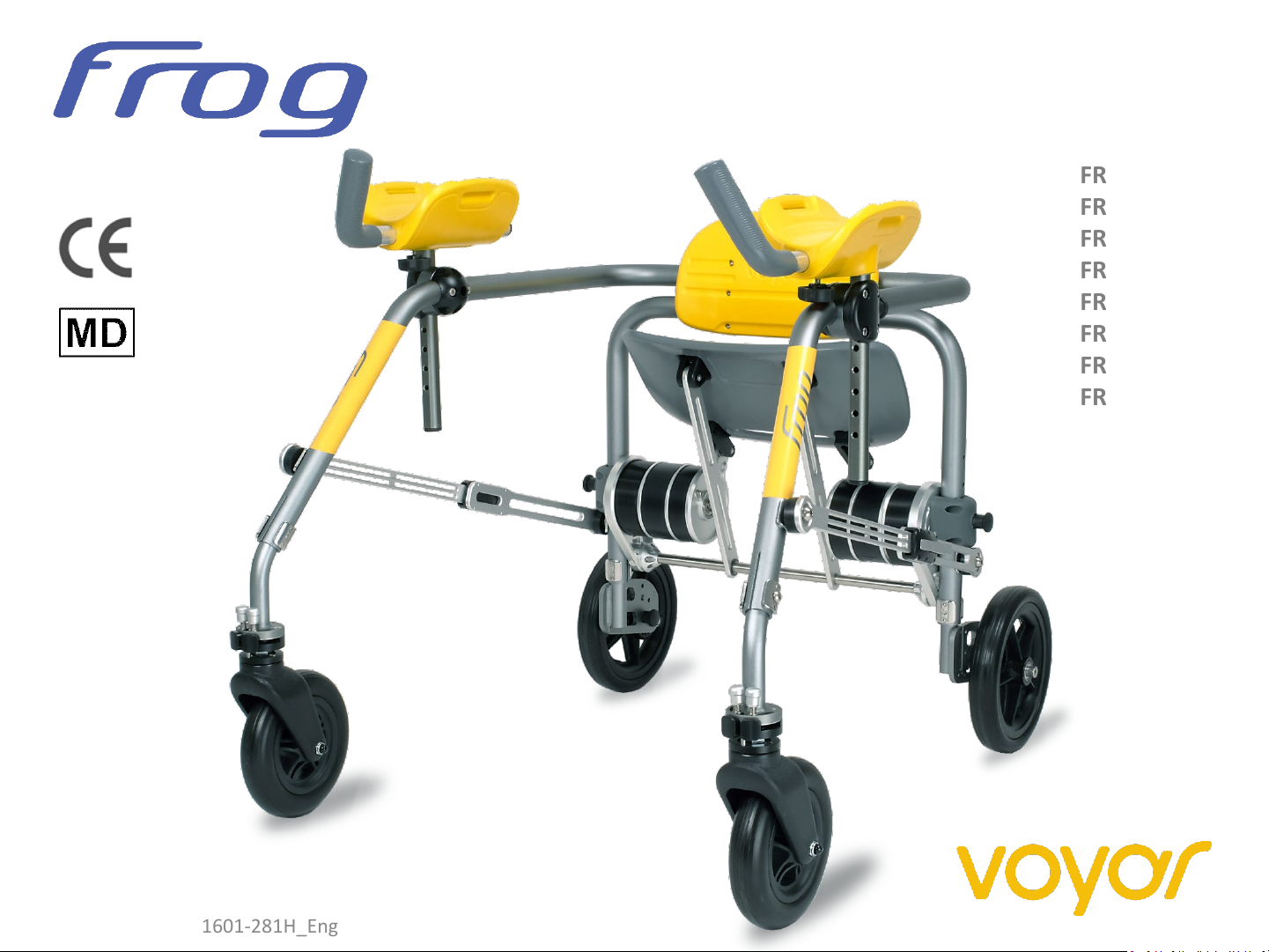
User Manual
FROG M1-X
FROG M2-X
FROG M3-X
FROG M4-X
FROG L1-X
FROG L2-X
FROG L3-X
FROG L4-X
User Manual DP1601-281H_Eng
Page 2

Dear Customer,
Thank you very much for the trust extended in purchasing the Voyar FROG.
Please read the user manual prior to first use of the equipment and follow its instructions.
Could you take care that the user manual remains with the product.
Technical Details are subject to changes.
User Manual DP1601-281H_Eng
Page 3

Contents
Page
1. General Information
1.1. Product Line 5
1.2. Intended Use 6
1.3. Safety Information 7
1.4. Overview of components 8
1.5. Size Adjustments 9
2. Operation
2.1. Therapy Application 10
2.2. Unfolding the walker 11 - 12
2.3. Folding the Walker 13 - 14
2.4. Attaching Arm Supports 15 - 16
2.5. Wheel lock & Anti-reverse 17
3. Lift seat
3.1. Seat Lifting force Adjustment 18 - 21
4. Size adjustments
4.1. Seat Height Adjustment 21 - 23
4.2. Forearm Support Adjustment 24 - 26
4.3. Front Wheel Swivel Limit Setting 27 - 30
4.4. Frame Size Adjustment 31
4.5. Frame Width Adjustment 32
4.6. Frame Height Adjustment 33 - 34
5. Maintenance and Cleaning
5.1. Maintenance 35
5.2. Cleaning 36
5.3. Re-use 37
6. Specifications 38
7. Identification 39
User Manual DP1601-281H_Eng
Page 4
1. General Information
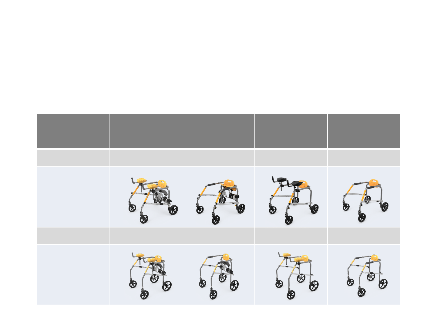
1.1. Product line
This user manual covers the following product variants, which are consisting of medium
size and large frame versions with or without the armrest and seat features:
Frame size With seat and
armrests
Medium FROG M1-X FROG M2-X FROG M3-X FROG M4-X
Large FROG L1-X FROG L2-X FROG L3-X FROG L4-X
With seat
only
With
armrests only
No seat and
armrests
5
Page 5

1.2. Intended Use
The FROG gait trainer provides gait and balance support in patients with walking
difficulties and can be used in the rehabilitation of gait. It has weight bearing handles and
arm rests and a foldable seat as resting position. It can be used indoors in hospitals,
therapy centers and ambulatory activities at home.
6
Page 6

1.3. Safety Information
• The walker should be used indoors and on fairly firm and level ground
• Maximum weight of the user needs to be observed
• Instructions for use should be read carefully before first use. Instructions for use should be kept and
remain with the product for future reference.
• All locks and adjustment knobs on the frame, armrests, seat and wheels need to be checked before
first use and at regular intervals.
• The walking aid should not be used without an accompanying person. Accompanying persons must
be adequately instructed.
• The users should remain within the frame during use.
• Adjustments for handle and the frame width need to remain within the marked maximum limits.
Contraindications :
Users not being able to tolerate an upright position (circulatory issues) or tolerate weight-bearing
(osteogenesis imperfecta, severe osteoporosis, joint instability, severe contractures), as well as
significant lack of head control.
Please report any serious incident that occurred in relation to the device to the manufacturer, XentiQ
Partners Pte Ltd, and to the competent authority of the Member State where the user is established.
7
Page 7
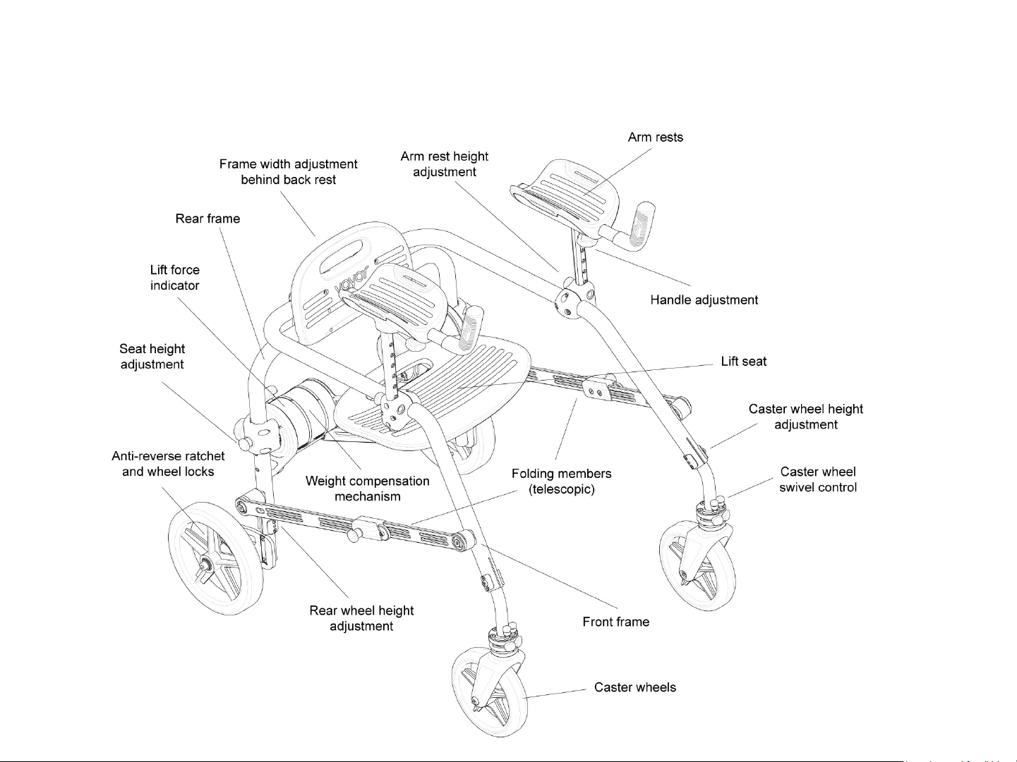
1.4. Overview of components
8
Page 8
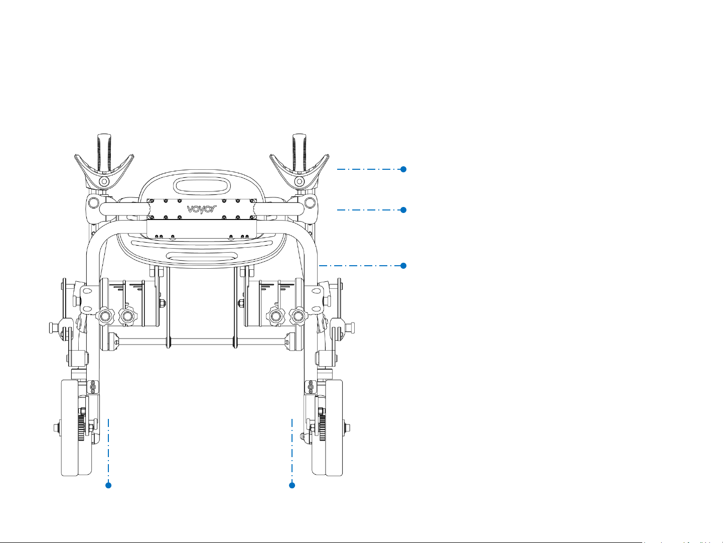
1.5. Size Adjustments
Dimensions for medium size (M) and large size (L) frames
Adjustable armrest height:
M: 62 to 86 cm L: 74 to 95 cm
Adjustable frame height:
M: 52 to 67 cm L: 67 to 76 cm
Adjustable Seat height:
M: 32 to 53 cm L: 49 to 64 cm
Adjustable frame width M: 38 to 46 cm L: 49 to 57 cm
9
Page 9

2. Operation
2.1. Therapy Application
FROG is used to teach children and adolescents who need additional support and stabilization of the upper
body due to disorders of the nervous and muscular system to walk and move independently.
The use of this walking aid during therapy should be supervised by a clinician. The suitability of the device
depending on the degree of the condition should be assessed by a doctor or therapist and settings or
adjustments made in an appropriate manner.
Particular attention should be paid to the position of the user’s feet and, if necessary, the tendancy to cross the
feet. The use of lower leg orthoses is necessary in many cases. Getting in and out of the walker must be done
with the support of the supervisor. The child should grip the handles tightly and place their forearms in the
armrests. If there is insufficient control of the arms they can be stabilized with straps in the armrests.
The supervisor should accompany the user either in front of or behind the walker, paying particular attention
to lateral stability (support with hands if necessary), as well as the position of the feet (avoid crossing).
The initial training takes place step by step, which can be promoted in a playful way (e.g. with a ball). Attention
must be paid to fatigue, whereby regular breaks can be taken using the seat. Folding down and taking the seat
as well as transferring back to standing must be practiced progressively under guidance and can then be done
autonomously in most cases.
10
Page 10
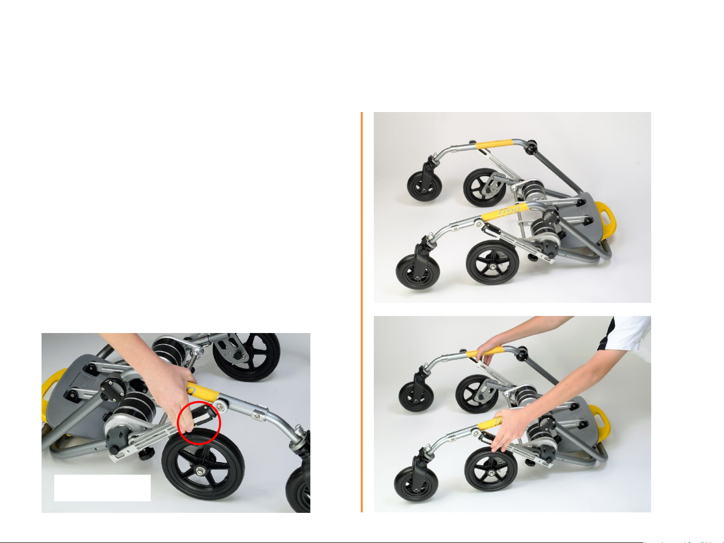
2.2. Unfolding the Walker
The rear wheel of the walker should be
supported on the ground to release the
plunger lock.
1. Push the folding lock lever inwards to
disengage right lock on frame.
Note: There is no need to unlock the left lock for
unfolding.
Unlock
11
Page 11
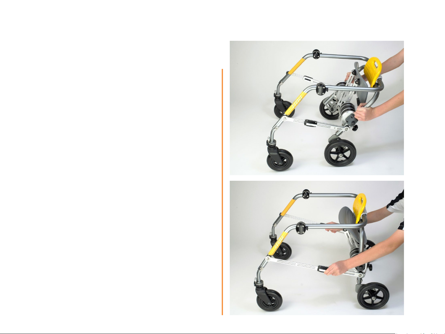
1. Pull back the rear frame against front
wheels on the ground.
2. Once walker is upright, ensure locks on
both sides are ‘engaged’ and in locked
positions.
Caution: Please ensure locks are fully
engaged before use.
12
Page 12
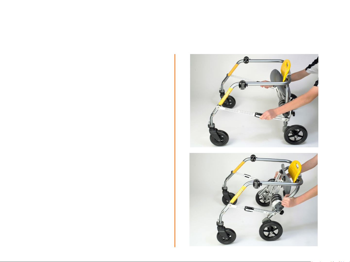
2.3. Folding the Walker
1. Push folding lock levers on both sides of the
links.
2. Holding on to rear frame pull backwards
3. Fold walker until right lock engages to lock
folded position.
13
Page 13
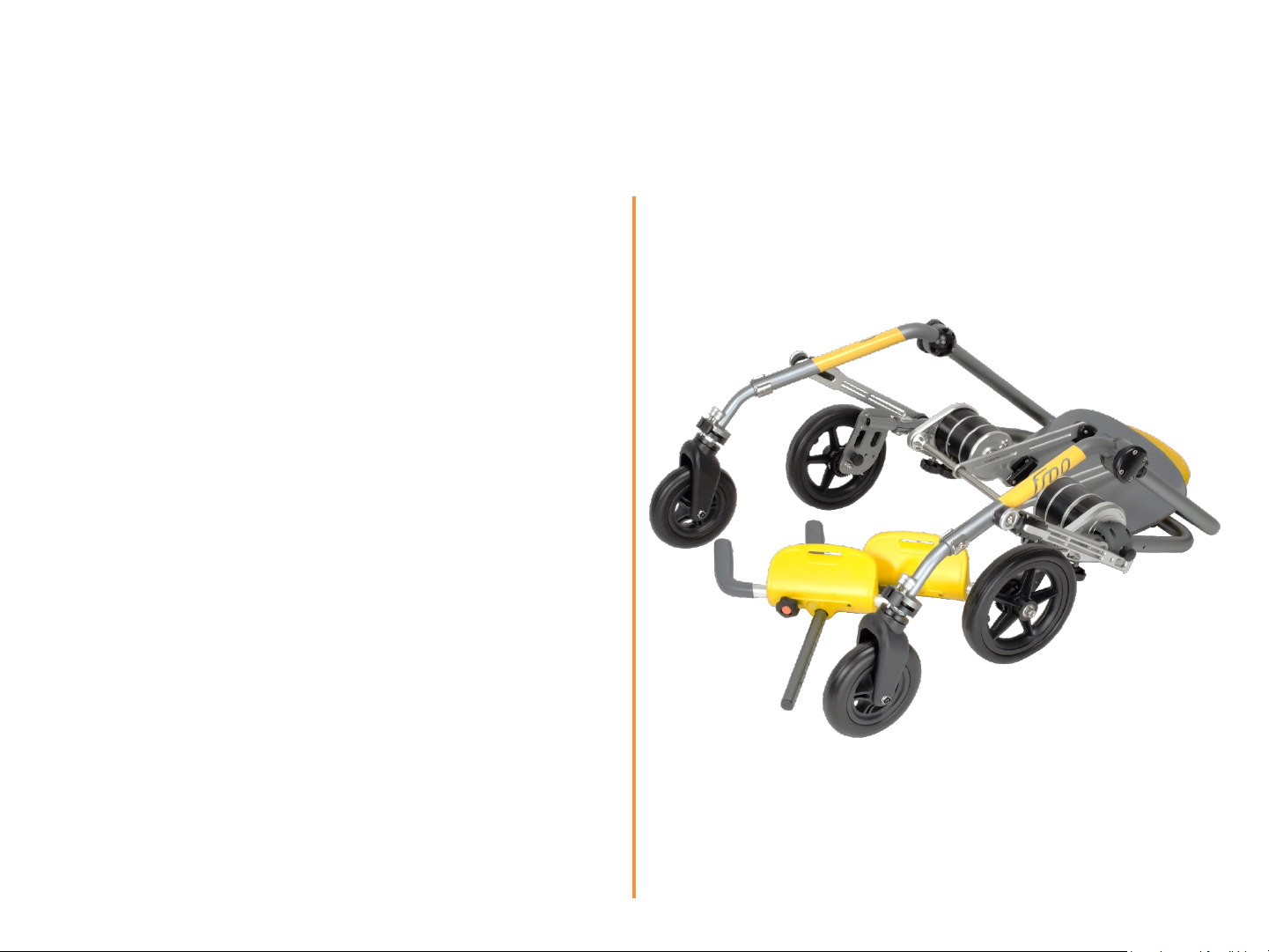
4. Remove both armrests from their sockets
(for models M1-X, M3-X, L1-X and L-3X
with armrests; other models do not have
armrest).
5. The walker is now secured and folded.
14
Page 14
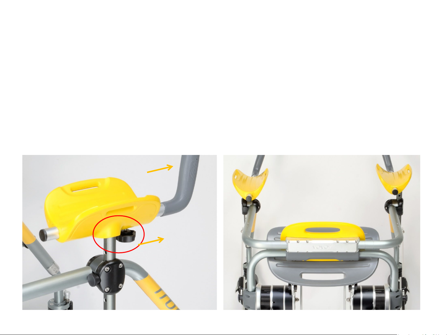
2.4.Attaching Arm Supports
(for models M1-X, M3-X, L1-X and L-3X with armrests; other models do not have armrest).
Each armrest needs to be on the correct side of the walker:
• Take note of section of arm rest that should face outwards (see below circled in red)
• Handle and knob should face forward
• Armrests can only be engaged in holder on correct side
15
Page 15
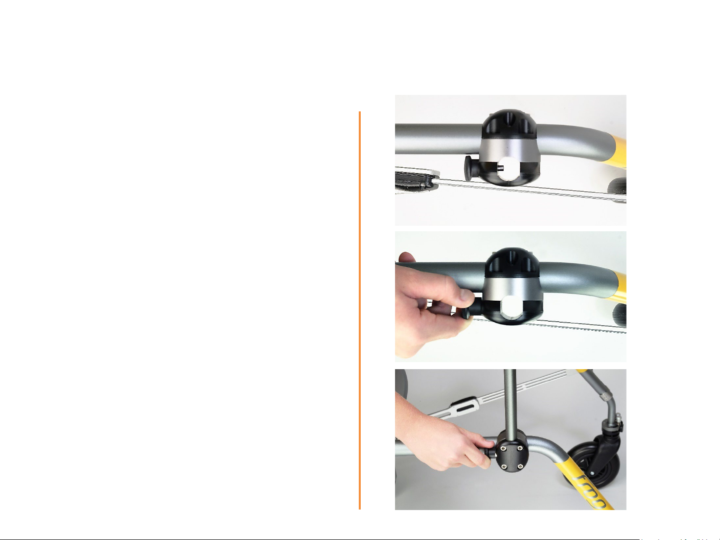
1. Locate the armrest shaft socket.
2. Pull lock out and hold it in position.
3. Holding the aluminium shaft, engage the
arm support into the socket.
4. At desired position, release lock ensuring
pin has engaged with the hole in the shaft. If
not engaged, gently slide the shaft up or
down until lock snaps in.
Refer to page 26 on how to re-adjust
armrest height.
16
Page 16
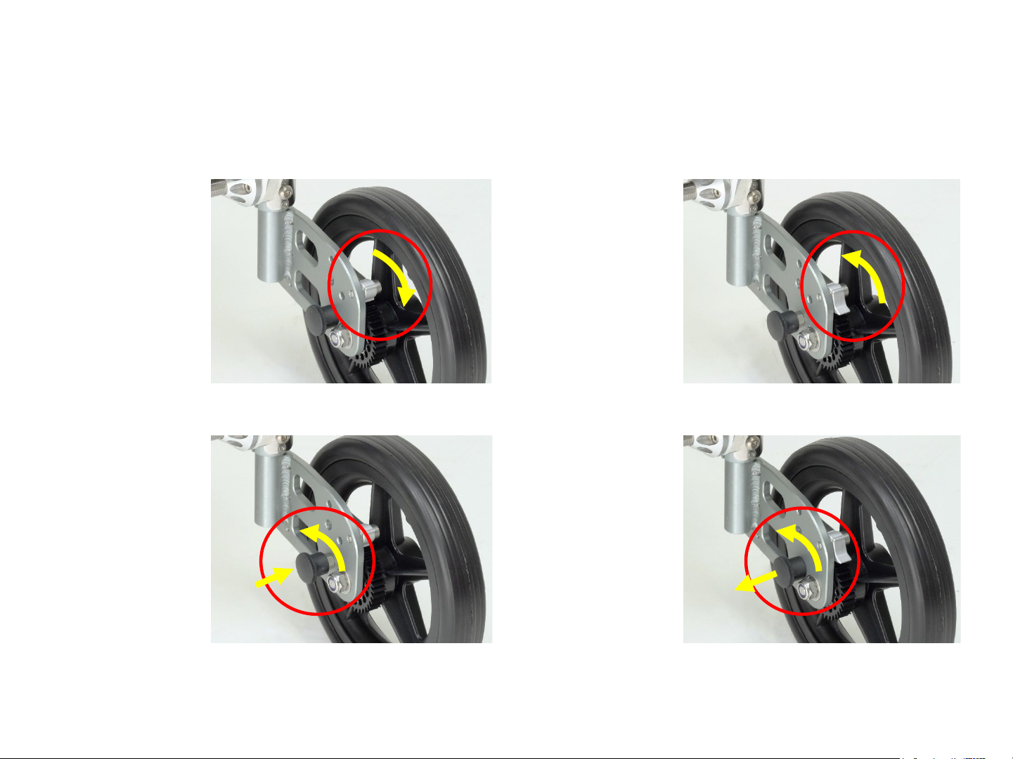
2.5. Wheel lock & Anti-reverse
Each rear wheel has a anti-reverse rachet which can be disengaged:
Anti-reverse
ratchet engaged.
To release, flip tag
towards the rear
Anti-reverse
ratchet released.
To engage, flip tag
towards the front
Each rear wheel can also be locked completely with a spring plunger (“parking brake”)
Wheel lock
released.
To engage,
rotate and
release
Anti-reverse
ratchet engaged.
To release, pull
and turn
The anti-reverse ratchet and the wheel lock are maintenance free. Please verify correct
functioning before initial usage.
17
Page 17
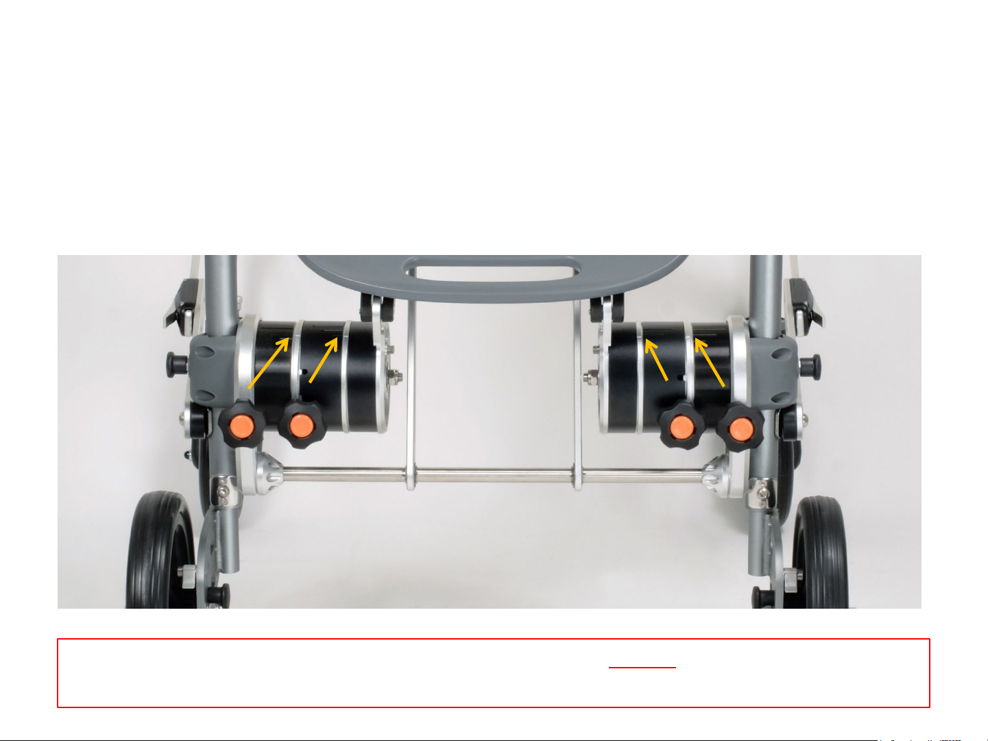
3. Lift seat
(for models M1-X, M2-X, L1-X and L-2X with seat; other models do not have seats).
3.1. Seat Lifting Force Adjustment
Lift force of the seat is controlled by mechanisms located on both the left and right below
the seat. There are two adjustable components for each side - [A] and [B].
[A] [B] [B] [A]
Important: Scales [A] and [B] should be adjusted equally on BOTH sides.
Adjustments should also only be done with seat in flipped up position.
18
Page 18
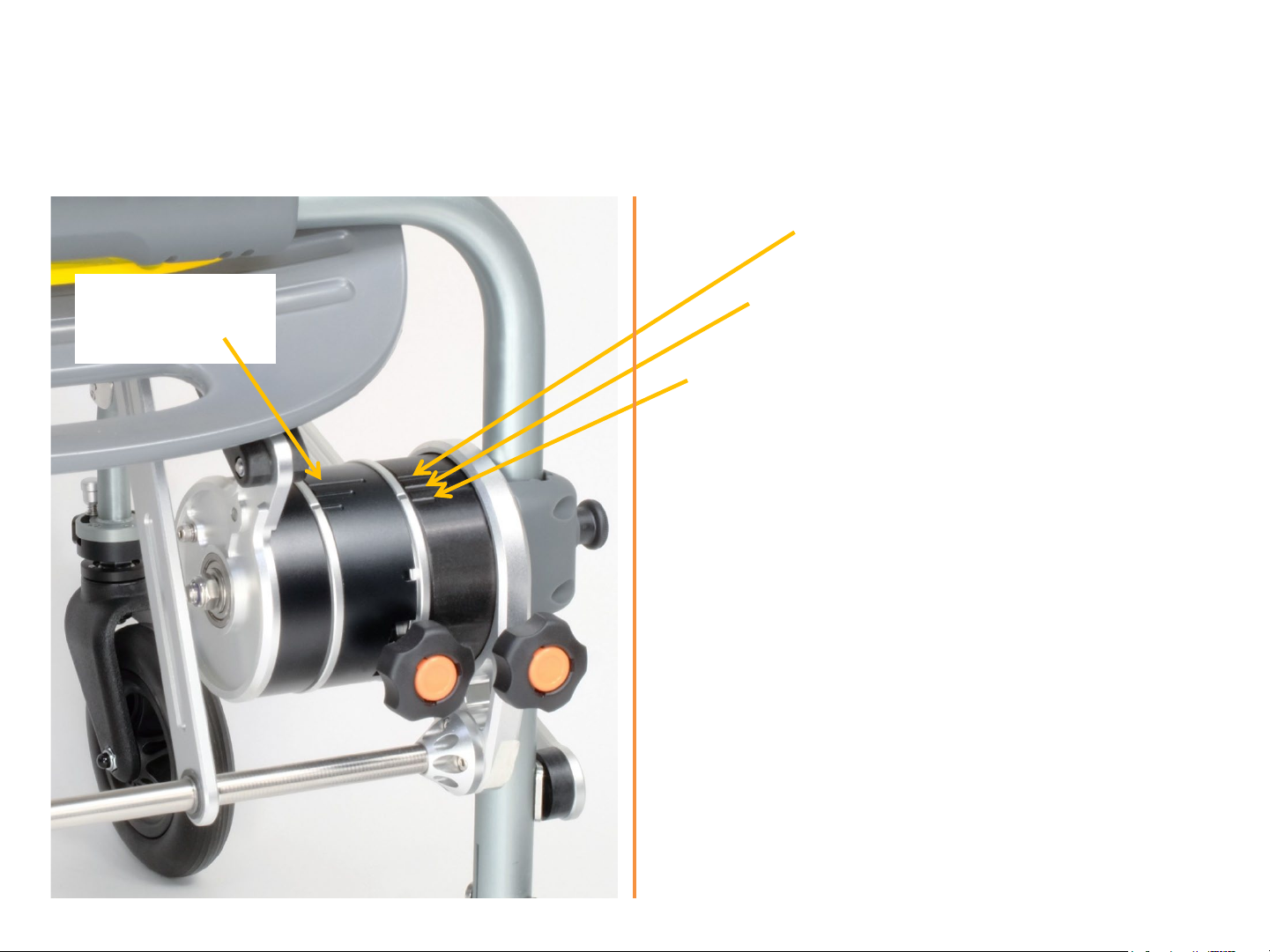
High lifting force
Line marks
on ring
Medium lifting force
Low lifting force
[A] controls the lifting force acting on the user
when in sitting position. The higher the lifting
force, the easier it is to get up.
[B] controls the transition force when the seat is
in half elevated position. Decreasing [B] means it
will be easier to push the seat down in transition.
[A]
[B]
19
Page 19
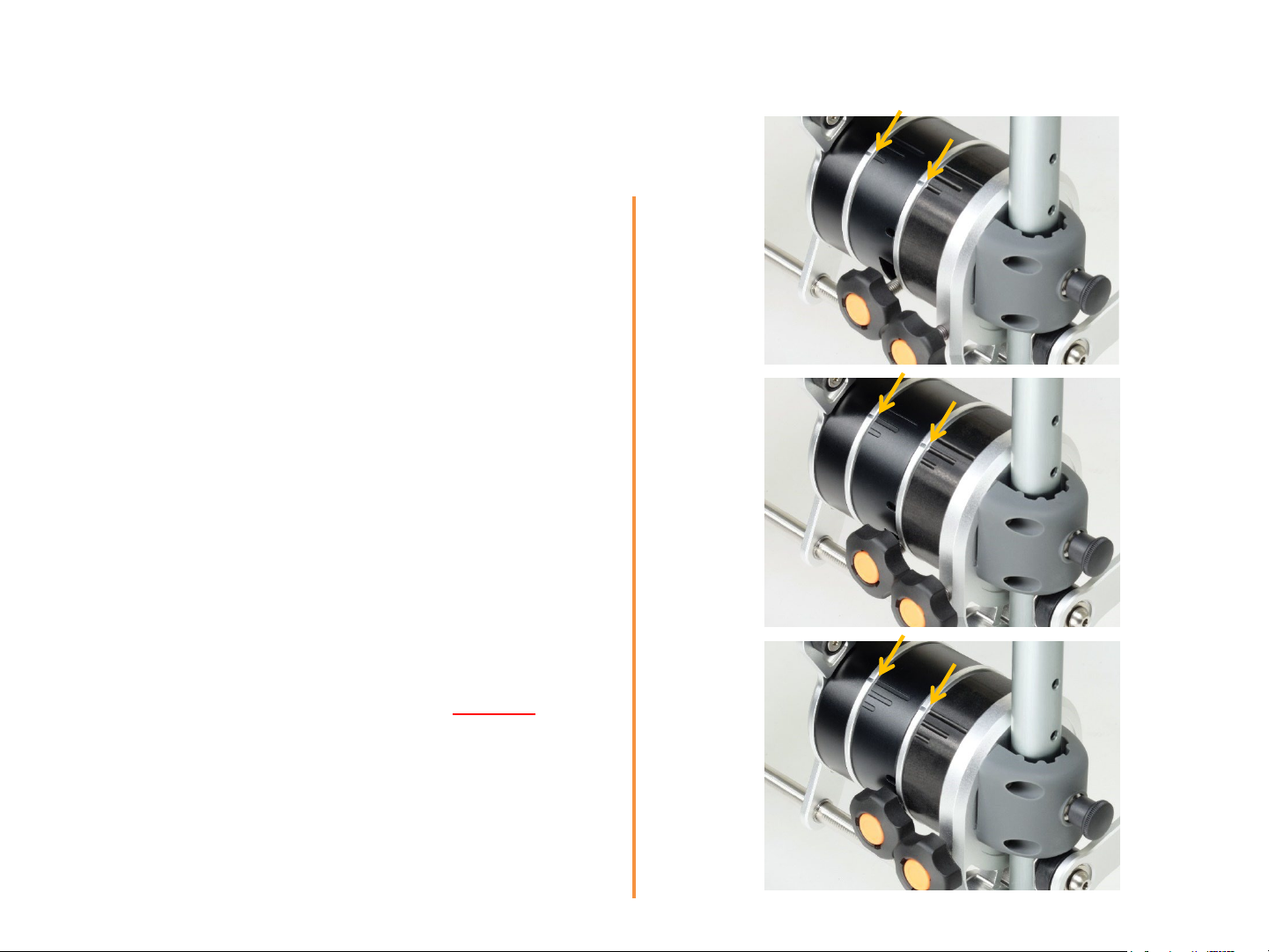
Starting on one side, turn Knob [A] to adjust
desired lift force which acts when the seat is
mostly lowered down; either to low (1),
[B]
[A]
3
2
1
medium (2) or high (3). Adjust Knob [B] to
the same level.
Repeat the same adjustments on the other
side.
Adjustments should be done with seat in
flipped up position.
Spring force should be adjusted equally
on
BOTH sides (all 4 drums).
Low
force
Medium
force
High
force
Page 20
4. Size Adjustments
4.1. Seat Height Adjustment
(for models M1-X, M2-X, L1-X and L-2X with seat; other models do not have seats).
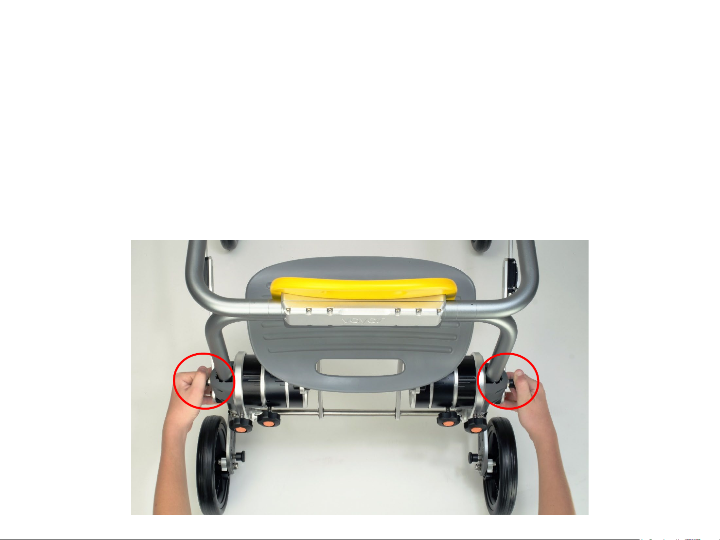
To adjust the Seat Height:
1. Pull the locks out and hold on both sides (left and right).
2. Slide the whole seat assembly up or down, holding on both sides.
3. Release the locks back in the holes on both sides, check both sides are positively locked
21
Page 21
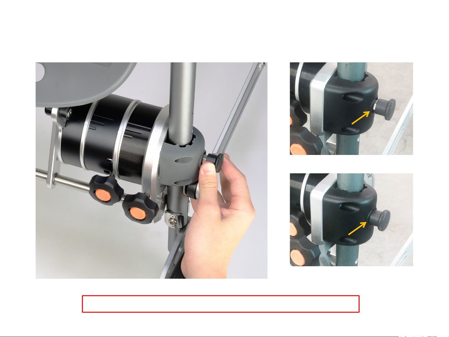
Pull the locks out on both sides (left and right).
Lock not fully engaged in hole
Lock fully engaged into hole
Caution: Please ensure pins are fully engaged before use.
22
Page 22
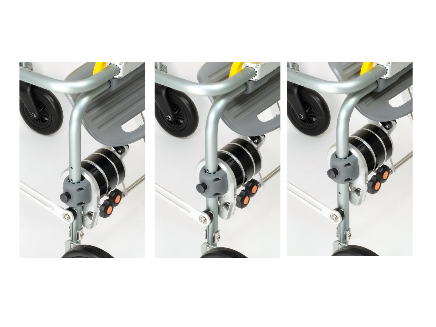
Sliding the seat assembly up or down after unlocking by pulling both
black spring plunger outwards.
Low
Seat Height
Intermediate
Seat Height
High
Seat Height
23
Page 23
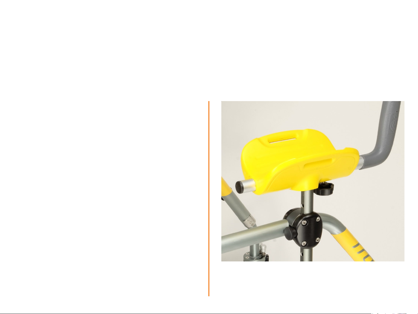
4.2. Forearm Support Adjustment
(for models M1-X, M3-X, L1-X and L-3X with armrests; other models do not have armrest).
Three knobs are used to adjust the
Armrests:
• Knob [1] controls the angle and
length/extension of the handle.
• Lock [2] controls the height of the
whole forearm support.
[1]
[2]
24
Page 24
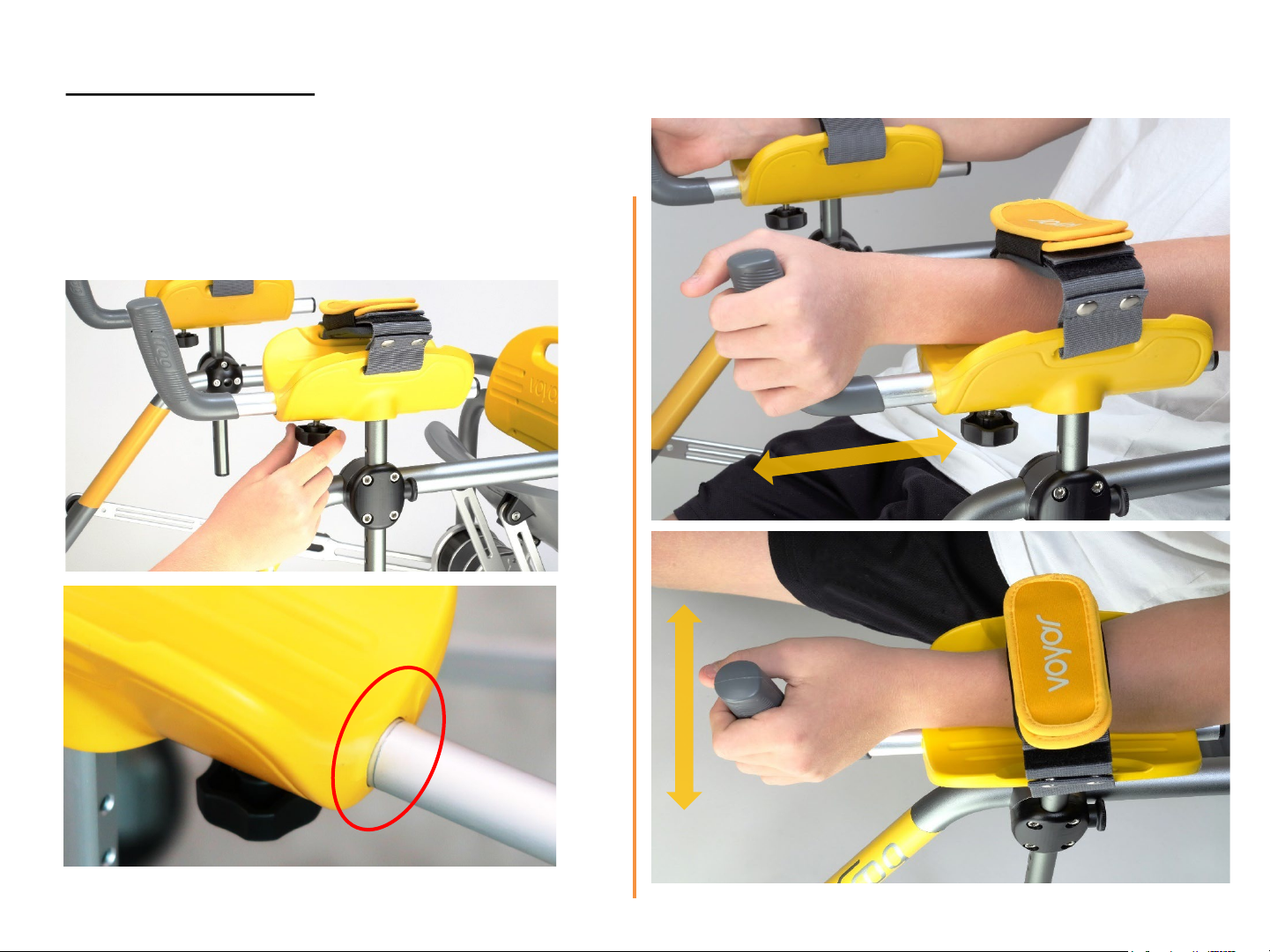
Handle Adjustment
To adjust length and angle:
1. Loosen knob [1].
2. Slide handhold forward or backward and
rotate to desired position; Re-tighten knob
[1]
Do not extend handles beyond limit mark.
25
Page 25
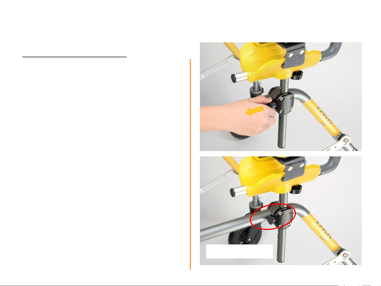
Armrest height adjustment
To adjust height:
1. Pull out lock [2] and hold it in position.
2. Slide post up or down to desired height.
3. Release lock back in, ensuring pin inside has
engaged with the hole on the shaft. If not,
gently slide the shaft up or down until pin
engages.
[2]
Fully engaged pin
26
Page 26
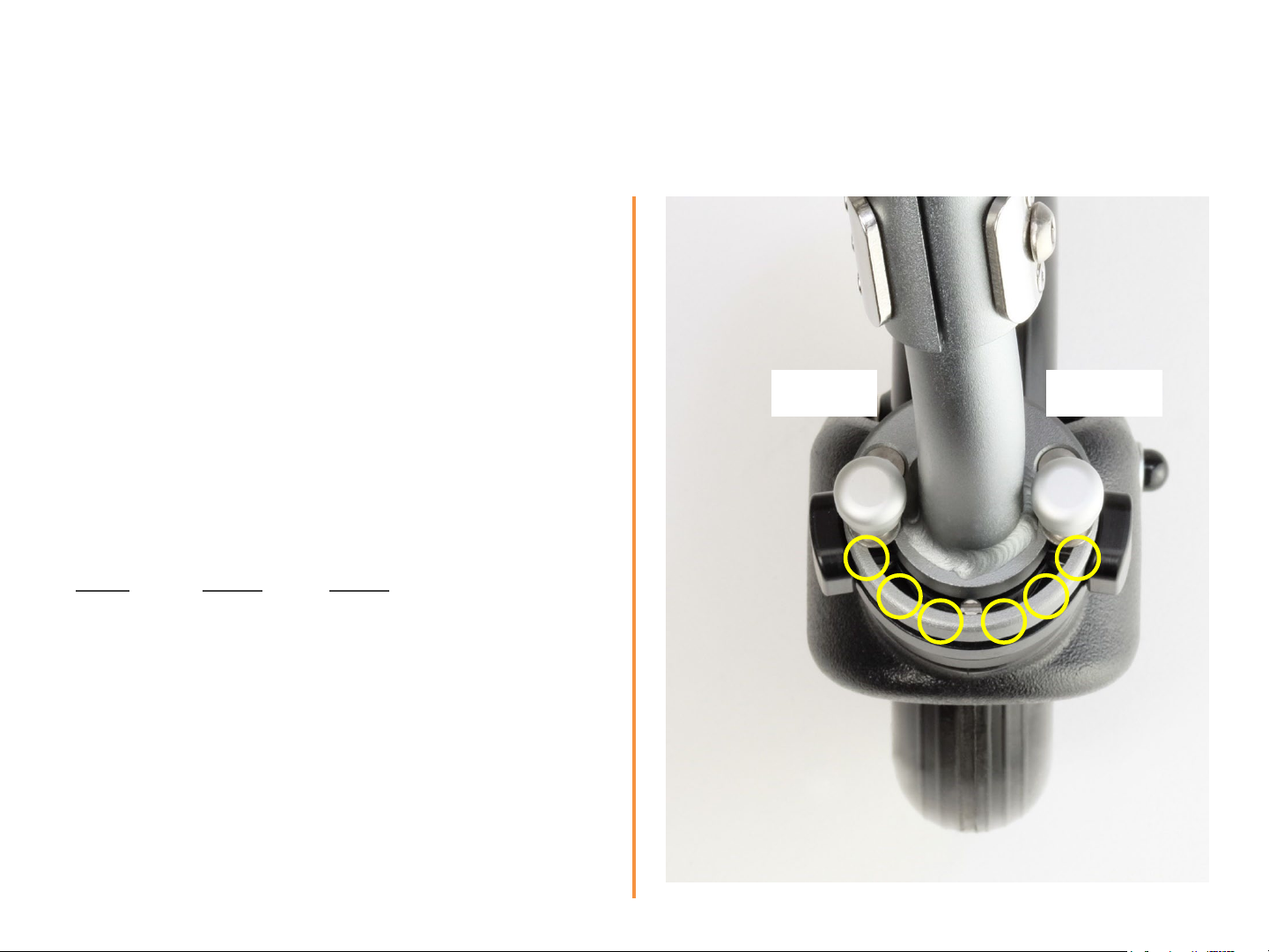
4.3. Front Wheel Swivel Limit Setting
Swivel limits can be independently adjusted
for each individual wheel, and each side
of the wheel (lock 1 & 2).
• Position 1: 0° Swivel
• Position 2: 30°Swivel
• Position 3: 60°Swivel
L R
1 1 2 1 3 1
2 2 2 2 3 2
1 3 2 3 3 3
L R L R
Lock 1 Lock 2
3
2
1
1
3
2
27
Page 27
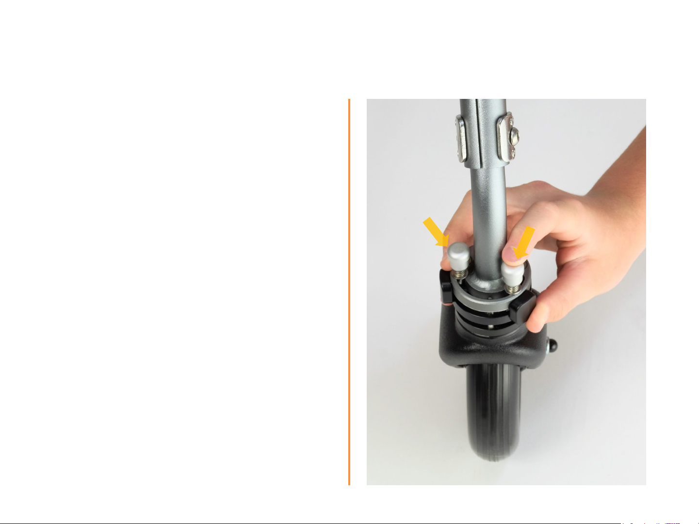
To adjust limits:
1. Push down lock [1].
2. Rotate pin and engage in desired
position (1, 2, 3).
3. Release lock 1.
Note: Ensure lock is fully engaged
4. Repeat with pin [2].
5. Repeat with other wheel.
[1]
[2]
28
Page 28
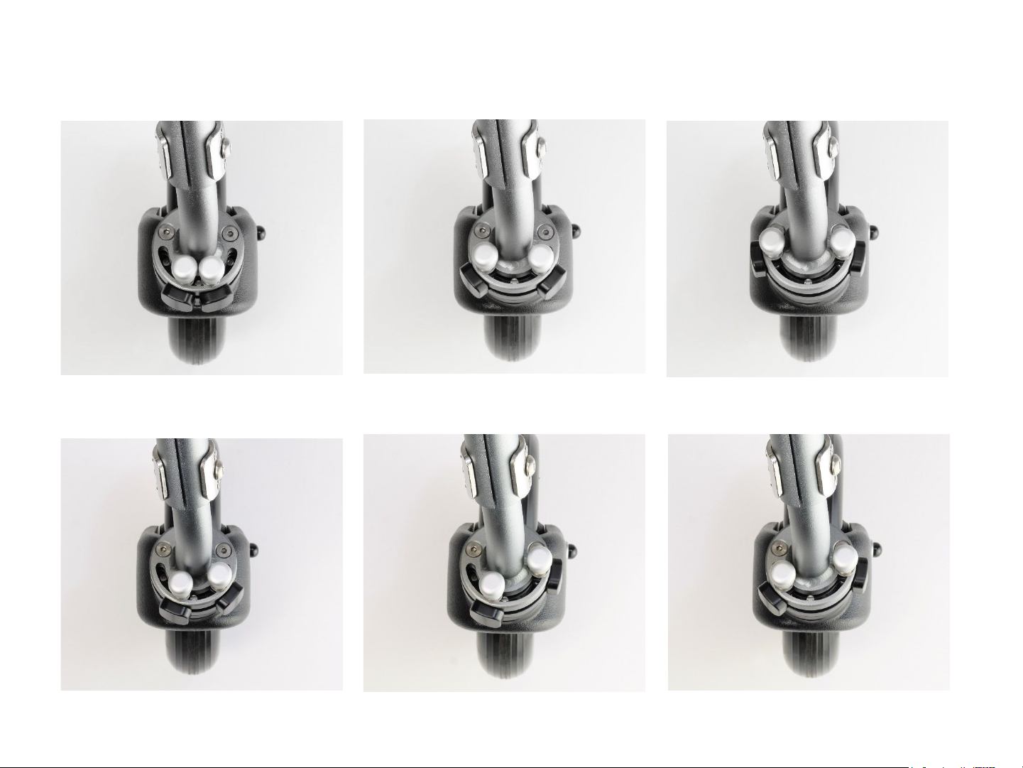
Example Swivel Configurations
Left: 1 Right:1 Left: 2 Right:2 Left: 3 Right:3
Left: 1 Right:2 Left: 1 Right: 3
Left: 2 Right: 3
29
Page 29
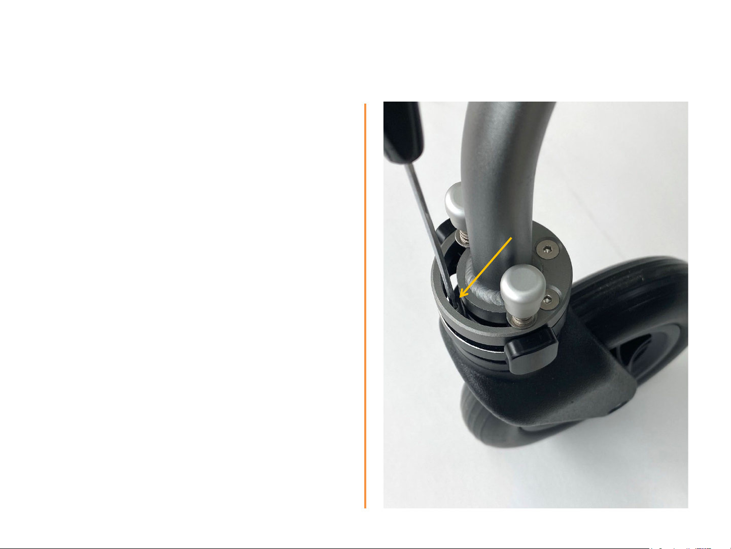
To remove limits and enable 360°
swivelling:
1. Unscrew the centering pin
2. Repeat on the other side
Note: Please keep centering pins in case the
limit locks should be reinstated at a later time
The front casters can now swivel all round
30
Page 30
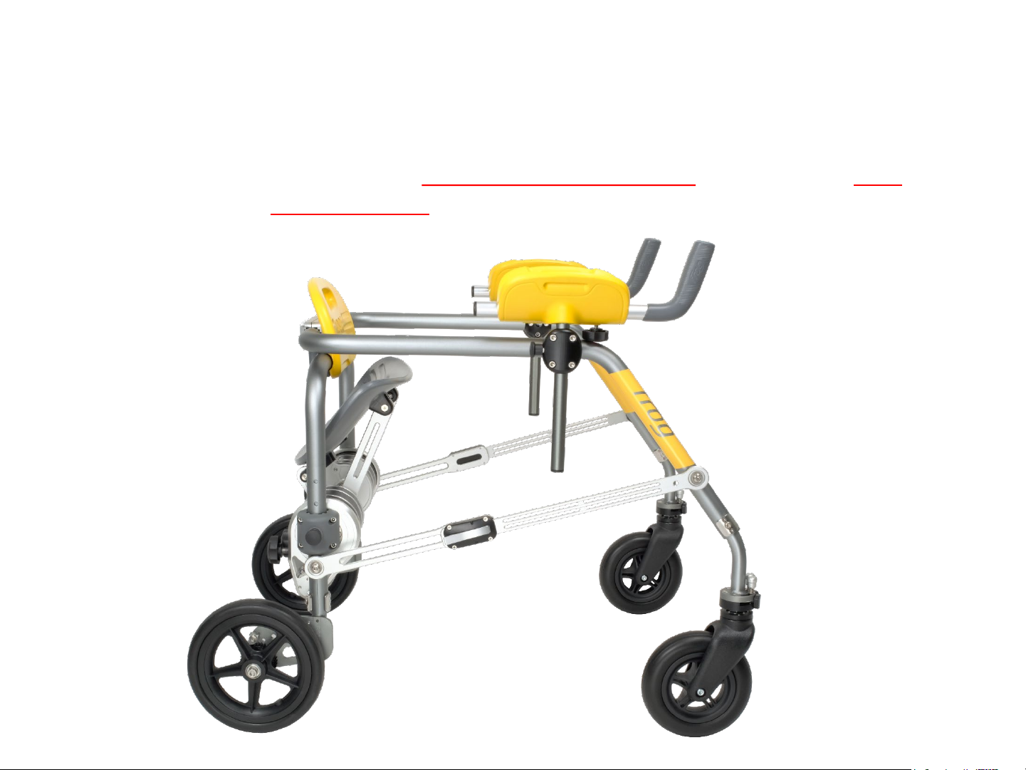
4.4. Frame Size Adjustment
Note: Please ensure walker is unfolded , locked & upright, and placed on even
ground/surface
before adjusting width & height.
31
Page 31

4.5. Frame Width Adjustment
An Allen key 2.5mm is required as tool for
the frame width adjustment.
1. The frame clamp holds the forward halfframes of the walker together. Loosen
screws (Allen key no. 3) just enough to be
able to slide the frames (orange arrows);
there is no need to remove them entirely.
2. Slide the left and right half segments in or
out relative to the clamp bar (orange double
arrows) referring to the markers indicating
narrow, medium and wide frame adjustment
(red arrows).
the 12
3. Re-tighten the screws of the clamp bar,
alternating progressively between left and
right as well as up and down mirror
positions.
32
Page 32
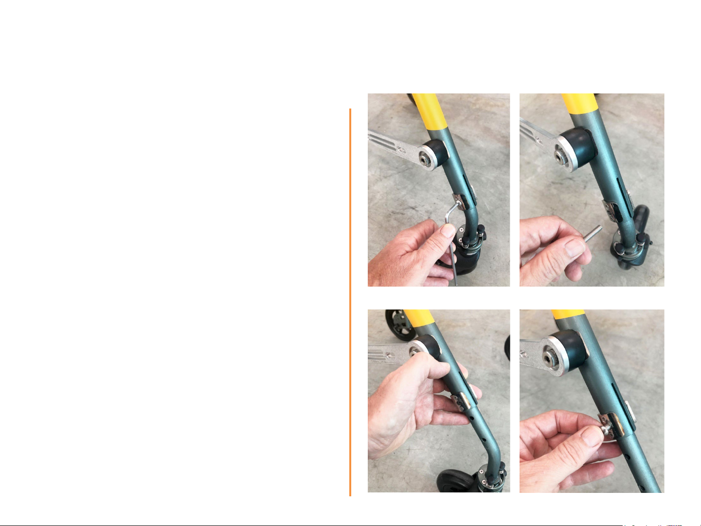
4.6. Frame Height Adjustment
An Allen key 4.0mm is required as tool for
the frame height adjustment.
A) Front wheels adjustment
1) Starting with one side, locate the clamp
screw. With an Allen key, un-tighten it.
2) Remove the screw completely
3) Slide the wheel attachment inside the
frame to the desired incremental
position. Check the screw holes line up
4) Re-insert the screw and tighten with
Allen key
5) Repeat on the other front side,
carefully checking identical position
(count number of holes from bottom)
1
3 4
2
33
Page 33
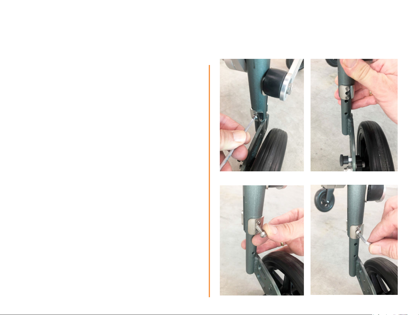
A) Rear wheels adjustment
1) Starting with one side, locate the clamp
screw. With an Allen key, un-tighten it.
2) Remove the screw completely
3) Slide the wheel attachment inside the
frame to the desired incremental
position. Check the screw holes line up.
Re-insert the screw.
4) Tighten the screw with Allen key
5) Repeat on the other front side,
carefully checking identical position
1 2
(count number of holes)
3 4
34
Page 34

5. Maintenance and Cleaning
5.1. Maintenance
After sufficient cleaning, checking for function and defects at regular intervals (approx. 1 month).
If damaged, the relevant parts must be replaced
1. Check the correct function and locking of the spring plungers on the seat adjustment (2), armrests
(2), folding links (2), parking brakes on the rear wheels (2) and steering wheels (4), as well as the
clamping screws for the handles on the armrests ( 2).
2. Check that all screws and nuts are properly tightened.
3. Check for dirt on the wheel hubs, steering bearings of the front wheels and the telescopic lock of
the folding lock; clean if necessary.
4. Check the correct function of the seat kinematics with special attention to the condition of the
suspension points of the seat.
5. Check the firm and torsion-free condition of the frame width adjustment behind the backrest
(screws firmly tightened).
6. Check the condition of the soft moldings (seat, back, armrests, handles) for cracks and breaks.
7. Check the condition of the wheels and tires for wear and damage; check the condition of the wheel
bearings (excessive play).
8. Check the plastic fastening parts (black) of the seat module and armrests for cracks, breaks and
discoloration.
9. Check the condition of the tubular frame parts for any cracks or bends.
10. Check that the anti-reverse is working properly on both rear wheels when engaged.
35
Page 35
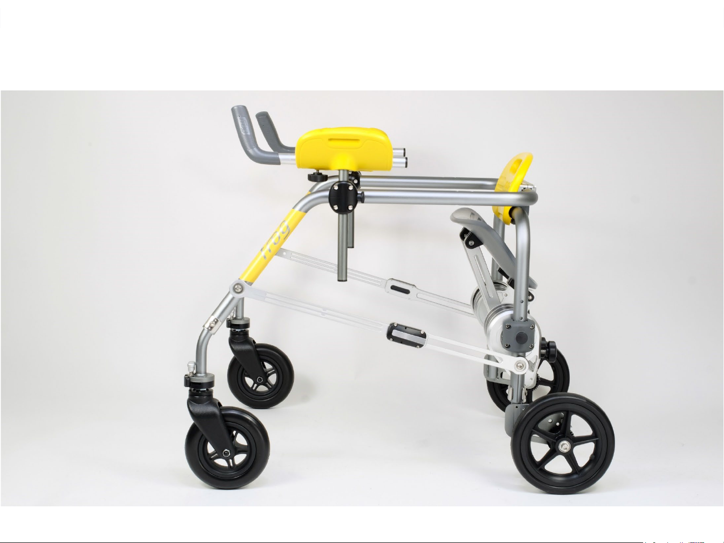
Clean all surfaces and
frames with a damp sponge
or cloth using soapy water.
For disinfection, wipe with
IPA alcohol
Remove coarse dirt from
wheel hubs.
5.2. Cleaning
36
Page 36

5.3. Re-use
The Voyar FROG is suitable for re-use. Before a handing over for re-use, the product should be
serviced and checked as below. Ideally, this re-processing is carried out by specialist dealers.
Depending on the intensity of use, a service life of 8 years can be expected (however, this does not
apply to wheels, other wearing parts and soft moulded parts)
1. Before re-use, the instructions for use (which should remain with the product) should be studied in
detail.
2. All maintenance points under 5.1 and a thorough cleaning should be carried out.
3. Any deficiencies identified should be corrected. In the case of damage, all affected parts should be
replaced (these parts are available from specialist dealers or directly from the manufacturer).
4. All size adjustments and adjustments for the new user should be made by trained or experienced
personnel.
37
Page 37

6. Specifications
M
Total size
Height (without armrests) 58 - 73 cm
Width 52 - 60 cm
Length 76 - 87 cm
Adjustment ranges
Frame height 52 - 67 cm
Frame width 38 - 46 cm
Seat height 32 - 53 cm
Armrest height 62 - 86 cm
Weight
Base model 5.0 kg
With armrests 6.5 kg
With seat (without armrests) 9.5 kg
With seat and armrests 11.0 kg
User limits
Weight up to 40 kg
Height 90cm – 140 cm
L
Total size
Height (without armrests) 74 - 81 cm
Width 63 - 82 cm
Length 76 cm
Adjustment ranges
Frame height 67 - 76 cm
Frame width 49 - 57 cm
Seat height 49 - 64 cm
Armrest height 74 - 95 cm
Weight
Base model 6.0 kg
With armrests 7.5 kg
With seat (without armrests) 10.5 kg
With seat and armrests 12.0 kg
User limits
Weight up to 70 kg
Height 130cm – 170 cm
Materials
Frame and seat mechanism Aluminium and stainless steel
Seat, backrest, armrests, grips PU foam with armature in stainless steel and aluminium
Fittings ABS
Wheels EVA
User Manual DP1601-281H_Eng
38
Page 38
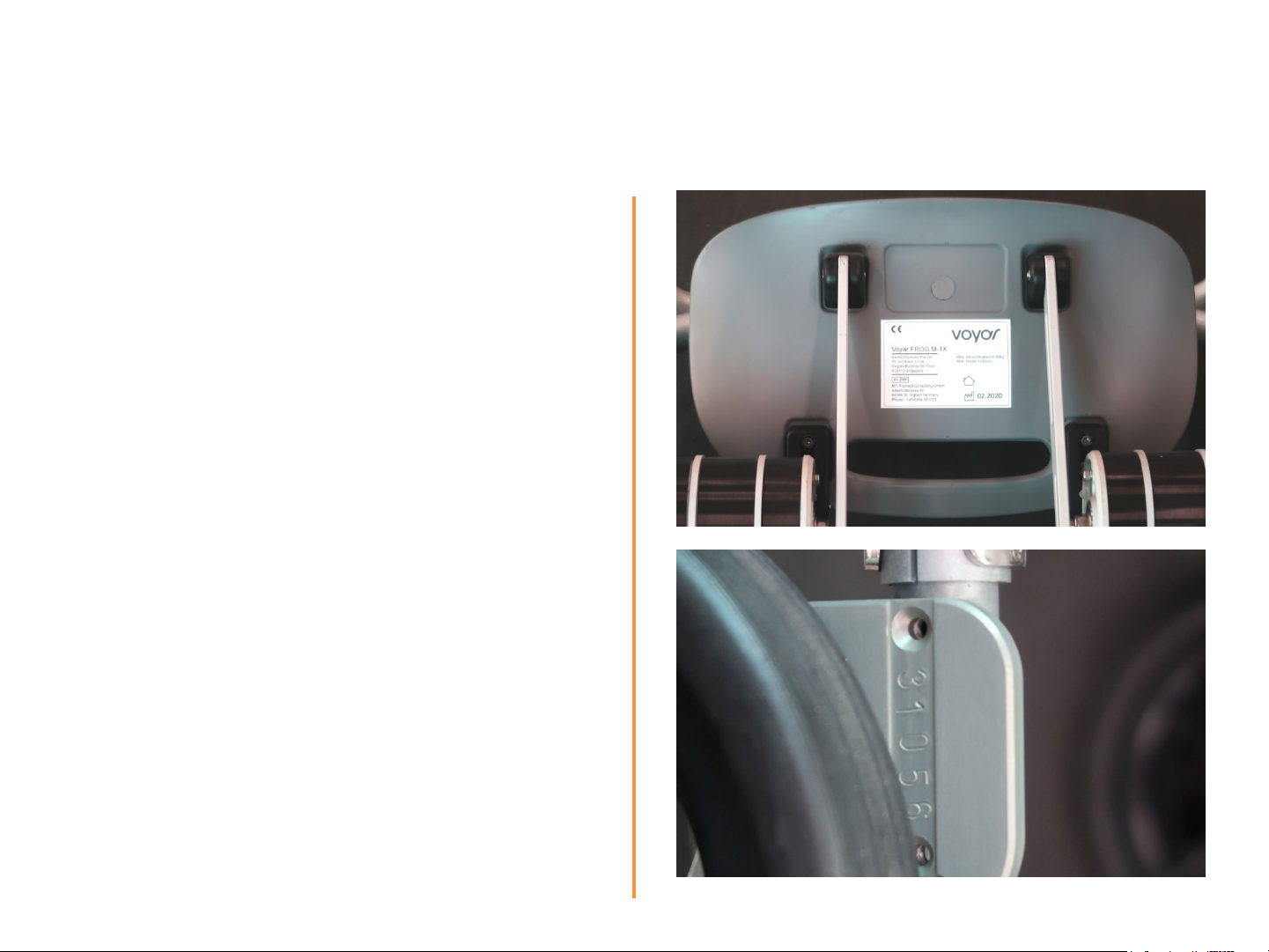
7. Identification
The product label is fixed under the seat. It
shows the exact model and the maximum
weight of the user.
For models without a seat, it is attached to the
rear frame, on the opposite side of the backrest
The serial number is stamped on the rear frame
close to the right rear wheel. Please indicate it in
the event of complaints or spare parts orders
User Manual DP1601-281H_Eng
39
 Loading...