

Page 1
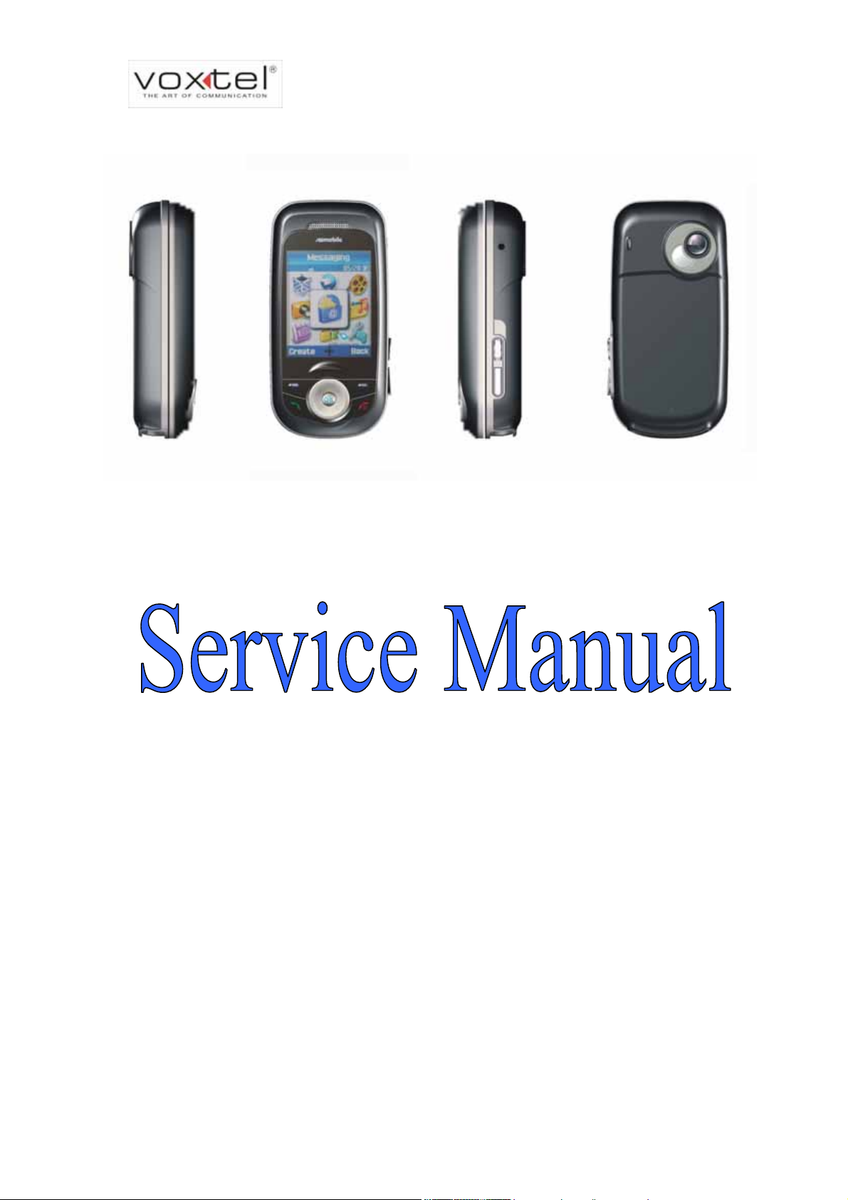
VS600 Service Manual
Model: VS600
Service Level: Level 1 ~Level 4
VOXTEL Technical Documentation 1
Page 2

VS600 Service Manual
TABLE OF CONTENTS
1 INTRODUCTION 4
1.1 OVERVIEW 4
1.2 SPECIFICATIONS 4
2 OVERVIEW OF GSM OPERATION 6
2.1 CELLULAR PHONE CONCEPT 6
2.2 GSM-GLOBAL SYSTEM FOR MOBILE COMMUNICATIONS 6
2.3 GSM SYSTEM 7
2.4 SERVICE AREA 9
3 VS600 HARDWARE SPECIFICATIONS 10
3.1 RF SUBSYSTEM 10
3.2 BASE-BAND SUBSYSTEM 11
3.3 BASE-BAND PARTS DETAILS 14
3.4 ACOUSTIC SPECIFICATIONS 21
3.5 CE MARKING 21
3.6 RELATED PERFORMANCE 22
4 CIRCUIT SCHEMATICS 23
4.1 MEMORY CIRCUIT 23
4.2 SIM CARD CIRCUIT 24
4.3 SPEAKER & RECEIVER 2-IN-1 CIRCUIT 24
4.4 MICROPHONE 25
4.5 LCM BACKLIGHT AND LED CIRCUIT 25
4.6 VIBRATOR CIRCUIT 26
4.7 POWER MANAGEMENT & CHARGING CIRCUIT 26
4.8 LCM FPC & LCM BACKLIGHT 27
4.9 BOARD TO BOARD CONNECTOR 28
4.10 HEADSET 29
4.11 BLUETOOTH & CHIP ANTENNA 29
4.12 HALL SENSOR CIRCUIT 30
4.13 MINI USB & MINI SD 31
4.14 UB & MB KEYPADS 31
4.15 MT6219 32
4.16 ANTENNA & SWITCH 33
4.17 AMPLIFIER (SKY77328) 34
4.18 MT6129 & SAW FILTERS 34
5 SOFTWARE DOWNLOAD 36
5.1 SYSTEM REQUIREMENTS 36
VOXTEL Technical Documentation 2
Page 3

VS600 Service Manual
5.2 VOXTEL USB2COM DOWNLOAD CABLE 36
5.3 INSTALLATION OF VOXTEL DOWNLOAD TOOL 37
5.4 HOW TO DOWNLOAD SOFTWARE? 38
6 DISASSEMBLY/ASSEMBLY PROCEDURE 41
6.1 INTRODUCTION 41
6.2 RECOMMENDED TOOLS 41
6.3 DISASSEMBLY PROCEDURE 42
6.4 ASSEMBLY PROCEDURE 51
6.5 EXPLODED VIEW 51
7 TROUBLESHOOTING 52
7.1 LEVEL 1 & 2 TROUBLESHOOTING CHART 52
7.2 MANUAL MMI TEST MODE 55
7.3 LEVEL 3 & 4 TROUBLESHOOTING-BASEBAND 57
7.3.1 BASEBAND SUBSYSTEM 57
7.3.2 KEY COMPONENTS PLACEMENT 58
MAIN BOARD ASSEMBLY-BOTTOM 58
MAIN BOARD ASSEMBLY-TOP 59
UPPER BOARD ASSEMBLY-BOTTOM 60
UPPER BOARD ASSEMBLY-TOP 60
BLOCK DIAGRAM 61
7.3.3 BASEBAND SUBSYSTEM CIRCUIT SCHEMATICS 61
7.4 LEVEL 3 & 4 TROUBLESHOOTING-RF 62
7.4.1 RF SUBSYSTEM 62
7.4.2 KEY COMPONENTS PLACEMENT 63
F
RONT-END & TRANSCEIVER 63
BLUETOOTH 64
BLOCK DIAGRAM 65
7.4.3 RF S
UBSYSTEM CIRCUIT SCHEMATICS 65
7.5 LEVEL 4 SERVICE GUIDELINE FOR RF SUBSYSTEM 66
7.5.1 RECEIVER PAT H 66
7.5.2 TRANSMITTER PAT H 71
7.5.3 AUTOCAL META TOOL 75
7.5.4 BLUETOOTH SUBSYSTEM 76
8 APPENDIX 78
E
VOXTEL Technical Documentation 3
XPLODED VIEW & PCB ASSEMBLY PLACEMENT 78
Page 4
A
A
1 Introduction
This document elaborates the functions and details of Voxtel VS600, a tri-band
VS600 Service Manual
GSM900/DCS1800/PCS1900
GSM feature phone with GPRS class-10 function, as we ll
as the information related to maintenance procedure and trouble-shootings.
1.1 Overview
VS600 is a MP3 feature phone with slide form factor . It equips with 1.8” 176x220 65k
TFT LCD display and a 1.3M pixels CMOS camera. Besides the excellent quality of
display, VS600 also features its acoustic performance: 64-polyphonic and MP3 ring
tones.
1.2 Specifications
Basic Features
Dimension (Excluding Antenna) 90x45x24
Weight (Flex & Volume) <85 g
Volume <82 cc
ntenna Embedded
Talk Time / Stand by time 2.5-5 hrs/140-200 hrs
Charging time Switching type (finish charging in 2.5 hours)
Main Display Type / Resolution / Color
Depth
Main Backlight Color / Type White light
Keypad Backlight Color / Type White light
TFT/1.8" 176*220/65K Color
Major Chipsets
Digital Base-band Chip MT6219
nalog Base-band Chip MT6219
Power Amplifier MT6318
Transceiver MT6129
Liquid Crystal Display Waxin
Memory Configuration (min.) 128 + 64
Backend IC No (ISP inside)
Camera CMOS Asia Optical
Battery NEC Cell
Bluetooth CSR
VOXTEL Technical Documentation 4
Page 5
VS600 Service Manual
A
A
I/O
I/O Connector Yes
External RF Connector Yes
C Charging Jack Yes
Earphone Mic. Jack Yes
Bluetooth Yes
USB Support Speed 921.6Kbps
USB Support Class Mass storage/CDCACM
USB Charging Yes
Extended Memory Mini SD & NAND Flash
Speaker 2 in 1
Mechanical Features
ppearance Semi-Auto Slider
Navigation Key 5 ways combined
Numeric Key 12 Pads
Side Key Yes
Strap Hole Yes
System / Service Support
Support Band 900/1800/1900
Speech Codec HR/FR/EFR
CSD / Fax Up to 14.4K
GPRS Multi-slot Class Class 10
GPRS Terminal Class Class B
GPRS Coding Scheme CS1, CS2, CS3, CS4
VOXTEL Technical Documentation 5
Page 6

VS600 Service Manual
2 Overview of GSM Operation
2.1 Cellular Phone Concept
The cellular system was first used to provide radiotelephone service in the frequency
range 890-960 MHz. A cellular system provides higher call handling capacity and system
availability than would be possible with conventional radiotelephone systems (those
which require total system area coverage on every operating channel) by dividing the
system coverage area into several adjoining sub-areas or cells.
Each cell contains a base station (cell site) that provides transmitting and receiving
facilities, for an allocated set of duplex frequency pairs (channels). Since each cell is a
relatively small area, both the cell site and the radiotelephone that it supports can
operate at lower power levels than would be used in conventional systems.
Using this technique, radiation on a given channel is virtually contained in the cell
operating on that channel and, to some extent, those cells directly adjacent to that cell.
Since the coverage area of a cell on a given channel is limited to a small area
(relative to the total system coverage area), a channel may be reused in another cell
outside the coverage area of the first. By this means, several subscribers may operate
within the same geographic area, without interference with each other, on a single
channel.
2.2 GSM-Global System for Mobile communications
Unlike former cellular systems, GSM uses digital radio techniques. The GSM system
has the following advantages over previous analogue systems:
International Roaming - Due to international harmonization and standardization, it will be
possible to make and receive calls in any country, which supports a GSM system.
Digital Air Interface - The GSM phone will provide an entirely digital link between the
telephone and the base station, which is, in turn, digitally linked into the switching
subsystems and on into the PSTN.
ISDN Compatibility - ISDN is a digital communications standard that many countries are
committed to implementing. It is designed to carry digital voice and data over existing
copper telephone cables. The GSM phone will be able to offer similar features to the
ISDN telephone.
Security and Confidentiality – Telephone calls on analogue systems can very easily be
VOXTEL Technical Documentation 6
Page 7
VS600 Service Manual
overheard by the use of a suitable radio receiver. GSM offers vastly improved
confidentiality because of the way in which data is digitally encrypted and transmitted.
Better Call Quality - Co-channel interference, handover breaks, and fading will be dealt
with more effectively in the digital system. The call quality is also enhanced by error
correction, which reconstructs lost information.
Efficiency - The GSM system will be able to use spectral resources in a much more
efficient way than previous analogue.
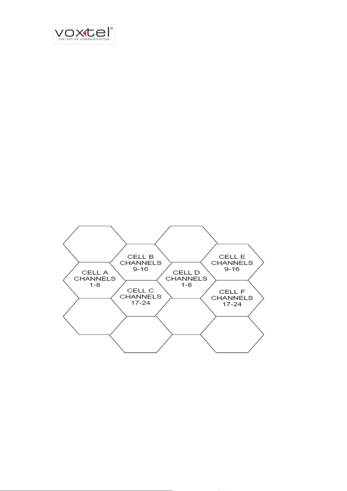
2.3 GSM System
In the figure below, the area bounded by bold lines represents the total coverage
area of a hypothetical system. This area is divided into several cells, each containing a
cell site (base station) operating on a given set of channels which interfaces
radiotelephone subscribers to the telephone switching system.
The radiotelephones themselves are capable of operation on any channel in the
system, allowing them to operate in any cell. Due to the low power requirements for
communications between radiotelephones in a particular cell and the cell site, operating
channels may be repeated in cells that are outside the coverage area of each other.
For example, presume that cell A operates on channels arbitrarily numbered 1
through 8, cell B operates on channels 9 through 16, cell C operates on channels 17
through 24 and cell D operates on channels 1 through 8 (repeating the usage of those
VOXTEL Technical Documentation 7
Page 8

VS600 Service Manual
channels used by cell A). In this system, subscribers in cell A and subscribers in cell D
could simultaneously operate on channels 1 through 8.
The implementation of frequency re-use increases the call handling capability of the
system without increasing the number of available channels. When re-using identical
frequencies in a small area, co-channel interference can be a problem. The GSM
system can tolerate higher levels of co-channel interference than analogue systems, by
incorporating digital modulation, forward error correction and equalization. This means
that cells using identical frequencies can be physically closer, than similar cells in
analogue systems. Therefore the advantage of frequency re-use can be further
enhanced in a GSM system, allowing greater traffic handling in hi gh use areas.
By incorporating Time Division Multiple Access (TDMA) several calls can share the
same carrier. The carrier is divided into a continuous stream of TDMA frames, each
frame is split into eight time slots. When a connection is required the system allocates
the subscriber a dedicated time slot within each TDMA frame. User data (speech/data)
for transmission is digitized and sectioned into blocks. The user data blocks are sent as
information bursts in the allocated time slot of each TDMA frame.
The data blocks are modulated onto the carrier using Gaussian Minimum Shift
Keying (GMSK), a very efficient method of phase modulation.
Each time an information burst is transmitted, it may be transmitted on a different
frequency. This process is known as frequency hopping. Frequency hopping reduces
the effects of fading, and enhances the security and confidentiality of the link. A GSM
radiotelephone is only required to transmit for one burst in each frame, and not
continually, thus enabling the unit to be more power efficient.
Each radiotelephone must be able to move from one cell to another, with minimal
inconvenience to the user. The mobile it self carries out signal strength measurement s on
adjacent cells, and the quality of the traffic channel is measured by both the mobile and
the base station. The handover criteria can thus be much more accurately determined,
and the handover made before the channel quality deteriorates to the point that the
subscriber notices.
When a radiotelephone is well within a cell, the signal strength measured will be high.
As the radiotelephone moves towards the edge of the cell, the signal strength and
quality measurement decreases.
Signal information provides an indication of the subscriber’s distance from the base
station. As the radiotelephone moves from cell to cell, its control is handed from one
VOXTEL Technical Documentation 8
Page 9

VS600 Service Manual
base station to another in the new cell.
This change is handled by the radiotelephone and base stations, and is completely
transparent to the user.
2.4 Service Area
A service area, where phone calls can be originated and received, is defined by the
system operators. (Because this is a radio system, there is no exact boundary that can
be drawn on a map.) If the telephone is outside a coverage area, the (no service)
indicator will illuminate and calls will be unable to be placed or received. If this happens
during a conversation, the call will be lost. There may also be small areas within a
particular service area where communications may be lost.
The radiotelephone’s identity information is held by its local GSM system in its Home
Location Register (HLR) and Visitor Location Register (VLR). The VLR contains identity
information on all local active radiotelephones. Should you roam to another area, system
or country the radiotelephones identity information is sent to the VLR in the new system.
The new system will then check the radiotelephones details with your home system for
authenticity. If everything is in order, it will be possible to initiate and receive calls within
the new cell.
VOXTEL Technical Documentation 9
Page 10
VS600 Service Manual
3 VS600 Hardware Specifications
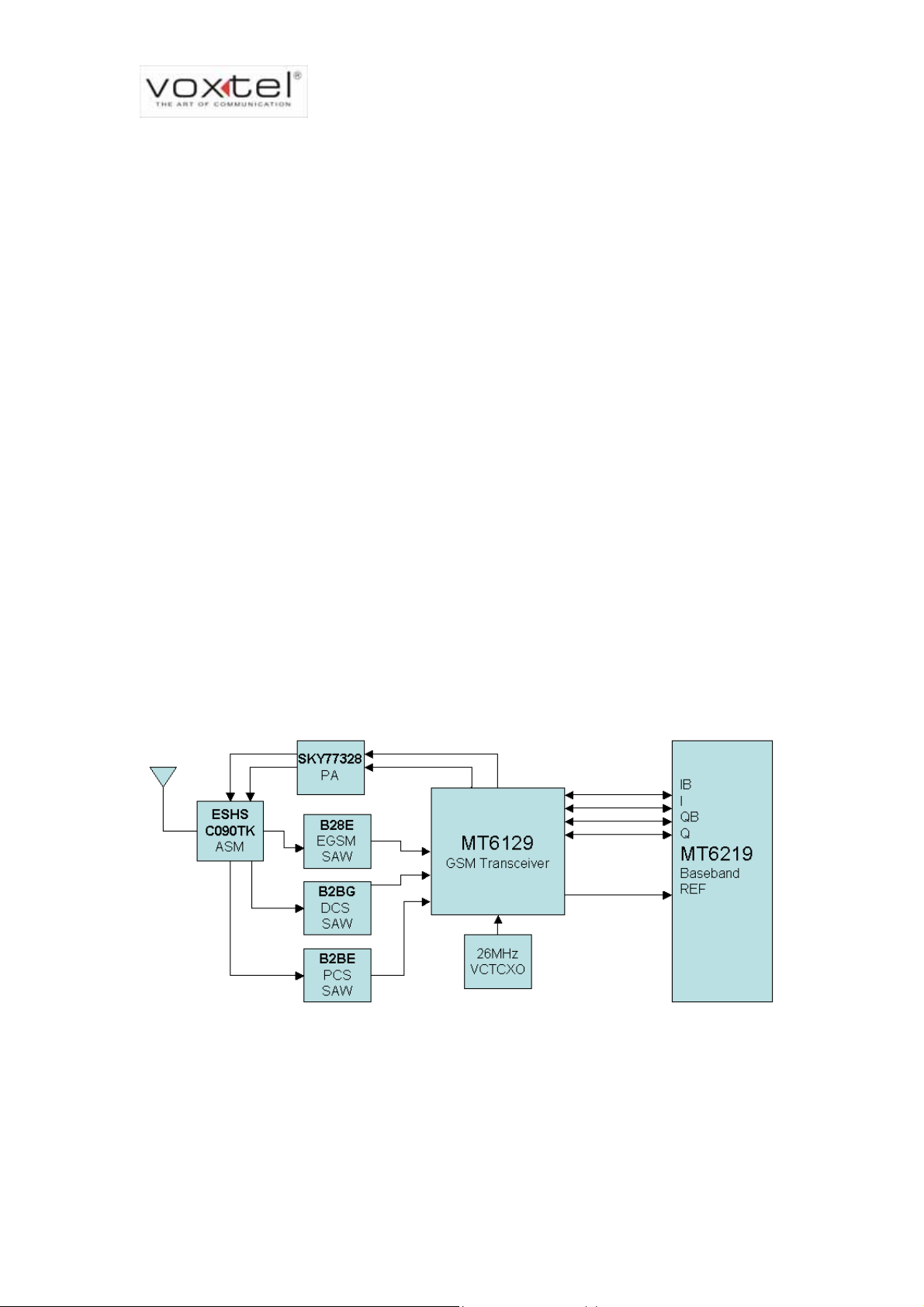
3.1 RF Subsystem
VS600 supports 900/1800/1900 bands as well as GPRS function. It supports GPRS
class 10, i.e. the maximum uplink slot number is 2; the maximum downlink slot number
is 4. The key components chosen for accomplishing the above requirements are listed
below:
Power amplifier --- SKY77328 (SKYWORKS), which is capable of supporting GPRS
class12 and quad-band application.
Transceiver IC --- MT6129 (MTK), which is GSM850/E GSM/DCS/PCS quad-band de sign
with GPRS class-12 capability.
Antenna switch --- C085TK (Hitachi metals), which is as the duplexer between
transmission / reception route for EGSM/DCS/PCS bands.
RF Clock --- 26MHz VC-TCXO, which is the fundamental reference frequency for
transceiver PLL synthesizer and the fundamental frequency of base band chipset after
divided by two.
The block diagram of RF section is as below:
RF Block Diagram
VOXTEL Technical Documentation 10
Page 11
VS600 Service Manual
3.2 Base-band Subsystem
VS600 adopts MTK ARM7EJ-S 32-bit RSIC GSM/GPRS BB chipset includes
MT6219, MT6305. It supports radio interface for EGSM900, DCS1800 and PCS1900.
For data service, it supports 14.4Kbits/sec GPRS. For voice servi ce, it support s adaptive
multi-rate, enhanced full-rate, full-rate, and half-rate. It also supports data encryption
algorithm for GSM network operation including A5/1 and A5/2 algorithms. Following
shows the base-band circuit block diagram.
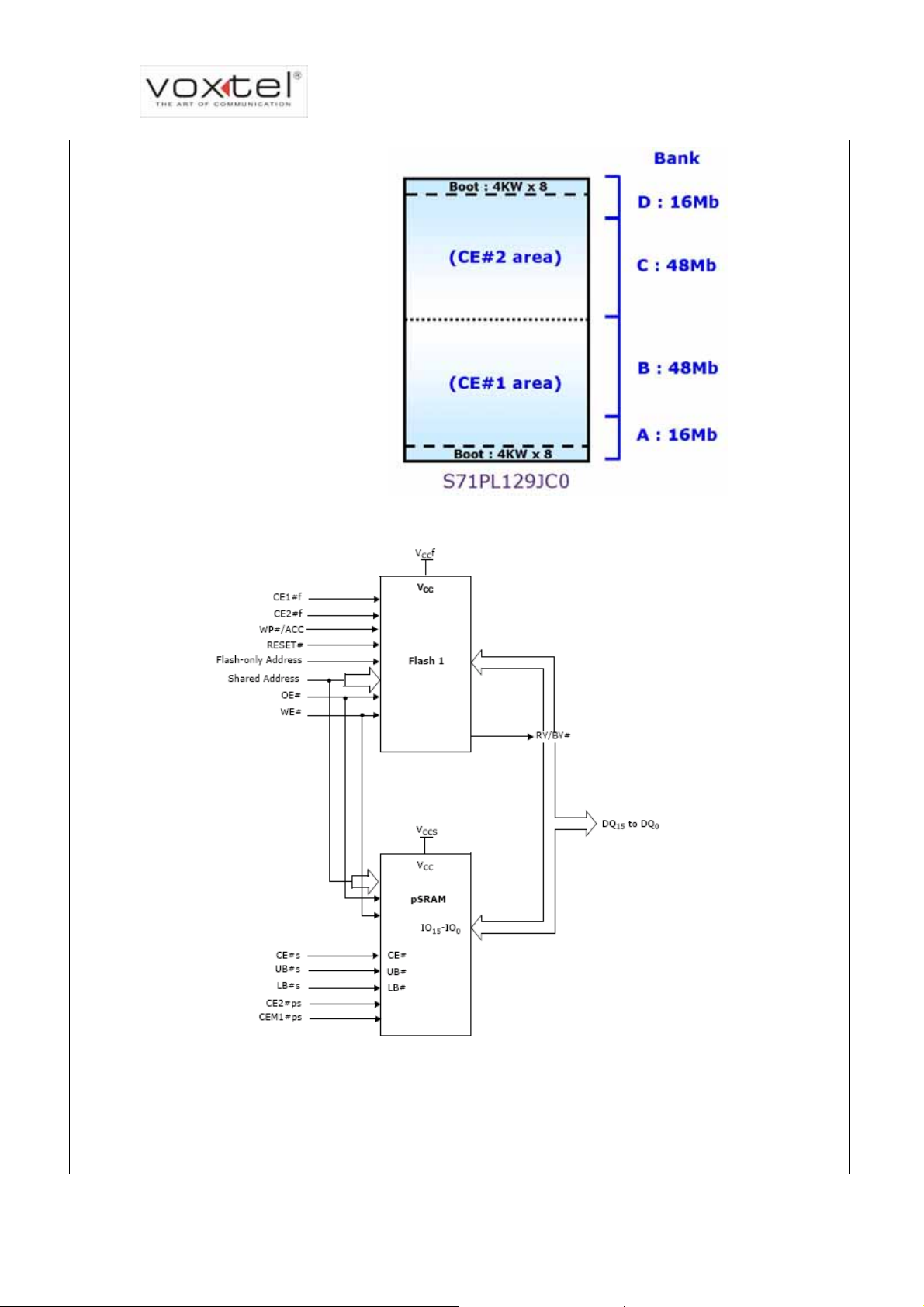
FLASH
SRAM
PSRAM
DEBUGGER
MELODY
LCD
CMOS
SENSOR
NAND
FLASH
LCD
JTAG
SPEECH/AUDI
O
INPUT
SPEECH/AUDI
O
OUTPUT
FM STEREO
RADIO INPUT
HIFI
STEREO
OUTPUT
ALERT
ER
PWM
SIM
EXTERNAL MEMORY
INTERFACE
IMAGE INPUT
MT6219
SERIAL
LCD
SERIAL
LCD
UART
USB
MMC/SD/MS
IRDA
Base-band block diagram
MSPRO
8-BIT PARALLEL
INTERFACE
SYSCLK
AFC
APC
TX I/Q
RX I/Q
AUXADC
SUPPLY
VOLTAGES
KEYPAD
1 2 3
4 5 6
7 8 9
0 #
*
TCVCXO
RF
MODULE
BPI
BSI
POWER
MANAGEMENT
CIRCUITRY
VOXTEL Technical Documentation 11
Page 12
VS600 Service Manual
A
Component and Function List
Product Segment Color basic feature phone
Product Description Case changeable mini phone
Memory configuration SPANSION 128Mb+64Mb (MCP)
Baseband Chip MT6219
Power Management IC MT6305
Power Amplifier SKY77328
Transceiver MT6129
LCM AUO 1.8” 176*220 65K TFT
1.3M CMOS Camera
SIA 1.3M Micron CMOS
sensor
Battery + Packing Cell: NEC (Lithium Ion)
Packing vendor: Tyco
Major Features List VS600
Supported Bands 900/1800/1900 MHz Tri-band
GPRS Class Class 12
Circuit Switch Data
Supported Voice Codec AMR/EFR/ FR/HR
Main LCD Display 1.8” 176(R, G, B)*220 65K TFT
Antenna Type
Charger Type Switch
Loud speaker-hands free Yes
CSD up to 9.6 kbps
Embedded
Polyphonic (chords) S/W Polyphonic up to 64 tones
WAP WAP 2.0
EMS R4 Yes
Concatenated SMS Yes
Intelligent Text input T9
Games Yes
VOXTEL Technical Documentation 12
Page 13
VS600 Service Manual
JPEG Yes
Bluetooth CSR Bluetooth 1.1
USB Connection USB 1.1 Slave
UV light Yes
PC Tools Download/ Modem driver
Wallpapers Yes
Melody Composer Yes
ME Address book 250
Caller Photo Display Yes
Caller Groups Y es
Calendar/Note/Appointment Yes
Alarm Clock Yes
Calculator Yes
VOXTEL Technical Documentation 13
Page 14

VS600 Service Manual
A
3.3 Base-band Parts Details
MT6219
The MT6219 is the baseband processing solution offered by MTK as part of the 32-bit
ARM7EJ-S RSIC processor chipset Family. The chip integrates a powerful DSP,
ARM7EJ-S processor, and extensive set of peripherals that support applications such
as MMS, EMS and MP3. The MT6219 allow advanced speech algorithms, such as
MR and signal processing function such as echo suppression, cancellation and
noise reduction. The MT6219 supports pseudo-static RAM, page and burst flash
memories, USB, SD/MMC and devices such as camera modules. It can be divided
into three main subsystems.
● MCU Control processor subsystem
ARM7EJ-S 32-bit RISC Processor
26/52 MHz operating frequency
JAVA hardware acceleration
512 KB zero-wait-state on-chip SRAM
● Multi-media subsystem
JPEG codec
2D accelerator
Wavetable synthesis
MT6305
MPEG-4/H.263 codec
Full speed USB 1.1
High throughput hardware re-size capable of tailoring image to arbitrary
MMC/SD, MS and MS PRO host controller
DSP recorder
● User interface
6-row x 7-column keypad scanner
3 UARTs with hardware flow control and speed up to 921600 bps
7-channel auxiliary ADC
Six level or edge sensitive external interrupts
The MT6305 is a power management system chip optimized for GSM handsets. It
contains seven LDOs, one to power each of the critical GSM sub-block. Sophisticated
controls are available for power-up during battery charging, keypad interface, and
RTC alarm. The MT6305 is optimized for maximum battery life, featuring a ground
current of one 107uA and 187uA when the phone is in standby and operation
respectively.
The MT6305 contains three open drain output switches for LED, alarm, and vibration
VOXTEL Technical Documentation 14
Page 15

Microphone
Loud Speaker
VS600 Service Manual
control. The SIM interface provides the level shift between SIM card and
microprocessor.
● Power Management Section
Voltage regulator
Battery charger
Battery production
MARQUESS MM-OB622S-42C33C10
Sensitivity: -42±3 dB at 1kHz, 1V/Pa
Output Impedance: 2.2k+-10% ohm at 1kHz,
S/N Ratio (A curve): min 58 dBv/Pa at 1kHz,
Dimension: φ 6.0 * 2.2 mm
Directional characteristic: omni-directional
Operating voltage: DC 2V
Part number: Speaker-Receiver dual type MT-2014ESF
Impedance: 8 ± 1.2 at 1KHz, 1Vrms.
SPL for Dynamic Speaker: 100 ± 3 dB at 0.5W 1KHz.
Stacked-MCP
Architecture
(128Mbit Flash +
64Mbit PSRAM)
SPL for Dynamic Receiver: 123dB ± 3dB at 1.0KHz, 100mV with IEC R318 coupler.
Resonance Frequency (Fo): 800Hz ± 160 Hz, 1V
Rated Input (Nom./Max.) for Speaker: 0.5 W/ 0.8W
Frequency Range:Fo ~ 20 kHz. (Receiver: 300Hz~3.4kHz)
Dimension: 20 × 14 × T4.6 [mm]
Spansion S71PL129JC0
Stacked Multi-Chip Product (MCP) Flash Memory and pSRAM
128 Megabit (8M x 16-bit) CMOS 3.0 voltage-only simultaneous operation, page mode flash memory
with 64 Megabit (4M x 16-bit) pseudo-static RAM.
Power supply voltage of 2.7 to 3.1 Volt
Access time: 65ns flash and 70ns pSRAM
Operating temperature: -25°C to +85°C (wireless)
-40°C to +85°C (Industrial)
Both top and bottom boot blocks in one device.
VOXTEL Technical Documentation 15
Page 16
VS600 Service Manual
Bank structure
MCP block diagram
VOXTEL Technical Documentation 16
Page 17
Display
VS600 Service Manual
Jemitek 1.8” 176*220 65K TFT LCM
Specifications:
ITEM STANDARD VALUE UNIT
Number of Pixels 176 x (R, G, B) × 220 dots
1.3M CMOS
Sensor
Outline Dimension
34 (W) × 46.7 (H) × 3.0
mm
(T)
Active Area
Pixel Pitch
27.984 (W) × 34.98 (H)
0.159 (W) × 0.159 (H)
mm
mm
Weight g
LCD type TFT (Transmissive)
Viewing Direction 12 O’clock
Backlight White LED
Driver IC Samsung S6D0118
.
ASIA Optical BASCH0300
The BASCH0300 is mobile phone camera module with Micron 1/3” SXGA CMOS
sensor. It is 1.3M fixed focus camera module for mobile phone and includes 3 plastic
Lens.
Features
The BASCH0300 features a state-of-the-art architecture, allowing extremely low
Back Light
Keypad
power consumption and miniature size. The following are the product highlights.
Sensor Array
●1/3" optical format
●SXGA resolution 1280x1024
●3.6µm x 3.6µm square pixels
●Integrated 10 Bit ADC
●RGB mosaic with micro-lens for high sensitivity
●Programmable frame rate up to 15 fps SXGA and 30 fps QSXGA
The backlight on the module is single light guide. SW adjusts the brightness by changing the ON/OFF
duty cycle of on-chip PWM generator.
The keypad is a matrix. The columns, KEYCOL(6:0) are connect to the keyboard
interface of MT6219, and are usually driven low. The rows, KEYROW(5:0) are
connected to the keyboard interface of MT6219 and are internal pulled-up. When a
key is pressed, the appropriate row is connected to one of the columns, and forced
low, then causing an interrupt.
VOXTEL Technical Documentation 17
Page 18
VS600 Service Manual
Attach VS600 keypad matrix comparison table.
KCOL6
GND [Power/ End key]
KCOL0 KCOL1 KCOL2 KCOL3 KCOL4
KROW0 [Send] [Vol_Up] X [Vol_Down] X
KROW1 [Up] [Soft L] X [Soft R] X
KROW2 [Down] [1] [2] [3] X
KROW3 [Left] [4] [5] [6] X
KROW4 [Right] [7] [8] [9] X
KROW5 [Mid] [*] [0] [#] X
.
Vibrator
I/O connector
Adaptor
Part number: JA HWA
Rated voltage: 3 VDC
Rated current: Max. 80mA
Terminal resistance: 35 ohm +- 15%
Rated speed: 13000 +- 3000 rpm
Mechanical noise: Less than 50dB
Operation temperature: -30°C ~ 70°C
Storage temperature: -40°C ~ 85°C
Mini-USB connector
INPUT CHARACTERISTICS
●Input Voltage and Frequency
The power supply shall meet all specifications when powered from the following Sources.
Item Minimum Nominal Maximum
Voltage 90V 100/240V 264V
Frequency 47Hz 50/60Hz 63Hz
●Efficiency
The power supply efficiency shall be greater than 55 % when measure at full rated
load, nominal input voltage.
VOXTEL Technical Documentation 18
Page 19

VS600 Service Manual
●Input Current
The AC mains steady state RMS input current shall be 0.3 Amps maximum at rated
input, full load condition.
●Inrush Current
The AC mains single-cycle peak inrush current shall be limited to 30 amps cold and
coinciding with the AC mains voltage 264Vac. The power supply shall cause no
damage with the hot start inrush under 40 degree C ambient temperature.
●Leakage Current Requirement
The power supply ground leakage current, when measured per the test
configuration, shall not exceed 0.25mA at input voltage of 264Vac/50Hz for Class
II.
●
Over-Voltage Requirement (input)
The supply will operate safely up to 240Vac. the SMP must not fail in catastrophic
manner (i.e. no fire, Flames, sparks, melting)
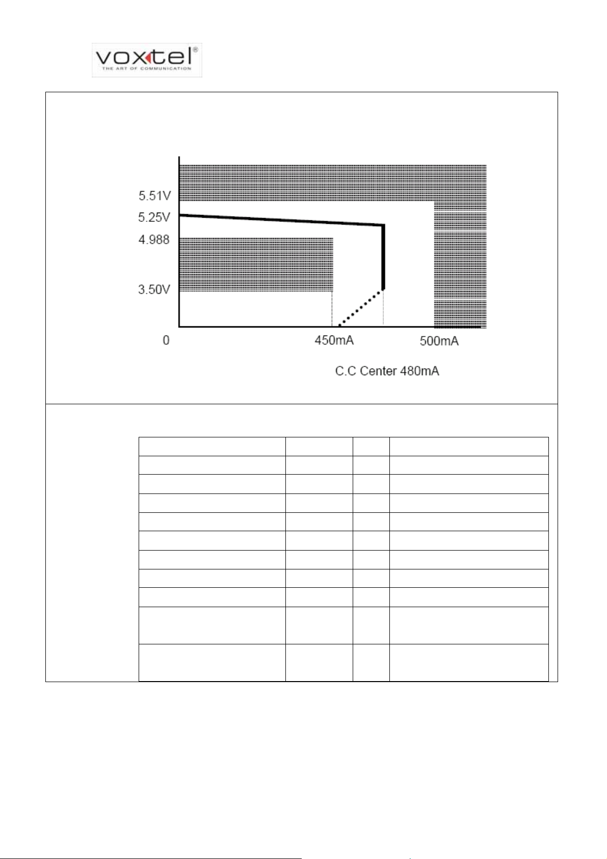
OUTPUT CHARACTERISTICS
●Output Voltage
The power supply shall be regulated DC output of 5.25Vdc±5%, the voltage shall
be measured at the power supply output connector.
●Output Current
Output Current (Iout): Continuous operation: 480mA
●Temperature
Operating: -0 to 45 degrees C.
Non-operating: -10 to 70 degrees C.
●Humidity
10~ 90% relative humidity, non-condensing during operating temperature. 5~ 95%
relative humidity, including condensation during non-operating temperature.
●Transient Response
The voltage regulation limits shall be maintained over the AC input range. The
power supply shall maintain output voltage regulation subject to the conditions
listed. The transient response measurement shall be made with a load changing
VOXTEL Technical Documentation 19
Page 20
VS600 Service Manual
repetition rate of 100 Hz. The load slew rate shall not be greater than 0.1 A/us.
During transient steps, the regulation must be maintained within the limits of figure.
Battery Packing
Battery cell: NEC Li-Ion 700mAh
NEC cell + PCM
Description Specification Unit Condition
Cell model NEC
Nominal Capacity 700 mAh
Nominal Voltage 3.7 V
Charge voltage 4.2 V
Final discharge voltage 2.75 V
ICP043443AL
Maximum Charge Current 700 mA 1C
Maximum Discharge Current 1400 mA 2C
Internal Resistance <145 m
Operating Temperature
Range
0~+45
-20~+60
Storage Temperature Range -20~+60
℃
℃
Charge
Discharge
Within 6 months;
Capacity recovery rate 85%
VOXTEL Technical Documentation 20
Page 21

VS600 Service Manual
3.4 Acoustic Specifications
GSM 11.10 – 30.1 Sending sensitivity/frequency response
GSM 11.10 – 30.2 Sending loudness rating (SLR)
GSM 11.10 – 30.3 Receiving sensitivity/frequency response
GSM 11.10 – 30.4 Receiving loudness rating (RLR)
GSM 11.10 – 30.5.1 Side Tone Masking Rating (STMR)
GSM 11.10 – 30.6.2 Telephone acoustic coupling loss – Stability margin
GSM 11.10 – 30.7.1 Distortion-Sending
3.5 CE marking
Safety:EN60950
EMC:ETS300 342-1
EN55022 EMI: ITE-Radio Disturbance Characteristic
EN61000-4-3 RS : Radiate, Radio-Frequency, and Electromagnetic Field
Immunity Test
EN61000-4-2 ESD:Electrostatic Discharge Immunity Test
EN61000-4-4 EFT:Electrical Fast Transient/Burst Immunity Test
EN61000-4-6 CS:Immunity to Conducted Disturbances
ISO7637-1/-2 Transient and Surge, Vehicular Environment
EN61000-4-11 Voltage Dip, short Interruptions and voltage Variations Immunity
Test
EN61000-4-5 Surge:Surge Immunity Test
VOXTEL Technical Documentation 21
Page 22
VS600 Service Manual
3.6 Related Performance
Operating Range
Battery mode
Charging mode
Power consumption
Talk mode
Sleep mode
GPRS mode, 1 TX
slot
Power On: 3.4V < Vbat < 4.3V
Power Off: Hardware: Vbat < 3.2V, Software: Vbat < 3.4V
Low Battery Alert: Vbat = 3.4V
Maximum Charge Current: 500mA
Maximum Charge Voltage: 5.5V
Maximum Charge Time: less than 3 Hours
Maximum Current: (320mA) @ GSM band, PO = 32dBm
Maximum Current: (250mA) @ DCS band, PO = 29dBm
Maximum Current: (6mA) @ paging rate = 2
Maximum Current: (3.5mA) @ paging rate = 9
Maximum Current: (320mA) @ GSM band, PO = 32dBm
Maximum Current: (250mA) @ DCS band, PO = 29dBm
VOXTEL Technical Documentation 22
Page 23

VS600 Service Manual
4 Circuit Schematics
4.1 Memory Circuit
VOXTEL Technical Documentation 23
Page 24
VS600 Service Manual
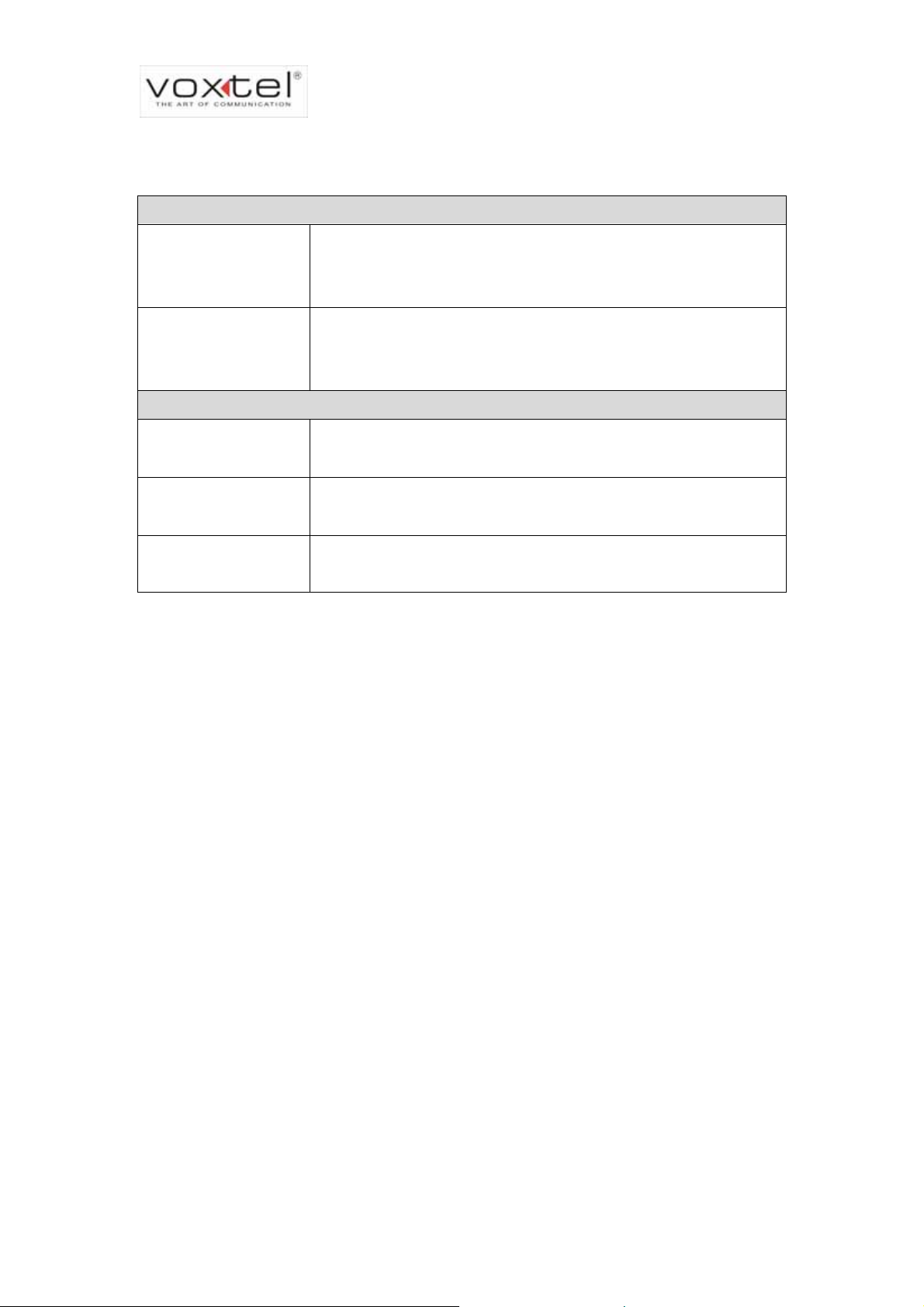
4.2 SIM Card Circuit
4.3 Speaker & Receiver 2-in-1 circuit
VOXTEL Technical Documentation 24
Page 25
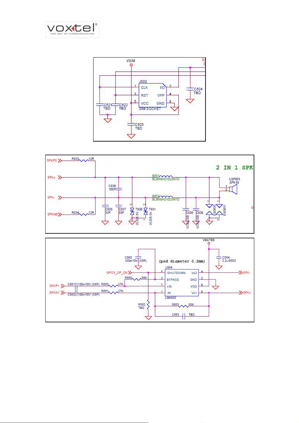
4.4 Microphone
VS600 Service Manual
4.5 LCM Backlight and LED Circuit
VOXTEL Technical Documentation 25
Page 26

VS600 Service Manual
4.6 Vibrator Circuit
4.7 Power Management & Charging Circuit
VOXTEL Technical Documentation 26
Page 27

VS600 Service Manual
4.8 LCM FPC & LCM Backlight
VOXTEL Technical Documentation 27
Page 28

VS600 Service Manual
4.9 Board to Board Connector
VOXTEL Technical Documentation 28
Page 29

VS600 Service Manual
4.10 Headset
4.11 Bluetooth & Chip Antenna
VOXTEL Technical Documentation 29
Page 30

VS600 Service Manual
4.12 Hall Sensor circuit
VOXTEL Technical Documentation 30
Page 31

VS600 Service Manual
4.13 Mini USB & Mini SD
4.14 UB & MB Keypads
VOXTEL Technical Documentation 31
Page 32

4.15 MT6219
VS600 Service Manual
VOXTEL Technical Documentation 32
Page 33

VS600 Service Manual
4.16 Antenna & Switch
VOXTEL Technical Documentation 33
Page 34

VS600 Service Manual
4.17 Amplifier (SKY77328)
4.18 MT6129 & SAW Filters
VOXTEL Technical Documentation 34
Page 35

VS600 Service Manual
VOXTEL Technical Documentation 35
Page 36

VS600 Service Manual
5 Software Download
5.1 System Requirements
Operation system: WinXP / WinNT / Win2000.
CPU: Pentium3 1 GHz or higher.
Hard Disk: Free 100MB space.
Memory: 256MB RAM.
Input Device: Keyboard and mouse
Cable: RS232 Cable (Voxtel cable)
5.2 Voxtel USB2COM Download cable
1 Please don’t insert the US B cable into your computer before the installation of the driver.
2 There will be a directory “(US-001) USB To Serial Cable V1.1” in the provided CD. Please
run the installation program: “Driver Installer.exe” in the “98~xp” directory if your OS is
windows 98~xp. We don’t support other OS now.
3 After install the driver of this USB2COM cable. The program will ask you to restart the
computer.
4 After re-start the computer and the setup procedure, please insert the USB2COM cable
and there will be a new COM port in your system.
5 Please remember the COM port number in “Device Manager”. You would need this value
to configure your DL tool.
VOXTEL Technical Documentation 36
Page 37

VS600 Service Manual
r
r
5.3 Installation of Voxtel Download Tool
Voxtel download tool is for communication between PC and VS600. It’s for loading
software into VS600. You can download it from Voxtel. The installation procedure is
simply to put all files under same folder.
Put all files under
same folder.
Logo
Double click the executive file to activate the tool. Then you will see the GUI popped
up as followed picture:
Main Menu Ba
File Information
Progress Bar
Status Ba
VOXTEL Technical Documentation 37
Page 38

VS600 Service Manual
5.4 How to Download Software?
Before you begin using the tool, you must set your COM port and Baud Rage first. The
tool will show the available COM port in the PORT, Baud Rate, like following figures.
VOXTEL Technical Documentation 38
Page 39

VS600 Service Manual
Please power off VS600 first. Then connect the Voxtel download cable to the handset.
After connecting the PC and device, we have to select the correct data files. You can
download data files from Voxtel. Remembe
Next you need to click “FlieOpenLinkMap” on the GUI. After selecting the
scatCASTOR.txt, the tool will parse the contents of the file including the segment and
Address. Right after that, click the “Download” button to get the data transferrin g process
r to put all data in same folder.
Put all data files
in same folder
ready.
Click Here
VOXTEL Technical Documentation 39
Page 40

VS600 Service Manual
VS600 Service Manual
After clicking the “download” button on the GUI, you need to activate the downloading
process by pressing the END KEY. It would take several minutes to complete whole
process.
END KEY
Current Status
Download Completes!
VOXTEL Technical Documentation 40
VOXTEL Technical Documentation 40
Page 41

VS600 Service Manual
6 Disassembly/Assembly Procedure
6.1
Introduction
Care should be taken while processing the disassembly and reassembly of VS600 in
order to prevent from damaging the housing and internal components. The
board-to-board and display FPC (Flexible Printed Circuit cable) are vulnerable and
couldn’t bear too stress. Ensure that a properly grounded high impedance conductive
wrist strap is used while performing these procedures on electronic units.
NOTE: Many of the integrated circuit devices used in this equipment are
vulnerable to damage from static char re that adequate static
protection is in place when handling, shipping, and servicing the internal
components of this equipment.
ges. Ensu
6.2 Recommended Tools
Anti-St atic Mat (Ground Cord included)
Anti-Static Wrist Strap
Torque Screw Driver (T5 type, torque is set to 1.2kg-cm)
Screw Driver (Plus)
Tweezers
Disassembly bladed tool
VOXTEL Technical Documentation 41
Page 42

VS600 Service Manual
6.3 Disassembly Procedure
The follo grams will demonstrate the correct sequence and action to
ssembly cture shows the major parts of VS600.
disa VS600. The first pi
wing set of dia
2 3
1
5
4
6
7
9
8
Item Description
1
2
3
4
5
6
7
8
9
Case 1 and lens
Case 2 and slide hinge
Case 3
Case 4 and antenna assembly
Battery cover & screws
Main board assembly
Upper borad assembly and LCD module
Keypad
FPC and side key
VOXTEL Technical Documentation 42
Page 43

Step1
Step2
VS600 Service Manual
Power off VS600 and put it on a flat workbench.
Remove the batter door. Take out the battery, SIM card and memory card if . any
Step3
Unscrew all screws on Case 4.
VOXTEL Technical Documentation 43
Page 44

VS600 Service Manual
Step4
U ce the main lens to the left. Fit the
se a blade to separate Case3 and Case4. First fa
blade into the locking on the side and push outward. Next, insert the blade into the
cleavage and stress along the side counterclockwise. When you encounter the locking
on the other side, push outward to disassemble the Case4 from Case3.
VOXTEL Technical Documentation 44
Page 45

Step5
VS600 Service Manual
Insert the blade to the right side of DSC shielding case and pry it to separate.
Step6
Pry the main PCBA. Be careful with the Board-to-board FPC.
VOXTEL Technical Documentation 45
Page 46

VS600 Service Manual
Step7
ke out the side-key and number keypad. Ta
VOXTEL Technical Documentation 46
Page 47

Step8
VS600 Service Manual
First, unscrew the screws fasten on Case3. Next, align the Case3 with the
alignment line. Push Case2 and Case3 to opposite directions; next, lift Case 3 to
separate it from Case 3.
VOXTEL Technical Documentation 47
Page 48

Step9
VS600 Service Manual
Remove screws fasten on Case2. Next, use blade to unlock all lockings to separate
Case1 and Case2.
VOXTEL Technical Documentation 48
Page 49

Step10
Remove the upper PCBA and unscrew all screws fasten on the hinge. Remember
VS600 Service Manual
to take out the magn
et.
VOXTEL Technical Documentation 49
Page 50

VS600 Service Manual
Step11
Unleash the board-to-board and LCM FPC.
Step12
Release LCM frame by unhook the snap fixings along the side.
VOXTEL Technical Documentation 50
Page 51

VS600 Service Manual
VS600 Service Manual
6.4 Assembly Procedure
Once the handset is disassembled he repair is carried out, the unit must then be
reassembled. It is carried out in the exact reverse sequence as the disassembly.
6.5 Ex
ploded View
E
xploded View is listed in appendix.
and t
VOXTEL Technical Documentation 51
VOXTEL Technical Documentation 51
Page 52

VS600 Service Manual
7 Troubleshooting
7.1 Level 1 & 2 Troubleshooting Chart
SYMTPOM PROBABLE CAUSE VERIFICATION AND REMEDY
a.)
Battery either
discharged or
defective
b.)
Battery terminals
open or
misaligned.
1.Handset will not turn on or
stay on
Measure battery voltage across a
50ohm load. If the battery voltage is
<3.25 V
the appropriate battery charger. If
the battery will not recharge, replace
the battery. If battery is not at fault,
proceed to b.
Visually inspect the battery terminals
on bother the battery and the
handset. Realign and, if necessary,
either replace the battery or refer to
a Level 3 Service Facility for battery
connector replacement. If battery
terminals are not at fault, proceed to
c.
, recharge the battery using
dc
2. Han
receptio
such as frequently dropping
calls or storted audio.
3. Display is erratic, or
provides partial or no
display.
dset exhibits poor
n or erratic operation
di
c.)
Main boa
assemb
defective.
a.)
Antenna defective
b.)
Main board
assembly
defective
a.)
Mating
connections to or
from main board
faulty.
b.)
LCD module
defective
rd
ly
Remove the main board assembly.
Substitute a known good PCB
assembly and temporarily
reassemble the handset. Depress
the PWR button; if handset turns on
and stays on, disconnect the DC
power source and reassemble the
handset with a new main board
assembly. If the unit still cannot turn
on, after reassembled with a new
main board, try to replace a kn
good FPC (flexible printed circuit).
Check connection between the
antenna and the main board
assembly. If the connection is okay,
substitute a known good antenna. If
the fault is still present, proceed to b.
Replace the main board assembly
(refer to 1c). Verify that the fault has
been cleared and reassemble the
unit with the new PCB assembly.
Check general condition of FPC and
FPC connector. If the FPC and
connector are good, check that the
LCD module
Substitute a known good LCD
module. Verify that the fault has
been cleared. Next reassemble the
handset.
own
VOXTEL Technical Documentation 52
Page 53

VS600 Service Manual
SYMTPOM PROBABLE CAUSE VERIFICATION AND REMEDY
a.)
2-in-1loudspeaker
defective
4. Incoming call alert audio
distorted is too
or volume
low. b.)
Upper board
assem
defective
a.)
Microphone
5. Handset transmit audio is
defective
weak. (usually indicated by
called parties complaining of
b.)
difficulty in hearing voice.)
Main board
assembly
defective
a.)
Connections to or
from main board
assembly
defec
bly
tive
Subs
titute a known good
loudspe
aker. If the fault is still
present, proceed to b.
eplace a known good upper b
R oard
assembly. Verify that the fault has
been cleared and reassemble the
handset with the new upper board
assembly.
Replace the microphone as
described in
the disassembly
procedure. If fault is not cleared,
proceed to b.
Replace a known good main board
assembly. Verify that the fault has
been cleared and reassemble the
handset with the new main board
embly.
ass
Check connection from the earpiece
to the main board assembly. If the
connector is not fault, proceed to b.
6. Received audio from
receiver is weak or distorted.
7. Handset will not
recognize or accept SIM
card.
b.)
2-in-1
loudspeaker
defective
c.)
Main
board
assembly
defective
a.)
SIM card
defective
b.)
Main boa
asse
rd
mbly
defective
Temporarily replace the speaker
assembly with a known good one.
Ensure good connection by placing
a call and verify the improvement in
earpiece audio. If fault is cleared,
reassemble the handset with the
good assembly. If not, proceed to c.
Replace a known good main board
assembly. Verify that the fault has
been cleared and reassemble the
handset with the new main board
assembly.
Check the SIM card contacts for dirt.
Clean if necessary, and check if fault
has been cleared. If the contacts are
clean, insert a known good one into
the handset. Turn on the handset
and verify that the SIM card has
been accepted. If fault is still
present, proceed to b.
Replace a known good main board
assembly. Veri
fy that the fault has
been cleared and reassemble the
handset with the new main board
assembly.
VOXTEL Technical Documentation 53
Page 54

VS600 Service Manual
SYMTPOM PROBABLE CAUSE VERIFICATION AND REMEDY
8. Vibrator feature not
functioning.
9. Internal charger not
working
10. No or weak audio when
using headset
a.)
Vibrator defective
b.)
Upper board
assembly
defective
Faulty charge
circuit on mai
board asse
r
n
mbly
a.)
Headset plug
pushed full
not
y
home.
b.)
Faulty jack on
main board
assembly.
Replace vibrator as described in the
disassembly procedure. If the fault is
still present, proceed to b
.
Replace a known good upper board
assembly. Verify that the fault has
been cleared and reassemble the
handset with the new upper board
assembly.
Insert a selection of batteries to
verify. If the fault is still present,
replace a known good main board
assembly. Verify that the fault has
been cleared
handset with the new m
and reassemble the
ain board
assembly.
Ensure the headset plug is fully
seated in the jack.
Replace a known good main board
assembly. Verify that the fault has
been cleared and reassemble the
handset with the new main board
assembly.
VOXTEL Technical Documentation 54
Page 55

VS600 Service Manual
7.2 MMI T
Manual est Mode
VS600 provides a FA C Y Mode to p erform t
it’s not necessary to inst ore y
screen, press
test item
Keypad
In keypad mode, you have to complete the
When you press one key,
all characters disapp k to fa
After
***504# to
s:
TOR manual MMI test mode. Be noted tha
proceeding the test. Under stand-ball a SIM card bef
enter FACTOR Y MODE. In factory mode, you will see several
test by pressing all keys and buttons.
the corre char
ear, it will go bac
sponding
acters on the display should disappear.
ctory mode menu.
Echo Loop & Headset
In echo loop mode, it’s for testing the performance of microphone and receiver
(VS600’s loudspeaker is a 2-in-1 sp eaker). After entering echo loop mode, please give a
puff toward the microphone. Check if there is any sound coming out of receiver.
In headset mode, it’s for testing the performance of headset’s earpiece and
microphone. After entering the headset mode, please give a puff toward headset’s
microphone. Check if there is any sound coming out of earpiece.
VOXTEL Technical Documentation 55
Page 56

VS600 Service Manual
DSC
In DSC mode, you can test the functions of the camera. Af ter entering the DSC mode,
please make some photos to check if the DSC is working fine.
RTC
Real Time Clock helps to keep the handset internal clock ticking, even it’s turned off.
RTC mode is for testing its function. After entering the RTC mode, the handset will
instantly power off. In few seconds, the handset will prompt a message “Pow ?”
Please press left soft-key to turn on the handset. If it can power on again without
problem, the RTC is wo
rking fine.
er On
VOXTEL Technical Documentation 56
Page 57

7.3 Le
VS600 Service Manual
vel 3 & 4 Troubleshooting-Baseband
7.3.1
Baseband Subsystem
VS600 employs MTK ARM7EJ-S 32bit RSIC GSM/GPRS Baseband chipset as
platform. The key component s u sed in baseband subsystem is listed below:
MTK ARM7EJ-S 32bit RSIC GSM/GPRS Baseband chipset including MT6219 and
MT6305.
Microprocessor: MT6219 includes ABB (analog baseband) and DBB (digital
baseband). It supports EGSM/DCS/PCS.
Power management IC: MT6305
Memory IC
MCP (Multi Chip Package): Spansion S71PL129 JB0 128Mb+32Mb pSRAM
NAND Flash: Samsung 512Mb(64MB)
RTC (R
eal Time Clock)
Coin Battery: Seiko XH414H
Volt age Reg u lator
pMOSFET: Vishay Si7705DN
Digital Camera Module
CMOS: Asia Optical BASCH0300 1.3Mega Pixels
LCD Module
TFT LCD: Jemitek J180Q3-01 176 x 220
VOXTEL Technical Documentation 57
Page 58

VS600 Service Manual
7.3.2 Key Components Placement
Main Board Assembly-Bottom
S
ubsystem
○
RF
1
3
○
2
○
Item Description
1 CMOS connector (CN603)
2 Phone Jack (J501)
3. SIM card connector (J500)
4 Mini-SD card Connector (CN602)
5 Mini-SD card Connector (CN602)
6 Mini-USB connector (CN601)
7 Microphone (MIC501)
5
○
4
○
6
○
7
○
Blue-
tooth
VOXTEL Technical Documentation 58
Page 59

Main Board Assembly-Top
1
○
5
3
○
○
2
○
○
VS600 Service Manual
Item Description
1 MCP 128+32 Mb (U401)
2 NAND Flash 64MB (U700)
3. MT6219 (U400)
4
4 Power Management IC (U500)
Bluetooth
9
○
8
○
7
○
6
○
5 RTC (X400)
6 P-MOSFET (U501)
7 Coin battery (BAT510)
8 B-to-B connector (CN701)
9 White LED (D510~D515)
VOXTEL Technical Documentation 59
Page 60

VS600 Service Manual
Upper Board Assembly-Bott
1
○
om
Item Desc
1 Vibrator connector (J803)
ription
2
3
○
oard Assembly-Top
Upper B
○
1
○
2 LCD module connector (J802)
3. B-to-B ) connector (J801
Item Description
2-in-1 loudspeaker connector
1
(LSP801)
VOXTEL Technical Documentation 60
Page 61

VS600 Service Manual
Block Diagram
DEBUGGER
FLASH
SRAM
PSRAM
JTAG
SPEECH/AUDI
O
INPUT
SPEECH/AUDI
O
OUTPUT
FM STEREO
RADIO INPUT
HIFI
STEREO
OUTPUT
ALERT
ER
PWM
SIM
MELODY
LCD
EXTERNAL MEMORY
INTERFACE
MT6219
SERIAL
LCD
SERIAL
LCD
USB
CMOS
SENSOR
IMAGE INPUT
IRDA
MMC/SD/MS
MSPRO
UART
NAND
FLASH
8-BIT PARALLEL
INTERFACE
SYSCLK
AUXADC
SUPPLY
VOLTAGES
KEYPAD
1 2 3
4 5 6
7 8 9
*
LCD
AFC
APC
TX I/Q
RX I/Q
BPI
BSI
0 #
TCVCXO
RF
MODULE
POWER
MANAGEMENT
CIRCUITRY
7.3.3 Baseband Subsystem Circuit Sch
lease refer to Chapter 4.
P
ematics
VOXTEL Technical Documentation 61
Page 62

VS600 Service Manual
7.4 Level 3 & 4 T
roubleshooting-RF
7.4.1 RF Subsystem
VS600 employs a transceiver, a power amplifier, an antenna switch, a series of SAW
filters (3 pcs) and a 26MHz VC-TCXO. It also has a Bluetooth IC, a chip antenna,
BALUN filter and a reference clock for Bluetooth IC.
Transceiver IC: MT6129 (MTK), which is GSM850/EGSM/DCS/PCS quad-band design
with GPRS class-12 capability.
Power amplifier: SKY77328 (SKYWORKS), which is capable of supporting GPRS
class12 and quad-band application.
Antenna switch: C085TK (Hitachi metals), which is as the duplexer between transmission
/ reception route for EGSM/DCS/PCS bands.
Saw filter: FUJITSU-B28E 942.5MHZ (GSM900); FUJITSU-B2BG 1842.5MHZ
(GSM1800); FUJITSU-B2BE 1960MHZ (GSM1900).
RF clock reference: 26MHz VC-TCXO, which is the fundamental reference frequency for
transceiver PLL synthesizer and the fundamental frequency of base band chipset after
being divided by two.
Bluetooth IC: CSR -BC313143A - Bluetooth V1.1 and V1.2 compliant.
freq. is 2450MHz.
BALUN filter: MURATA - LFB212G band-pass filter, whose operation
Reference clock for Bluetooth: TXC -7M26000056 XTAL 26.0MHZ.
Chip antenna: ACX -AT3216 CHIP ANTENNA 2400MHz
VOXTEL Technical Documentation 62
Page 63

VS600 Service Manual
7.4.2 Key Components Placement
Fron end & Transceive
t- r
5
○
6
○
2
1
○
4
○
3
○
○
Description
Item
1 SAW filter (U103 ~U105)
2 Power Amplifier (U101)
3 Tra nsceiver (U201)
4 VC-TCXO (U202)
5 Car kit connector (J102)
Blue-
tooth
6 Antenna Switch (U102)
VOXTEL Technical Documentation 63
Page 64

Bluetooth
VS600 Service Manual
1
○
3
○
2
○
Item Description
1 CSR BT IC (U301)
2 XTAL (Y301)
3 BALUN filter (U304)
4 Car kit connector (U3 02)
5 Chip antenna (U303)
4
○
5
○
VOXTEL Technical Documentation 64
Page 65

VS600 Service Manual
ram Block Diag
1 GSM/GPRS Transceiver
○
2 Bluetooth
○
7.4.3 RF Subsystem Circuit Schematics
Please refer to Chapter 4.
VOXTEL Technical Documentation 65
Page 66

7.5 Level 4 Serv
VS600 Service Manual
ice Guideline For RF Subsystem
In the following sessio
RECEIVER PATH, TRANSMITTER PATH and BLUETOOTH. The required test
equipments are oscilloscope, DC source, RF signal generato r an d spectrum analyzer.
ns, the guideline will be described in 3 different parts:
7.5.1 Receiver Path
When the VS600 receives signals from antenna, the RF signals will first encounter
the antenna switch (C085TK, Hitachi). The antenna switch will route the received signal
to corresponding SAW filters (FUJITSU-B28 E/B2BE/B2BG). After filtering, the received
signal will be feeded into transceiver MT6129 for demodulation.
MT6129C
Receiver Path
To MT6129C
VOXTEL Technical Documentation 66
Page 67

VS600 Service Manual
−
1st IF
MT6219C uses VERY LOW IF receiver. The following equations are for calculating
st
IF (Intermediate Freq.) frequency:
1
2nd IF
×=
CHVCO
−=
CHVCO
VC-TCXO
If VC-TCXO is the suspected root cause, please check that it’s output frequency and
to verify. In normal circumstance, you will see C244’s voltage is 2.7V and the output
V
cc
frequency of VCTCXO should be26MHz and V
U202.
Output: 26MHz
p-p
C244: 2.7V
bandEGSMfor200KHzF2RF
band/PCSDCSfor200KHzFRF
is 1V. If not, recommend replacing
Oscilloscope
VOXTEL Technical Documentation 67
Page 68

VS600 Service Manual
Front End
If the RF front end is the suspected root cause, please check the path loss on the receiver path.
Test system setup is as followed:
Signal Generator (un-modulated signal)
EGSM ─ Frequency 950MHz / Amplitude –60dBm
D requency 1850MHz / Amplitude –60dBm
CS ─ F
PCS ─ Frequency 1950MHz / Amplitude –60dBm
Spectrum
Analyzer
EGSM ─ Central Freq. 950MHz / S
DCS ─ Central Freq. 1850MHz / Span 2MHz / RBW 100KHz / VBW 100KHz
PCS ─ Central Freq. 1950MHz / Span 2MHz / RBW 100KHz / VBW 100KHz
RF test signal
input here
A
○
pan 2MHz / RBW 100KHz / VBW 100KHz
B
○
C
○
D
○
E
○
G
○
○H○
VOXTEL Technical Documentation 68
F
○
I
Page 69

VS600 Service Manual
First, set up the corresponding parameters on signal generator and spectrum
analyzer. Th
en check the readout of different test points on spectrum analyzer. Please
be noted:
1. Handset must be p
owered off
2. While measuring PCS band, U102 Pin#2 must be provided 2.7V voltage to
enable the switch.
Mode medy (if not as expected)
Expected value Re
Please check/replace U102 or
C133
Plea
se check/replace U103 or
L131
Please check/replace C134 or
C125
Please check/replace U102 or
C132
Please check/replace U104 or
L132
Please check/replace C136 or
C137
Please check/replace U102 or
C127
Please check/replace U105 or
L133
Please check/replace C138 or
C139
EGSM
DCS
PCS
Test point A -64dBm @ 950MHz
Test point B -65dBm @ 950MHz
oint C -65dBm @ 950MHz
Test p
Test point D -64dBm @ 1850MHz
Test point E
-65dBm @ 1850MHz
Test point F -65dBm @ 1850MHz
Test point G -64dBm @ 1950MHz
Test point H 0MHz
Test point I 950MHz
-65dBm @ 195
-65dBm @ 1
If the symptom is still present, proceed to next session.
Transceiver neighboring circuits.
If front end isn’t the root cause, recommend checking MT6129’s neighboring circuits.
If the faulty is still presen
t, proceed to next session.
Pin # Expected
value
#21 2V
(20ms, pulse)
#14 #27 #37 2.8V
#30 #33 #38 2.8V
(20ms, pulse)
#31 26MHz
≒800mV)
(V
p-p
VOXTEL Technical Documentation 69
Page 70

g
MT
VS600 Service Manual
6129C
Checking MT6129C performance requires a signal generator, an oscilloscope and a
PC with RF
PCBA an’t p r replace MT6129.
c ass the test, please re-solder o
○
tool-MauiMETA. The META user interface is like below. If the defective
1
Open META
Configure the
environment settin
2
○
3
○
Choose
CONTINUOUS RX
Select corresponding
BAND, ARFCN and GAIN
U201 Pin#43#44#45#46 should have
67KHz sinusoidal signal (V
=2V)
p-p
VOXTEL Technical Documentation 70
Page 71

VS600 Service Manual
7.5.2 T
In the transmitter path, VS600 is equipped with a transceiver (MT6129), a power
amplifier (SKY77328) and an antenna switch (Hitachi 085TK). A 26MHz VC-TCXO
(TXC/7P26000123) provides the frequency reference.
MT6129C is not just only receiving signals, but also transmitting signals. MT6129C’s
transmitter is an OPLL (Optical Phase-Locked Loop) structure. It up-converts I/Q signals
from baseband to RF frequency.
ransmitter Path
MT6129C
Transmitter Path
D
ifferential
I/Q sign
als
VC-TCXO
=26MHz
V
BAT
VOXTEL Technical Documentation 71
Page 72

VS600 Service Manual
or nce of MT6129C, we need the Maui META to initiate
In der to verify the performa
the TEST MODE. Please provide a 3.8V
DC source to the handset and use the
oscilloscope to measure the suggested test points listed in the table below. Please
check Pin # 1, #3 and #15 first.
Pin # Pin Name Voltage
Location Signal Type
Level
1 1.5V C222 Burst VCCTXVCO
3 3.8V B231 Continuous VBAT1
4 VCCRF 2.7V C223 Continuous
15 VBAT2
3.7V B231 Continuous
16 VCCRFBUF 2.8V C235 Continuous
21 VCCRFVCO 2V C239 Continuous
24 VCCRFCP 2.8V C249 Continuous
25 VCCSYN 2.8V C249 Continuous
30 VCCVCXO 2.8V C243 Continuous
33 VCXOFRQ 2.8V C235 Continuous
35 VCCMOD 2V C212 Continuous
37 VCCD 2.8V B211 Continuous
38 ENRFVCO 2.8V R213 Continuous
VOXTEL Technical Documentation 72
Page 73

VS600 Service Manual
V
V
A
g
V
SKY77328 is a tri-band power amplifier. It is used to boost the amplitude of transmitting
signals from transceiver. It’s a high current consumption and moisture sensitive
component.
Antenna
Matching
Circuit
PA Input
V
PA Output
ramp
RX Path
GSM RF IN
DCS/PCS RF IN
GSM RF Out
DCS/PCS
RF Out
Name
Bat
PA_EN
Supply
Front End
DType esc ption
3.8V)
Enable ( . 2.8V) Logic
ri
oltage of Bat .
tery (Typ
Typ
BS
Logic
L: GSM900;
H: DCS/PCS
PA enable
apc
nalo
RF in
VOXTEL Technical Documentation 73
0 .1
.2~2 V
RF inpu 6
t (0~ dBm) RF
Page 74

VS600 Service Manual
085TK is a tri-band antenna switch, which has 3 RX ports and 2 TX ports.
VC1
VC2
VC3
VOXTEL Technical Documentation 74
Page 75

VS600 Service Manual
7.5.3 AutoCal Meta Tool
After maintenance of MT6129C (Transceiver) or SKY77328 (Power Amplifier), we
need to re-calibrate the RF subsystem. AutoCal_Meta is used for calibration. It requires
an Agilent 8690, a Keithly DC source and a PC with AutoCal_Meta. You also need a
RS232 cable for connection between PC and handset.
Its user interface is like below:
VOXTEL Technical Documentation 75
Page 76

VS600 Service Manual
A
p
g
7.5.4 Bluetooth Subsystem
VS600 employs CSR Bluetooth IC for its Bluetooth subsystem. In order to debug the
Bluetooth subsystem, we need the following equipments and SW:
Equipments: Spectrum Analyzer, Oscilloscope and PC
Software: Bluesuite, BlueCore-Handphone CW generator; both are CSR software
USB /
RS232
/LPT
RF Signal
Out
Analog /
Digital
Si
nals
TX measurement
Open “BlueCore-Handphone CW generator”. It will activate the Blue IC’s TX
PC
orts
Spectrum
nalyzer
Oscilloscope
measurement mode. In the Frequency selection, please select 26MHz, as the
hand-phone reference clock is 26MHz.
The expected value is listed below:
VOXTEL Technical Documentation 76
Page 77

VS600 Service Manual
Pin#
C311,
C312
L326
U302
C343,
C3
44
Crystal Trimming
Open” CSR BlueSuite”_”PS Tool” for activate the test mode for Crystal trimming.
Please se requency trim. Change the dec ), and then click set.
Close the dow, and then proceed to TX measurement to check all test points.
If the measured value is beyond the expected value, change the decimal again and
proceed the TX measurement again.
lect Crystal f
prompt win
imal (0~63
xpected Value
E
3V DC
3dBm @ 2441MHz
0dBm @ 2442MHz
350mVpp @
26MHz
1
○
2
○
3
○
VOXTEL Technical Documentation 77
Page 78

8 Appendix
VS600 Service Manual
Exploded View & PCB Assembly Placem
Item P/N Description Qty
1 13GV05XAP100 Case 1 Assy 1
2 13GV05XAP200 Case 2 Assy 1
3 13GV05XAP300 Case 3 Assy 1
4 13GV05XAP400 Case 4 Assy 1
5 13GV05XAP500 Battery Cover Assy 1
6 13GV05XAP610 Navi Keypad Assy 1
7 13GV05XAP620 Number Keypad Assy 1
8 13GV05X0P700 Main Lens 1
9 13GV051AP800 DSC Lens Assy 1
10 13GV0500MB10 Navi Key Metal Dome 1
11 13GV0500MB20 LCD Frame 1
12 04G610020000 Vibrator 1
13 04G170014200 Loud Speaker 1
14 18G240180410 LCD Module 1
ent
15 60-VD5DBXXXX-XXX Sub PCB Assy 1
16 13VG050APH00 Sliding Module 1
17 08G600006421 Main C Assy 1 FP
18 13VG0500PB30 Side Assy 1 Key
Number Key Metal
19 13VG0500MB60
20 13GV050AP900 Antenna Assy 1
21 13GV0500M040 DSC Shilding CAN Top 1
22 04-370007300 Camera Module 1
23 04G160300610 hone 1 Microp
24 13GV0500LB40 Microphone Rubber 1
25 60-VD5MBXXXX-XXX Main PCB Assy 1
26 13GV0500MBD0 Tapping Screw 1 7
27 13GV0500M250 Hinge Screw 2 6
28 13GV0500M260 Hinge Screw 1 4
29 13GV05X0LB80 Car Kit Cap 1
30 13GV05X0LB90 Case 4 Cap A 2
31 13GV0500LBE0 Tapping Screw 2 2
Dome
1
32 13GV0500LBB0 Case 2 Cap A 2
DSC Lens Assy Protect
33 13GV0500LBG0
VOXTEL Technical Documentation 78
Film
1
Page 79

VOXTEL
Page 80

Page 81

Page 82

Page 83

 Loading...