

VOXTEL V700 Service Manual
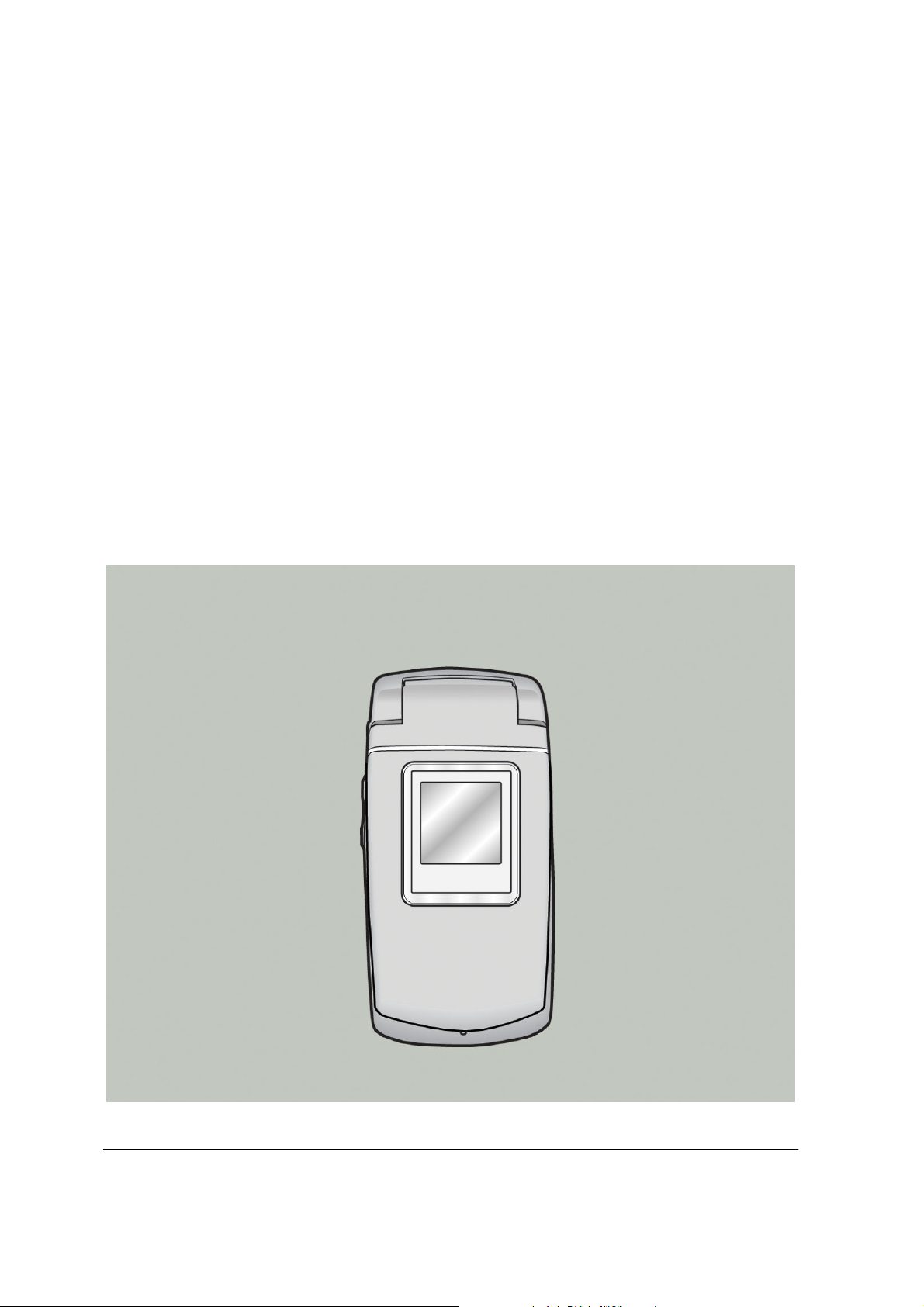
MODEL : V700
GPRS PHONE
SERVICE
MANUAL
I

Table Of Contents
1. Introduction ······································································································· 1-1
2. Specification······································································································ 2-1
2.1 H/W Features
2.2 S/W Features ······································································································2-2
·····································································································2-1
3. Disassembly Instruction··················································································· 3-1
3.1 Before Disassembly·······························································································3-1
3.2 Main Frame·········································································································3-2
3.3 Folder ················································································································3-3
3.4 Exploded View and Parts List ················································································· 3-5
3.4.1 Exploded View-Main ···················································································· 3-5
3.4.2 Exploded View-Folder···················································································3-7
3.4.3 Mechanical Parts List·····················································································3-8
4. Data Kit & Download Procedure ······································································ 4-1
4.1 Data Kit··············································································································4-1
4.1.1 Download Equipment ···················································································4-1
4.1.2 Download Procedure ····················································································4-1
5. Troubleshooting
5.1 Power-On Trouble ································································································5-1
5.2 MIC Trouble········································································································5-2
5.3 Receiver Trouble ··································································································5-3
5.4 Melody & MP3 Trouble(Handset speaker) ·································································5-4
5.5 LCD Trouble ·······································································································5-5
5.6 Charge Trouble ····································································································5-6
5.7 Vibrator Trouble ··································································································5-7
5.8 Key Backlight & Indicator Trouble ···········································································5-8
5.9 SIM Detection Trouble···························································································5-9
5.10 Ear Phone Receiver Trouble ················································································· 5-10
5.11 Camera Trouble································································································· 5-11
5.12 Ear Phone MP3 Trouble······················································································· 5-12
5.13 USB Mass Storage Trouble ··················································································· 5-13
5.14 BLUETOOTH Trouble ······················································································· 5-14
································································································ 5-1
II

5.15 TX Power Trouble(E-GSM)··················································································· 5-16
5.16 TX Power Trouble(DCS) ······················································································ 5-18
5.17 TX Power Trouble(PCS)······················································································· 5-20
5.18 RX Sensitivity Trouble(E-GSM)············································································· 5-22
5.19 RX Sensitivity Trouble(DCS) ················································································ 5-24
5.20 RX Sensitivity Trouble(DCS) ················································································ 5-26
6. Block Diagram
6.1 BB Block Diagram·································································································6-1
6.2 RF Block Diagram·································································································6-2
··································································································· 6-1
7. Schematic Diagram··························································································· 7-1
7.1 Key Pad··············································································································7-1
7.2 Main Board ·········································································································7-2
7.2.1 TI CHIPSET ································································································7-2
7.2.2 Memory ·····································································································7-3
7.2.3 Audio & MP3 ······························································································7-4
7.2.4 CONNECTOR ·····························································································7-5
7.2.5 Multimedia CHIPSET(Emblaze) ······································································7-6
7.2.6 Power Management & Charger ······································································· 7-7
7.2.7 CAMERA ···································································································7-8
7.3 RF Schematic·······································································································7-9
7.3.1 RF Pam
7.3.2 RF Main IC································································································ 7-10
······································································································7-9
8. PCB Diagram ····································································································· 8-1
8.1 Key PCB·············································································································8-1
8.2 Main PCB ···········································································································8-3
9. Part List·············································································································· 9-1
9.1 Electrical Part List(Circuit)······················································································9-1
9.1.1 Electrical Parts List (Main PCB) ·············································································9-1
9.1.2 Electrical Parts List (Key PCB) ············································································ 9-10
9.2 Mechanical Part List···························································································· 9-11
III

1. Introduction
This model is a Folder type mobile phone operated in the GPRS Digital Cellular Mobile Radio System,
which is the Pan-European mobile cellular standard. This model has the operation band of GSM 900
and DCS 1800 and PCS 1900. GPRS Class 10 II features are fully supported and parts of the GSM
Phase II+ features are also supported. About the SIM Toolkit, This model supports up to Class 3
including Class 1, 2. For speech communication, This model supports Full Rate(FR), Enhanced Full
Rate(EFR) and Half Rate(HR). For easy text, eZi Text is implemented and WAP protocol is adopted
for internet connection.
1-1

Introduction
Memo
1-2
2. Specification
2.1 HW Features
Item Description Remark
Supporting standard GSM 900/DCS 1800/PCS1900 Tri Band
E-GSM
Phase 2 and Phase 2+
SIM Toolkit : Class 1,2,3
GPRS Class 10
Frequency range
Battery
Display
Camera
Antenna Intenna type
PC synchronization Applied
Speech coding FR, EFR, HR
Data & Fax Built-in
E-GSM TX : 880 - 915 MHz
E-GSM RX : 925 - 960 MHz
DCS 1800 TX : 1710 - 1785 MHz
DCS 1800 RX : 1805 - 1880 MHz
PCS 1900 TX : 1850 - 1910 MHz
PCS 1900 RX : 1930 - 1990 MHz
Capacity
Standard : Li-ion, 830 mAh
Full graphic type
Dual LCD
Main 260k TFT Color LCD
Pixels : 176 x 220
Ext. 65k Color-STN LCD
Pixels : 96 x 96
CMOS type
2M Pixels, UXGA(1600*1200)
Vibrator Built-in
Dual Stereo Speaker Applied (64 poly Stereo Sound)
Portable Handsfree (Ear-Phone) Built-in
Travel charger Built-in
Bluetooth Built-in
USB USB 1.1
2-1
2.2 SW Features
Main menu Sub menu Detail item
Specification
Message
Write Message SMS/MMS
Inbox SMS/MMS
Outbox SMS/MMS
Draft SMS/MMS
Template
Info Message
Settings
Thank you very much!!
See you later.
Where are you?
When can we meet?
Please call me back.
Call Voice Mail Voice Mail
Voice Center
Read
Receive
Topics
Languages
Alert
SMS
Call Register
Call History
Call Duration
EMS
MMS
Memory Status
Missed No.
Received No.
Dialed No.
Last Incoming
Last Outgoing
Total Incoming
Total Outgoing
Reset
2-2
Specification
Main menu Sub menu Detail item
Call Register GPRS Counter
Profile
General
Silent
Vibration Only
Outdoor
Last Sent
Last Received
Total Sent
Total Received
Reset
Activate
Personalize
Rename
Activate
Personalize
Rename
Activate
Personalize
Rename
Activate
Personalize
Rename
Setting
Other 1
Other 2
Other 3
Alarm Set
Activate
Personalize
Rename
Activate
Personalize
Rename
Activate
Personalize
Rename
Time Set Time/Date Set
Date Set
Set Alarm
Alarm Sound
Power Off Alarm
2-3
Specification
Main menu Sub menu Detail item
Setting
Call Setting
Phone Setting
Security Setting
Call Divert
Call Waiting
Send My Caller ID
Answer Mode
Min Minder
Auto Redial
Auto Answer
Data Transfer Mode
Language
Main LCD
External Key
Key Back Light
Screen Saver
PIN Code
Phone Lock
Call Barring
Fixed Dial Number
Network Select
Bluetooth
Factory Set
Organizer Phonebook
Change Codes
Automatic
Manual
Preferred List
Discover
Paired Devices
Settings
Name Search
Group Search
Add Entry
Speed Dials
Caller Groups
PB Manage
2-4
Specification
Main menu Sub menu Detail item
Organizer
Camera
Scheduler
File Manager
Daily view
Weekly view
Monthly view
Make
Delete All
Setting
To Do
Memory Status
File List
Connect USB To Computer
Format Memory
Option Take Photo
Mode
Option Record Video
Mode
Internal Memory Photo Album
External Memory
Application
Phonebook Album
Configuration
Othello
Calculator
Unit Converter
Internal Memory Video Album
External Memory
View
Delete
Rename
Shutter Sound
Auto Save
Album Lock
Set Save Storage
Music Player MP3
Configuration
Length
Weight
2-5
Specification
Main menu Sub menu Detail item
Application
Unit Converter
Volumes
Surface
User Define
World Time
Voice Memo
Record
Play
Application Voice Memo Set Save Storage
Java
Downloads
Memory status
Network
APN
User Name
Password
Internet
Homepage
Add Bookmark Bookmarks
Create new folder
Recent Pages
Enter address
Resume
Settings
Push Inbox
SIM AT
Edit Homepage
Select Profile
Connection
Rename Profile
Cache
Clear Recent Page List
2-6
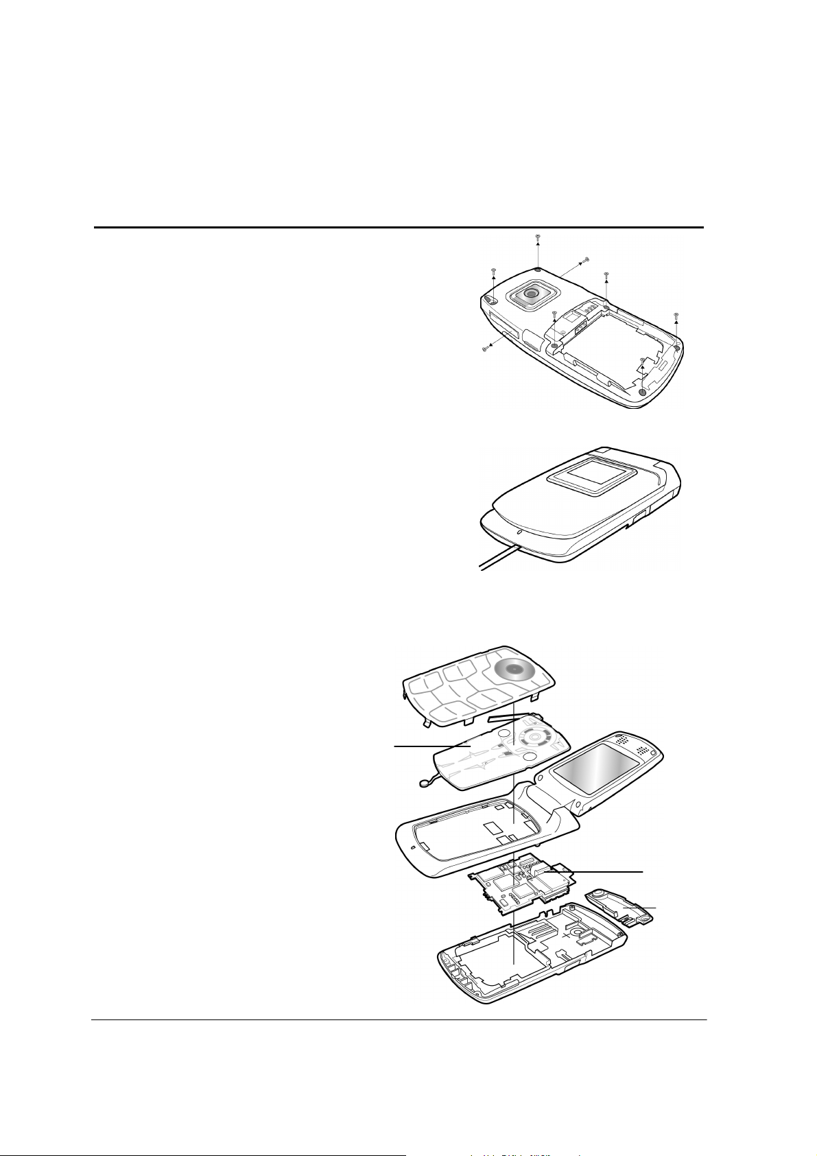
3. Disassembly Instruction
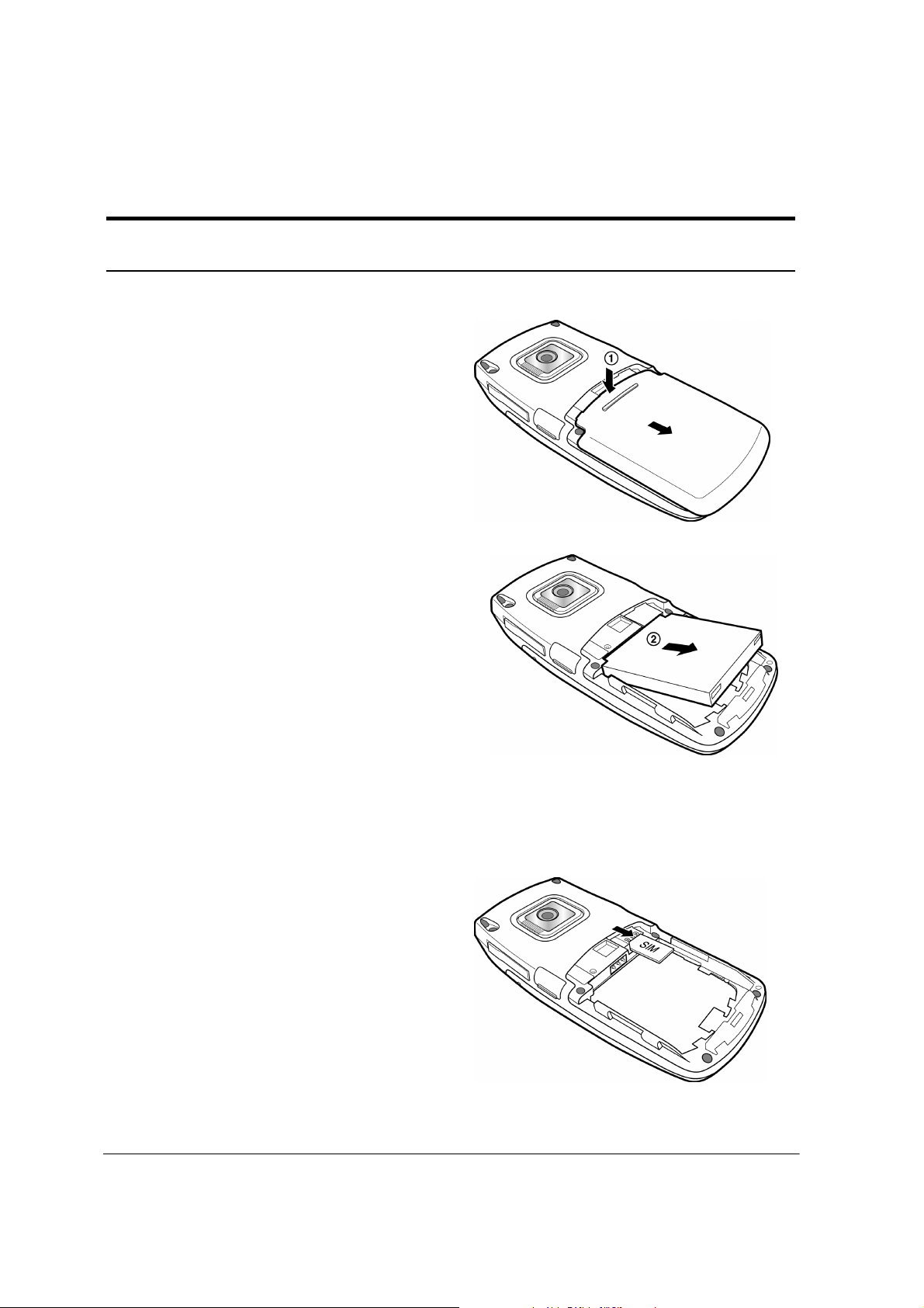
3.1 Before Disassembly
1. Remove the battery. To do so:
① Pull down the battery cover and open it.
② Lift up the battery and pull it out.
2. Remove the SIM card. To do so:
3-1
Intenna
Main PCB
3.2 Main Frame
1. Remove screws. To do so:
① Remove the Deco rear as shown.
② Remove Eight screws on the back of the phone.
2. Insert a small ‘ – ’ type driver between the front case
the rear case, and lift up the front case.
Disassembly Instruction
3. Now remove the rear case, intenna,
Main PCB and Key PCB in order.
Key PCB
3-2
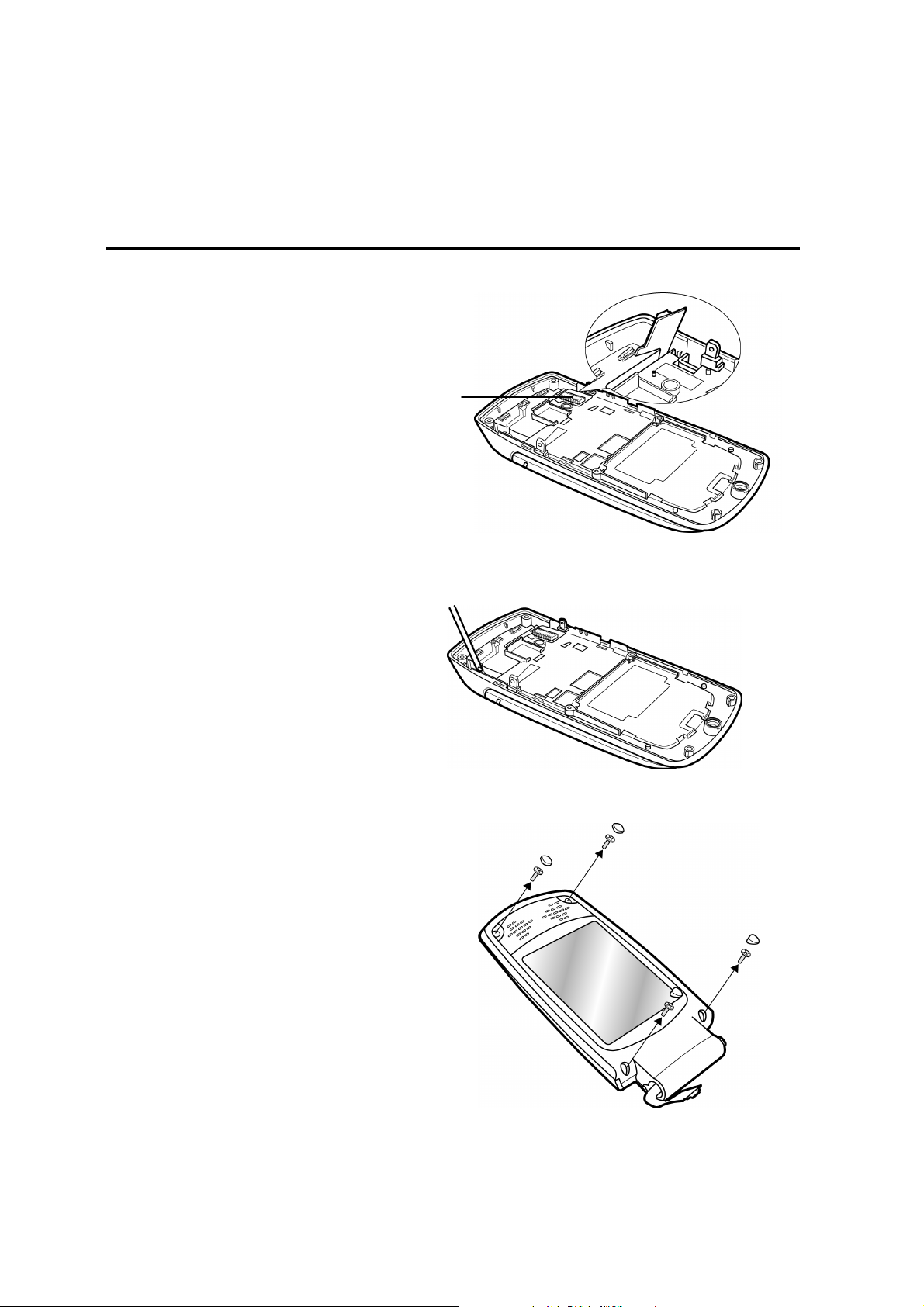
3.3 Folder
1. Remove the rear case as described at Steps 1 and 2
under Main Frame Disassembly on page 3-2.
2. Unplug the connector shown at the right side from
the main PCB.
3. Unhook the folder from the main frame.
Connector
Disassembly Instruction
4. Remove four screws from the folder.
3-3
D ass’y
upper
lower
5. Insert a small ‘ - ’ type driver between the folder
upper and the folder lower, and lift up the folder
upper.
Disassembly Instruction
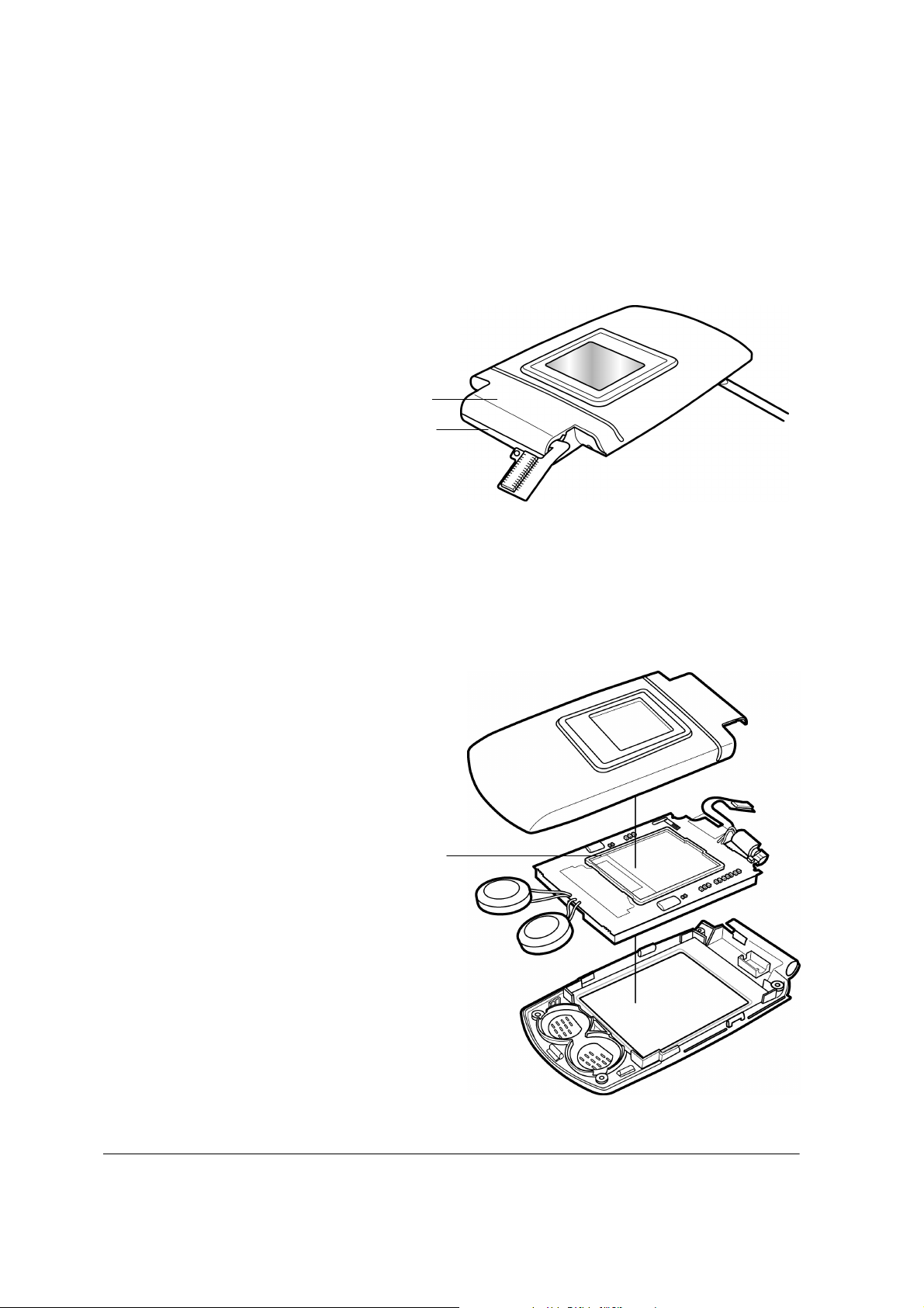
Folder
Folder
6. Now, you can remove the LCD ass’y and the other components.
LC
3-4
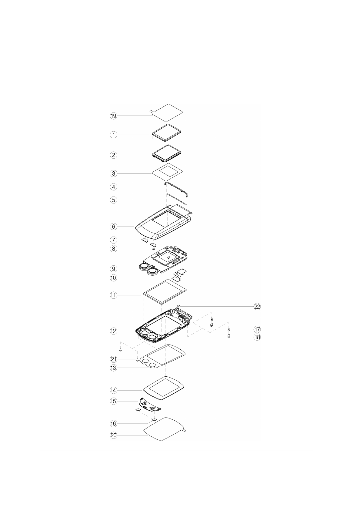
3.4 Exploded View and Parts List
3.4.1 Exploded View – Main
Disassembly Instruction
3-5
3.4.2 Exploded View – Folder
Disassembly Instruction
3-6

3.4.3 Mechanical Parts List
NO.
1
2
3
4
5
6
7
8
9
10
11
12
13
14
15
16
17
18
19
20
21
22
23
24
25
26
27
28
29
30
31
32
33
34
35
36
37
38
DESCRIPTION_ Main Q’TY NO.
KEY PAD
EL SHEET
KEY PCB ASS’Y
EMI TAPE - KEY PCB_1
RUBBER - DAMPER
RUBBER - STOPPER
HINGE
FRONT CASE
CAMERA MODULE
INTENNA
LCD ASS’Y
CUSHION - CAMERA
T-FLASH COVER
I/O COVER
CAMERA WINDOW
TAPE - CAMERA WINDOW
DECO – CAMERA
FLASH WINDOW
TAPE – FLASH WINDOW
RUBBER – R/F
REAR CASE
SCREW
BATTERY PACK ASS’Y
BATTERY COVER
LAXAN – FRONT
RUBBER – MIC
INSULATION TAPE – SIDE KEY
SHIELD FOAM – FRONT_2
INSULATION TAPE – KEYPAD
SIDE KEY
MAGNET
SHIELD FOAM – FRONT_1
DUMMY HINGE
EMI CUDHION & TAPE-I/O
EARJACK COVER
RUBBER SCREW MAIN
PROTECTION TPAE-CAMERA WINDOW
INSULATION TAPE – FRONT
Disassembly Instruction
DESCRIPTION- Folder Q’TY
1
1
DECO-SUB WINDOW
1
2
SUB WINDOW
1
3
CUSHION & TAPE-SUB WINDOW
1
4
DECO-FOLDER
2
5
TAPE-DECO FOLDER
1
6
FOLDER UPPER
1
7
CUSHION-SPEAKER
1
8
SHIELD FOAM-LCD
1
9
LCD MODULE ASS’Y
1
10
FPCB
1
11
CUSHION-MAIN WINDOW
1
12
FOLER LOWER
1
13
TAPE-MAIN WINDOW
1
14
MAIN WINDOW
1
15
DECO-SPEAKER
1
16
RUBBER - SCREW TOP
1
17
SCREW
1
18
RUBBER - SCREW BOTTOM
1
19
PROTECTION TAPE-SUB WINDOW
1
20
PROTECTION TAPE-MAIN WINDOW
1
21
SCREW-FOLDER
8
22
SHIELD FOAM- FPCB
1
1
1
1
1
1
3
1
1
1
1
1
1
1
1
2
1
1
1
1
1
1
2
2
1
1
1
1
1
1
1
2
2
2
1
1
2
1
3-7

4. Data Kit & Download Procedure
4.1 Data Kit
4.1.1 Download Equipment
Data Kit & Download Procedure
1. Download Cable
2. Desktop or Notebook PC
3. Download Fluid Program
4. Mobile Phone
4.1.2 Download Procedure
DOWNLOAD ENVIRONMENT
To download software of this model, the following environments should be
Prepared:
Download cable, Interface JIG, is connected to serial port of the desktop or notebook PC.
Download fluid program is copied to the desktop or notebook PC.
Target software is downloaded to this mobile phone.
Warning
You must use the download cable kit (Interface JIG) and UART download monitor program.
Otherwise, downloading process won't work properly.
4-1
Data Kit & Download Procedure
DOWNLOAD PROCEDURE
1. Unzip the model download fluid program (fluid2.11.zip) in the PC.
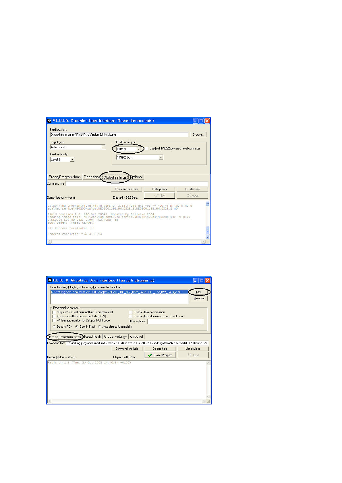
2. Execute fluid_gui.exe. And then select "Global settings" tab. Then choose a correct serial port in
the RS232 serial port Box. <Figure 1>
<Figure 1>
3. To download software, you must add the target software in the "Erase/Program flash" tab.
So, push the "Add" button, then choose the target software that you want to download.
<Figure 2>
4-2
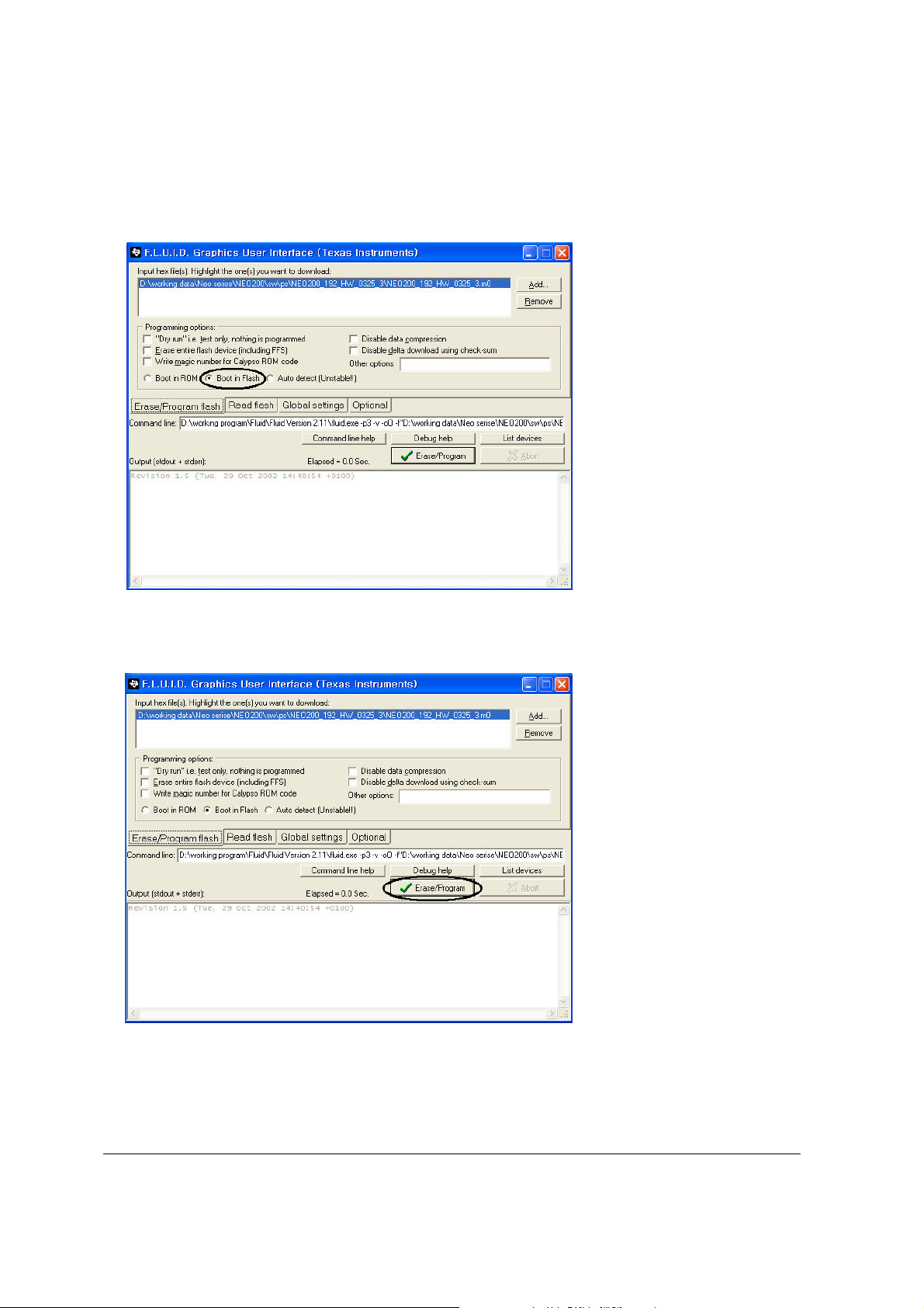
4. Select the "Boot in flash" in the "Programming options" box.
<Figure 3>
5. Push the "Erase/Program" button to download.
<Figure 4>
Data Kit & Download Procedure
4-3
Data Kit & Download Procedure
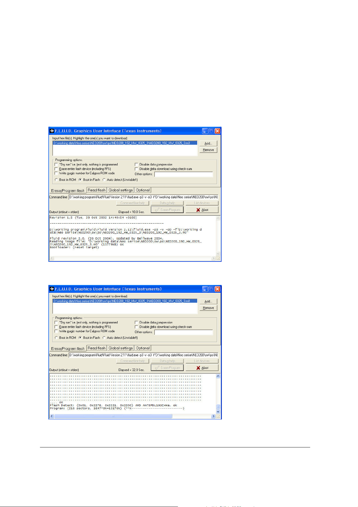
6. As the following window show in <Figure 5> is displayed, connect this phone to the download
cable, (Interface JIG) and press power on key of the phone. If the connection succeeded, the
following screen will show the contents as shown in <Figure 6>.
<Figure 5>
<Figure 6>
4-4
Data Kit & Download Procedure
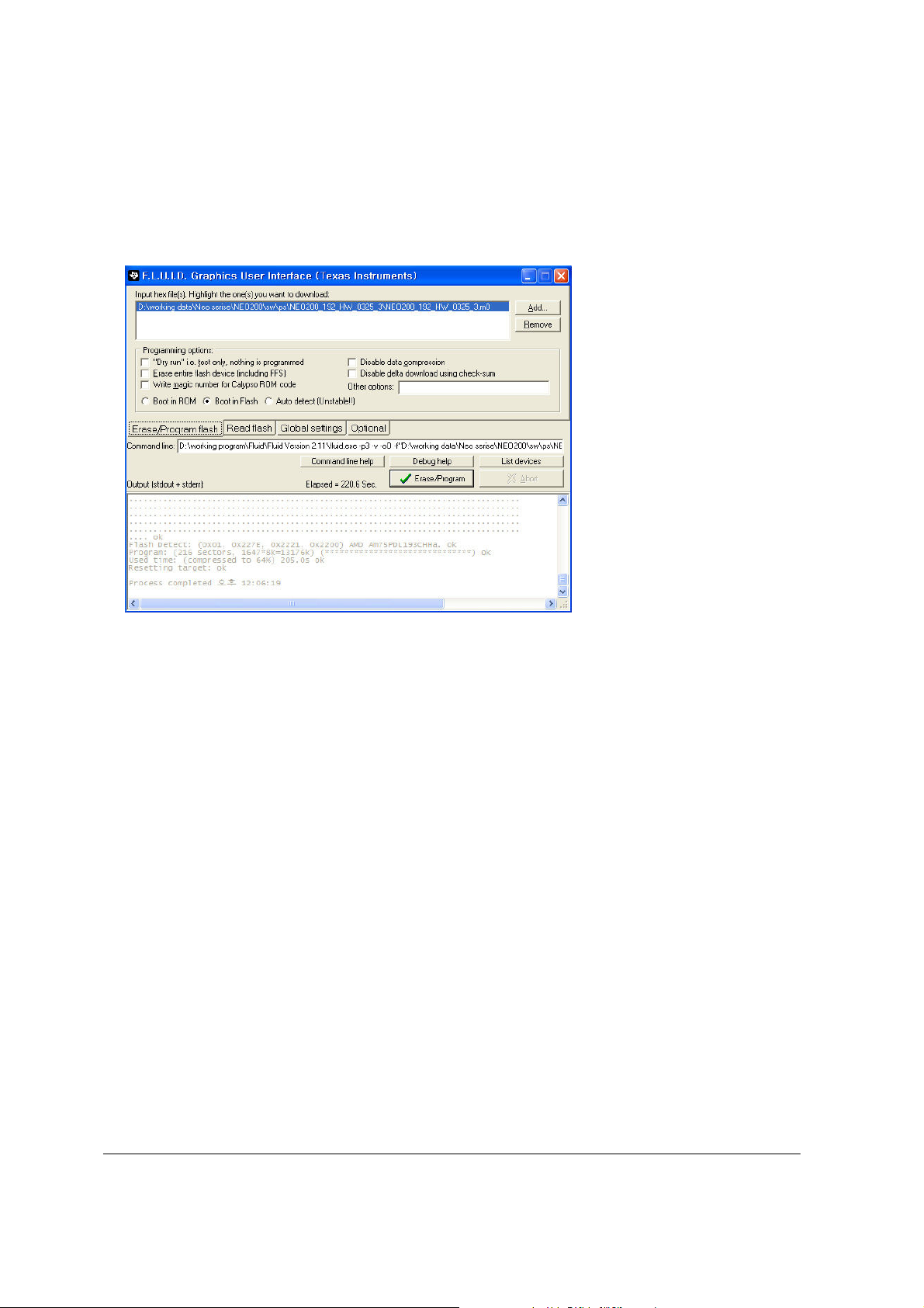
7. If the downloading procedure is succeeded, then the following window is shown.
<Figure 7>
4-5
5. Troubleshooting
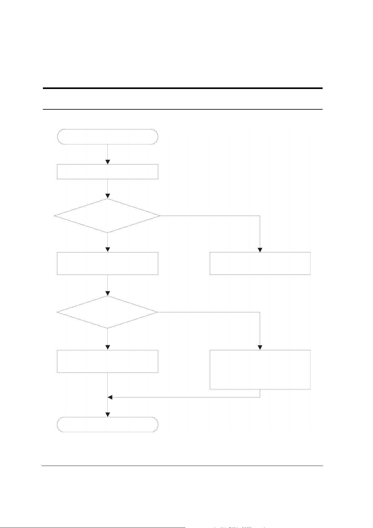
5.1 Power-on Trouble
Power-on button is not working.
Check the voltage level of battery.
The level of battery
voltage is higher
than 3.4V
YES
Check the level of TP520
(ON/OFF).
The level of TP520 as
high as 1.5V.
YES
Then the phone is powered-on
properly. Check the LCD module.
NO
Check the battery.
Charge the battery.
NO
Power-on sequence is not
executed properly. Try again.
If the result is same, change
U501 chipset.
END
5-1
 Loading...