

Voxtel BD38 Service Manual
GSM PHONE
SERVICE MANUAL
MODEL : BD38
1st version
(2004, 06, 09)

Rev. 1.00

I
Table Of Contents
1. Introduction ........................................................................................................ 1-1
2. Specification ....................................................................................................... 2-1
2.1 HW Features ................................................................................................................................................ 2-1
2.2 SW Features ................................................................................................................................................. 2-2
3. Disassembly Instruction ................................................................................................................ 3-1
3.1 Before Disassembly .................................................................................................................................... 3-1
3.2 Main Frame .................................................................................................................................................. 3-2
3.3 Folder ............................................................................................................................................................ 3-3
4. Data Kit & Download Procedure................................................................................................ 4-1
4.1 Data Kit ......................................................................................................................................................... 4-1
4.1.1 Download Equipment ....................................................................................................................... 4-1
4.1.2 Download Procedure ......................................................................................................................... 4-1
5. Troubleshooting.................................................................................................................................... 5-1
5.1 Power-On Trouble ....................................................................................................................................... 5-1
5.2 MIC Trouble ................................................................................................................................................. 5-2
5.3 Receiver Trouble .......................................................................................................................................... 5-3
5.4 Melody Trouble ........................................................................................................................................... 5-4
5.5 LCD Trouble ................................................................................................................................................ 5-5
5.6 Charge Trouble ............................................................................................................................................ 5-6
5.7 Vibrator Trouble .......................................................................................................................................... 5-7
5.8 Backlight Trouble ........................................................................................................................................ 5-8
5.9 TX Power Trouble (E-GSM)........................................................................................................................ 5-9
5.10 TX Power Trouble (DCS)......................................................................................................................... 5-11
5.11 Rx Sensitivity Trouble (E-GSM) ............................................................................................................ 5-13
5.12 Rx Sensitivity Trouble (DCS) ................................................................................................................. 5-15

II
Table of Contets
6. PCB Diagram ......................................................................................................................................... 6-1
6.1 Main PCB ...................................................................................................................................................... 6-1
7. Electrical Parts List ........................................................................................................................... 7-1
7.1 Main Parts List ............................................................................................................................................ 7-1
8. Exploded View and Parts List .................................................................................................... 8-1
8.1 Exploded View ............................................................................................................................................ 8-1
8.1.1 Main ...................................................................................................................................................... 8-1
8.1.2 Folder ................................................................................................................................................... 8-2
8.2 Mechanical Parts List ................................................................................................................................. 8-3
8.2.1 Main ...................................................................................................................................................... 8-3
8.2.2 Folder ................................................................................................................................................... 8-4
9. Block Diagram ...................................................................................................................................... 9-1
9.1 BB Block Diagram ....................................................................................................................................... 9-1
9.2 RF Block Diagram ....................................................................................................................................... 9-2
10. Schematic Diagram ...................................................................................................................... 10-1
10.1 Key Pad .................................................................................................................................................... 10-1
10.2 Main Board .............................................................................................................................................. 10-2
10.2.1 Chipset ............................................................................................................................................. 10-2
10.2.2 Memory & Melody ......................................................................................................................... 10-3
10.2.3 Audio & SIM ................................................................................................................................... 10-4
10.2.4 Connector ........................................................................................................................................ 10-5
10. 3 RF Top Schematic ................................................................................................................................... 10-6
10.3.1 RF PAM ............................................................................................................................................ 10-6
10.3.2 RF Main IC ...................................................................................................................................... 10-7

1. Introduction
BD38 is a folder type mobile phone operated in the GSM Digital Cellular Mobile Radio System, which is the
Pan-European mobile cellular standard. BD38 has the operation band of GSM 900 and DCS 1800. GSM Phase II
features are fully supported and parts of the GSM Phase II+ features are also supported. About the SIM Toolkit,
BD38 supports up to Class 3 including Class 1, 2. For speech communication, BD38 supports Full Rate(FR),
Enhanced Full Rate(EFR) and Half Rate(HR). For easy text, eZi Text is implemented.
1-1

2. Specification
2.1 HW Features
Item Description Remark
Supporting standard GSM 900/DCS 1800 Dual Band
E-GSM
Phase 2 and Phase 2+
SIM Toolkit : Class 1, 2
Frequency range E-GSM TX : 880 - 915 MHz
E-GSM RX : 925 - 960 MHz
DCS 1800 TX : 1710 - 1785 MHz
DCS 1800 RX : 1805 - 1880 MHz
Battery Capacity
Standard : Li-ion, 720 mAh
Display 1. Full graphic type
2. Single LCD
3. Main LCD
65,000 color UFB STN LCD
Pixels: 128x160
Antenna Intenna type
PC synchronization Applied
Speech coding FR, EFR, HR
Data & Fax Built-in
Vibrator Built-in
Dual Speaker Built-in
Portable Handsfree (Ear-Phone) Built-in
Travel charger Built-in
2-1

2-2
Specification
2.2 SW Features
Function Detail Item Comments
Normal features Last dialed number 20 entry
Last received number 20 entry
Last missed number 20 entry
Scratch pad memory 1
Call Call waiting Yes(network dependent)
Call multiparty Yes(network dependent)
Call Hold Yes(network dependent)
Call Retrieve Yes(network dependent)
Call Swap Yes(network dependent)
Audio Earpiece volume 5 level
Mute on& Mute off Yes
Cell broadcast CB option On / Off
Read topics SIM / Phone
Languages Same as number of language
Voice memo Voice recording 30 sec (15 sec x 2 entry)
Play
Delete All
Supplementary services Call barring All outgoing calls
All outgoing international calls
All outgoing int. calls except to home country
All incoming calls when roaming
Call Forward Always
Busy
No Reply
Unreach
Short Message Write message Send/Store
Output message Send/Save/Extract Number/
Delete/Delete All
Input message Reply/Forward/Edit/Extract number/
Delete/Delete All
Status report Delete/Delete All
Call voicemail
CB Option(On/Off)/Read
Topics(SIM/Phone)/Languages

2-3
Specification
Function Detail Item Comments
Memory Status
Message set Status report
Expiry period/SMS center
Voice center/Alert
Multi-band Support of multi-band & mode GSM 900
EGSM
DCS1800
Miscellaneous function Development & test facility
Field test facility
Display software version
Text input Language English
eZi text Predictive word input
Scheduler View day
View Monthly
View Weekly
Make Meet
Birthday
Anniversary
Memo
Call
Delete
Find
Setup
World time Setting local time
Number of selectable cities 28 Cities
Calculator Operator Addition
Subtraction
Multiplication
Division
Unit converter Length conversion
Weight conversion
Volumes conversion
Surface conversion
User define
Counter Count Key Numeric key 1 to 9

2-4
Specification
Function Detail Item Comments
Melody Composer Compose 4 Poly
Melody List 10
Delete All
Volume 1~5
Bio Rhythm My Rhythm
Friend Rhythm
Special day
Setup My Birthday
Friend’s Birthday
Game 2EA Mobile Soccer
Magic Hunter
3. Disassembly Instruction
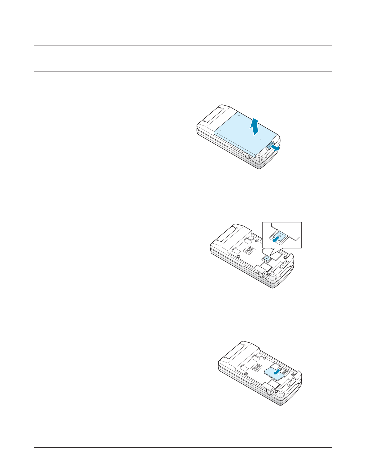
3.1 Before Disassembly
② Remove the SIM card as shown.
3-1
①
②
2. Remove the SIM card. To do so:
① Slide the metal lock in the direction of arrow.
1. Remove the battery. To do so:
① Pull the battery lock below the battery.
② Lift the battery away.
3-2
Disassembly Instruction
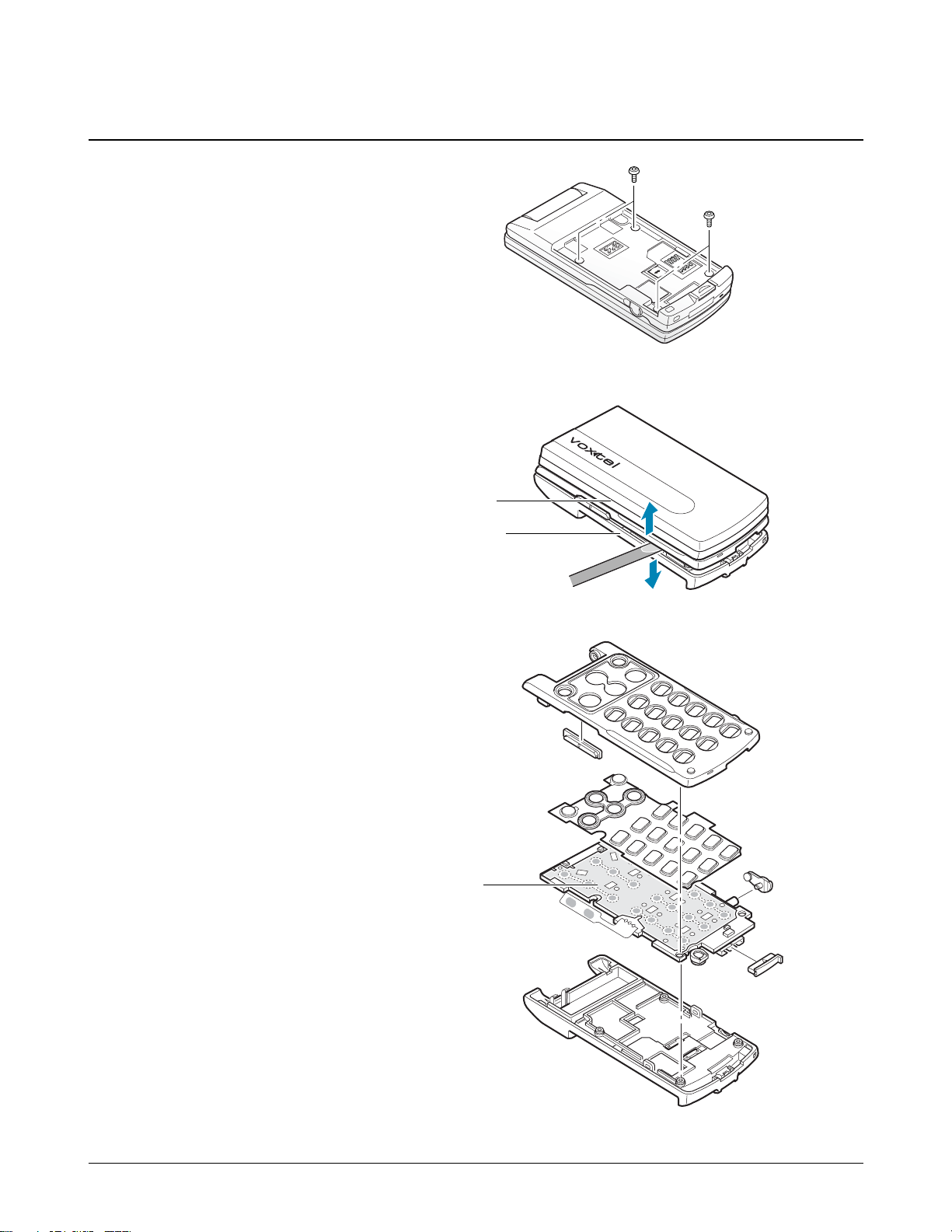
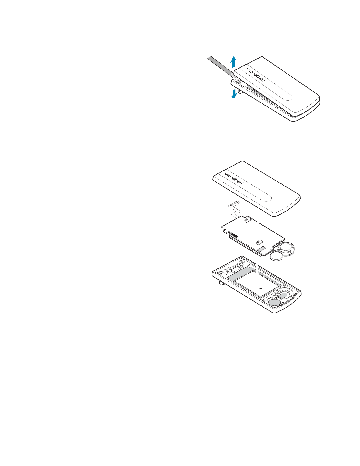
3.2 Main Frame
1. Remove the four screws on the back of the phone.
2. Insert a small ‘ - ‘ type driver between the front case
and the Rear case, and lift up the front case.
Front case
Rear case
Main PCB
3. Now, you can replace the PCBs and the other
components.
3-3
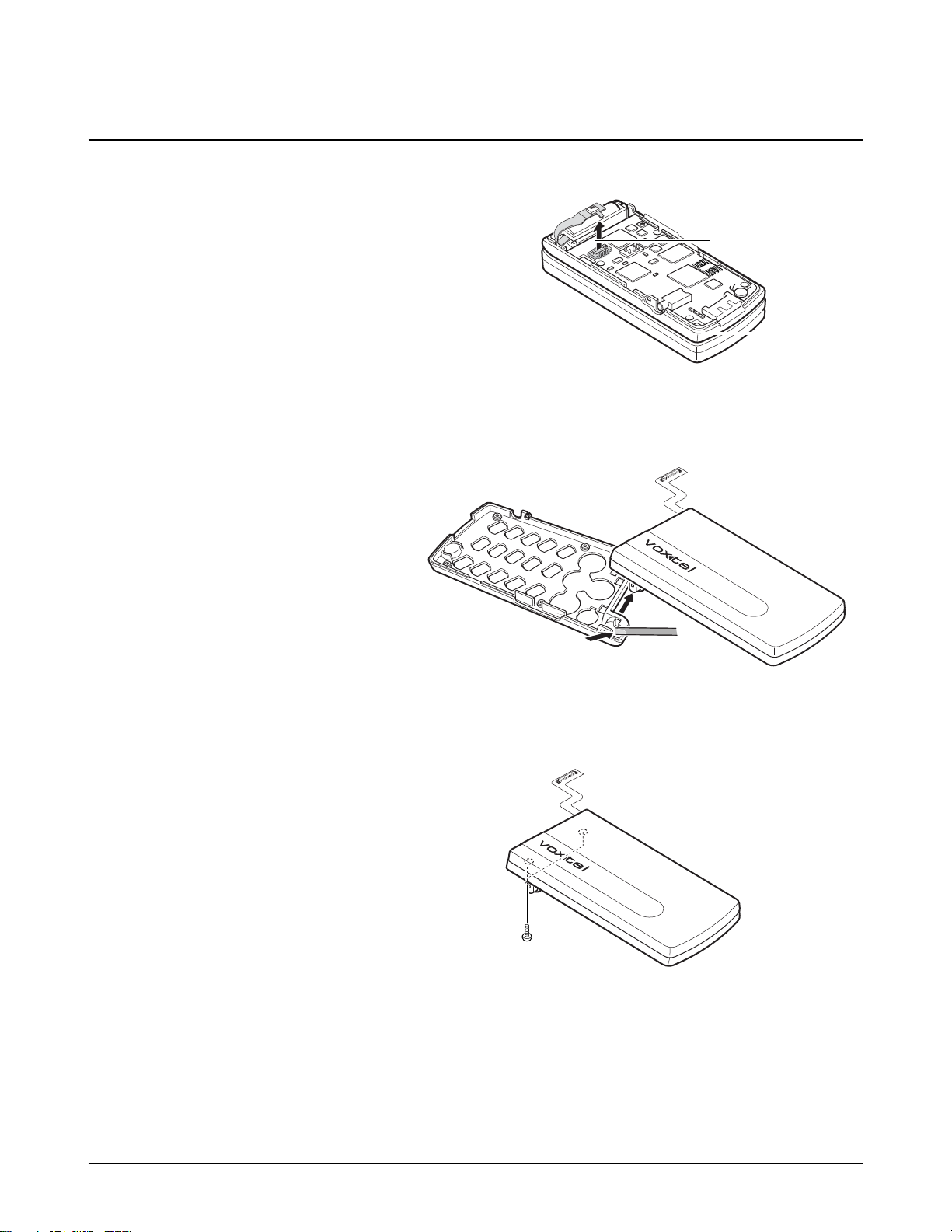
Disassembly Instruction
1. Remove the back case as described at Steps 1 and 2
under Main Frame Disassembly on page 3-2.
2. Unplug the connector from the main PCB as shown.
3. Unhook the folder from the main
frame.
3.3 Folder
4. Remove the two screws from the folder.
Connector
Main PCB
3-4
Disassembly Instruction
6. Now, you can remove the LCD ass’y and the other
components.
LCD ass’y
5. Insert a small ‘ - ‘ type driver between the folder
upper and the folder lower, and lift up the folder
upper.
Folder upper
Folder lower

4. Data Kit & Download Procedure
4.1 Data Kit
4.1.1 Download Equipment
1. Data kit
2. Desktop or Notebook PC
3. Download monitor program
4. BD38 mobile phone
4.1.2 Download Procedure
DOWNLOAD ENVIRONMENT
To download software of BD38, the following working environments should be
prepared:
• BD38 data link kit, LC-100, is connected to COM1 or COM2 serial port of the desktop or notebook PC.
• BD38 data kit download monitor program is copied to the desktop PC or notebook PC.
• Target software is downloaded to the BD38 mobile phone.
Warning
You MUST use the data link kit (LC-100) and UART download monitor program. Otherwise, downloading
process won’t work properly.
4-1
4-2
DO
WNLOAD PROCEDURE
1. Unzip BD38 UART Download monitor program (monitor670.zip) in the PC.
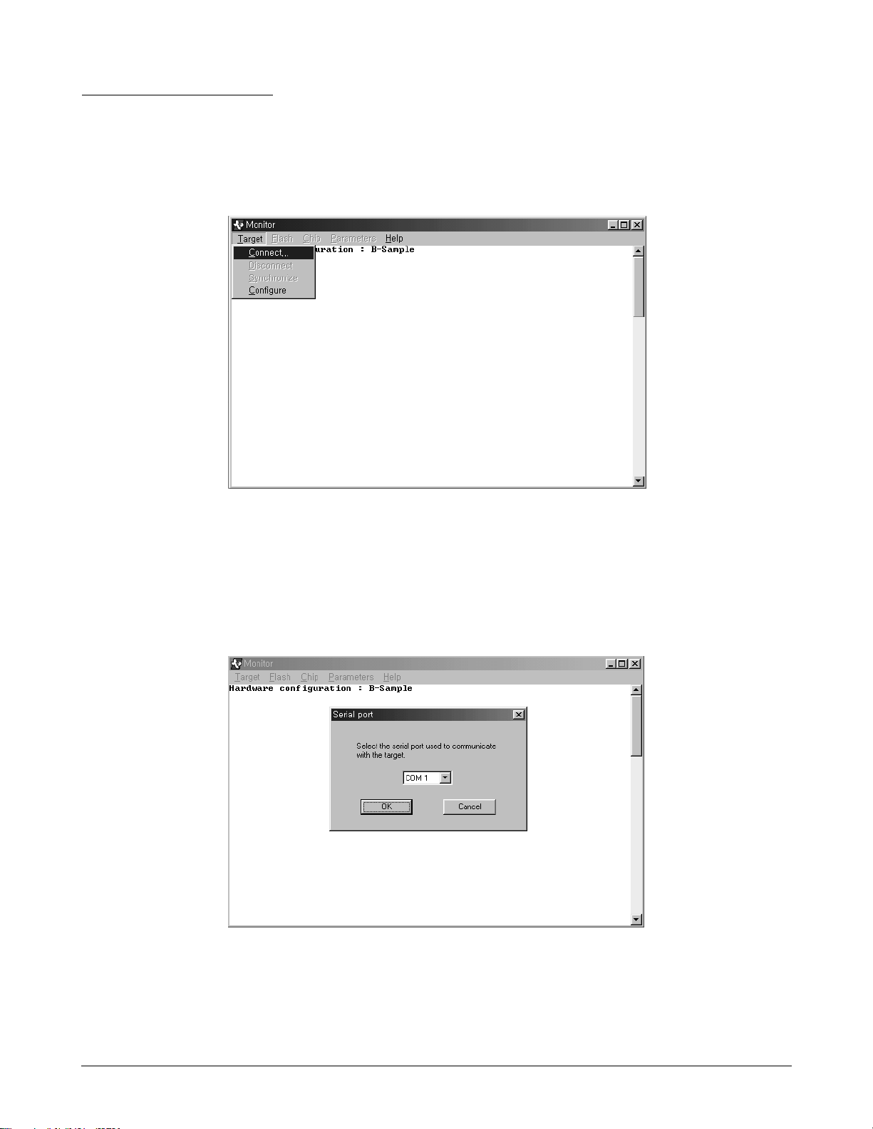
2. Execute monitor670.exe. And then select Target menu. Then, choose Connect from the Target menu.
3. A table will be displayed as shown in <Figure 2>. Then press the arrow-button and choose a correct serial
port. And press OK button.
Data Kit & Download Procedure
<Figure 1>
<Figure 2>
4-3
Data Kit & Download Procedure
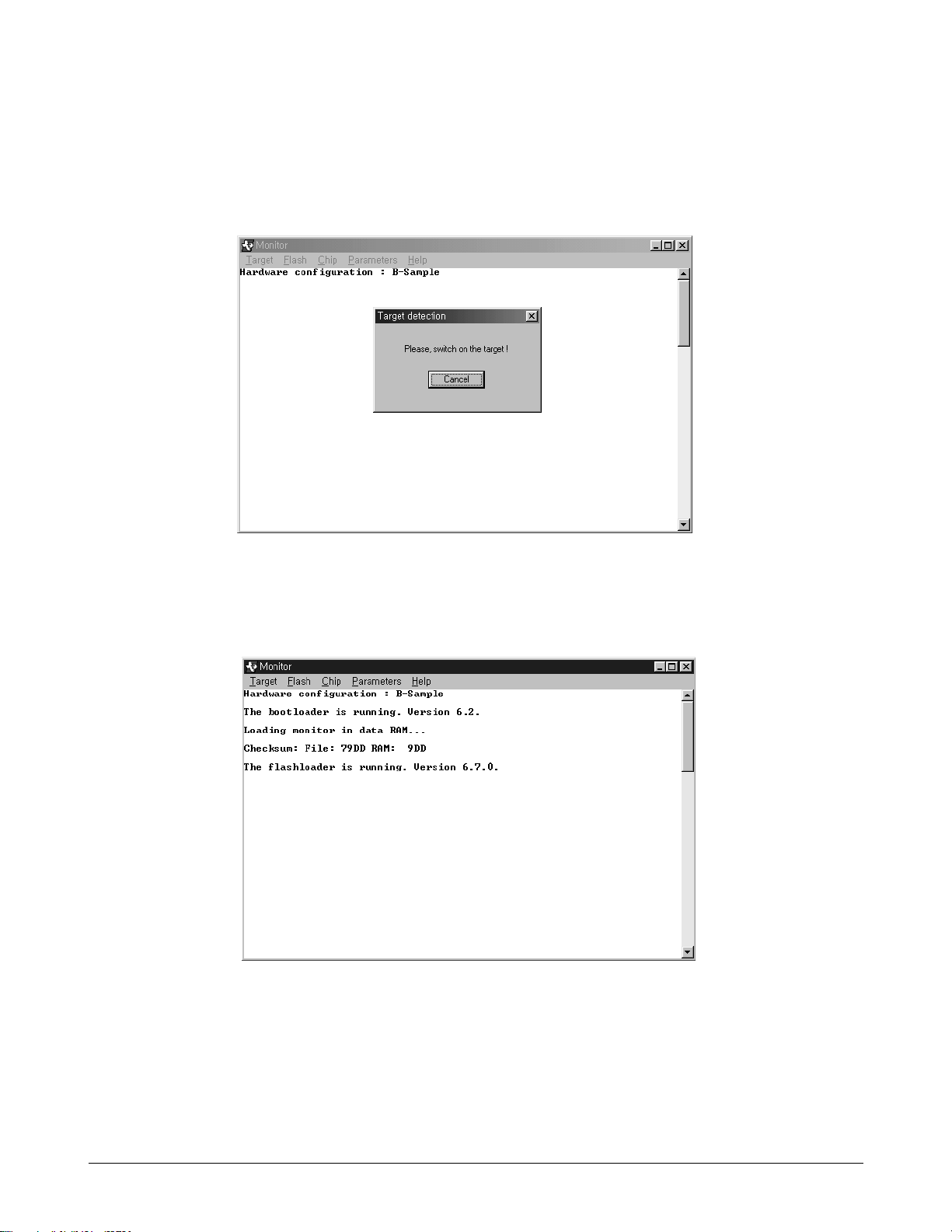
4. As the following window shown in <Figure 3> is displayed, connect BD38 phone to the data link kit, (LC-
100) and power on BD38. If the connection is succeeded, the following screen will show the contents as
shown in <Figure 4>.
<Figure 3>
<Figure 4>
4-4
Data Kit & Download Procedure
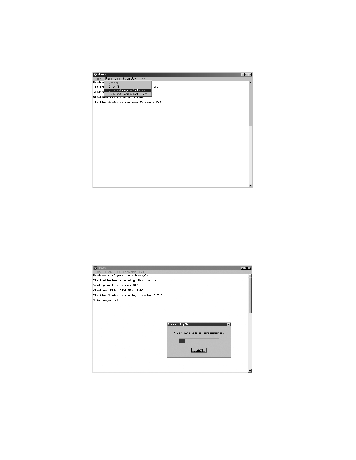
5. Click on Flash on the top menu and select Erase and Program Appli only item as shown in <Figure 5>.
6. Choose the target SW that you want to download. And then you can see the following window in
<Fingure 6>.
<Figure 5>
<Figure 6>
 Loading...