

Page 1

Workshop Manual
A
Group 20-26
2(0)
D3-D/E/F
Page 2

Page 3

Content
General Information
00-0 General ................................................................................................ 3
Specifications
03-2 Specifications, Engine ....................................................................... 9
Safety and Other Instructions
05-1 Safety Instructions ........................................................................... 13
Special tools
08-2 Special Service Tools ....................................................................... 17
General
20-0 Engine Information, General ............................................................
Design and Function ................................................................................ 22
Engine
21-0 Engine Complete, General ............................................................... 25
Engine Assembly ...................................................................................... 44
21-1 Cylinder Head .................................................................................... 45
21-5 Timing Gears and Shaft ................................................................... 72
21-6 Crank Mechanism ............................................................................. 80
19
Lubricating and Oil System
22-0 Lubricating and Oil System, General .............................................. 87
22-1 Oil pump and Line ............................................................................ 89
22-3 Oil cooler ........................................................................................... 91
Fuel System
23-3 Fuel Feed Pump and Filter ............................................................... 92
23-6 Injection Pump, Regulator ............................................................... 99
23-7 Injectors and Delivery Pipes .......................................................... 101
Inlet and Exhaust System
25-1 Inlet and Exhaust Manifolds .......................................................... 111
25-5 Turbo and supercharger ................................................................ 115
25-6 Air Cleaner, Throttle Housing ........................................................ 120
Cooling System
26-0 Cooling System, General ............................................................... 121
26-1 Radiator, Heat Exchanger .............................................................. 123
26-2 Coolant Pump, Thermostat ............................................................ 128
26-5 Charge Air Cooler with Connections ............................................ 132
26-6 Sea Water System, Sea Water Pump ............................................ 137
Alternator, Charge Regulator
32-1 Alternator ......................................................................................... 141
Starting System
33-1 Starter Motor ................................................................................... 143
Other Electrical Equipment
36-6 Monitoring and Control Systems .................................................. 145
Cables and fuses
Page 4

37-1 Cables .............................................................................................. 146
Instruments
38-6 Sensors for Indicator and Warning System ................................. 154
Steering
64-5 Power Steering ................................................................................ 160
Alphabetical index .................................................................................. 163
References to Service Bulletins ............................................................ 165
2 47702022 12-2011
Page 5

00-0 General
About this Workshop manual
General information
Service Manual contains technical data, descrip-
This
tions and maintenance and repair instructions for
standard model Volvo Penta products. A list of these
products may be found in the section Specifica-
tions.
The product designation and the serial number and
specification is indicated on the engine decal or type
plate. This information must be included in all correspondence regarding the product.
The service manual is produced primarily for the use
of Volvo Penta workshops and their qualified personnel. It is assumed that any person using the Service
Manual has a fundamental knowledge of the product
and is able to carry out mechanical and electrical
work to trade standard.
Volvo Penta continually develops its products; we
therefore reserve the right to make changes. All information in this manual is based on product data which
was available up to the date on which the manual was
printed. New working methods and significant
changes introduced to the product after this date are
communicated in the form of Service bulletins.
Spare Parts
Spare parts for the electrical and fuel systems are
subject to various national safety standards. Volvo
Penta Original Spare Parts meet these standards. No
damage of any kind caused by the use of spare parts
not approved by Volvo Penta will be compensated by
any warranty undertaking.
Certified engines
When carrying out service and repair on emission-certified
of the following:
Certification means that an engine type has been
inspected and approved by the relevant authority.
The engine manufacturer guarantees that all engines
of the same type are manufactured to correspond to
the certified engine.
This places special demands on service and repair
work, namely:
• Maintenance and service intervals recommended by Volvo Penta must be complied with.
• Only spare parts approved by Volvo Penta may
be used.
• Service on injection pumps, pump settings and
injectors must always be carried out by an
authorized Volvo Penta workshop.
• The engine must not be converted or modified,
except with accessories and service kits which
Volvo Penta has approved for the engine.
• No changes to the exhaust pipe and engine air
inlet duct installations may be made.
• No warranty seals (where present on the product) may be broken by unauthorized persons.
The general instructions in the Operator's Manual
concerning operation, service and maintenance
apply.
IMPORTANT!
Neglected or poorly-performed care/service and the
use of spare parts not approved by Volvo Penta, will
mean that AB Volvo Penta no longer guarantees that
the engine conforms to the certified model.
engines, it is important to be aware
Volvo Penta accepts no responsibility for damage or
costs arising as a result of failure to follow the above
mentioned standards.
47702022 12-2011 3
Page 6

!
!
!
00-0 General
Repair instructions
Introduction
The working methods described in this manual are
based on a workshop scenario where the product is
mounted in a holding fixture. Maintenance work is
carried out in situ, in which case – if nothing else
often
is indicated – using the same working methods as the
workshop.
Warning symbols that occur in the service manual.
For significance, refer to Safety Information .
DANGER!
WARNING!
CAUTION!
IMPORTANT!, NOTICE!
by no means comprehensive since not everything
are
can be foreseen as service work is carried out in the
most varied of circumstances. We call attention to
risks that may occur due to incorrect handling during
work in a well-equipped workshop using working
methods and tools tried and tested by us.
The service manual describes work operations carried out with the aid of Volvo Penta Special Tools,
where such have been developed. Volvo Penta Special Tools are designed to ensure the safest and most
rational working methods possible. It is therefore the
responsibility of anyone using tools or working methods other than those we recommend to ensure that
no risk of personal injury or mechanical damage is
present, or that malfunction can result.
In some cases, special safety regulations and user
instructions may be in force for the tools and chemicals mentioned in the Service Manual. These regulations must always be followed, and no special
instructions regarding this are to be found in the Service Manual.
By taking these basic precautions and using common
sense it will be possible to guard against most elements of risk. A clean workplace and a clean product
will eliminate many risks of personal injury and malfunction.
Our mutual responsibility
product comprises a large number of interacting
Each
systems and components. A deviation from the technical specification may dramatically increase the
environmental impact of an otherwise reliable system. It is therefore critical that the stated wear tolerances be adhered to, that systems which can be
adjusted be correctly set up and that only Volvo Penta
Original Parts are used. The intervals in the care and
maintenance schedule must be followed.
Some systems, e.g. fuel systems, often require special expertise and test equipment. A number of components are factory-sealed, for among other things
environmental reasons. Warranty-sealed components may not be worked on without authorization to
perform such work.
Remember that most chemical products, incorrectly
used, are harmful to the environment. Volvo Penta
recommends the use of biodegradable degreasers
whenever components are cleaned, unless otherwise
specified in the Service Manual. When working outdoors, take especial care to ensure that oils and wash
residues etc. are correctly properly for destruction.
Tightening torques
Tightening torques for vital fasteners that must be
applied using a torque wrench are indicated in the
Service Manual, chapter Tightening torques and in
the Manual's work descriptions. All torque indications
apply to clean threads, bolt heads and mating faces.
Indicated torque data apply to lightly-oiled or dry
threads. If lubricants, locking fluids or sealants are
required for fasteners, the correct type will be noted
in the job description.
Torque, angle tightening
When torque/angle tightening, the fastener is tightened to a specified torque, and tightening then continues through a pre-determined angle.
Example: For 90° angle tightening, the fastener is
turned a further 1/4 turn in one sequence, after the
specified tightening torque has been achieved.
Above all, when working on fuel systems, hydraulic
systems, lubrication systems, turbochargers, inlet
systems, bearings and seals, it is of the utmost importance that dirt and foreign objects are kept away, as
malfunctions or shortened service intervals may otherwise result.
4 47702022 12-2011
Page 7
00-0 General
Lock nuts
Removed
replaced by new ones, as locking properties are
impaired or lost with re-use.
In the case of lock nuts with plastic inserts the tightening torque indicated must be reduced if the nut has
the same nut height as a standard, all-metal hexagonal nut.
Reduce the torque by 25% for bolt sizes of 8 mm or
larger.
In the case of lock nuts with plastic inserts with a high
nut-height (where the all-metal thread is as high as a
standard hexagonal nut), the indicated torque
applies.
locknuts may not be re-used; they must be
Strength classes
Nuts and bolts are subdivided into different strength
classes. The classification is shown by a marking on
the bolt head. Markings of a higher number indicate
stronger material. For example, a bolt marked 10-9 is
stronger than one marked 8-8.
For this reason, it is important that when bolts are
removed they are returned to their original locations
on re-assembly. When replacing bolts check the
applicable Spare parts catalogue to ensure the cor-
rect bolt is used.
Sealing compounds etc.
Anaerobic agents.
These agents cure (harden) in the absence of air.
These
nents, e.g. two cast components, are fitted together
without a gasket. Common uses are also to lock and
seal plugs, stud threads, taps, oil pressure monitors
etc.
Hardened anaerobic preparations are glassy and for
this reason, the preparations are colored to make
them visible. Hardened anaerobic preparations are
highly resistant to solvents, and old compound cannot be removed. On re-assembly, it is important to
carefully degrease and wipe dry components first,
before applying new sealant in accordance with the
instructions.
preparations are used when two solid compo-
Safety regulations for fluorocarbon
rubber
Fluorocarbon rubber is a common material in sealing
rings for shafts, and in O-rings, for example.
When fluorocarbon rubber is exposed to high temperatures (above 300°C/572°F), hydrofluoric acid
can form. This is highly corrosive. Contact with the
skin can result in severe chemical burns. Splashes in
your eyes can result in chemical wounds. If you
breathe in the fumes, your lungs can be permanently
damaged.
To ensure service work is correctly carried out it is
important that the correct type of sealants and locking
fluids are used on joints where such are required.
In each service manual section concerned, the sealants used in product manufacture are indicated. The
same sealants, or sealants with equivalent properties, must be used for maintenance work.
Make sure that mating surfaces are dry and free from
oil, grease, paint and anti-corrosion agent before
applying sealant or locking fluid. Always follow the
manufacturer's instructions regarding applicable
temperatures, hardening times and such.
Two basic types of compound are used:
RTV preparations (Room Temperature Vulcanizing).
Used most often together with gaskets, e.g. sealing
gasket joints, or are brushed on gaskets. RTV sealants are completely visible when the part has been
removed. Old RTV sealant must be removed before
the component is sealed again. Use denatured alcohol.
WARNING!
Seals must never be cut with a torch, or be burnt
afterwards in an uncontrolled manner. Risk for
poisonous gases.
WARNING!
Always use chloroprene rubber gloves (gloves for
chemicals handling) and goggles. Handle the
removed seal in the same way as corrosive acid. All
residue,
use compressed air to blow clean.
Put the remains in a plastic container, seal it and
apply a warning label. Wash the gloves under running
water before removing them.
The following seals are most probably made from fluorocarbon rubber:
Seal rings for the crankshaft, camshaft, idler shafts.
O-rings, regardless of where they are installed. Orings for cylinder liner sealing are almost always
made of fluorocarbon rubber.
Please note that seals which have not been
exposed to high temperature can be handled normally.
including ash, can be highly corrosive. Never
47702022 12-2011 5
Page 8
00-0 General
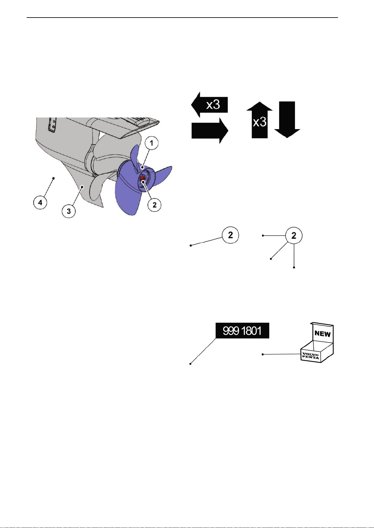
Illustrations
A lot of illustrations contains standardized symbols and colors. Please refer to the following information to reduce
misunderstandings when working on an engine / transmission using this Workshop Manual.
Illustration colors
Most illustrations have a focused component (blue)
which is fastened by a (red) bolt or such on a (light
grey) engine / transmission body.
P0015699
1
Focus
(blue)
2 Fastenings
(red)
Position
P0015623
Focus arrows pointing at object. Sometimes it contains number of items, e.g. three bolts.
NOTICE! If an arrow with the text “x3” is pointing at
only one item, e.g. a bolt, it still applies to the other
two
alike items (the two other bolts) highlighted in the
illustration.
3 Body
(light grey)
4 Background
(white)
P0015627
This symbol gives a positioning number to an object,
e.g. 2, which is also mentioned in the supplied text
information.
P0015628
The
symbol to the left shows part no. of the positioned
special tool, e.g. 9991801.
The symbol on the right side is used when something
needs to be replaced by a new part / kit.
6 47702022 12-2011
Page 9
00-0 General
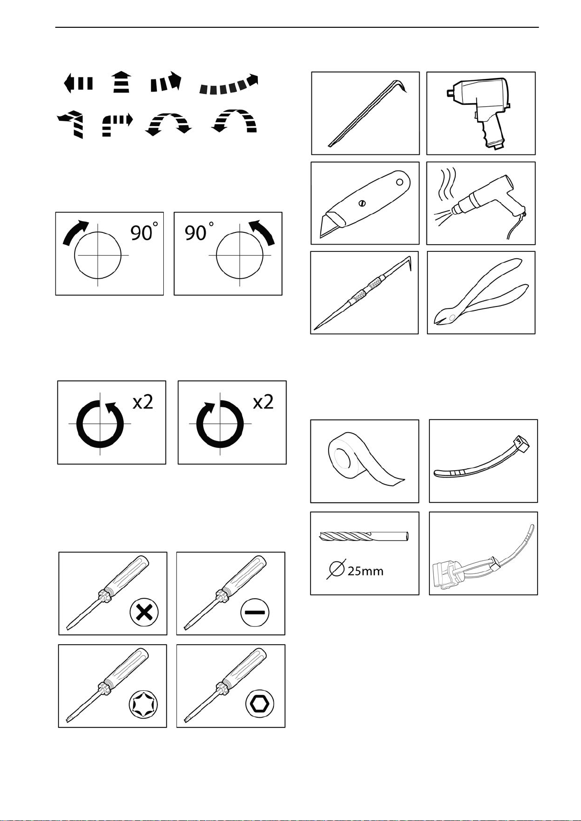
Movement
P0015622
Movement
component is to be moved / rotated.
P0015625
Symbol is used in a corner of the illustration to show
how many degrees the object shall be turned and at
which direction.
arrows are used to show which direction a
Tools (continuence)
P0015630
A symbol of a tool in a corner of the illustration is
shown when the tool is recommended to use, e.g. a
knife or a crowbar.
P0015626
Symbol is used to show how many revolutions the
object shall be turned and at which direction.
Tools
P0015629
One
of the following symbols is used when describing
the recommended type of screwdriver.
P0015631
A drill in a specified size, duck tape and stripes may
also be shown as symbols.
47702022 12-2011 7
Page 10
00-0 General
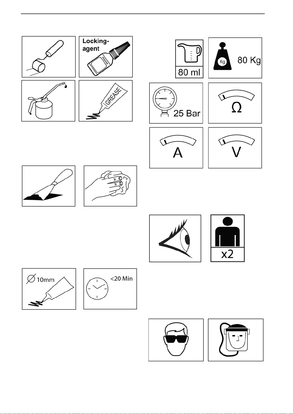
Chemicals
P0015695
Symbols
can also describe when and how a chemical
product is to be used.
Cleanliness
Units
P0015624
The scraper symbol suggests that a contact surface
needs to be scraped from sealant etc.
The cloth symbol suggests that the mechanic should
clean the contact surface thoroughly or be prepared
for some oil spill or similar.
Sealant
P0015698
P0015696
Units
are mentioned in the illustration when a specific
value (e.g. pressure, weight or resistance etc.) is
expected.
Important
P0015005
The
eye symbol is used when something needs close
inspection or must be performed in a certain way.
The symbol to the right is used when several mechanics are needed.
Safety
The tube symbol shows how thick layer of sealant to
applicate.
The clock symbol is used when something needs to
be done within or after a certain time.
P0015697
symbols are used when a certain safety related
These
equipment is needed.
8 47702022 12-2011
Page 11
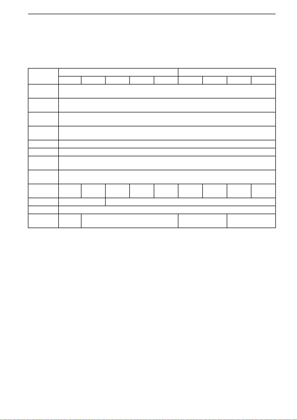
03-2 Specifications, Engine
Technical Data
Engine, General
Inboard Aquamatic
D3-110 I D3-150 I D3-170 I D3-200 I D3-220 I D3-140 D3-170 D3-200 D3-220
No. of cylinders
No. of
valves
Displacement
Firing
sequence
Bore 81 mm (3.19")
Stroke 93.2 mm (3.67")
Compression ratio
Idling
speed
Engine
power
High idle 3000 rpm 4000 rpm
Rating 5
Transmission
81 kW
(110 hp)
HS25 HS45 SX / DPS DPS
110 kW
(150 hp)
125 kW
(170 hp)
2.4 l (0.63 US gallon)
147 kW
(200 hp)
5
20
1–2–4–5–3
16,5:1
700 + 50 rpm
162 kW
(220 hp)
98 kW
(133 hp)
03-2 Specifications, Engine
119 kW
(162 hp)
140 kW
(190 hp)
154 kW
(209 hp)
47702022 12-2011 9
Page 12
03-2 Specifications, Engine
P0010768
Group 21: Engine
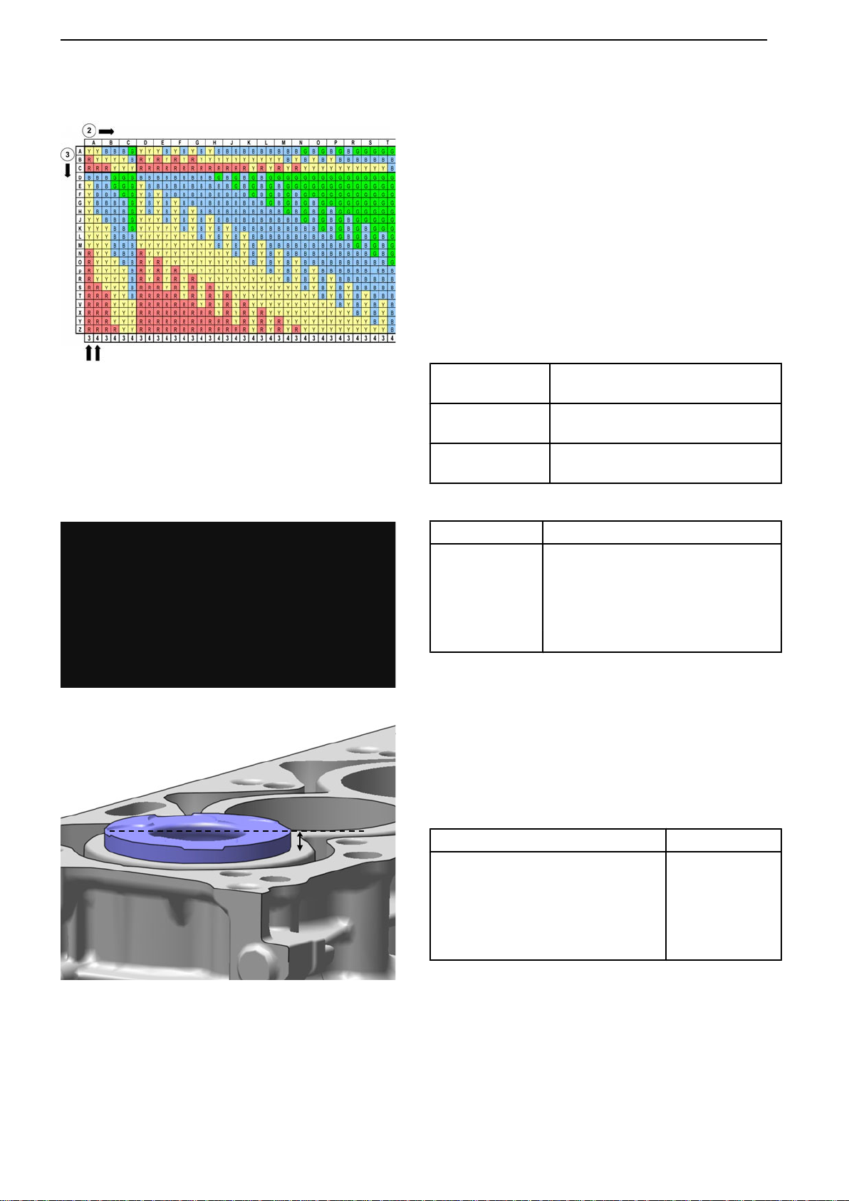
Main bearing classes
A template for identification is available in the workshop manual to make sure that correct bearings are
used within the engine overhaul procedure.
Bore
C-marked 81.00–81.01 mm
(3.18897-3.18936")
D-marked 81.01–81.02 mm
(3.18936-3.18975")
E-marked 81.02–81.03 mm
(3.18975-3.19015")
P0015855
Cylinder head gasket
Classification Hole marking
1 5
2 4, 5
3 3, 4, 5
4 2, 3, 4, 5
5 1, 5
NOTICE!
type and will therefore not affect the classification.
Classification
The following classification measurements for the cylinder head gasket are to be used if the cylinder block
has been replaced.
To measure. see Cylinder Head, Change page 45.
Dist., block surface- piston (TDC) Classification
0.26-0.47 mm (0.0102-0.0185") 1
0.47-0.52 mm (0.0185-0.0205") 2
0.52-0.57 mm (0.0205-0.0224") 3
0.57-0.62 mm (0.0224-0.0244") 4
0.62-0.74 mm (0.0244-0.0291") 5
Hole A and B are only used to identify engine
P0015856
10 47702022 12-2011
Page 13
P0010770
03-2 Specifications, Engine
Pistons
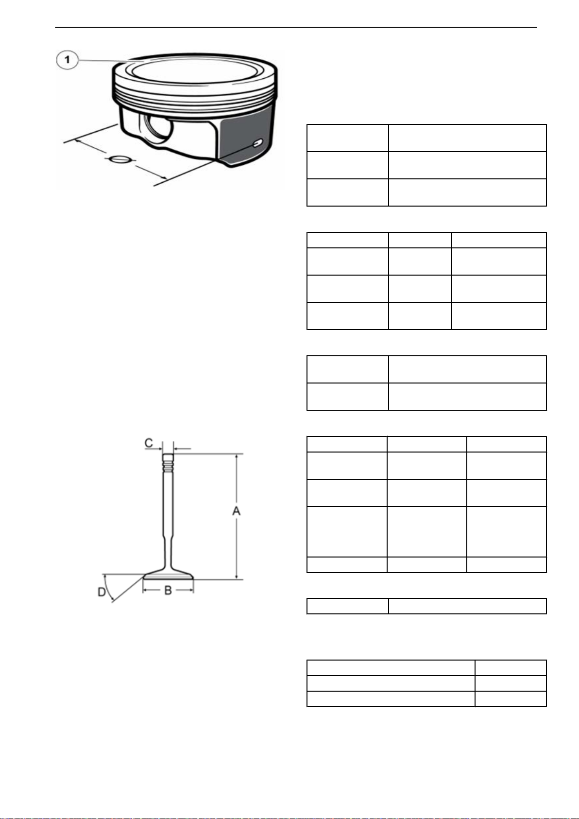
Piston class is stamped on top of the piston.
As standard the diameter is measured 12 mm (0.47")
above the piston lower end.
C-marked (1) 80.95–80.96 mm
(3.18700-3.18739")
D-marked (1) 80.96–80.97 mm
(3.18739-3.18779")
E-marked (1) 80.97–80.98 mm
(3.18779-3.18818")
Piston rings
Thickness Clearance
Top ring 2.0 mm
(0.0787")
First ring 1.75 mm
(0.0689")
Oil ring 2.0 mm
(0.0787")
-0.01–0.03 mm
(-0.0004–0.0012")
-0.01–0.03 mm
(-0.0004–0.0012")
-0.01–0.03 mm
(-0.0004–0.0012")
P0010771
Piston pin
Diameter 24.985-25.0 mm
(0.9837-0.9842")
Length 66.0-66.3 mm
(2.5984-2.6102")
Valves
Inlet Exhaust
Length (A) 98.1 ±0.07 mm
(3.862 ±0.0028")
Plate diameter
(B)
Shaft diameter
(C)
Valve angle (D) 45.0 ±0.5° 45.0 +0.5/-0°
28.0 ±0.1 mm
(1.102 ±0.0039")
5.975 ±0.015
mm
(0.235 ±0.0006")
97.7 ±0.15 mm
(3.846 ±0.0059")
26.2 ±0.1 mm
(1.031 ±0.0039")
5.975 +0/-0.015
mm
(0.235
+0/-0.0006")
Crankshaft
Axial clearance* 0.11-0.30 mm (0.0043-0.0118")
* To be measured with the cylinder block assembled.
Con rods
Diameter, big end 53 mm (2.09")
Diameter, small end 30 mm (1.18")
Length between centre of the ends 147 mm (5.79")
47702022 12-2011 11
Page 14
03-2 Specifications, Engine
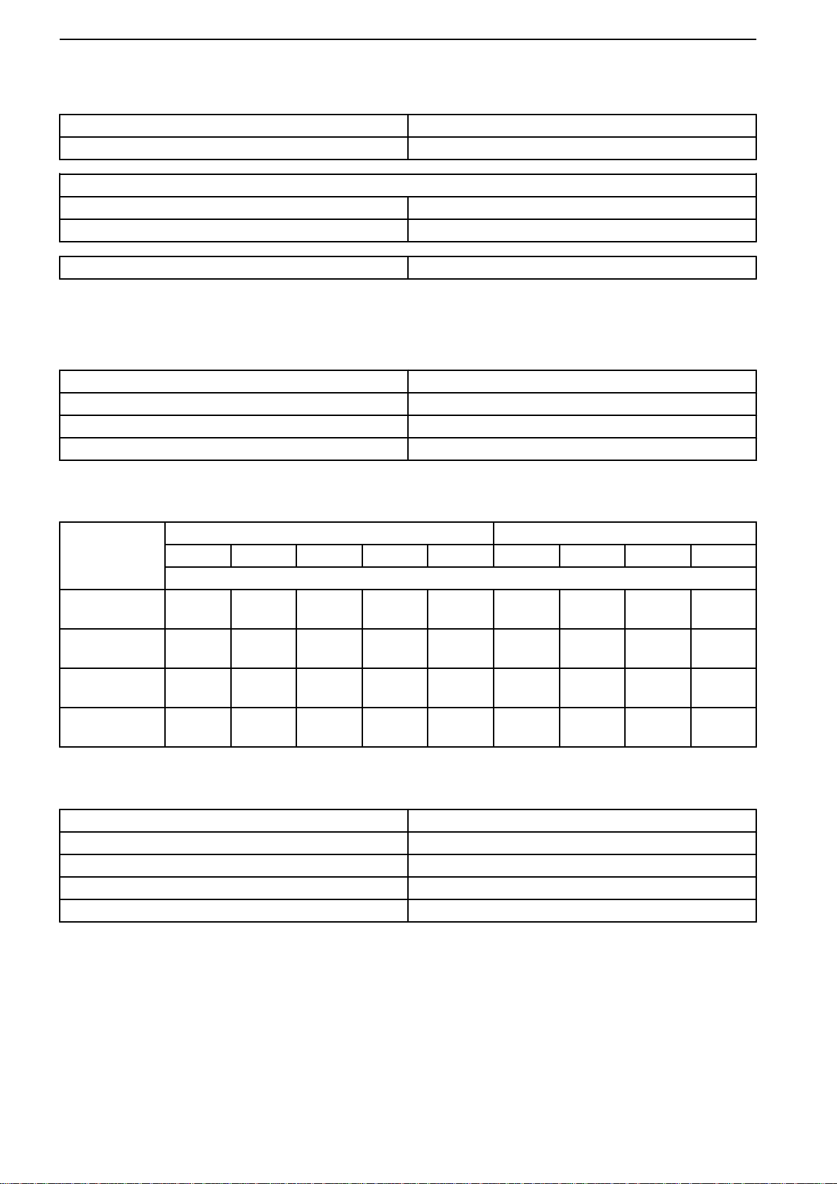
Group 22: Lubrication System
Max. oil level with oil filter 6.3 l (1.66 US gallon)
Max. oil level without oil filter 5.8 l (1.53 US gallon)
Oil pressure at
850 rpm 0.1 MPa (14.5 psi)
4000 rpm 0.35 MPa (50.8 psi)
Max. oil pressure* 0.48 MPa (69.6 psi)
* Safety valve opens.
Group 23: Fuel System
EDC, type Bosch EDC17
Fuel feed pump, type Electrical
High pressure pump, type Bosch CP 4.2
Injectors, type Bosch CRI 3.2
Group 25: Inlet and Exhaust System
Inboard Aquamatic
D3-110 I D3-150 I D3-170 I D3-200 I D3-220 I D3-140 D3-170 D3-200 D3-220
Charge air pressure, kPa (psi)
1200 rpm 128
(18.56)
2000 rpm 199
(28.86)
2800 rpm 198
(28.72)
4000 rpm – – 239
127
(18.42)
229
(33.21)
235
(34.08)
126
(18.27)
230
(33.36)
249
(36.11)
(34.66)
126
(18.27)
229
(33.21)
243
(35.24)
250
(36.26)
127
(18.42)
230
(33.36)
270
(39.16)
274
(39.74)
127
(18.42)
198
(28.72)
206
(39.16)
203
(29.44)
Group 26: Cooling System
Thermostat, opens at 80 °C (176 °)
Thermostat, fully open at 94 °C (201.2 °)
Coolant volume, incl. heat exchanger 8,7 l (2.3 US gallon)
Heat exchanger Seawater cooled
Seawater pump Rubber impeller
126
(18.27)
230
(33.36)
249
(36.11)
239
(34.66)
126
(18.27)
229
(33.21)
243
(35.24)
250
(36.26)
127
(18.42)
230
(33.36)
270
(39.16)
274
(39.74)
12 47702022 12-2011
Page 15
!
05-1 Safety Instructions
05-1 Safety Instructions
Safety Information
This Service Manual contains repair instructions,
descriptions
designs from Volvo Penta. Ensure that you are using
the correct service manual.
Read the safety information below and the service manual section About this Workshop manual and Repair
instructions carefully before repair and service work is begun.
This symbol is used in the service manual and on the product, to call attention to the
fact that this is safety information. Always read such information very carefully.
Safety texts in the manual have the following order of priority:
and technical data for products or product
DANGER!
Indicates a hazardous situation which, if not avoided, will result in death or serious
injury.
WARNING!
Indicates a hazardous situation which, if not avoided, could result in death or serious
personal injury.
CAUTION!
Indicates
personal injury.
IMPORTANT!
Is used to draw your attention to something that may cause minor damage or a minor
malfunction to the product or property.
NOTICE! Is used to draw your attention to important information that will facilitate the
work or operation in progress.
a hazardous situation which, if not avoided, could result in minor or moderate
This symbol is used on our products in certain cases and refers to important information
the instruction book. Make sure that warning and information symbols on the engine
in
are clearly visible and legible. Replace symbols which have been damaged or painted
over.
A compilation of safety precautions that must be taken and risks which must be paid attention to is
presented in the following pages.
47702022 12-2011 13
Page 16

!
!
!
!
!
!
!
!
!
!
!
!
05-1 Safety Instructions
Immobilize the engine by turning off the power
supply to the engine at the main switch
(switches) and lock it (them) in the off position
before starting work. Post a warning notice at
the main circuit breaker.
As a rule, all service operations must be carried
out with the engine stopped. However, some
work, such as adjustments, will require the
engine to be running. Approaching an engine
which is running is a safety risk. Bear in mind
that loose clothing or long hair can fasten in
rotating parts and cause serious personal
injury.
Be aware of hot surfaces (exhaust pipes, turbos,
charge air pipes, starting heaters etc.) and
hot fluids in pipes and hoses on an engine that
is running or has just stopped.
If work is done adjacent to a running engine, a
careless movement or a dropped tool may in the
worst case lead to personal injury.
Avoid opening the coolant filling cap when the
engine is hot. Steam or hot coolant can spray
out and system pressure will be lost. Open the
filler
cap slowly, and release the pressure in the
cooling system if the filler cap or valve has to be
opened, or if a plug or coolant hose has to be
removed when the engine is hot.
Hot oil can cause burns. Avoid skin contact with
hot
oil. Ensure that the lubrication system is not
under pressure before any work is begun.
Never start or operate the engine with the oil
filler cap removed, because of the risk of oil
ejection.
Never start the engine without installing the air
filter.
The rotating compressor turbine in the turbocharger can cause severe injury. Foreign
objects entering the intake ducts can also cause
mechanical damage. Install all protective covers before the engine is started.
Ensure that the warning symbols or information
decals
Replace decals which have been damaged or
painted over.
Avoid getting oil on your skin! Protracted or
repeated exposure to oil can cause skin to
become dry. Irritation, dryness, eczema and
other skin problems may then result. From a
health standpoint, used oil is more dangerous
than new. Use protective gloves and avoid oilsoaked
cially before eating. Use suitable barrier creams
to counteract drying out of the skin and to aid
dirt removal.
Stop the engine and turn off the electrical supply
at
on the electrical system.
on the product are always clearly visible.
clothes and rags. Wash regularly, espe-
the main switch(es) before carrying out work
Only start the engine in a well-ventilated space.
When running in a confined space, exhaust
fumes and crankcase gases must be led away
from the engine bay or workshop area.
The majority of chemicals e.g. engine and transmission oils, glycol, gasoline, and diesel oil,
together
as degreasing agents, paints and solvents, are
injurious to health. Carefully read the instructions on the product packaging! Always follow a
product's safety directions, e.g. use of protective mask, glasses, gloves etc. Ensure that
other personnel are not exposed to substances
that are injurious to health. Ensure good ventilation. Handle used and leftover chemicals in
the prescribed manner.
Clutch adjustments must be carried out with the
engine stopped.
with chemicals for workshop use such
14 47702022 12-2011
Page 17

!
!
!
!
!
!
!
!
!
!
05-1 Safety Instructions
Always use protective glasses or goggles when
carrying out work where a risk of splinters,
grinding sparks, splashes from acid or other
chemicals is present. Your eyes are extremely
sensitive; injury may cause blindness!
Never use start gas or similar products as a
starting
inlet manifold. Danger of personal injury.
All fuels, as well as many chemicals, are flammable. Do not allow open flames or sparks in
their vicinity. Gasoline, some thinners, and
hydrogen gas from batteries are extremely
flammable
the correct proportions. No Smoking! Ensure
that the work area is well ventilated and take the
necessary safety precautions before welding or
grinding work is begun. Always ensure that
there are fire extinguishers close at hand in the
work area.
aid. They may cause an explosion in the
and explosive when mixed with air in
Never start the engine with the valve cover
removed. There is a risk of personal injury.
Stop the engine before working on the cooling
system.
Marine engines: Close the sea cock / cooling
water
inlet valve before work on the cooling sys-
tem is begun.
Make sure that oil, fuel-soaked rags, and used
fuel and oil filters are stored in a safe manner.
Rags soaked in oil can spontaneously ignite
under certain circumstances. Used fuel and oil
filters are environmentally hazardous waste
and must be handed to an approved waste
management facility for destruction, as must
any used lubrication oil, contaminated fuel,
paint residue, solvents, degreasers and wash
residue.
Batteries must never be exposed to open
flames or electric sparks. Never smoke in the
vicinity
gas when charged, which is explosive when
mixed with air. This gas is easily ignited and
highly explosive. A spark, which can be caused
by incorrect battery connection, is sufficient to
cause a battery to explode and cause damage.
Do not touch the connections during start
attempts. Sparking hazard! Do not lean over
batteries.
Never transpose the positive (+) and negative
(-)
a transposition can result in serious damage to
electrical equipment. Refer to the wiring diagram.
Always use protective goggles when charging
and handling the batteries. Battery electrolyte
contains sulfuric acid which is highly corrosive.
Should the battery electrolyte come into contact
with unprotected skin, wash it off immediately
using soap and copious amounts of water. If you
get battery acid in your eyes, flush at once with
copious amounts of water and seek medical
assistance immediately.
of the batteries; they generate hydrogen
battery posts when installing batteries. Such
Never work alone when removing heavy components, even when using lifting devices such
as locking tackle lifts. When using a lifting
device, two people are usually required to do
the work - one to take care of the lifting device
and the other to ensure that components are
lifted clear and not damaged during the lifting
operations.
The existing lugs on the engine should be used
for lifting. Always check that the lifting equipment
used is in good condition and has the load
capacity to lift the engine (engine weight including gearbox or extra equipment). For safe handling and to avoid damaging components fitted
to the top of the engine, the engine must be
lifted with a correctly adjusted lifting boom. All
chains or wires must run parallel to each other
and as perpendicular to the engine as possible.
If other equipment attached to the engine has
altered its center of gravity, special lifting devices may be needed to obtain the correct balance for safe handling. Never perform any work
on an engine that is only suspended from the
lifting equipment.
47702022 12-2011 15
Page 18

!
!
!
!
!
05-1 Safety Instructions
The components in the electrical and fuel systems
on Volvo Penta products are designed and
manufactured to minimize the risk of fire and
explosion. The engine must not be run in areas
where there are explosive materials.
Only use fuels and lubricating oils recommended
Manual for the product in question. Use of fuels
that are of a lower grade may damage the
engine, the injection pump and the injectors. On
a diesel engine, low grade fuel can cause the
control rod to bind and the engine to over-rev,
with the risk of engine damage and personal
injury as a result. Low fuel and oil grades may
result in high service, maintenance and repair
costs.
Fuel delivery pipes must not be bent or straightened under any circumstances. Cracks may
occur. Damaged pipes must be replaced.
by Volvo Penta. Refer to the Operator's
Exercise extreme caution when leak-detecting
on the fuel system and testing the fuel injector
nozzles.
nozzle has very high pressure and great penetration power. Fuel can force its way deep into
body tissue and cause severe injury. There is a
risk of blood poisoning (septicemia).
Never use a high-pressure washer for cleaning
the engine.
Pay
pressure washer on components other than the
actual engine: Never direct the water jet at
seals, rubber hoses or electrical components.
Use eye protection. The jet from a fuel
attention to the following when using a high-
16 47702022 12-2011
Page 19
P0007807
P0002943
P0002930
P0001875
-100
-80
-60
-40
-20
0
P0002942
P0002937
P0007808
p0014391
08-2 Special Service Tools
08-2 Special Service Tools
Special tools
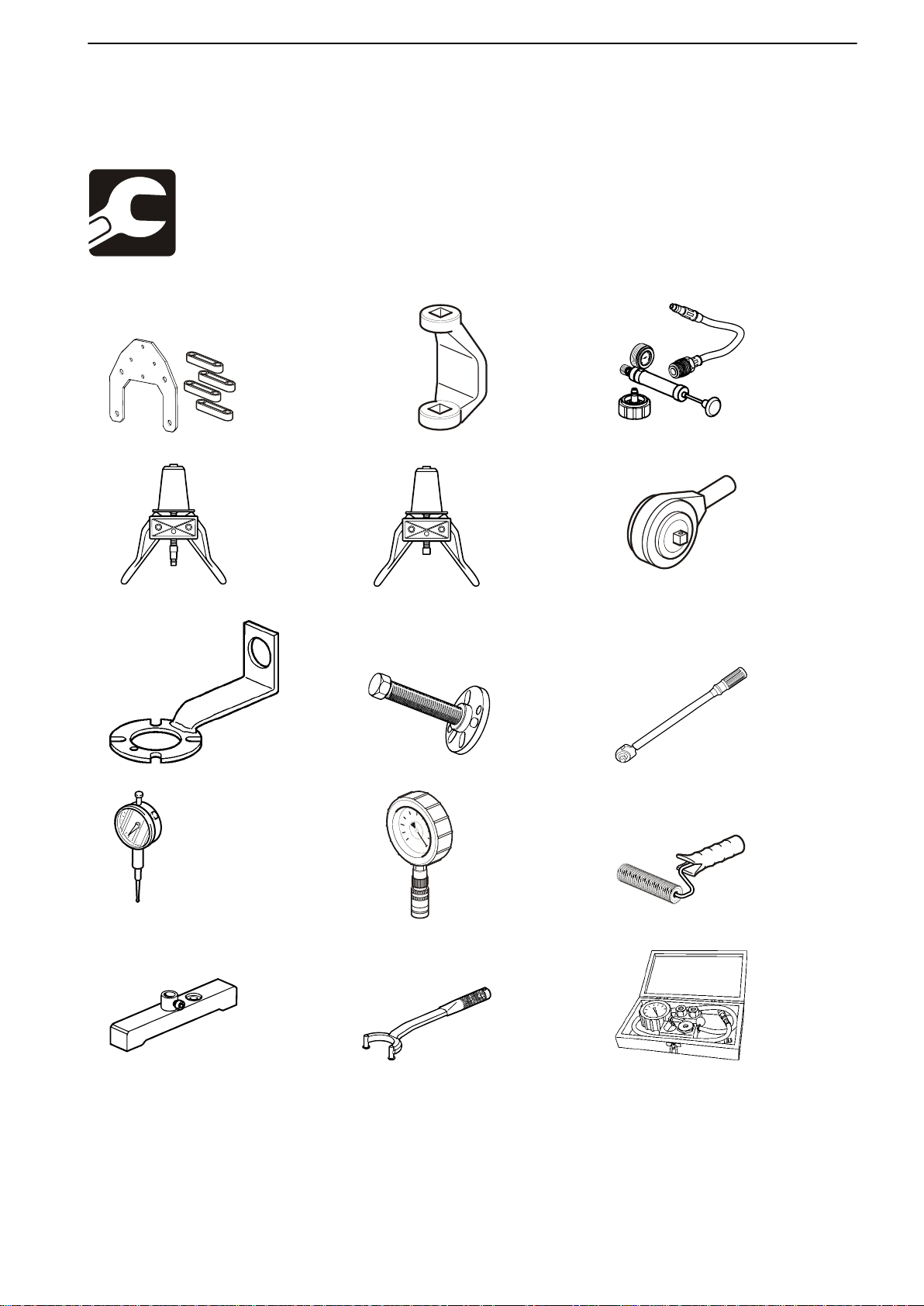
The following special tools are used when working on
the engine. The tools can be ordered from AB Volvo
Penta by specifying the number indicated.
885224 Fixture 885490 Sleeve 885531 Pressure testing kit
885536 Plug 885539 Plug 885633 Torque multiplier
885819 Counterhold 885820 Puller 1158688 Torque wrench
9989876 Dial indicator 9990150 Manometer 9992767 Roller
9995192 Gauge rod 9995199 Drift 9995270 Pressure gauge
47702022 12-2011 17
Page 20
P0007809
P0002947
P0004331
P0004333
P0014392
p0014393
P0014451
p0014394
P0004348
P0004580
P0011954
08-2 Special Service Tools
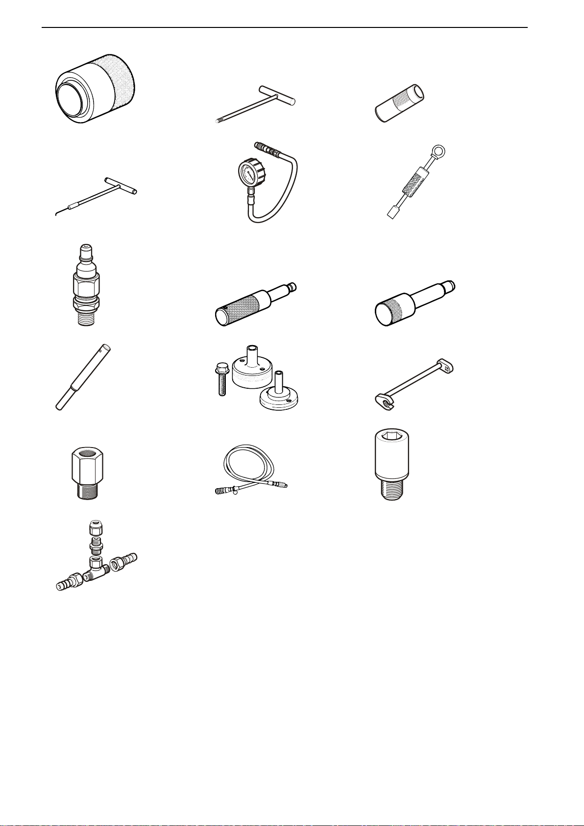
9995455 Mounting tool 9995746 Puller 9995747 Protective sleeve
9995919 Extractor 9996398 Manometer 9996400 Slide hammer
9996666 Nipple 9997005 Rotation tool 9997007 Lock pin
9997009 Brush 9997174 Mounting tool 9997217 Wrench
9998007 Adapter 9998493 Hose 21427201 Guide sleeve
21433378 Nipple
18 47702022 12-2011
Page 21

20-0 Engine Information, General
Lifting the Engine, Actions
Before lifting the engine
Boat removed from the water
Turn the main switch off. Undo the battery con-
1
nections to the engine.
2 Disconnect the harness terminals for the secon-
dary fuel filter and the trim pump. Undo the throttle
cable from the engine control unit. Remove the
box containing the engine control unit from the
bulkhead. Remove the ground cable from the
shield.
3 Remove the seawater connection.
4 Remove the exhaust pipe (baffle).
5 Aquamatic only
Drain the power steering system hydraulic oil via
the drain valve under the system oil cooler. Undo
the hydraulic connections on the steering cylinder. Remove the power steering oil reservoir.
20-0 Engine Information, General
6 Close the fuel taps. Remove the fuel connections.
7 Disconnect the drive at the shield (if an AQ is fit-
ted) or disconnect the propeller shaft at the
reverse gear (inboard).
8 Undo the engine mounts from the beds and the
flywheel housing. Lift out the engine.
Actions after lifting the engine
1 Clean the engine.
IMPORTANT!
Do not use a power washer. There is a risk that
the engine components are subjected to waterlogging.
2 Pump out the engine oil (as necessary).
47702022 12-2011 19
Page 22

20-0 Engine Information, General
Actions before working in boat
Switch off the current at the main switch and
1
check that the engine is without power.
2 Clean the outside of the engine.
NOTICE! Make sure that wash residue is collected for disposal and does not inadvertently end
up in the environment.
3 The work includes the following actions on the
cooling system: Close the sea cocks and drain
the coolant from the seawater and fresh water
systems.
IMPORTANT!
Make sure that all seawater inlets are securely
closed so that water cannot enter the boat during
removal of cooling system sub-components.
20 47702022 12-2011
Page 23
P0010766
20-0 Engine Information, General
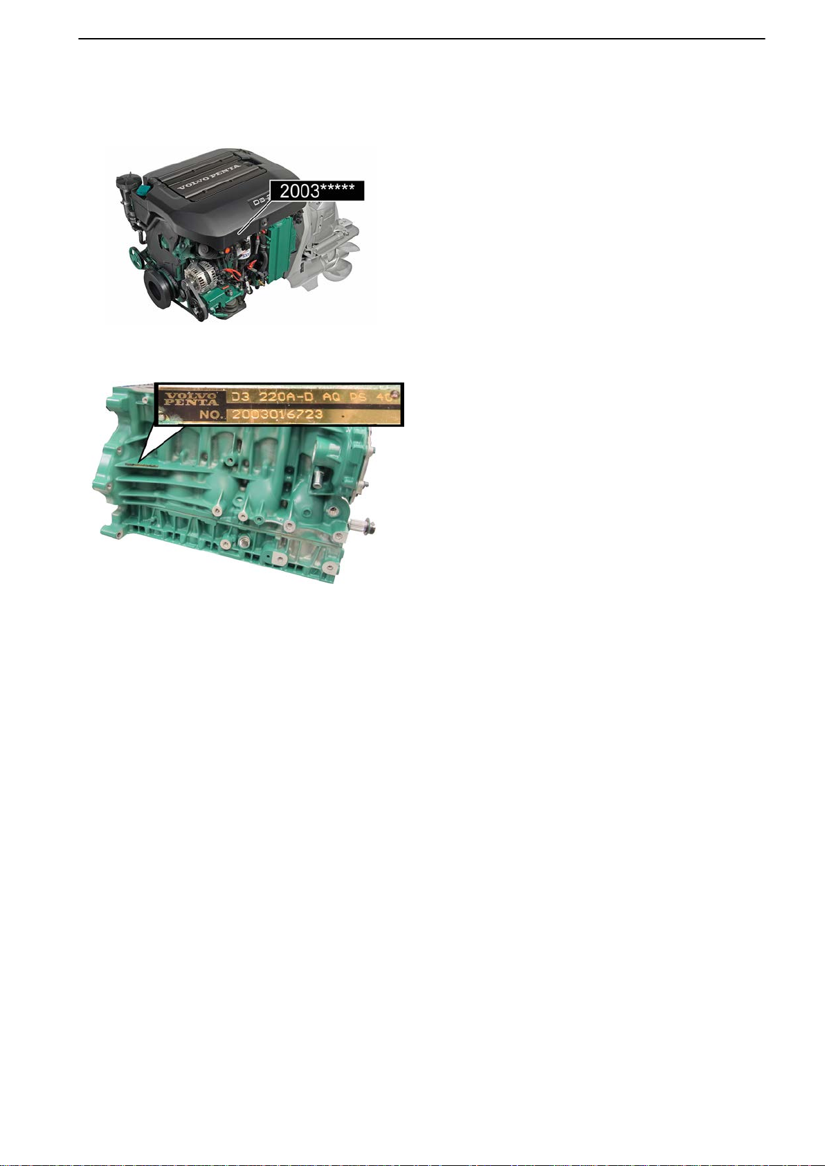
Model Identification
There are two ways in which to identify an engine.
A decal on the engine cover (cold side).
-
- An identification plate riveted to the back of the
engine block (hot side).
P0010767
47702022 12-2011 21
Page 24
20-0 Engine Information, General
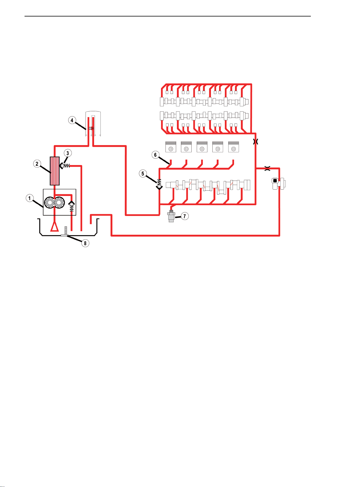
Design and Function
Group 22: Lubrication System
P0012383
The oil pump (1)
a flow capacity of 69 l/min (18.2 US gallon/min) at
4000 rpm and an oil temperature of 100 °C (212 °F),
at a pressure of 3 bar (43.5 psi).
The oil pump cannot be repaired but must be
exchanged if it becomes defective. The pump inner
rotor is spline driven directly from the crankshaft. The
pump has an internal safety valve that opens at 8 bar
(116.0 psi).
Oil flows from the pump to the water-cooled oil cooler
(2) located on the right side of the oil sump.
The relief valve (3) is located after the oil cooler and
maintains oil pressure at a maximum of 5.5 bar
(79.8 psi).
Cooled oil is then fed to the oil filter (4) via an integral
pipe in the lower crankcase/engine bed.
is of the rotor (duo centric) type with
Oil from the filter is distributed to the connecting rod
bearings via ducts in the main gallery.
Oil is also distributed to the pistons via piston cooling
nozzles (6) below the side gallery.
Pressure is regulated by a valve (5) that opens at
1.35 bar (19.6 psi). Oil is led up to the cylinder head,
the hydraulic valve lifter roller bearings and the camshaft via a vertical duct at the front of the block.
An oil pressure sensor (7) is located in the cylinder
block - engine bed for monitoring.
A combined oil level/temperature sensor (8) is installed in the bottom of the oil sump.
22 47702022 12-2011
Page 25
20-0 Engine Information, General
Group 23: Fuel System
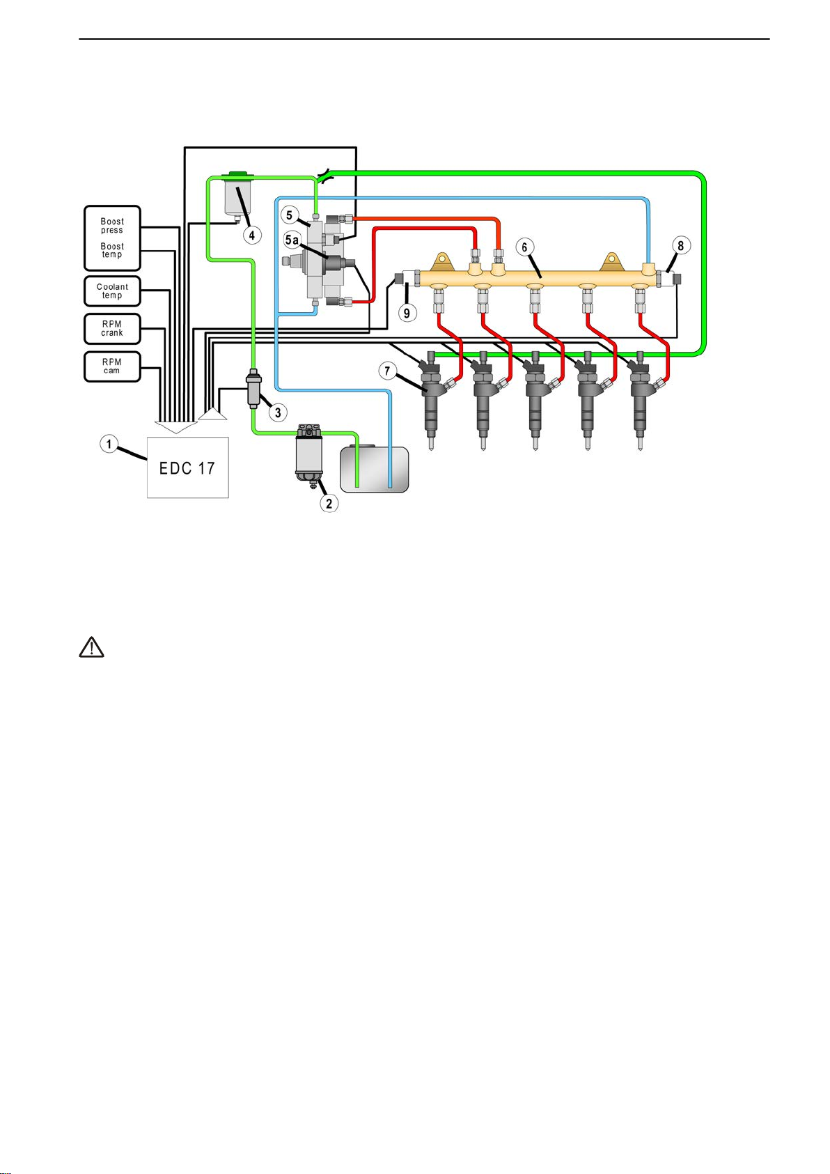
P0012207
CAUTION!
Never disconnect a fuel line or component after the
fuel pump to bleed. The fuel is under very high pressure and can penetrate the skin.
not try to measure any pressure without checking
Do
the workshop manual!
The electrical feed pump (3) is controlled by the EDC
17 (1) . Fuel is sucked from the fuel tank through the
pre-filter to the feed pump, the feed pump increases
the fuel feed pressure to approx 4 bars (p-norm 3,8 –
4,2 bar).
The fuel is then pumped through the fine filter (4)
before it enter the High Pressure pump (5).
A magnetic proportional valve is mounted in the Hp
pump to regulate the expected output pressure to the
fuel rail (6).
The new Piezo injectors (7)
rail. One big difference compared to previous systems
is that the injectors have fuel pressure on the leak-off
side.
*The PCV valve replaces the old security relief valve
and it's main function is to stabilise the hp pressure in
the fuel rail.
It controls and manages the pressure together with
the M-prop valve especially at engine deceleration.
The PCV valve is fully open when it is not energised
(No Current).
This type of system is called Coupled Pressure Control (CPC).
are supplied from the fuel
The fuel rail is equipped with one fuel pressure sensor
(9) and one Pressure Control Valve (8)*.
47702022 12-2011 23
Page 26
P0011256
20-0 Engine Information, General
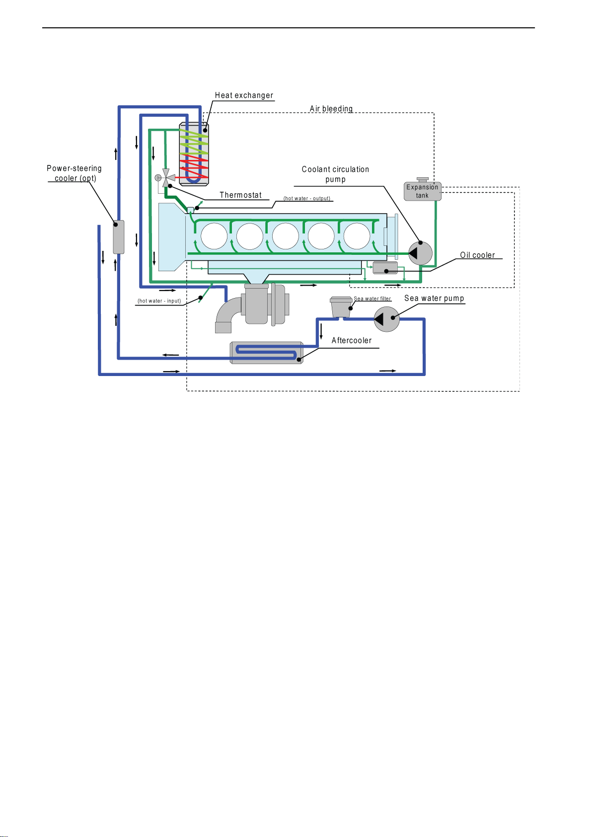
Group 26: Cooling System
The engine is fresh water cooled and Volvo type 90
coolant must be used. The turbocharger is not water
cooled but has instead a protective cover to prevent
turbocharger heat from presenting a hazard.
The oil is cooled by an oil cooler located at the lower,
front right on the oil pan.
Oil temperature is maintained at the correct level by
means of an oil thermostat. Refer to Group 22: Lubri-
cation System page 22.
The engine has a power steering (accessory) cooler
at the rear.
Seawater circuit
Seawater is drawn in by the seawater pump on the
right side of the engine and lead through a seawater
filter before reaching the charge air cooler. After the
charge air cooler it passes the power steering (accessory) cooler at the rear of the engine. The water is then
led to the heat exchanger on the left side of the
engine.
Finally, seawater passes through the exhaust elbow
where it cools exhaust gases and is discharged.
Freshwater circuit
Coolant enters the engine at the front and cools the
engine block via transverse channels. The coolant is
discharged at the left rear. If coolant is still cold it
passes the thermostat directly back to the circulating
pump and enters the engine block again. The oil
cooler is located parallel with the main return line and
does not have a separate thermostat on the water
side. Refer to oil cooling in Group 22: Lubrication Sys-
tem page 22.
The exhaust manifold has its own connection at the
rear right where coolant is led through the exhaust
manifold and on to the main return line.
If the coolant is too hot the thermostat opens and
coolant is led through the heat exchanger where it is
cooled. It is then drawn into the circulating pump and
returns to the engine block. There is an expansion
tank at the front of the engine where expanded coolant and air are collected.
The engine has three venting points: 1. Heat
exchanger, 2. Cylinder Head (rear) and 3. Exhaust
Manifold.
24 47702022 12-2011
Page 27
21-0 Engine Complete, General
Engine, Overhaul
Tools:
885224 Fixture
885820 Puller
9995746 Puller
Removal
21-0 Engine Complete, General
P0014642
Remove
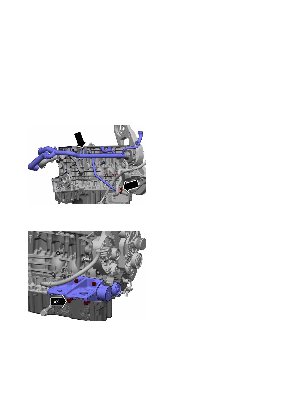
Change page 45.
Remove the rear crankshaft seal according to: Crank-
shaft Seal, Change (rear) page 80.
1 Remove the coolant pipe.
2 Remove the oil cooler according to Oil Cooler,
3 Remove the engine mount on the engine hot side.
the cylinder head according to Cylinder Head,
Replace page 91.
Tightening torque: M10, 60 Nm (44.3 lbf.ft.)
P0014643
4 Remove the alternator according to Alternator,
Change page 141.
5 Remove the wire harness:
- Flywheel sensor
- B+ cable, starter motor-alternator
- Coolant temperature sensor
- Ground
- Oil level sensor
- Oil pressure sensor
- Attachment, oil trap
47702022 12-2011 25
Page 28
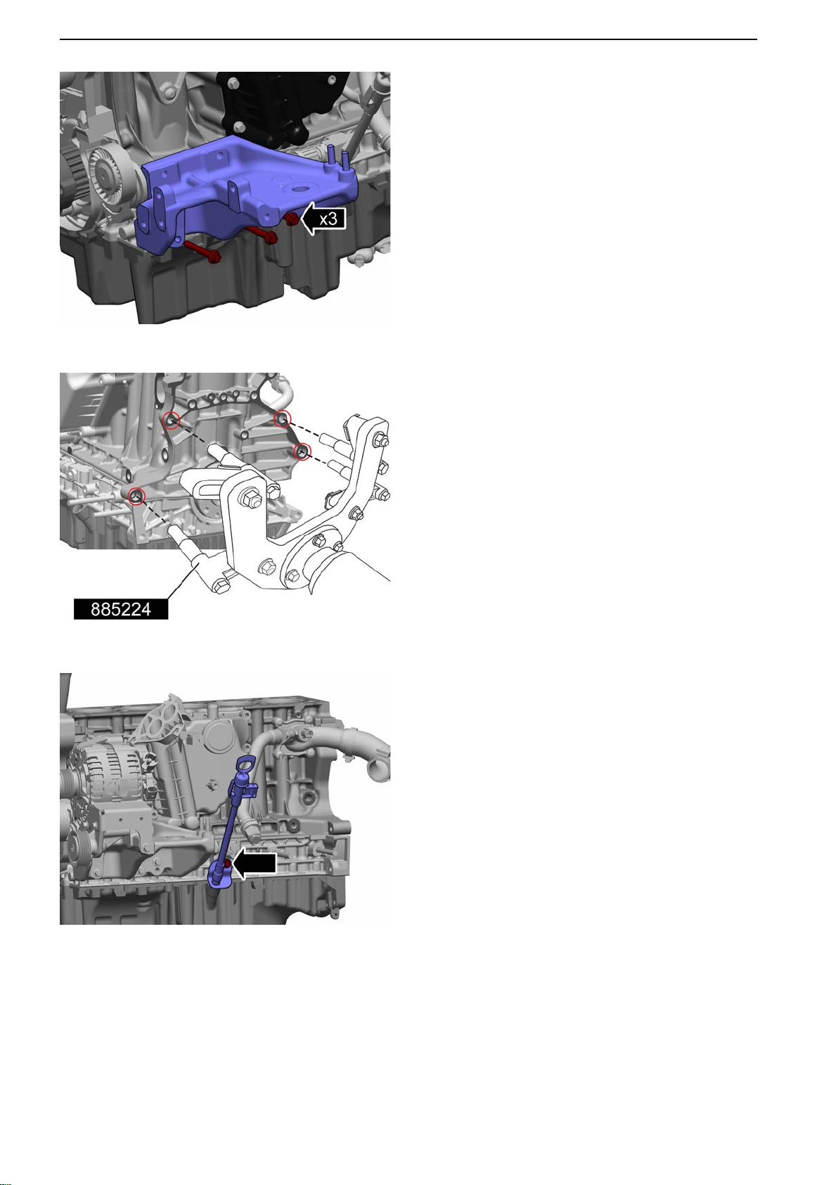
21-0 Engine Complete, General
P0014644
6 Remove the engine mount on the engine cold
side.
Tightening torque: M8, 30 Nm (22.1 lbf.ft.)
7
Fit the attachment. Use 885224 Fixture.
Place the engine in a stand.
P0014645
P0014646
8 Remove the oil dipstick.
9 Remove the oil pressure sensor according to Oil
pressure sensor, replace page 154.
26 47702022 12-2011
Page 29
P0014647
21-0 Engine Complete, General
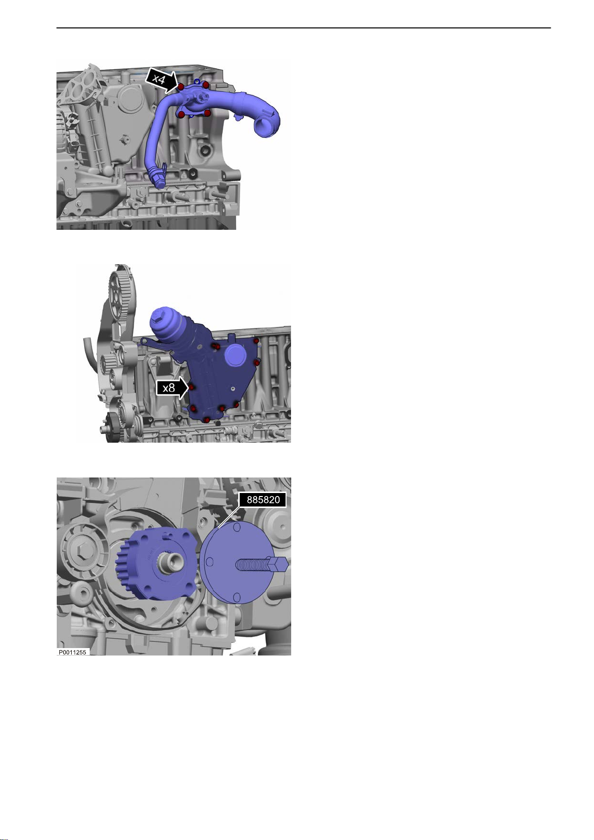
10 Remove the distributing pipe.
Early model
When
installing the early model with O-ring sealant (part # 1161059) must be applied to the flat
surface between the O-ring and the duct.
Late model
When installing the late model with flat gasket,
sealant must not be applied.
Tightening torque: M7, 17 Nm (12.5 lbf.ft.)
11 NOTICE! Be prepared to gather up fluids.
Remove the crank case ventilation oil trap.
Tightening torque: M6, 10 Nm (7.4 lbf.ft.)
P0014648
12 Remove the timing gear. Use 885820 Puller.
13 Remove the oil pump according to Lubrication Oil
Pump, Change page 89.
14 Remove the seawater pump according to Sea-
water Pump, Change page 139.
47702022 12-2011 27
Page 30
21-0 Engine Complete, General
P0014649
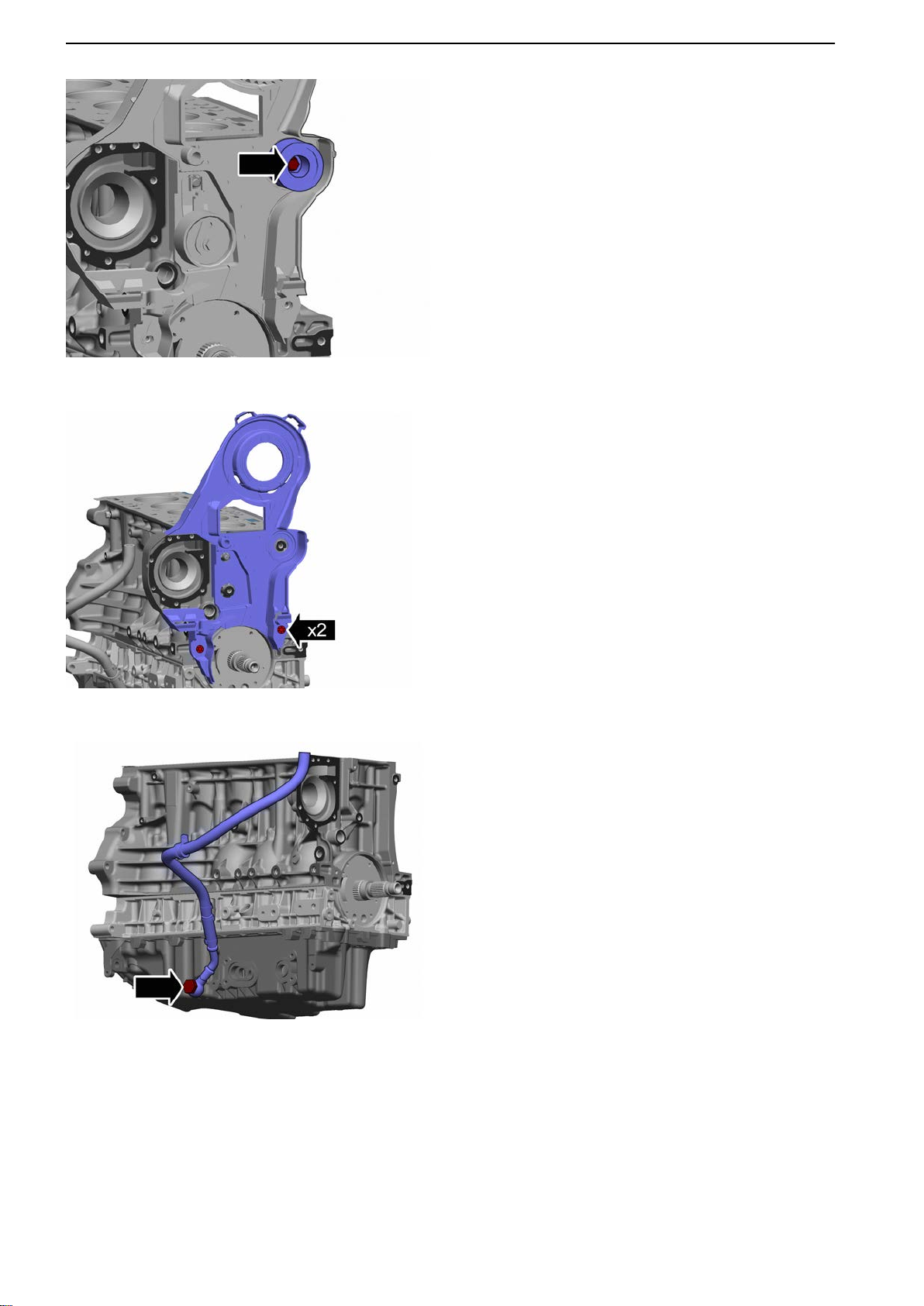
15 Remove the camshaft belt idler wheel.
Tightening torque: M8, 24 Nm (17.7 lbf.ft.)
16
Remove the belt guard.
Tightening torque: M6, 10 Nm (7.4 lbf.ft.)
P0014650
P0014651
17 Remove the crank case ventilation return hose.
Tightening torque: 38 Nm (28.0 lbf.ft.)
28 47702022 12-2011
Page 31
P0014652
21-0 Engine Complete, General
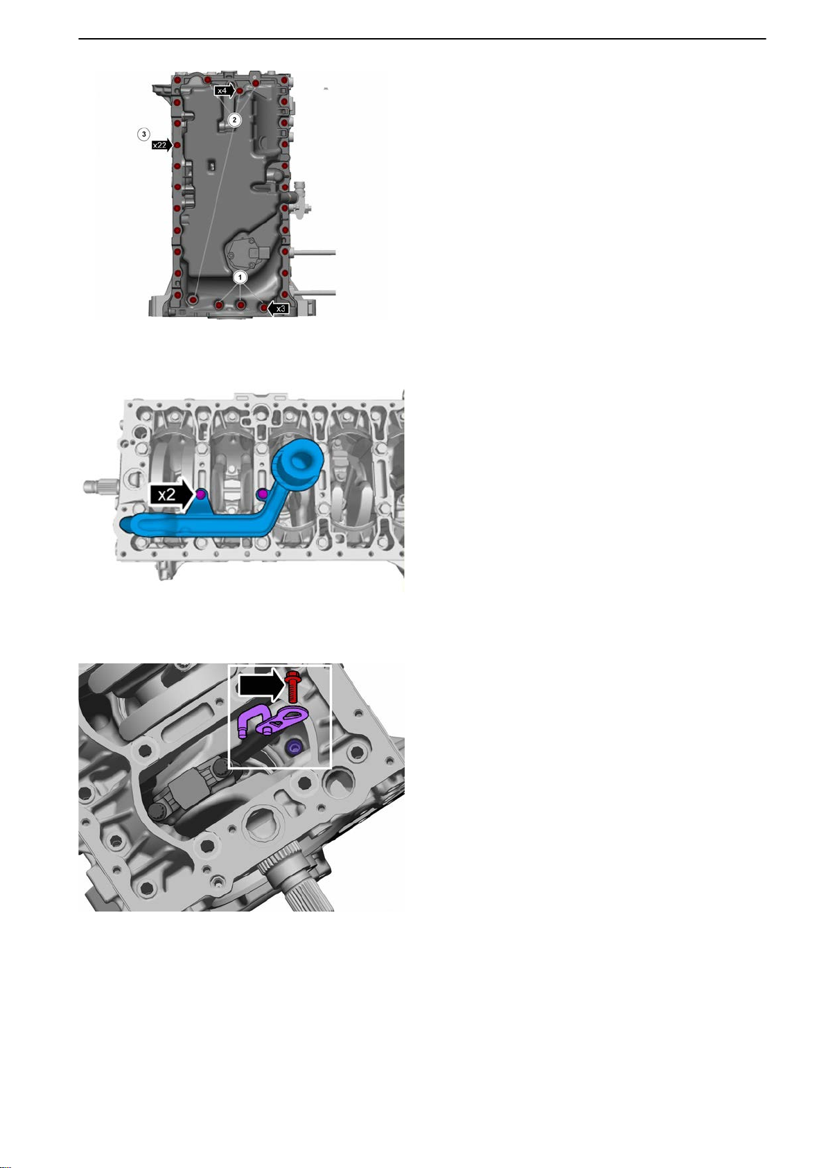
18 Remove the oil sump.
19
Remove the suction strainer.
P0014653
P0014654
20 Rotate cylinder # 1 piston so that the piston cool-
ing nozzle is accessible.
Remove cylinder # 1 piston cooling nozzle.
21 Repeat the above procedure for cylinders 2-5.
47702022 12-2011 29
Page 32
21-0 Engine Complete, General
P0014655
22 NOTICE! Put
the bearing caps with their respec-
tive connecting rods after removal.
IMPORTANT!
Take care with contact surfaces.
IMPORTANT!
Note component locations before removal.
Rotate cylinder # 1 piston so that the bearing cap
is accessible.
Remove the bearing cap from the cylinder # 1
connecting rod.
23 IMPORTANT!
Take care with contact surfaces.
Remove the piston together with the connecting
rod. Use 9995746 Puller.
24 Repeat the above procedure for cylinders 2-5.
P0014656
P0014657
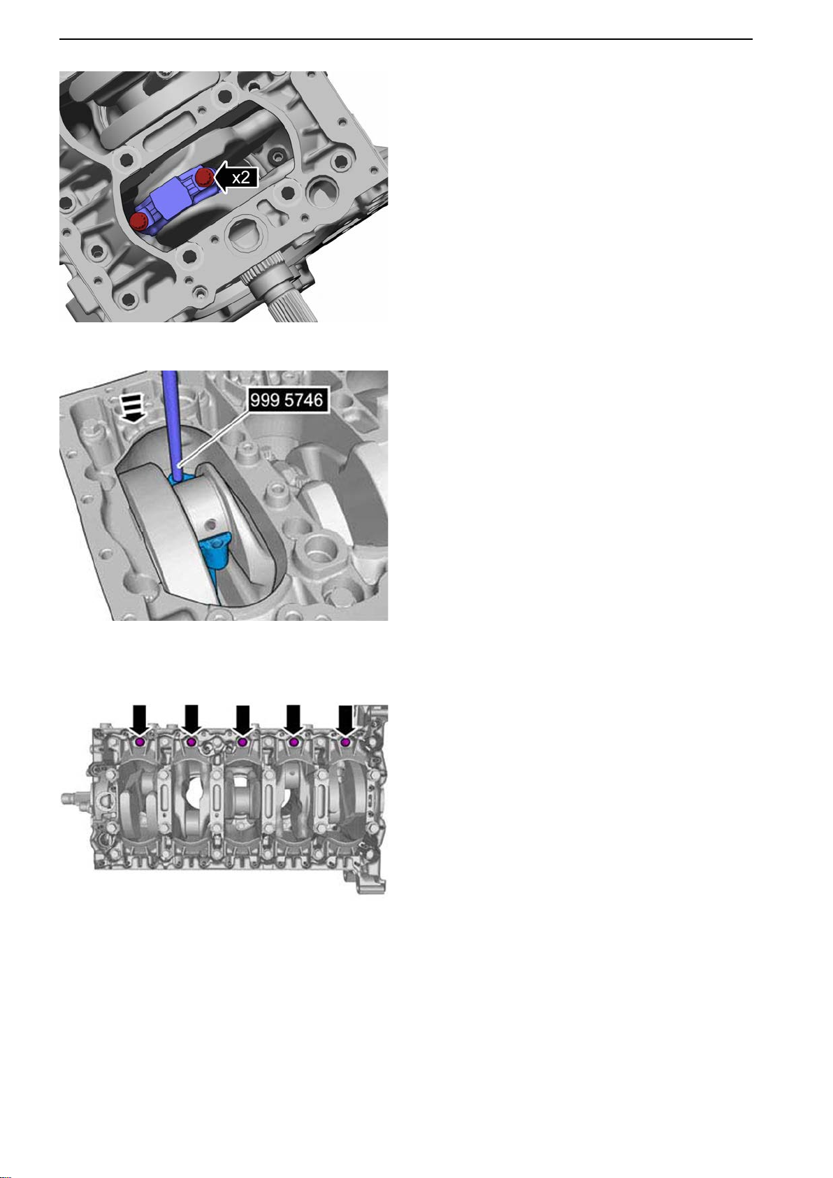
25 Remove the bolts.
30 47702022 12-2011
Page 33
P0014658
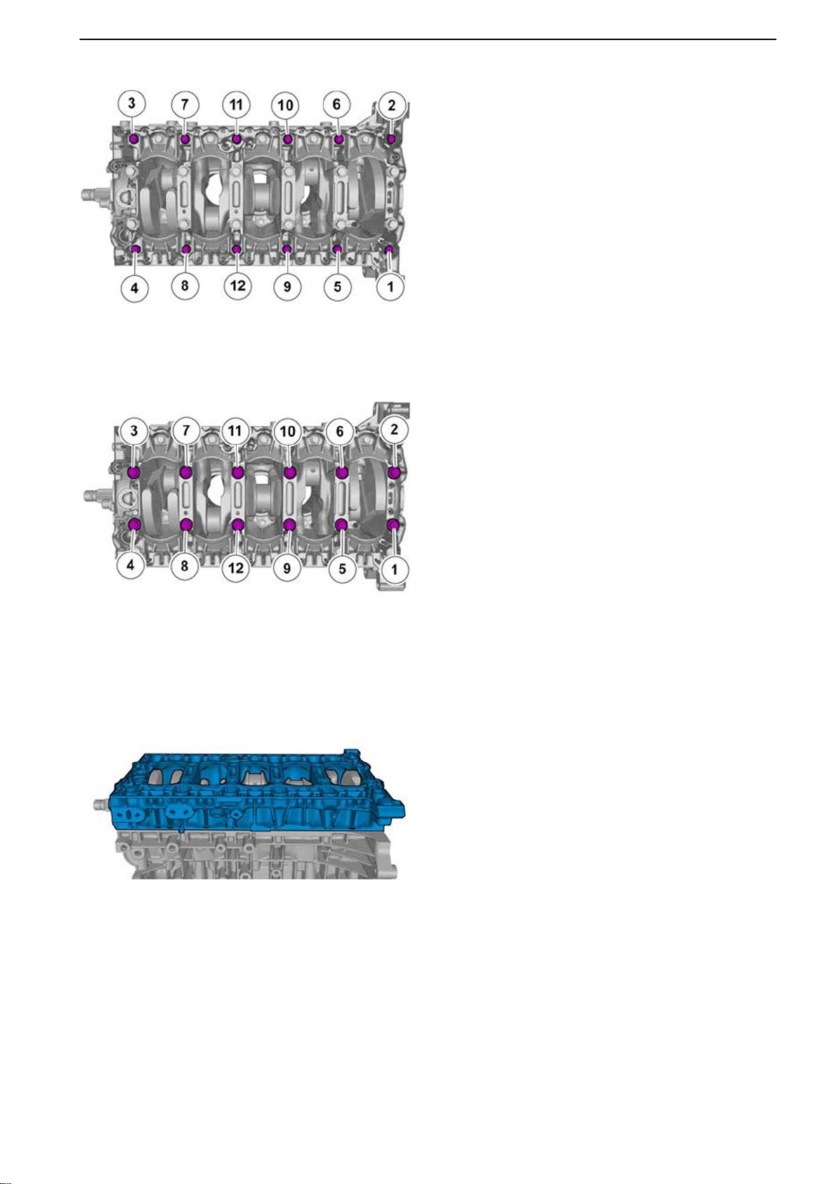
26 Remove the bolts.
27
Remove the bolts.
21-0 Engine Complete, General
P0014659
P0014660
28 Remove the intermediate section.
47702022 12-2011 31
Page 34
21-0 Engine Complete, General
P0014661
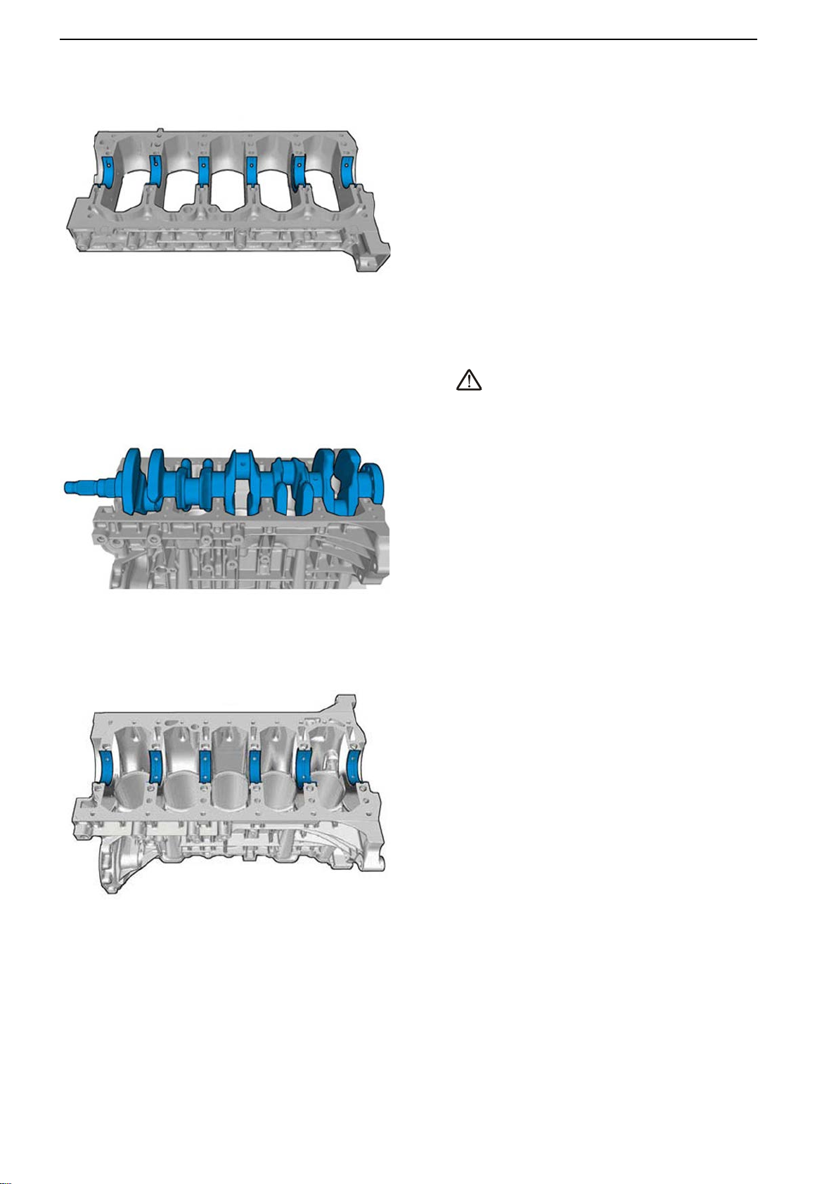
29 Remove the crankshaft bearings from the inter-
mediate section.
P0014662
30
CAUTION!
Heavy
object. Use lifting device when installing or
removing.
Remove the crankshaft.
31 Remove the crankshaft bearings from the cylin-
der block.
P0014663
32 47702022 12-2011
Page 35
P0014664
21-0 Engine Complete, General
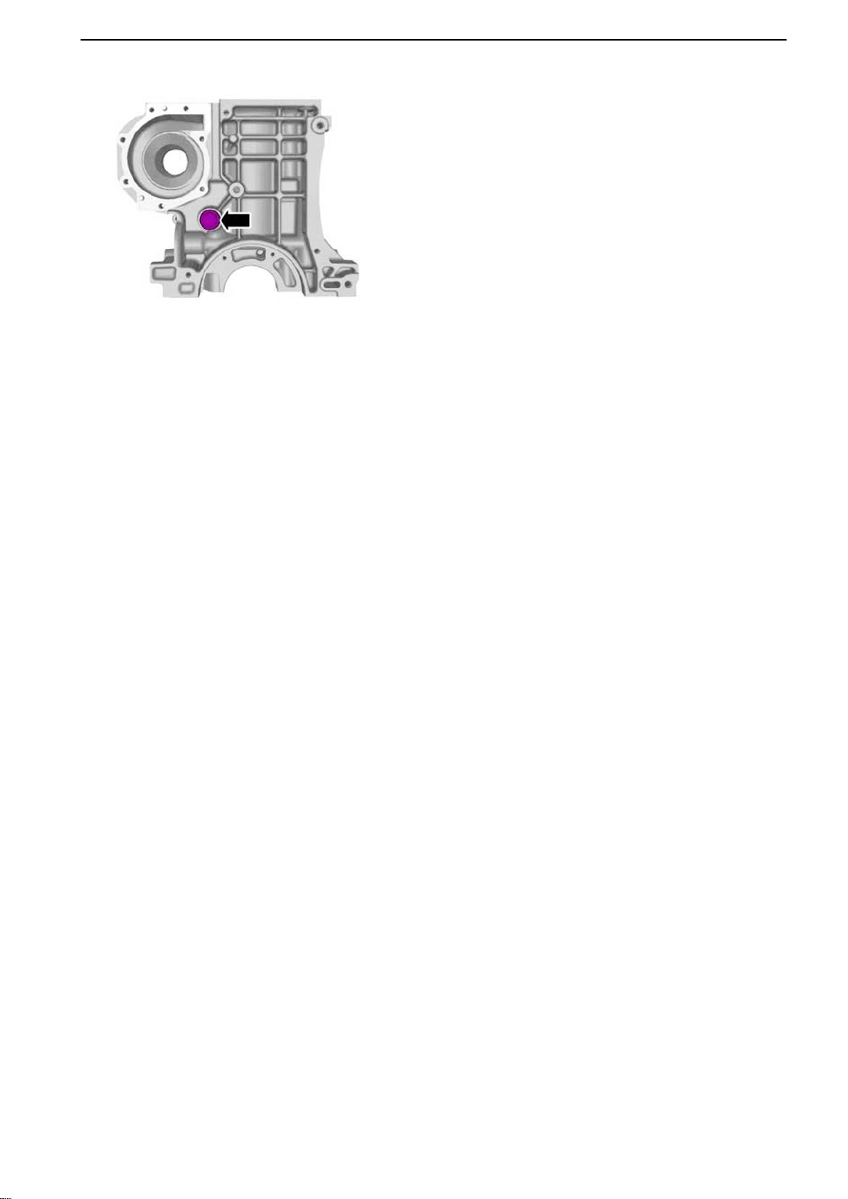
32 Remove the piston cooling valve.
47702022 12-2011 33
Page 36
21-0 Engine Complete, General
P0014664
Installation
NOTICE! Make sure that all ducts are cleaned before
installation is begun.
33
Install the piston cooling valve.
Tightening torque: 50 Nm (36.9 lbf.ft.)
P0014636
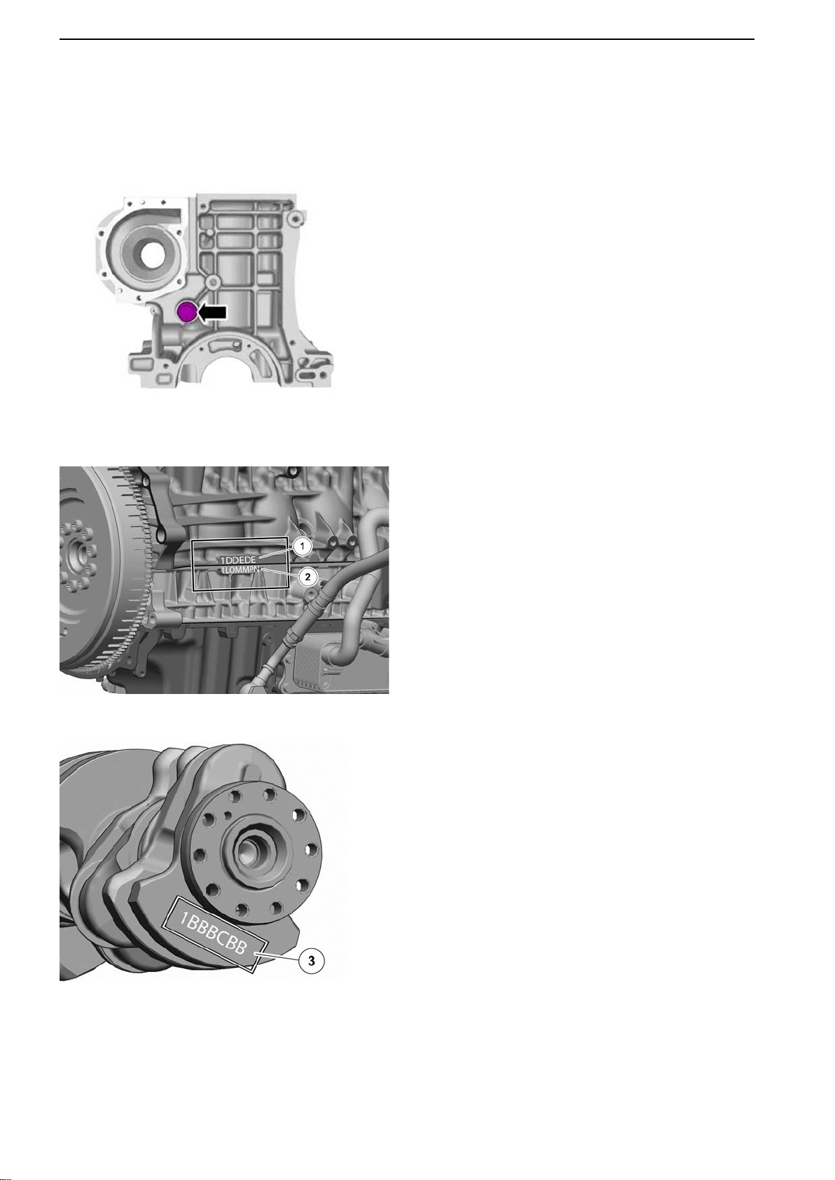
34 NOTICE! Always use new bearings.
There is an engine classification mark at the cylinder block/intermediate section interface.
1 Classification, cylinder bore
2 Classification, cylinder block
35 The crankshaft classification is located on the
crankshaft.
3 Classification, crankshaft
P0014637
34 47702022 12-2011
Page 37
21-0 Engine Complete, General
36 Example 1
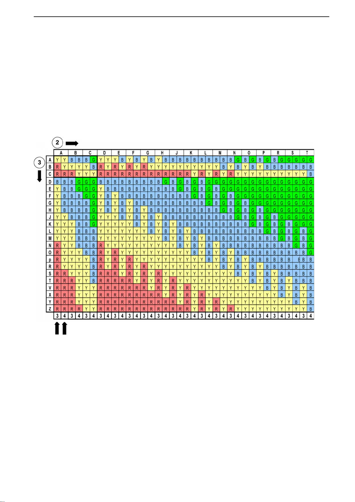
The
marking on the block at bearing position 1 is
L. The marking on the crankshaft at the corresponding bearing position is B. This means the
bearing in the block is marked yellow as is the one
in the intermediate section.
Example 2
The marking on the block at bearing position 2 is
O. The marking on the crankshaft at the corresponding bearing position is B. This means the
bearing in the block is marked yellow and the one
in the intermediate section is marked blue.
2 Classification, cylinder block
3 Classification, crankshaft
4 Cylinder block
5 Intermediate section
47702022 12-2011 35
Page 38
21-0 Engine Complete, General
P0014663
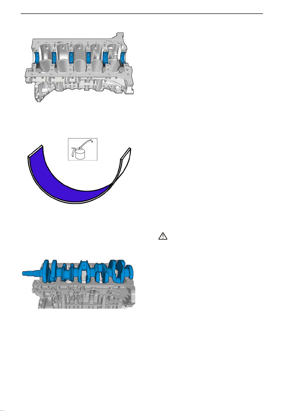
37 IMPORTANT!
Clean the components thoroughly before installation.
Install the crankshaft bearings in the cylinder
block.
38
Apply engine oil to the bearing races.
P0014665
P0014662
39
CAUTION!
Heavy
object. Use lifting device when installing or
removing.
IMPORTANT!
Clean the components thoroughly before installation.
Install the crankshaft.
36 47702022 12-2011
Page 39
21-0 Engine Complete, General
P0014661
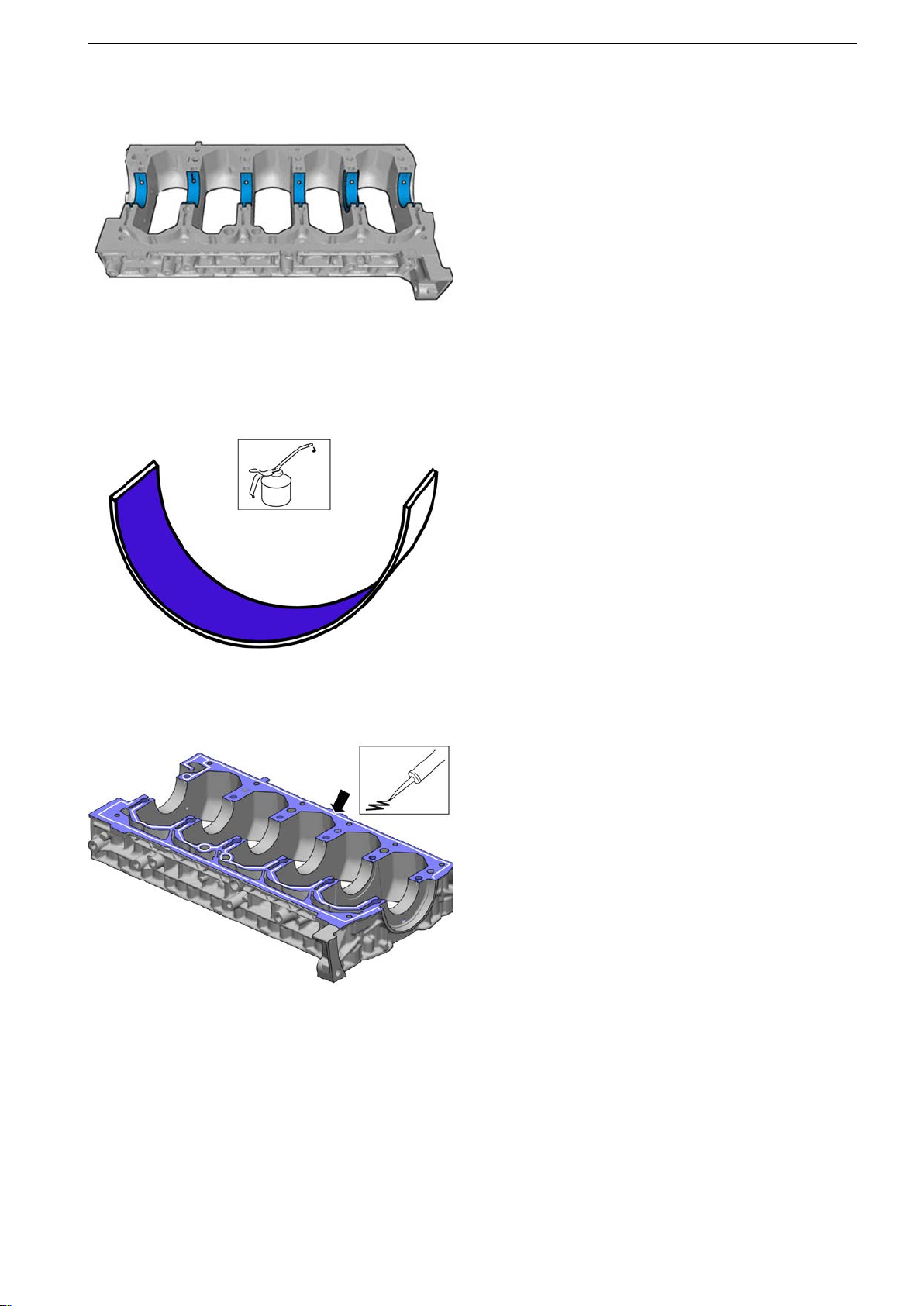
40 Install
the crankshaft bearings in the intermediate
section.
41 Apply engine oil to the bearing races.
P0014665
P0014666
42 NOTICE! Make sure the surface is clean before
application.
NOTICE! Components must be installed within
the specified time after application of sealant.
Apply sealant with a thickness of 1.5 mm (0.06")
to the intermediate section. Use sealant part #
1161771.
Install within 5 minutes.
47702022 12-2011 37
Page 40
21-0 Engine Complete, General
P0014660
43 Install the intermediate section.
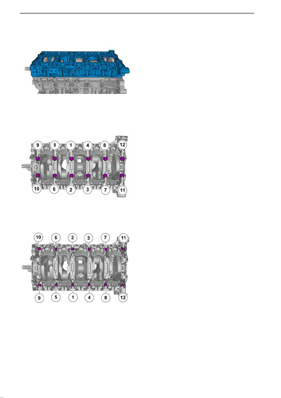
44
Install the bolts for the crankshaft section.
Tightening torque intermediate section to engine block:
P0014667
Step 1: 20 Nm (14.8 lbf.ft.)
Step 2: 40 Nm (29.5 lbf.ft.)
45 Install the bolts.
Tightening torque intermediate section to engine block:
Step 3: 24 Nm (17.7 lbf.ft.)
P0014668
38 47702022 12-2011
Page 41
P0014669
21-0 Engine Complete, General
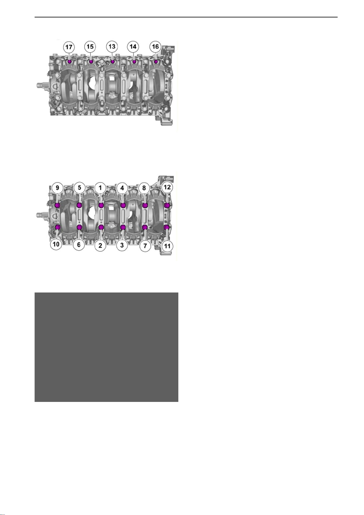
46 Install the bolts.
Tightening torque intermediate section to engine block:
Step 4: 17 Nm (12.5 lbf.ft.)
47
Final tightening, crankshaft section.
Tightening torque intermediate section to engine block:
P0014667
Step 5: 110°
48 Make sure the piston rings are installed with
120°displacement and that the gaps are not
directly above the piston pin.
P0014670
47702022 12-2011 39
Page 42
21-0 Engine Complete, General
P0014671
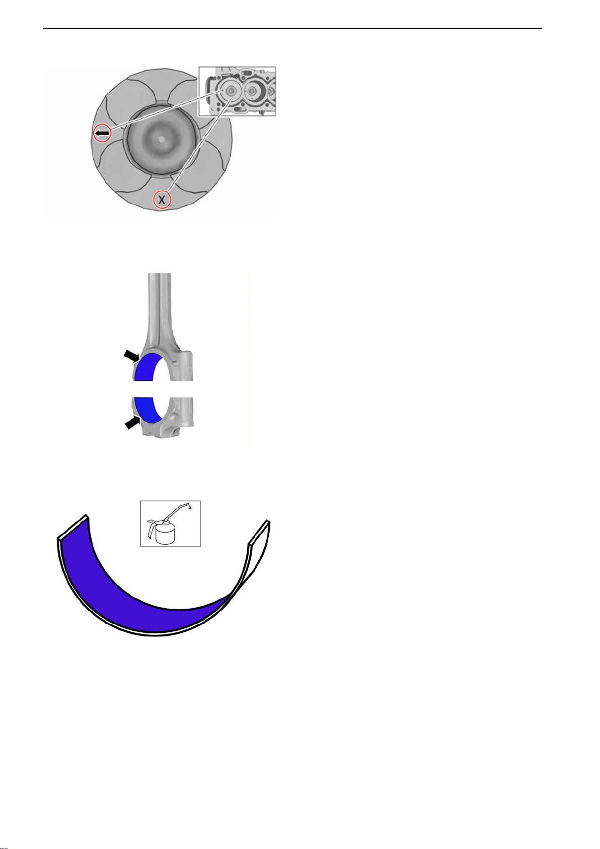
49 Make
sure the pistons are installed as illustrated.
Marking X = 1. cylinder bore classification
50 Install the connecting rod bearings.
P0014672
P0014665
51 Apply engine oil to the bearing races.
40 47702022 12-2011
Page 43
21-0 Engine Complete, General
P0014673
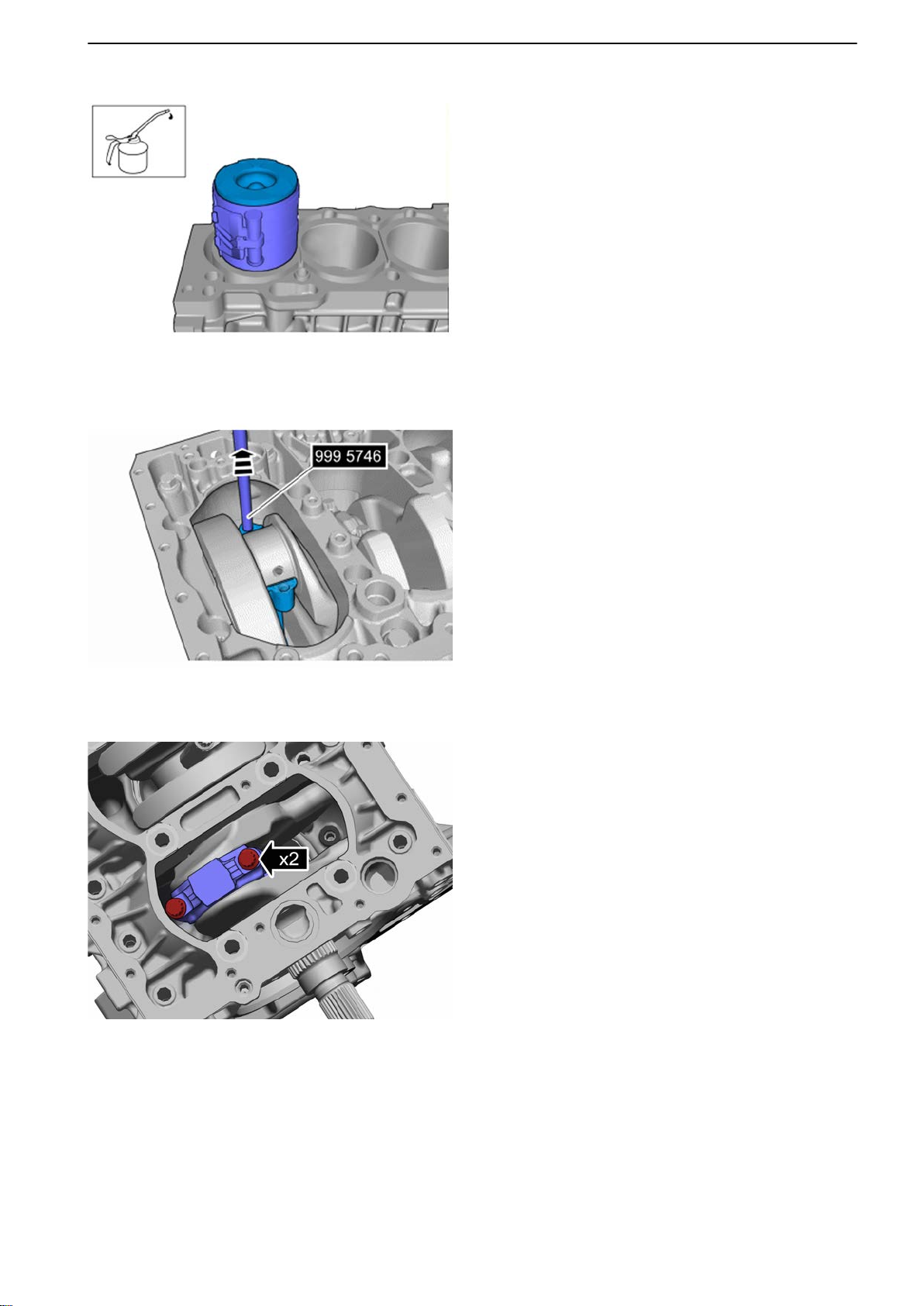
52 Crank
the crankshaft until cylinder # 1 is at bottom
dead center.
Put the piston in a piston ring compressor.
53 Install the piston together with the connecting rod.
Use 9995746 Puller.
P0014674
P0014655
54 IMPORTANT!
Take care with contact surfaces.
Install the bearing cap for cylinder # 1 connecting
rod.
Tightening torque:
Step 1: 30 Nm (22.1 lbf.ft.)
Step 2: 90°
47702022 12-2011 41
Page 44
21-0 Engine Complete, General
P0014654
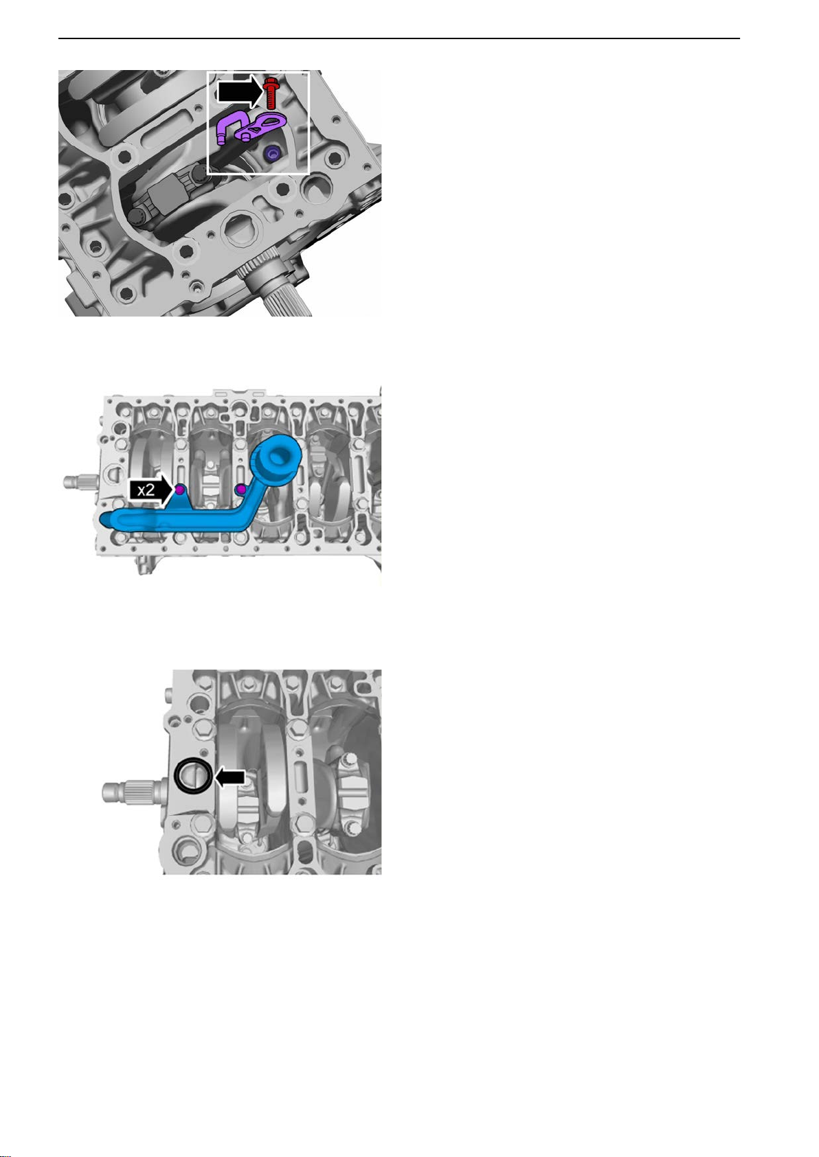
55 Install cylinder # 1 piston cooling nozzle.
Tightening torque: M6, 10 Nm (7.4 lbf.ft.)
56
Repeat the above procedure for cylinders 2-5.
57 Install the suction strainer.
Tightening torque: M7, 17 Nm (12.5 lbf.ft.)
P0014653
P0014675
58 Install the seal ring.
42 47702022 12-2011
Page 45
P0014676
21-0 Engine Complete, General
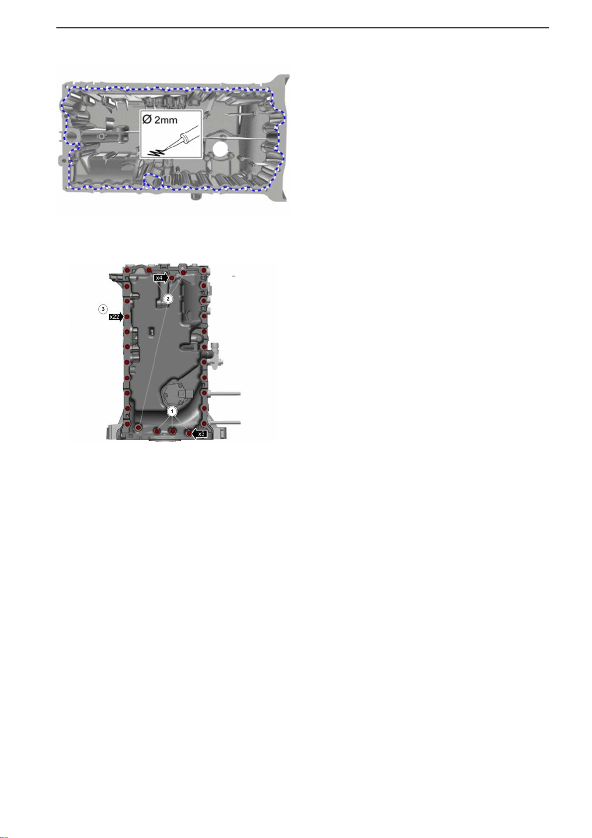
59 NOTICE! Make sure the surface is clean before
application.
NOTICE! Components must be installed within
the specified time after application of sealant.
Apply
sealant with a thickness of 2 mm (0.08") to
the intermediate section. Use sealant part #
1161771.
Install within 5 minutes.
60 Fit the oil sump.
Tightening torque: M7, 17 Nm (12.5 lbf.ft.)
1 M7, 70 mm (2.76")
P0014652
2 M7, 40 mm (1.58")
3 M7, 20 mm (0.79")
61 Install in reverse order.
47702022 12-2011 43
Page 46
21-0 Engine Complete, General
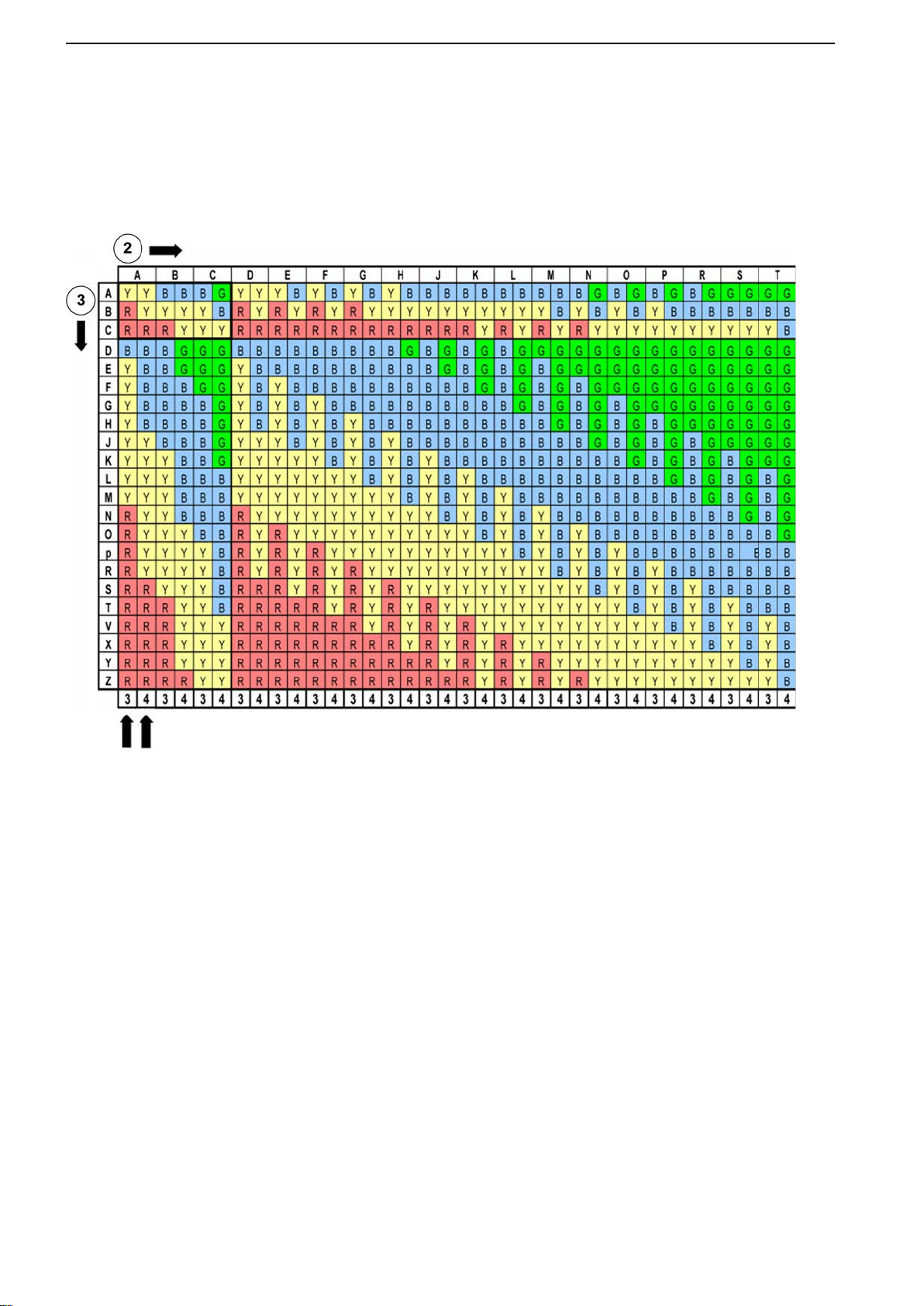
Engine Assembly
Classification schedule, cylinder block / crankshaft
2. Classification, cylinder block
3. Classification, crankshaft
4. Cylinder block
5. Intermediate section
Example
marking on the block at bearing position 2 is B. The
The
marking on the crankshaft at the corresponding bearing
position is C. This means the bearing in the block is
marked red and the one in the intermediate section is
marked yellow.
44 47702022 12-2011
Page 47
21-1 Cylinder Head
21-1 Cylinder Head
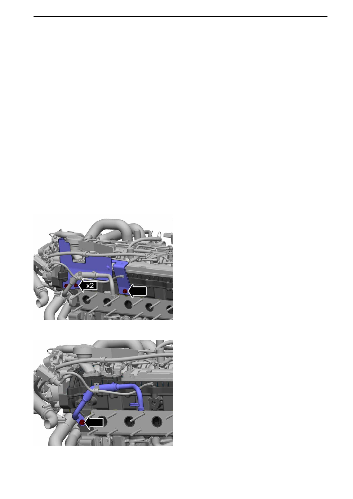
Cylinder Head, Change
Tools:
9989876 Dial indicator
9992767 Roller
9995192 Gauge rod
9995199 Drift
9995919 Extractor
9997005 Rotation tool
9997007 Lock pin
9997217 Wrench
Actions before working in boats; refer to: Actions
before working in boat page
Top cover service position; refer to: Top Cover, Service
Position page 69.
Remove the camshaft belt; refer to: Camshaft Belt,
Change page 73.
Remove the exhaust manifold; refer to: Exhaust Manifold, Change page 111.
20.
P0014358
Removal
1 Remove the heat shield.
2 Remove the coolant hose between the cylinder
head and the exhaust manifold.
3 Remove the heat exchanger; refer to: Heat
exchanger, change page 123.
4 Remove the high pressure pump; refer to: High
Pressure Pump, Change page 99.
P0014359
47702022 12-2011 45
Page 48
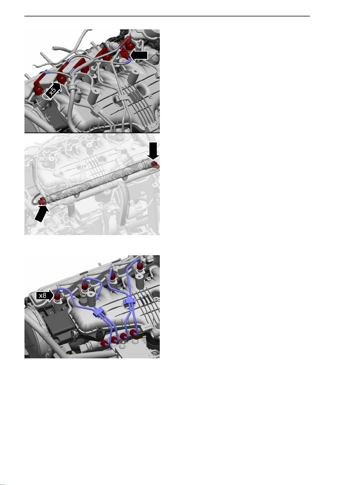
21-1 Cylinder Head
5 Remove the wire harness:
-
Injectors
- Camshaft sensors
- Rail pressure sensor
- PCV valve
P0014360
P0014361
6 Remove the delivery pipes.
Use 9997217 Wrench.
46 47702022 12-2011
Page 49
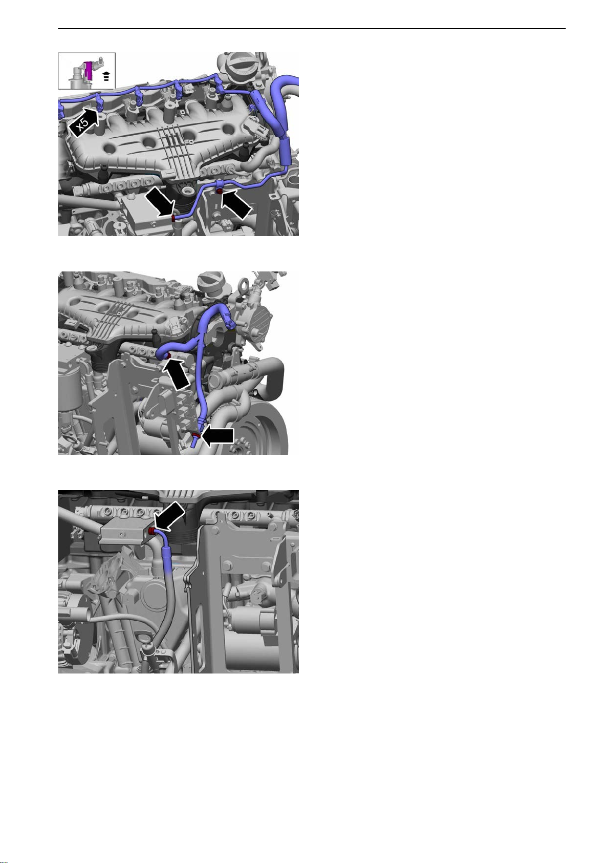
P0014362
21-1 Cylinder Head
7 Remove the fuel leak-off line incl. fuel supply
hose.
8
Remove the return line.
9 IMPORTANT!
The injectors are calibrated; in order to avoid
recalibration note the injector locations.
Remove the injectors; refer to: Injector, Cylinder
1-4, Change page 101.
P0014363
10 Remove the fuel filter; refer to: Engine Fuel Filter
Replacement page 92.
11 Remove the supply hose from the fuel filter
bracket.
P0014364
47702022 12-2011 47
Page 50
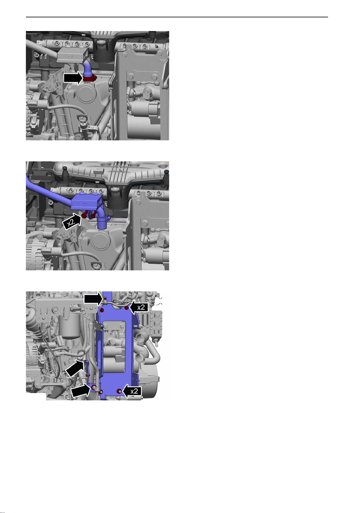
P0011331
21-1 Cylinder Head
P0014365
12 Remove the crankcase ventilation hose.
P0014366
13 Remove
the fuel filter bracket including the crank
case ventilation hose.
14 Remove the heat exchanger bracket.
48 47702022 12-2011
Page 51
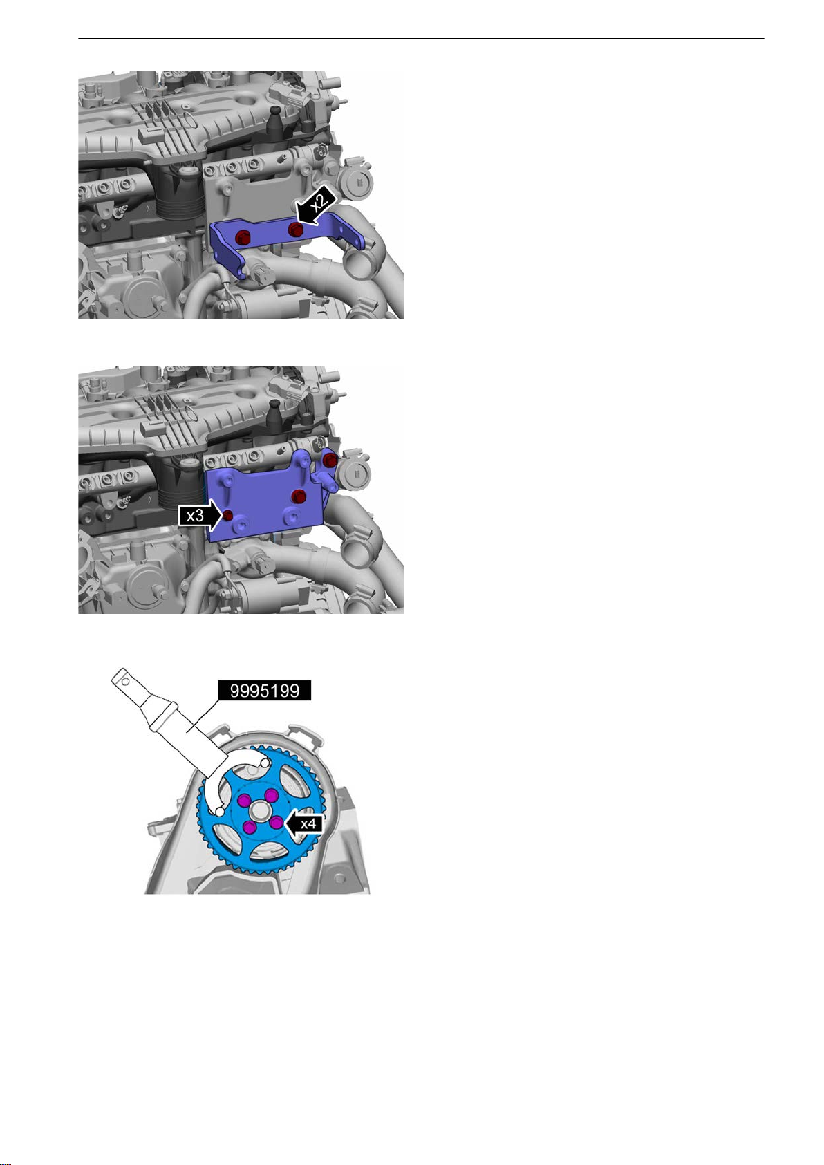
P0014367
15 Remove the attachment fitting.
16
Remove the attachment fitting bracket.
21-1 Cylinder Head
P0014368
P0014369
17 IMPORTANT!
Note the location of the components.
Remove the camshaft drive gear.
Use 9995199 Drift.
47702022 12-2011 49
Page 52
21-1 Cylinder Head
P0014370
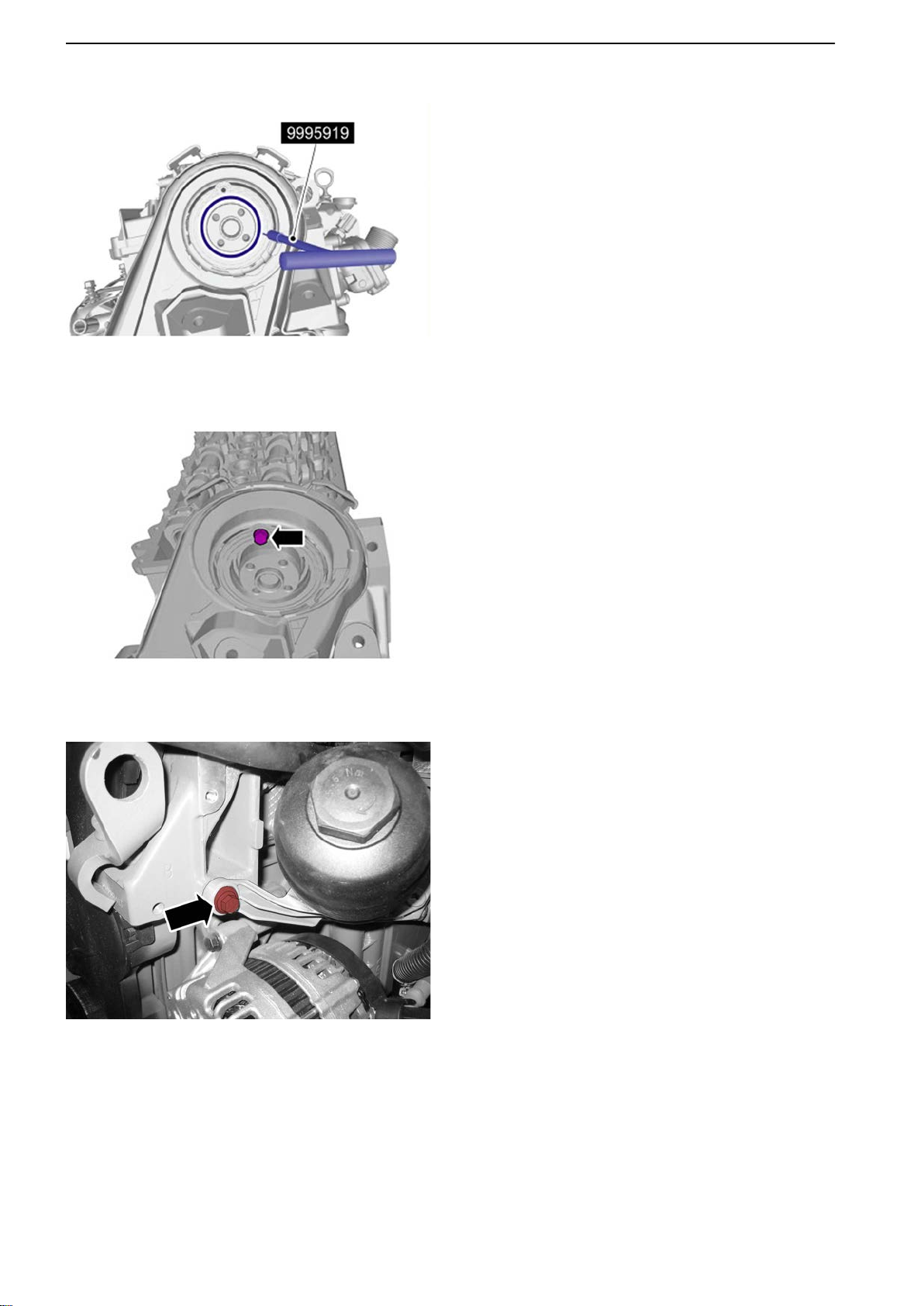
18 Remove the camshaft seal.
Use 9995919 Extractor
.
19 Remove the belt guard.
P0014371
P0014372
20 Remove the oil filter housing from the cylinder
head.
50 47702022 12-2011
Page 53
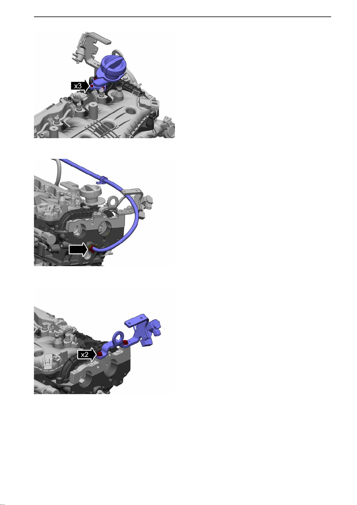
P0014373
21-1 Cylinder Head
21 Remove the oil filler pipe.
22
Remove the vacuum pump; refer to: Vacuum
Pump, Change page 118.
23 Remove the venting hose at the back of the cyl-
inder head.
P0014374
P0014375
24 Remove the rear lifting lug.
47702022 12-2011 51
Page 54
21-1 Cylinder Head
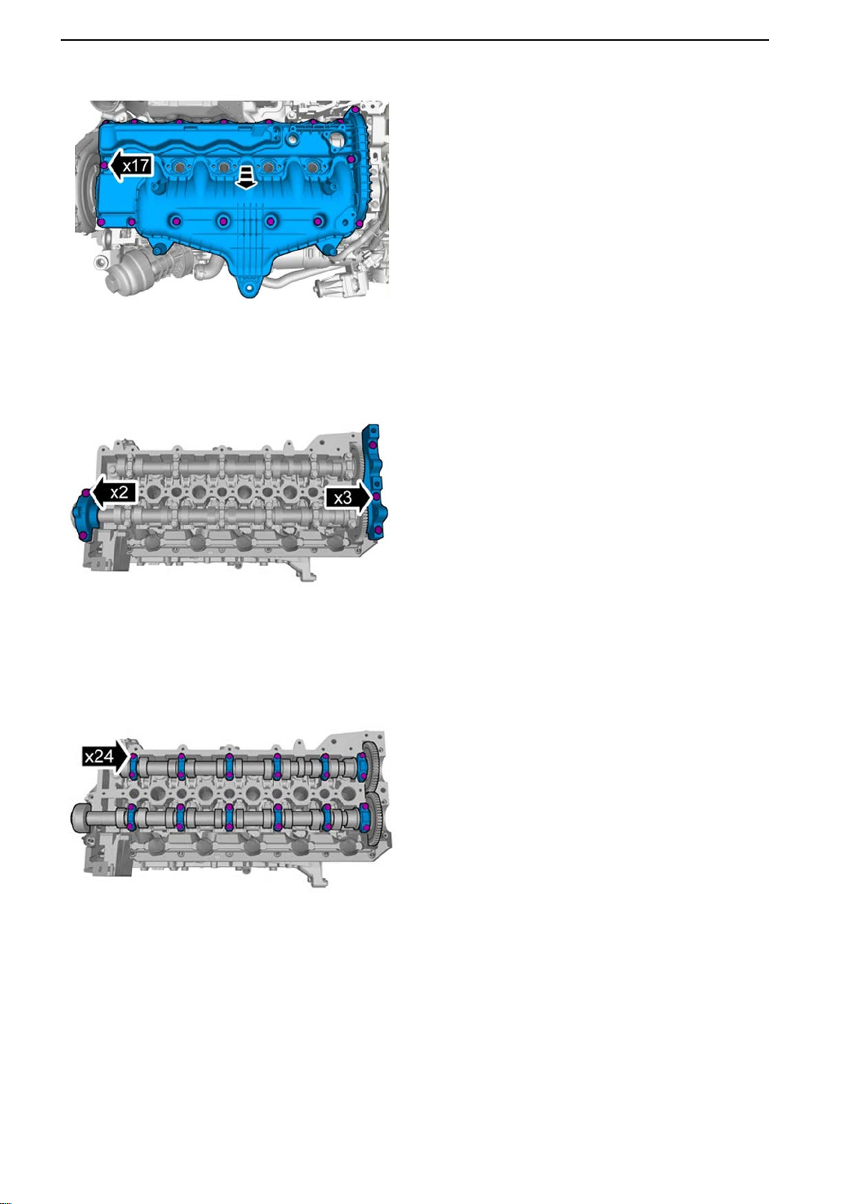
P0014376
25 Remove the inlet manifold.
26
Remove the bearing caps.
P0014377
P0014378
27 IMPORTANT!
Note the location of the components.
Remove the camshaft bearing caps.
52 47702022 12-2011
Page 55
P0014379
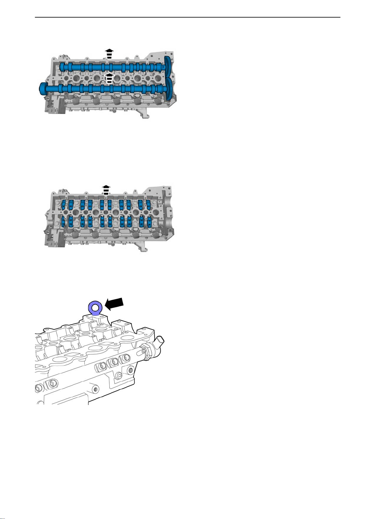
21-1 Cylinder Head
28 Remove the camshafts.
29 IMPORTANT!
Note the location of the components.
Remove the lifters.
P0014380
P0014381
30
Install a lifting lug.
47702022 12-2011 53
Page 56
P0011332
21-1 Cylinder Head
P0014382
31 Remove the cylinder head.
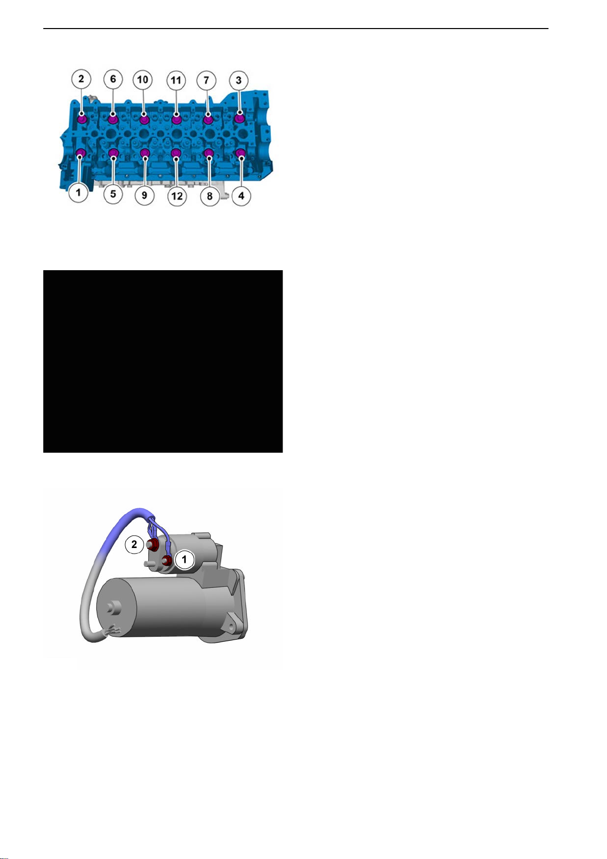
32
Remove the cylinder head gasket. Note the gasket category.
P0014383
33 Undo the starter motor connections.
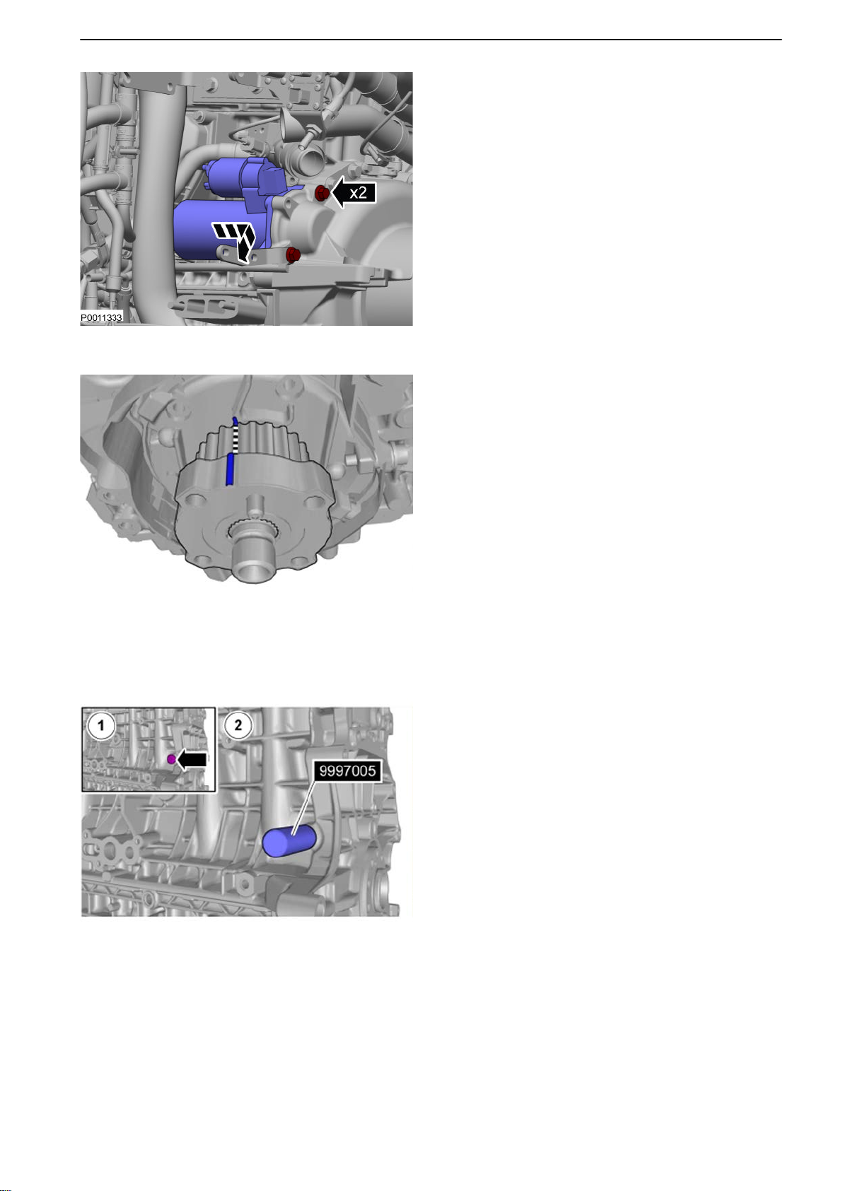
1 B+ (30)
2 Start supply (50)
54 47702022 12-2011
Page 57
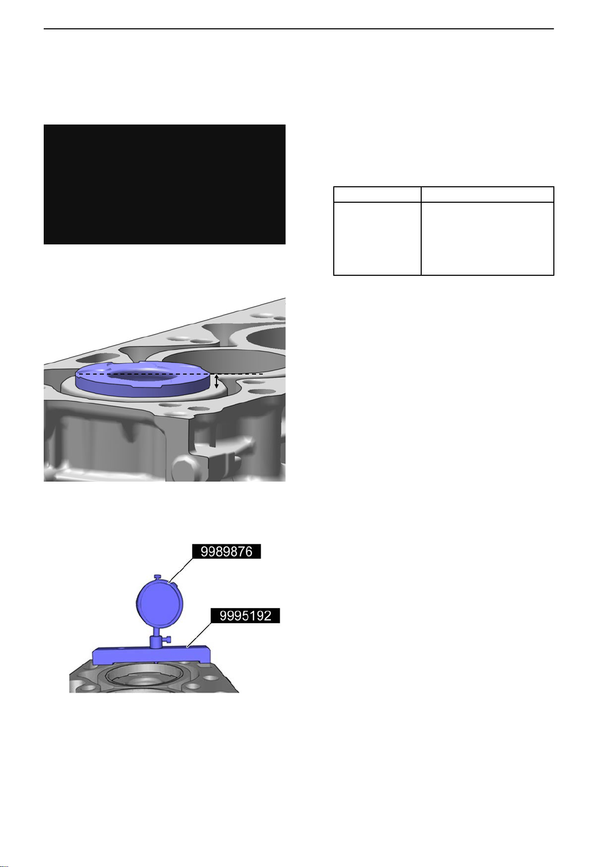
P0011333
21-1 Cylinder Head
34 Remove the starter motor.
35 IMPORTANT!
Make sure the camshaft is at TDC.
IMPORTANT!
The crankshaft may only be rotated clockwise.
P0014384
P0014385
36 IMPORTANT!
Make sure the camshaft is at TDC.
Use 9997005 Rotation tool
.
47702022 12-2011 55
Page 58
21-1 Cylinder Head
Installation
P0015855
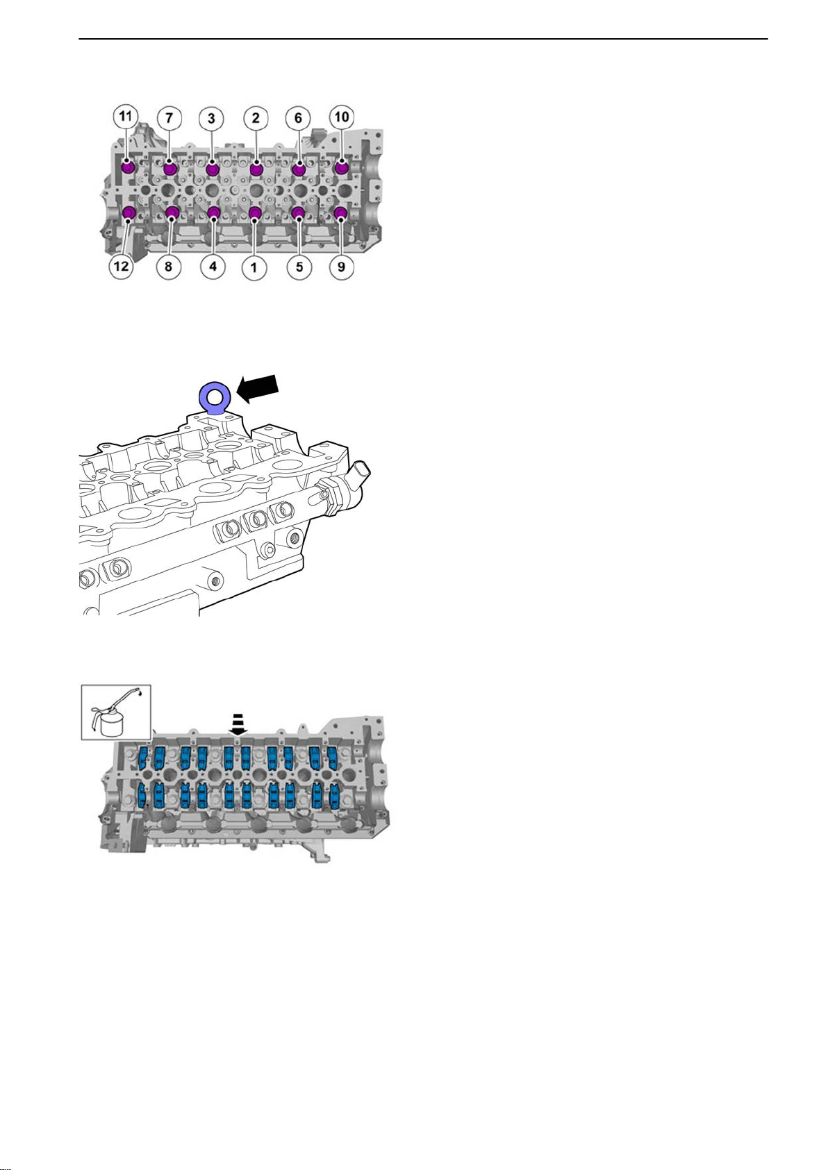
37 NOTICE! The
type of gasket is identified as illus-
trated.
Install cylinder head gasket.
NOTICE! Hole
A and B are only used to identify
engine type and therefore will not affect the classification.
Classification Hole marking
1 5
2 4, 5
3 3, 4, 5
4 2, 3, 4, 5
5 1, 5
NOTICE!
Classification must be performed if cyl-
inder block has been replaced.
P0015856
P0015857
Use 9995192 Gauge rod and 9989876 Dial indicator.
Reset 9989876 Dial indicator
against the block
surface.
Rotate the engine so that the piston reaches
TDC, use 9997005 Rotation tool .
To read out classification, compare measurement value towards Group 21: Engine, Cylinder
head gasket in Technical Data page 9.
56 47702022 12-2011
Page 59
P0014386
38 Install the cylinder head.
Use new cylinder head bolts.
Tightening torque:
Step 1: 20 Nm (14.8 lbf.ft.)
Step 2: Undo at least 360°
Step 3: 20 Nm (14.8 lbf.ft.)
Step 4: 50 Nm (36.9 lbf.ft.)
Step 5: 120°
Step 6: 120°
39
Remove the lifting lug.
21-1 Cylinder Head
P0014381
P0014387
40 Install the lifters.
47702022 12-2011 57
Page 60
21-1 Cylinder Head
P0014388
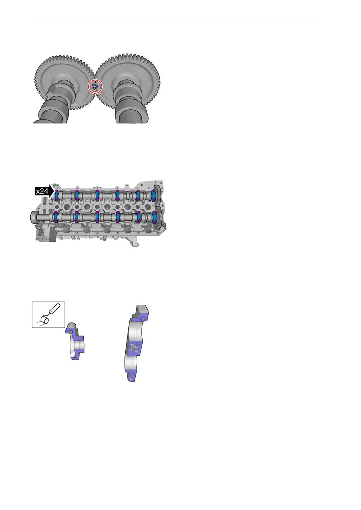
41 NOTICE! The camshafts may not be rotated.
Install the camshafts.
Install the bearing caps. Screw down the cam-
42
shafts alternately from the center outwards.
Tightening torque: M6, 10 Nm (7.4 lbf.ft.)
P0014378
P0014389
43 IMPORTANT!
Make sure the components are clean and free
from foreign objects and lubricants before application.
Apply sealant.
Use liquid gasket, part # 1161059.
Use 9992767 Roller.
58 47702022 12-2011
Page 61
P0014377
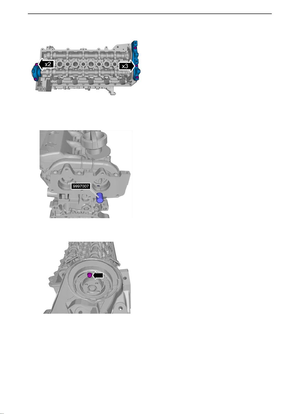
21-1 Cylinder Head
44 Tightening torque: M7, 17 Nm (12.5 lbf.ft.)
45
Install the camshaft seals.
46 Lock the camshafts in the zero position.
Use 9997007 Lock pin.
P0014390
P0014371
47 Install the belt guard bolt.
Tightening torque: M6, 10 Nm (7.4 lbf.ft.)
47702022 12-2011 59
Page 62
21-1 Cylinder Head
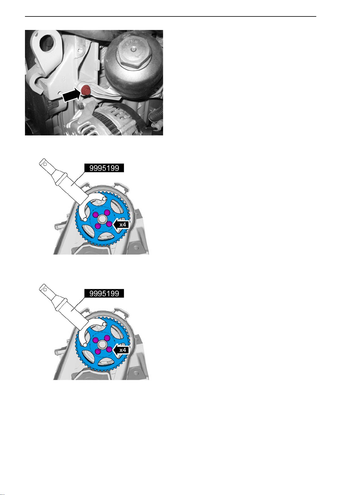
P0014372
48 Install
the attachment fitting for the oil filter hous-
ing.
Tightening torque: M6, 10 Nm (7.4 lbf.ft.)
49 Install the camshaft drive gear.
NOTICE! Only tighten by hand at this time.
50 Install the camshaft belt; refer to: Camshaft Belt,
Change page 73.
P0014369
P0014369
51 Tighten the drive gear.
Tightening torque: M7, 17 Nm (12.5 lbf.ft.)
60 47702022 12-2011
Page 63
P0014385
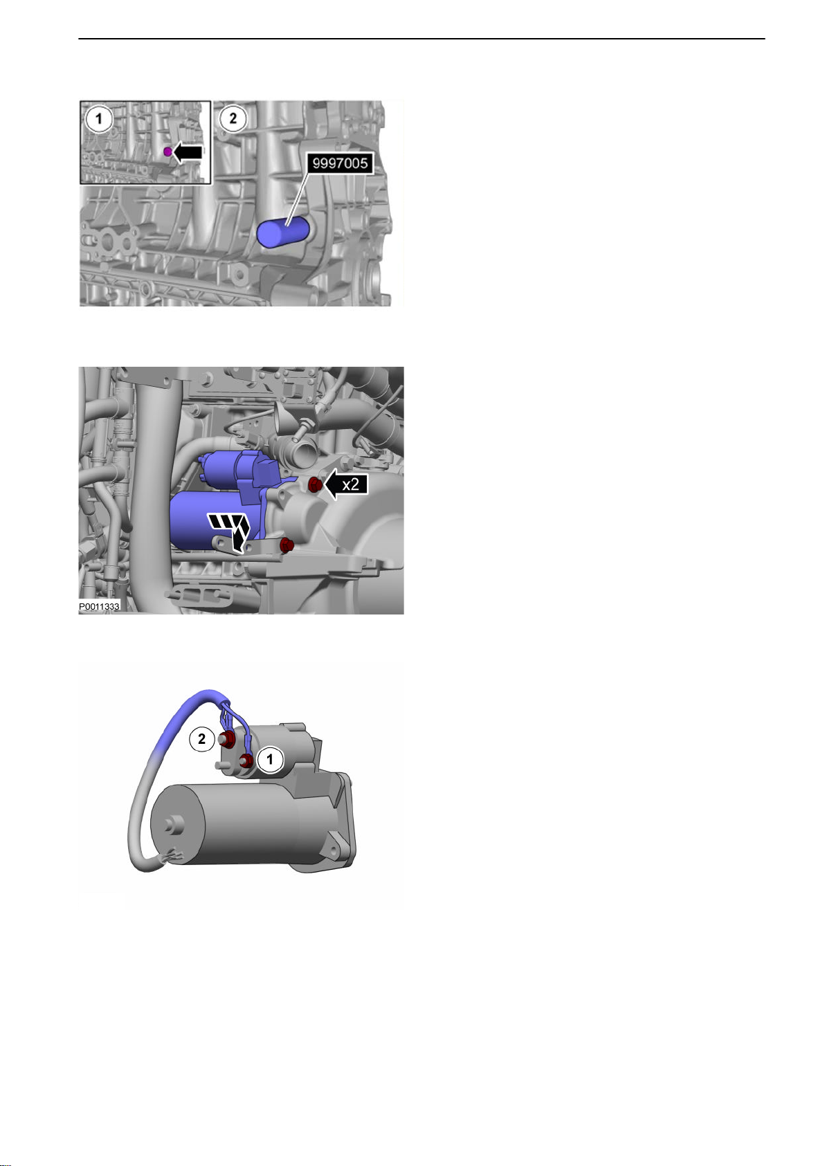
P0011333
P0011332
21-1 Cylinder Head
52 Remove the tool. Install the engine block plug.
Tightening torque: 38 Nm (28.0 lbf.ft.)
53
Install the starter motor.
Tightening torque: M10, 50 Nm (36.9 lbf.ft.)
54 Connect the starter motor contacts.
1 B+ (30)
Tightening torque: 11 Nm (8.1 lbf.ft.)
2 Start supply (50)
Tightening torque: 8.5 Nm (6.3 lbf.ft.)
47702022 12-2011 61
Page 64
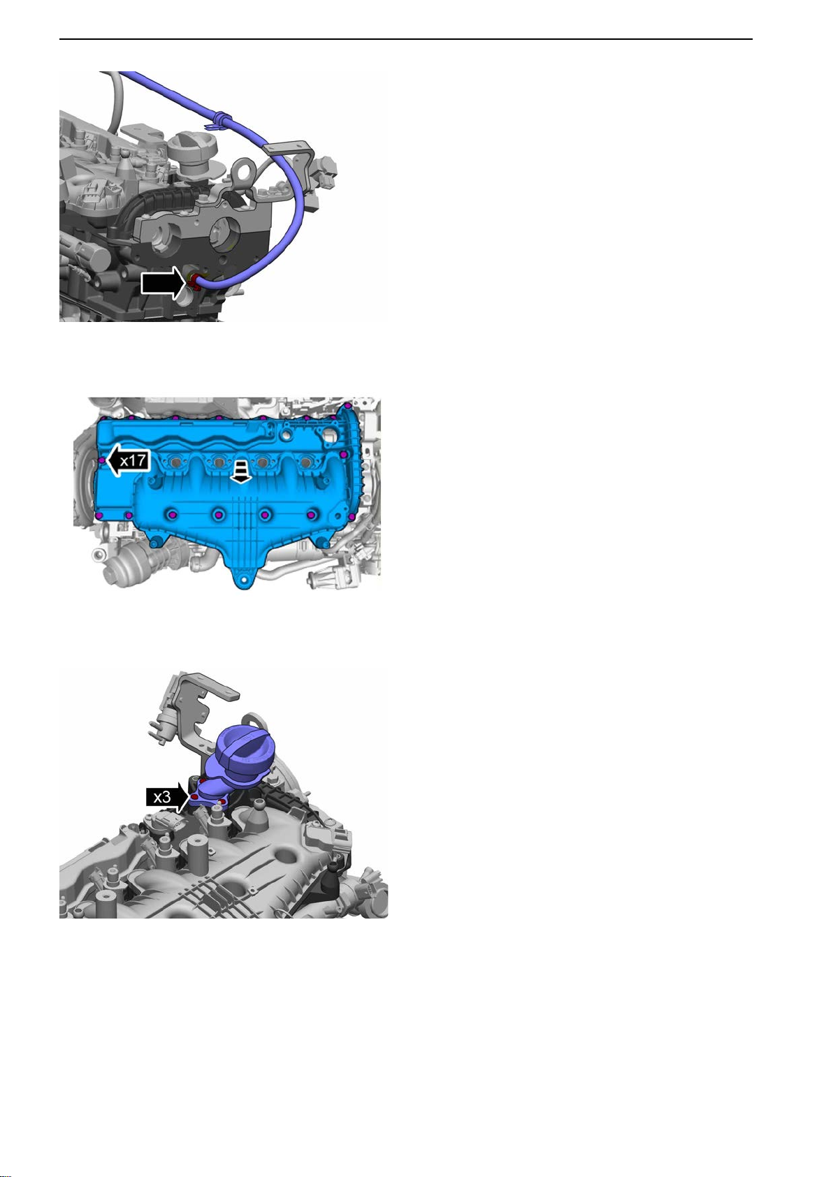
21-1 Cylinder Head
55 Install the cylinder head venting hose.
P0014374
56 Install
the vacuum pump; refer to: Vacuum Pump,
Change page 118.
57 Install the inlet manifold.
Tightening torque: M6, 10 Nm (7.4 lbf.ft.)
P0014376
P0014373
58 Install the oil filler pipe.
62 47702022 12-2011
Page 65
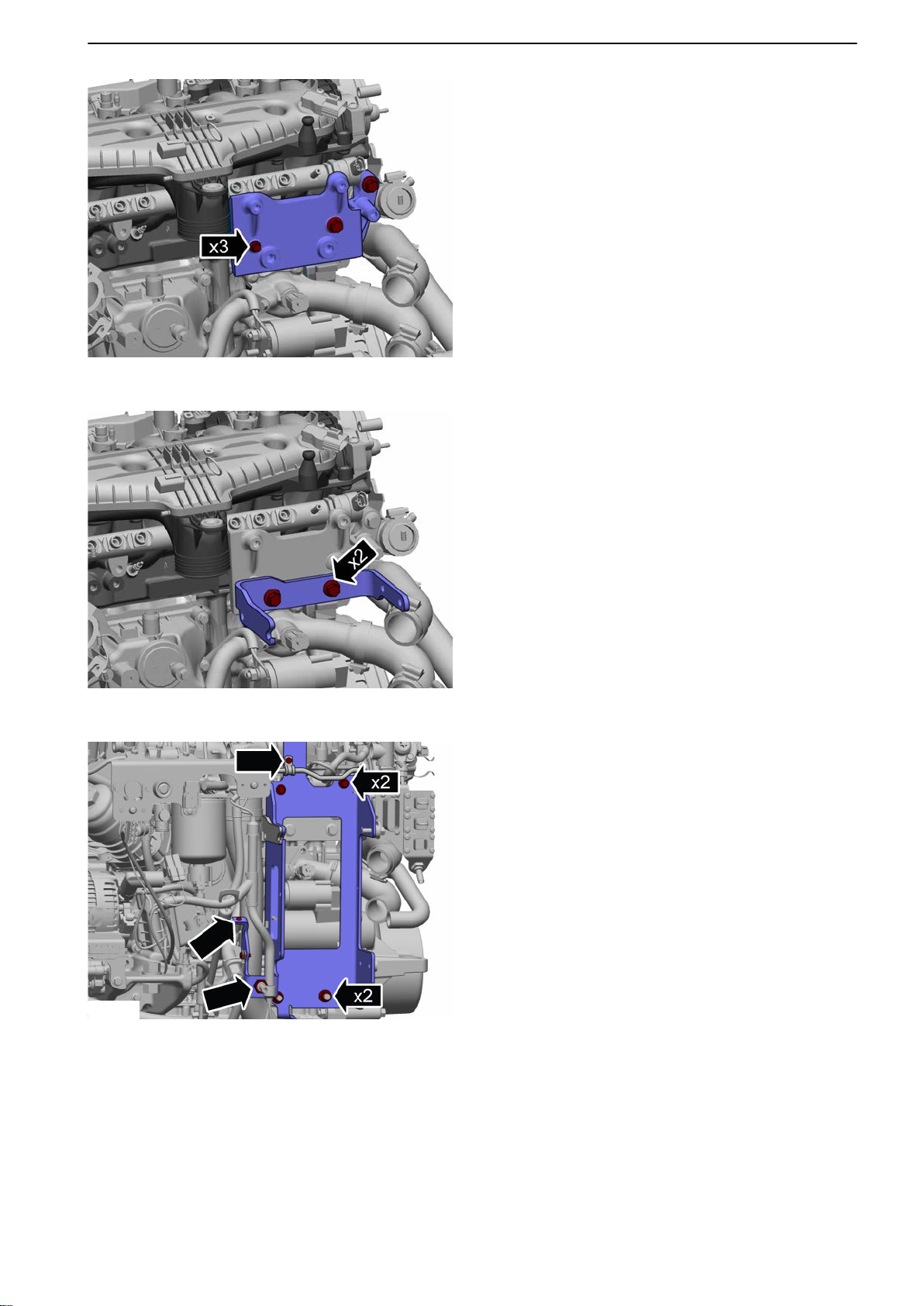
P0014368
P0011331
21-1 Cylinder Head
59 Install the attachment fitting bracket.
Tightening torque:
-
M8 24 Nm (17.7 lbf.ft.)
- M10 50 Nm (36.9 lbf.ft.)
60 Install the attachment fitting.
Tightening torque: M10, 50 Nm (36.9 lbf.ft.)
P0014367
61 Install the heat exchanger bracket.
Tightening torque:
- M6 10 Nm (7.4 lbf.ft.)
- M8 24 Nm (17.7 lbf.ft.)
- M10 48 Nm (35.4 lbf.ft.)
- Union nut: 38 Nm (28.0 lbf.ft.)
47702022 12-2011 63
Page 66
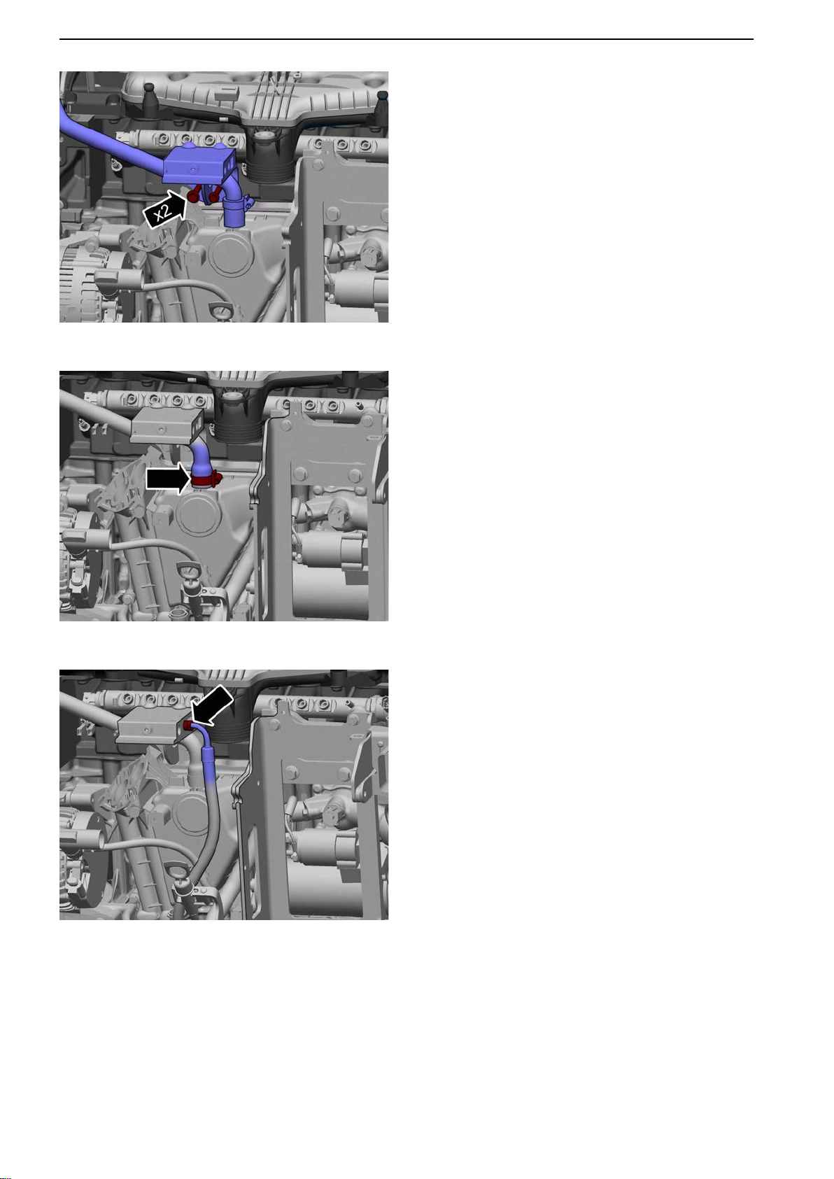
21-1 Cylinder Head
P0014366
62 Install the fuel filter bracket.
Tightening torque:
-
M6 10 Nm (7.4 lbf.ft.)
- M8 24 Nm (17.7 lbf.ft.)
63 Install the crankcase ventilation hose.
P0014365
P0014364
64 Connect the supply hose to the fuel filter bracket.
Tightening torque: 15 Nm (11.1 lbf.ft.)
65 Install the fuel filter; refer to: Engine Fuel Filter
Replacement page 92.
66 Install the injectors; refer to: Injector, Cylinder 1-4,
Change page 101.
64 47702022 12-2011
Page 67
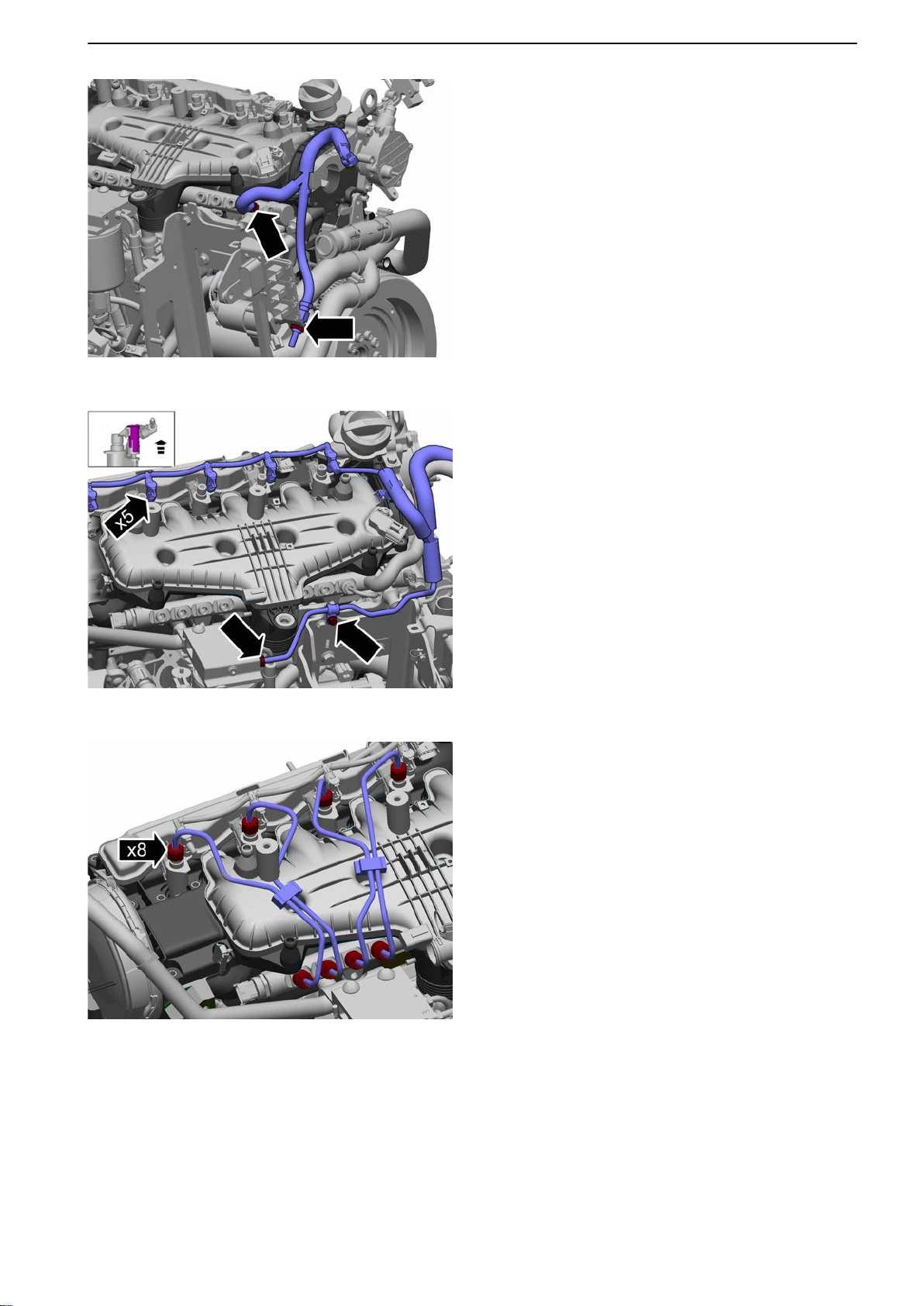
P0014363
21-1 Cylinder Head
67 Install the fuel return hose.
Tightening torque, union nut: 38
Nm (28.0 lbf.ft.)
68
Install the fuel leak-off line incl. fuel supply hose.
P0014362
P0014361
69 Install the delivery pipes, cylinders 1-4.
Tightening torque:
Step 1: 10 Nm (7.4 lbf.ft.)
Step 2: 60°
70 Install the high pressure pump; refer to: High
Pressure Pump, Change page 99.
47702022 12-2011 65
Page 68
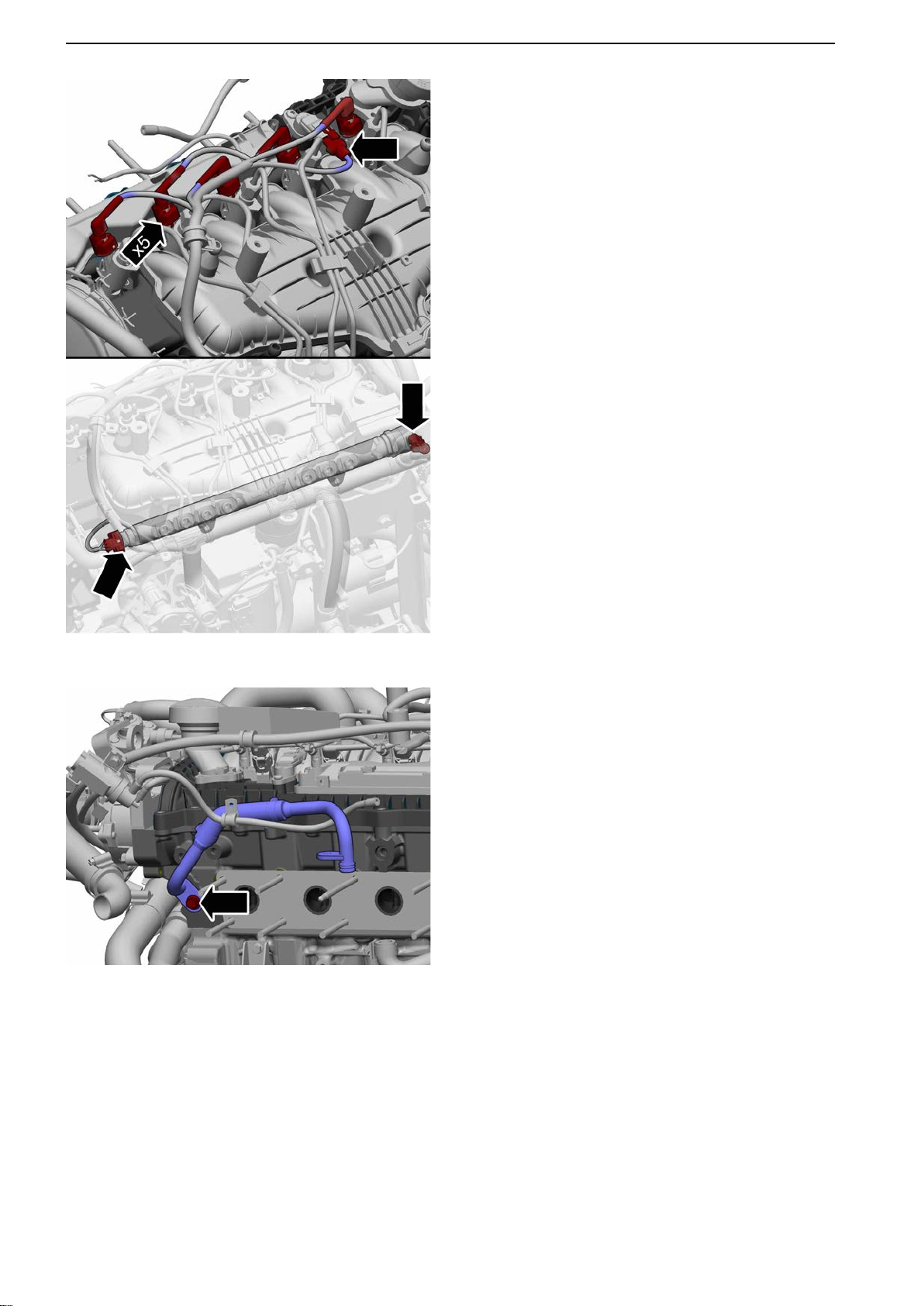
21-1 Cylinder Head
71 Install the wire harness:
-
Injectors
- Camshaft sensors
- Rail pressure sensor
- PCV valve
72 Install the heat exchanger; refer to: Heat
exchanger, change page 123.
P0014360
P0014359
73 Fit the hose between the cylinder head and
exhaust manifold.
Tightening torque: M8, 24 Nm (17.7 lbf.ft.)
66 47702022 12-2011
Page 69
P0014358
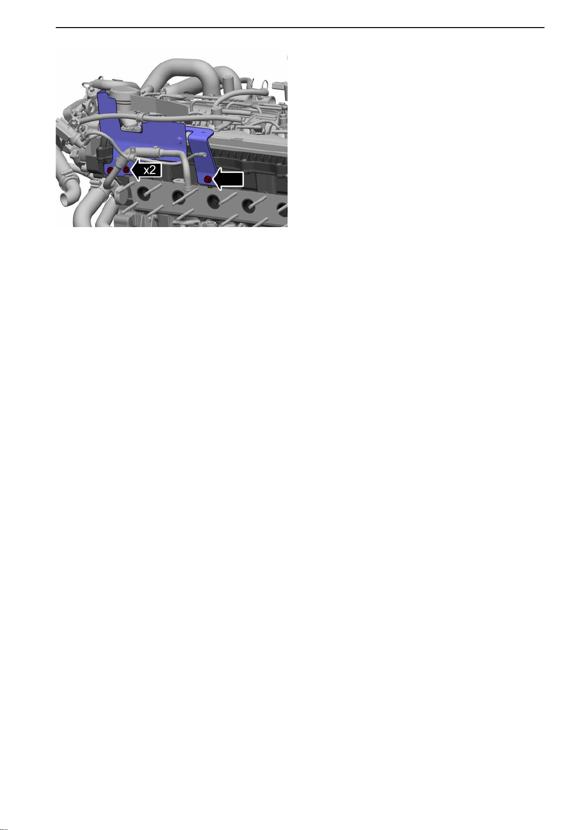
21-1 Cylinder Head
74 Install the heat shield.
Tightening torque:
-
M7 17 Nm (12.5 lbf.ft.)
- M8 24 Nm (17.7 lbf.ft.)
75 Install the exhaust manifold, turbocharger,
charge air cooler and seawater pump in the
reverse order described in Exhaust Manifold,
Change page 111.
76 Install the top cover; refer to: Top Cover, Service
Position page 69.
Finishing off
Make shipshape; refer to: Actions before working in
boat page 20.
47702022 12-2011 67
Page 70
P0011356
P0011357
P0011358
21-1 Cylinder Head
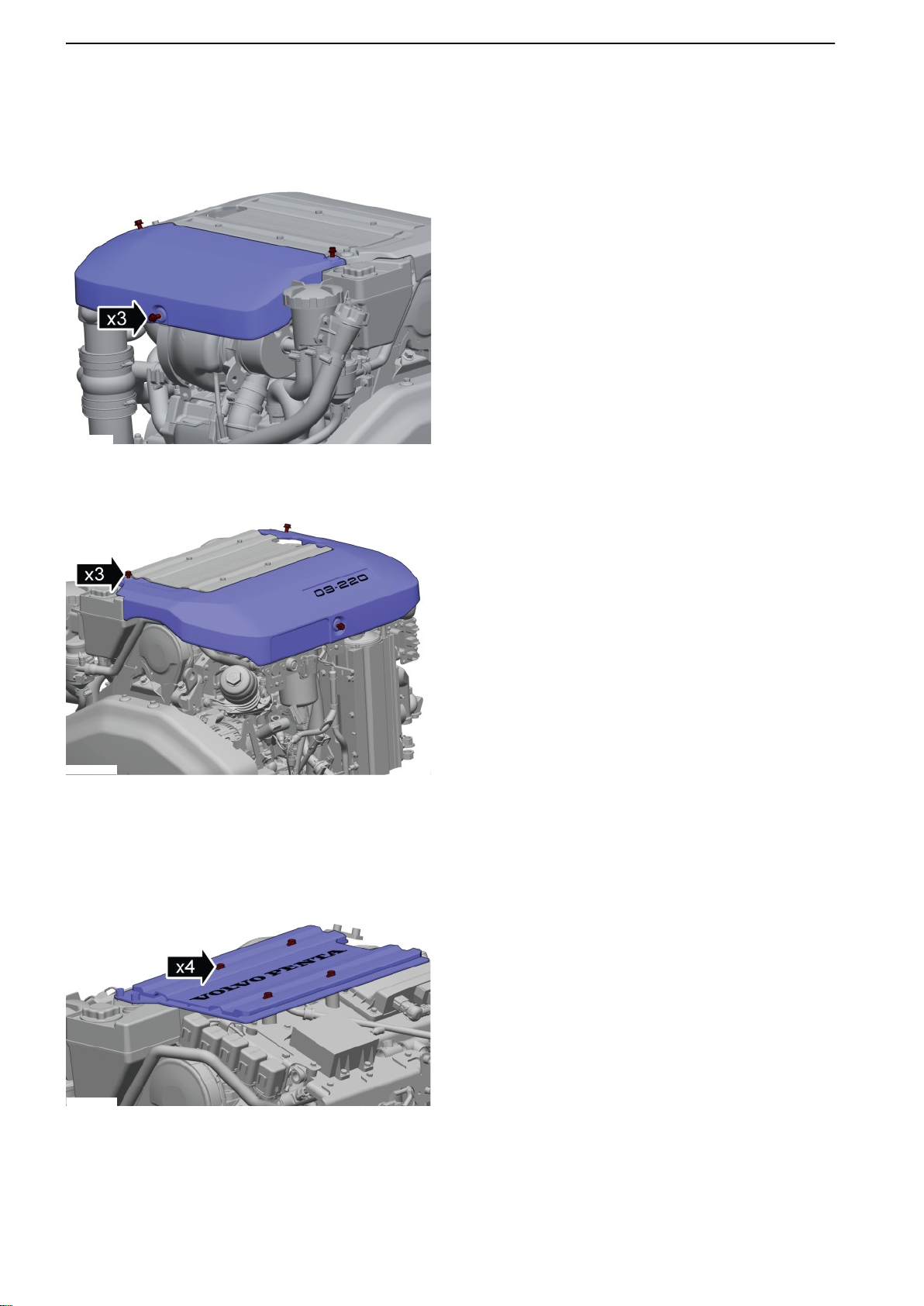
Engine Cover, replace
Removal
Remove the cover (hot side).
1
Tightening torque: M8, 24 Nm (17.7 Ibf.ft.)
2 Remove the cover (cold side).
Tightening torque: M8, 24 Nm (17.7 Ibf.ft.)
3 Remove the center cover.
Tightening torque: M8, 24 Nm (17.7 Ibf.ft.)
Installation
Install in reverse order.
68 47702022 12-2011
Page 71
P0011395
21-1 Cylinder Head
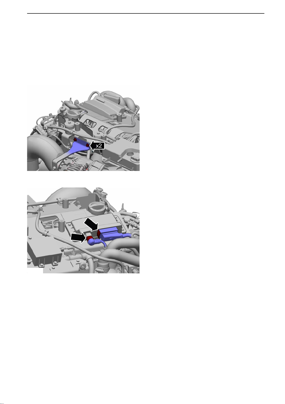
Top Cover, Service Position
Removal
NOTICE! Make sure system power is switched off.
Remove the engine covers according to: Engine
Cover, replace page
1 Remove the support bracket by the charge air
cooler.
68.
P0012179
2 Remove the steering unit (PCU) harness.
47702022 12-2011 69
Page 72
21-1 Cylinder Head
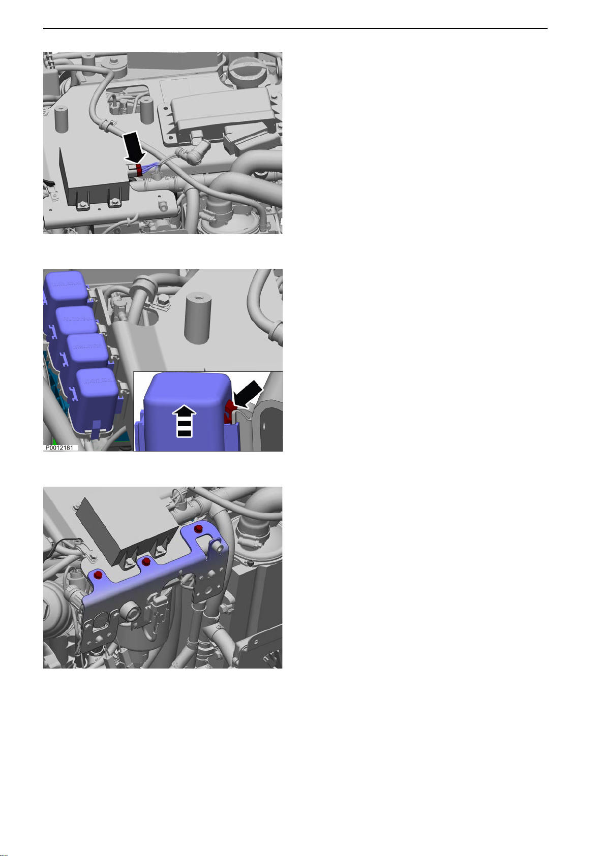
P0012180
3 Remove the DC/DC transducer cables.
4
Remove all relays.
P0012182
5 Remove the bracket.
70 47702022 12-2011
Page 73
P0012183
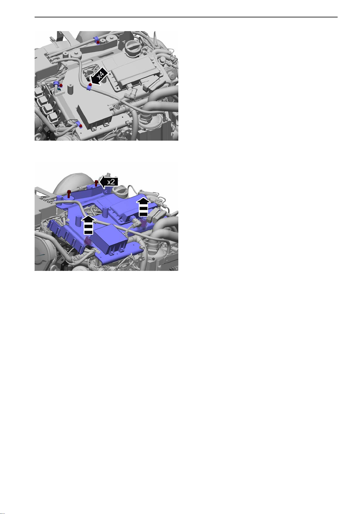
21-1 Cylinder Head
6 Remove the attachment fittings (4 pcs.) from the
venting hoses.
7
Remove the top plate.
Remove the top plate by pulling it up and to one
side.
P0012184
Installation
Install in reverse order.
47702022 12-2011 71
Page 74
P0005675
P0006980
P0005677
21-5 Timing Gears and Shaft
21-5 Timing Gears and Shaft
Gear Ring, Replace
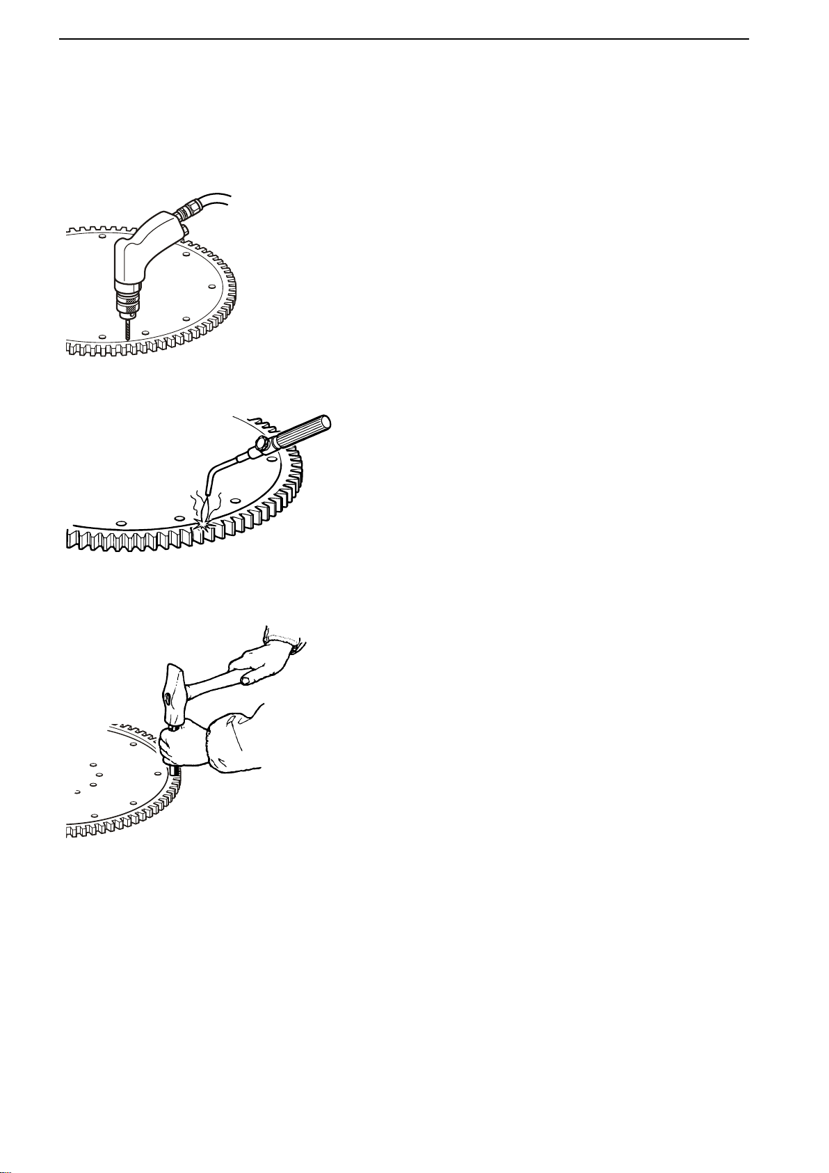
Flywheel removed.
1
2 Brush the flywheel contact surface clean with a
Drill 1–2 holes between teeth on ring gear.
Use a cold chisel to split the ring gear at the drill
site and remove the ring.
steel wire brush.
Heat the new ring gear in an oven or with a welding torch to max 180-200 °C (356-392 °F).
IMPORTANT!
Take care to ensure that the ring gear is evenly
heated with no hot spots that may lead to annealing. Polish the ring gear in a number of places
before heating begins to aid controlling the heating process. Stop heating when these surfaces
become blued.
3 Fit the heated ring gear onto the flywheel and tap
it into place with a soft mandrel and hammer.
Let the ring gear cool in the open air.
4 Install the flywheel.
72 47702022 12-2011
Page 75
P0011241
P0011242
21-5 Timing Gears and Shaft
Camshaft Belt, Change
Tools:
885633 Torque multiplier
885819 Counterhold
Removal
Remove the drive belt according to: Drive Belt,
Change page
Remove the engine cover (cold side) according to:
Engine Cover, replace page 68.
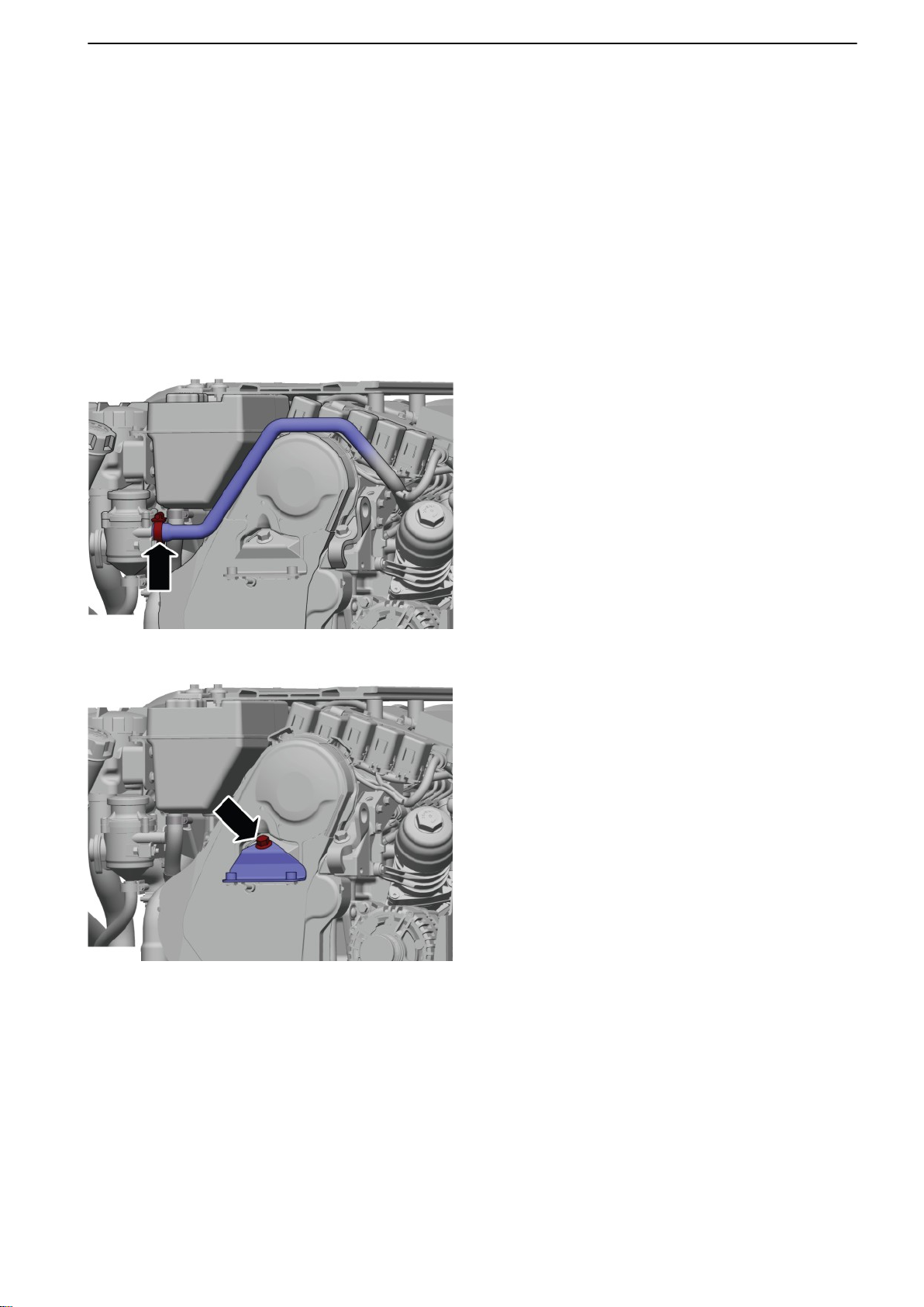
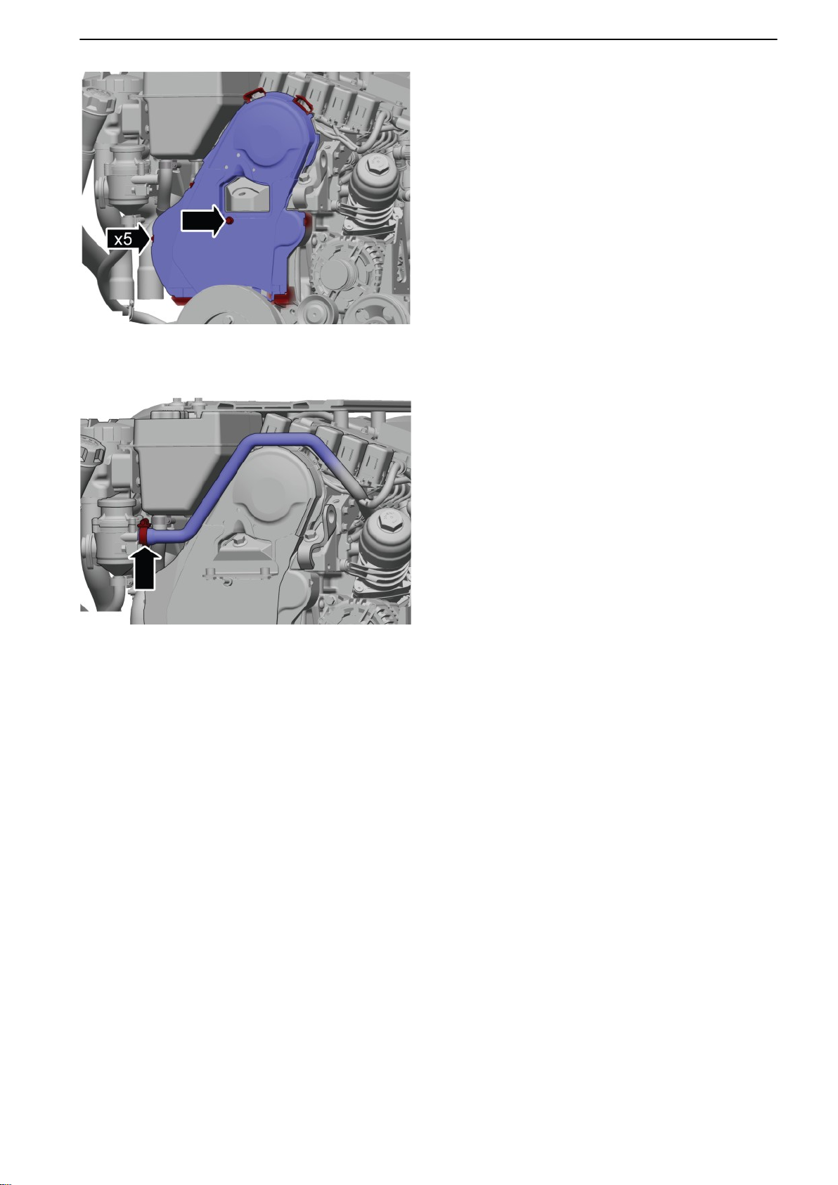
1 Remove the crankcase ventilation hose.
129.
2 Remove the bracket.
47702022 12-2011 73
Page 76
P0011243
P0011244
P0011247
21-5 Timing Gears and Shaft
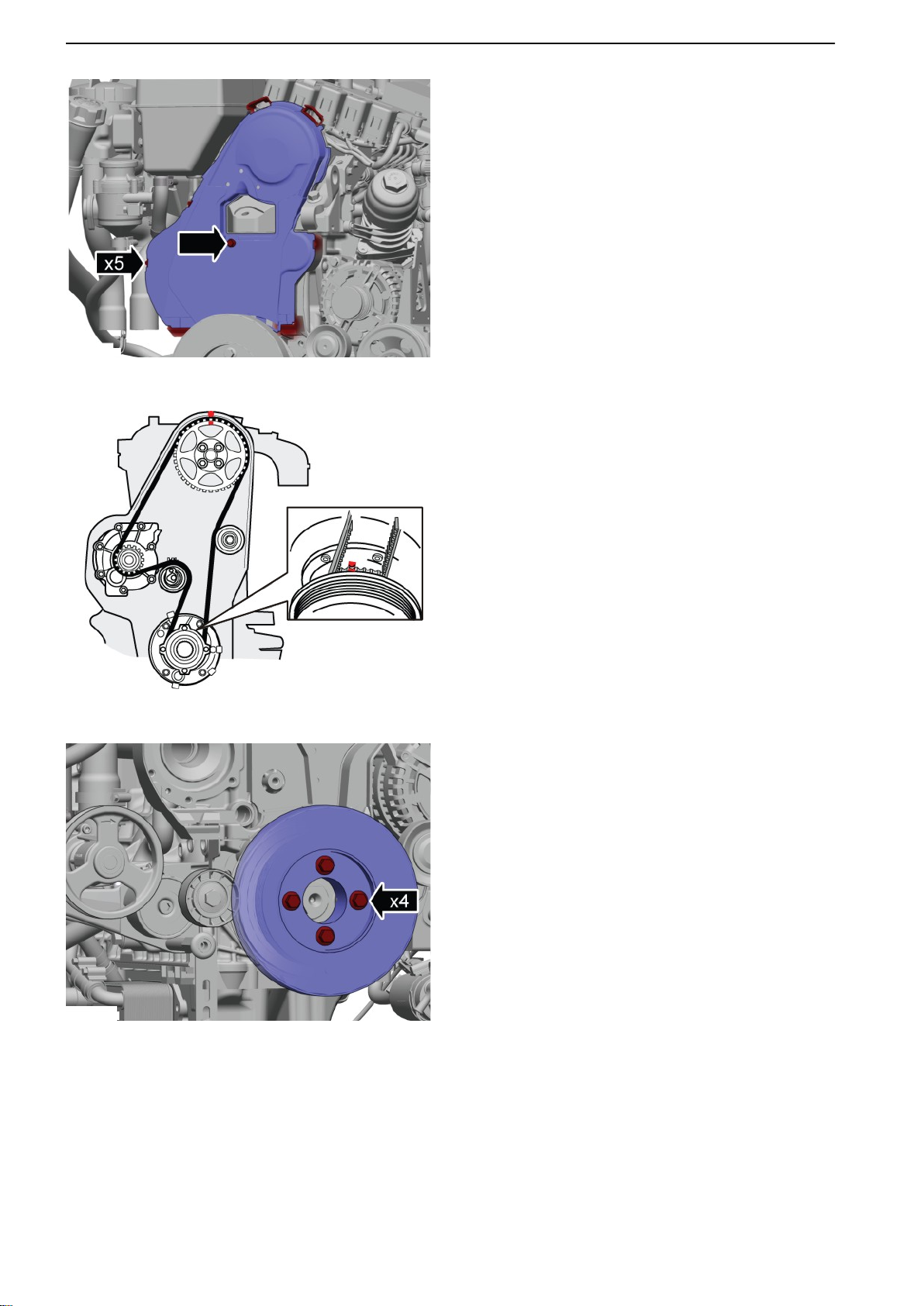
3 Remove the cover.
4 Set
up the engine so that the camshaft and crankshaft markings are aligned to the marks on the
engine.
5 Lift away the vibration damper.
74 47702022 12-2011
Page 77
P0011248
P0011249
P0011250
21-5 Timing Gears and Shaft
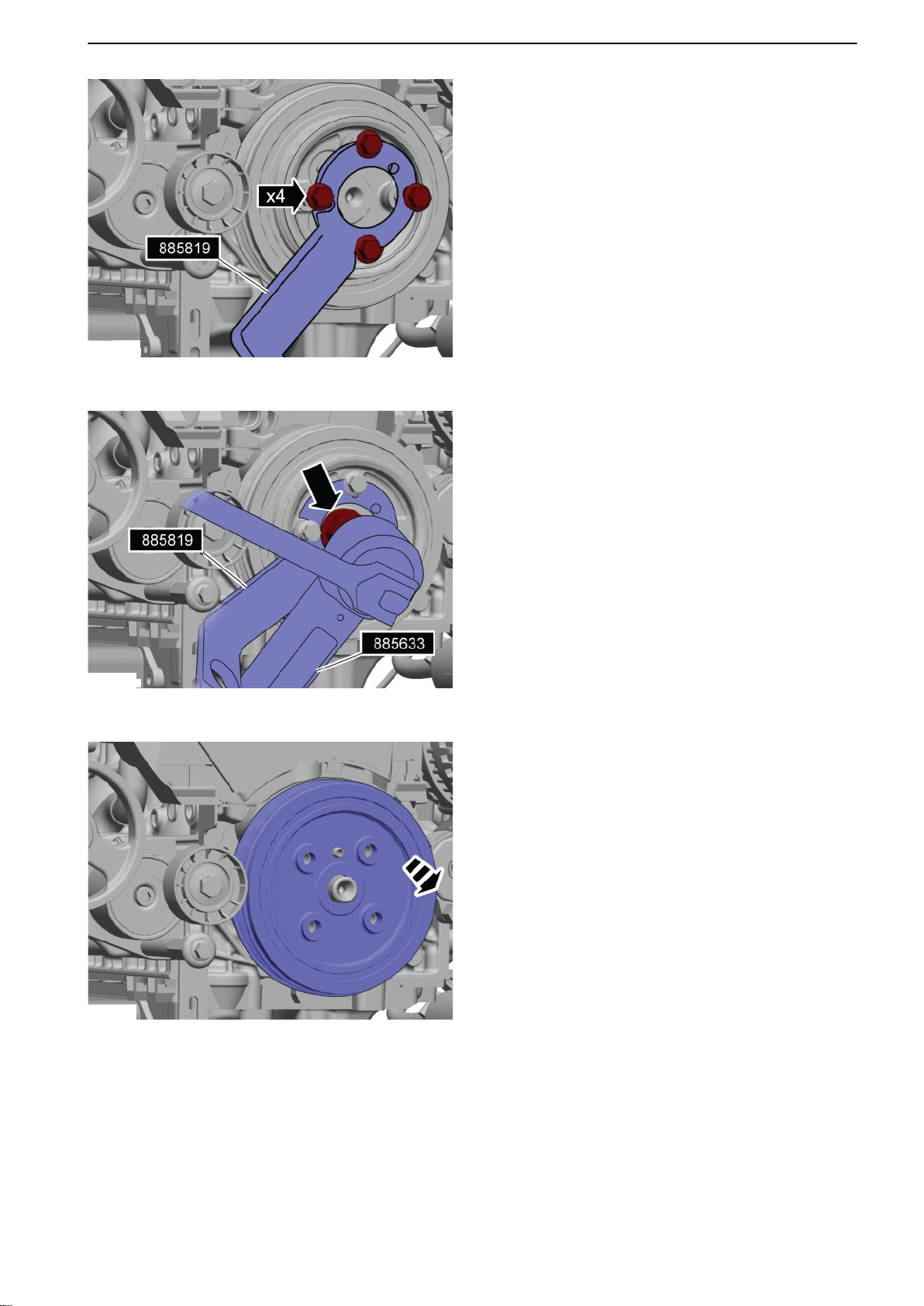
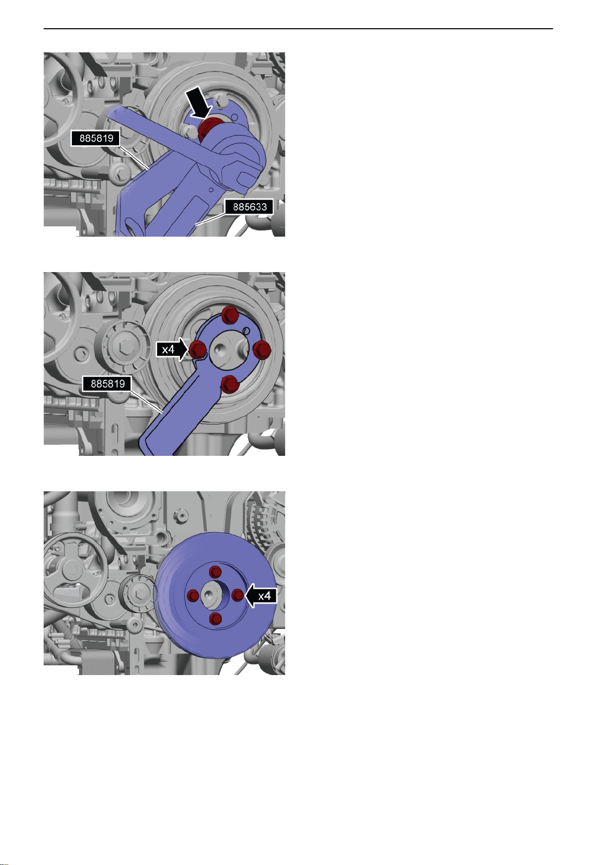
6 Install 885819 Counterhold.
7
Remove the belt pulley center bolt; use
885633 Torque multiplier.
8 Remove the belt pulley.
9 Remove the tensioner pulley.
10 Remove the camshaft belt.
47702022 12-2011 75
Page 78
P0011244
P0011245
P0011246
21-5 Timing Gears and Shaft
Installation
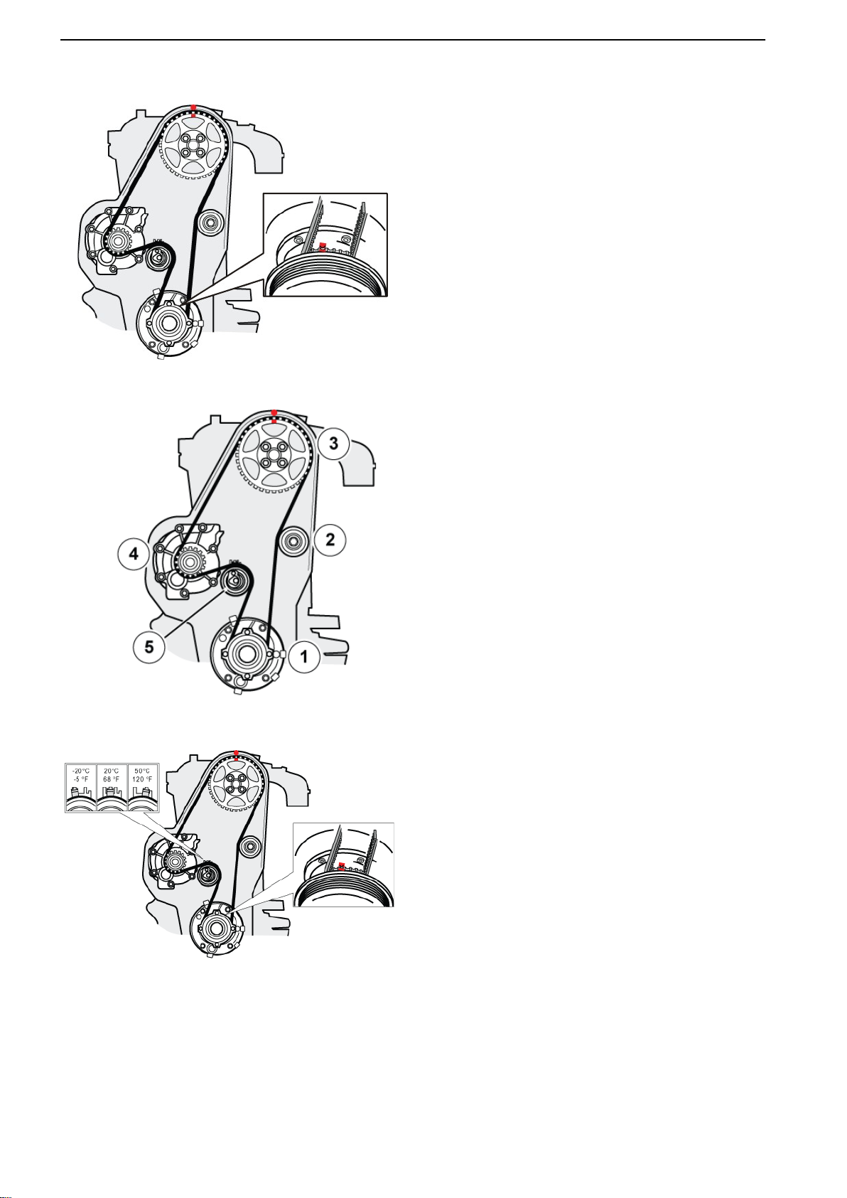
11 NOTICE!
Make sure the camshaft and upper timing gear markings are aligned according to the
“zero setting” before camshaft installation.
12 Check the idler pulley before camshaft installa-
tion.
Tightening torque: M8, 24 Nm (17.7 Ibf.ft.)
Install a new tensioner pulley; only tighten finger
tight at this time.
13 Install a new camshaft belt
1 Crankshaft
2 Idler pulley
3 Upper timing gear
4 Water pump
5 Tensioner pulley
14 Adjust belt tension.
Tighten the center bolt (M8) to: 24 Nm (17.7
Ibf.ft).
76 47702022 12-2011
Page 79
P0011251
P0011248
P0011249
21-5 Timing Gears and Shaft
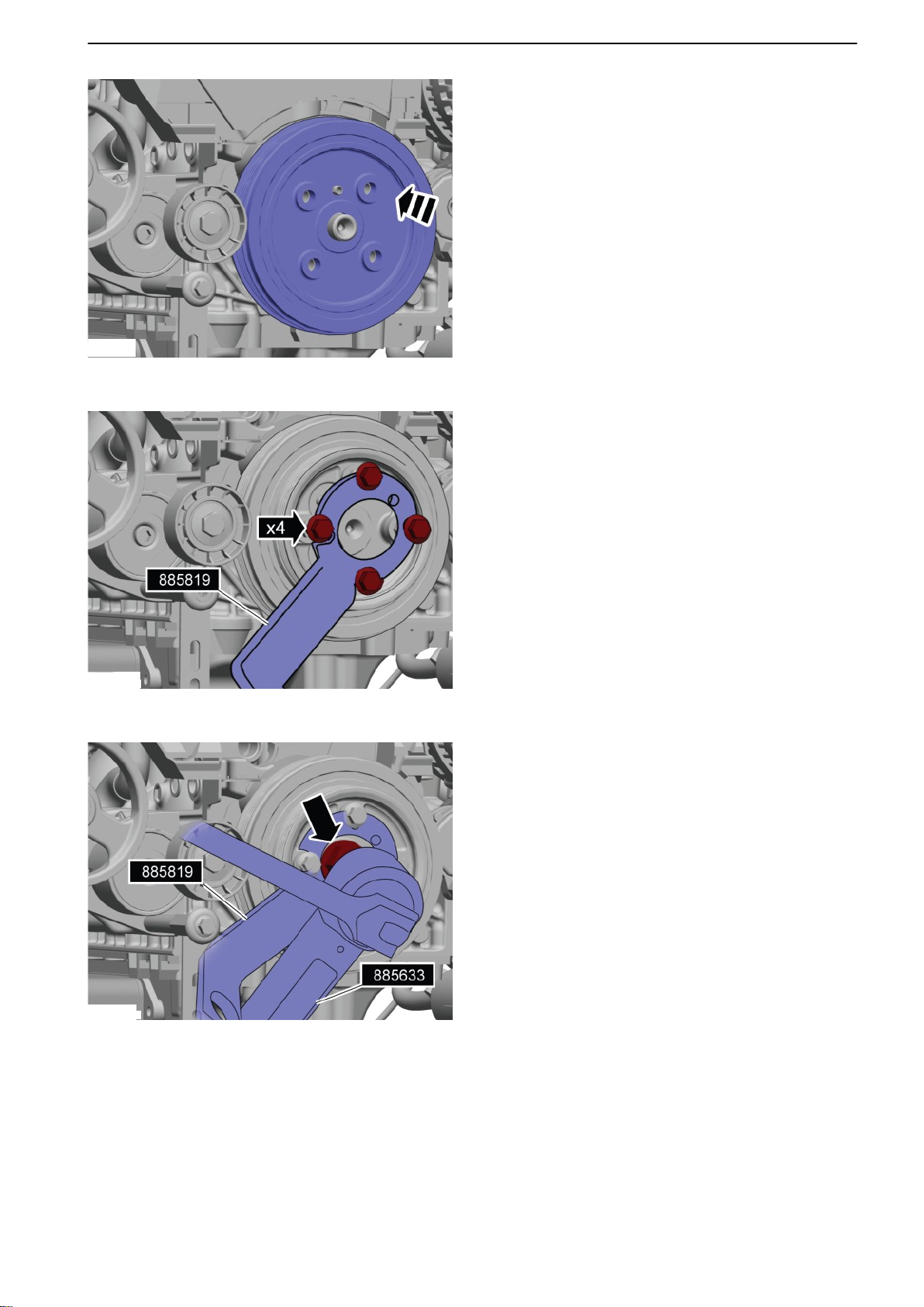
15 Install the belt pulley.
16
Install 885819 Counterhold.
17 Tighten the belt pulley.
Tightening torque: 20 Nm (14.8 Ibf.ft.)
18 Rotate the engine crankshaft (clockwise) 2 revo-
lutions, check belt tension and the markings;
adjust as necessary.
NOTICE! If adjustment is carried out, repeat the
belt tension checks.
47702022 12-2011 77
Page 80
P0011249
P0011248
P0011247
21-5 Timing Gears and Shaft
19 Tighten the belt pulley to 300 Nm (221.2 Ibf.ft);
use 885633 Torque multiplier
.
20 Remove the counterhold.
21 Install the vibration damper; tighten the bolts in
two stages:
Stage 1 35 Nm (25.8 Ibf.ft)
Stage 2 angle tighten 50°
78 47702022 12-2011
Page 81
P0011243
P0011241
21-5 Timing Gears and Shaft
22 Install the cover (M6 bolts).
23
Install the crankcase ventilation hose.
Install the engine cover (cold side) according to:
Engine Cover, replace page 68.
Install the drive belt according to: Drive Belt,
Change page 129.
47702022 12-2011 79
Page 82
21-6 Crank Mechanism
21-6 Crank Mechanism
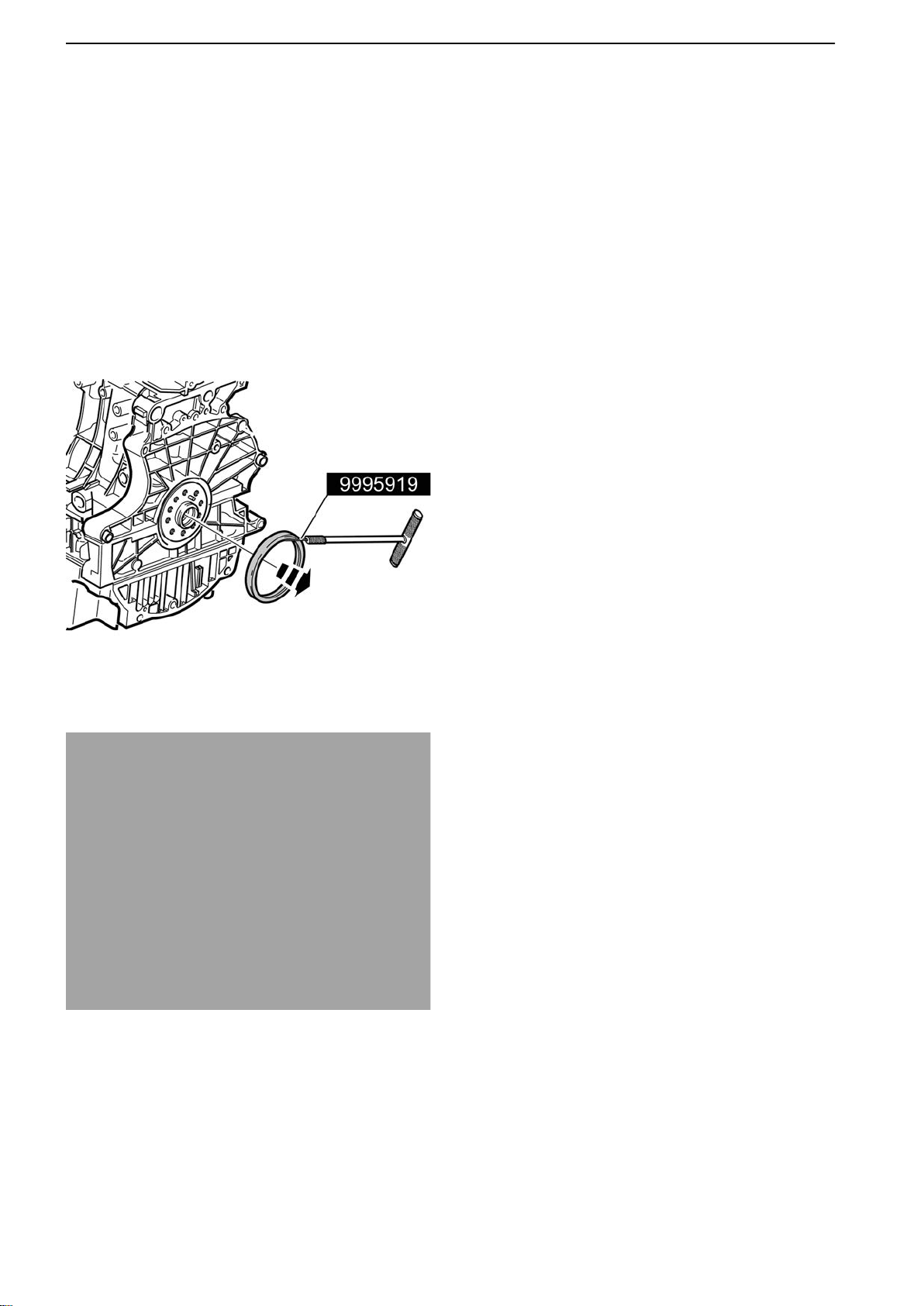
Crankshaft Seal, Change (rear)
Tools:
9995919 Extractor
9997174 Mounting tool
Removal
Remove the flywheel according to Flywheel,
Change page
1 IMPORTANT!
Take care with contact surfaces.
2 Remove the seal.
Use 9995919 Extractor.
84.
P0010738
P0010739
Installation
3 Inspect the contact surfaces before installation.
80 47702022 12-2011
Page 83
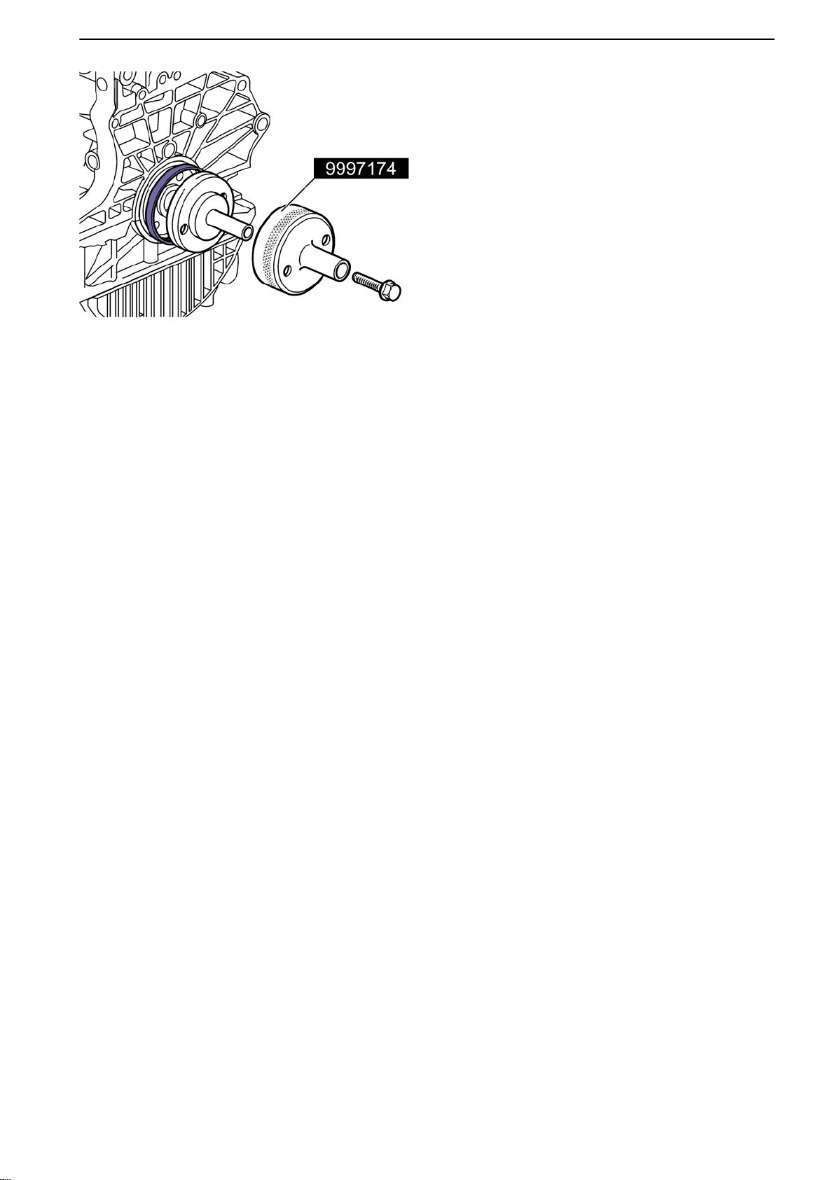
P0010740
4 Install the seal.
Use 9997174 Mounting tool
5 Install in reverse order.
21-6 Crank Mechanism
.
47702022 12-2011 81
Page 84
21-6 Crank Mechanism
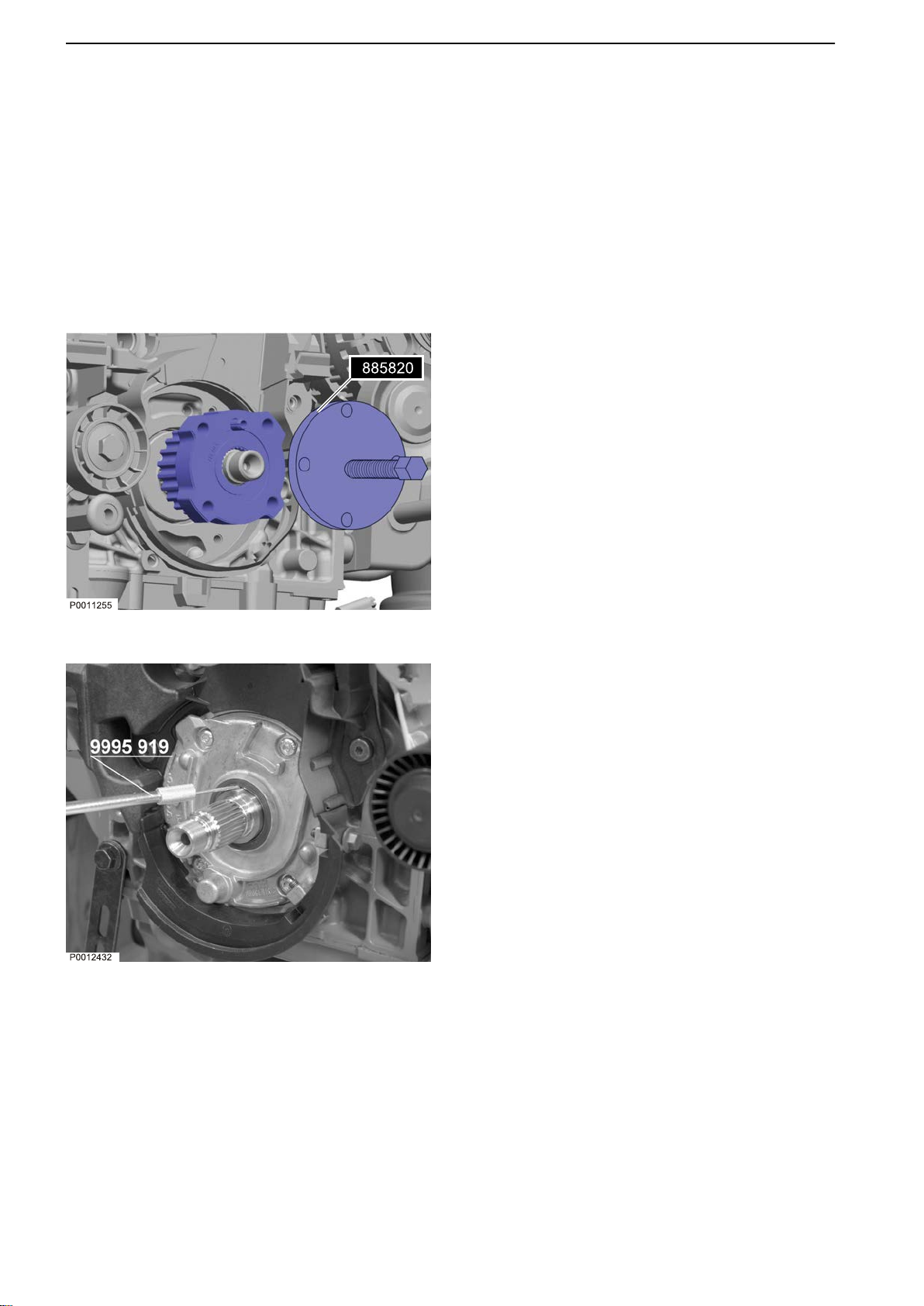
Crankshaft Seal, Change (front)
Tools:
885820 Puller
9995455 Mounting tool
9995919 Extractor
Removal
Remove the camshaft belt according to: Camshaft
Belt, Change page
1 Remove the timing gear.
Use 885820 Puller.
73.
2 Remove the crankshaft seal.
Use 9995919 Extractor.
82 47702022 12-2011
Page 85
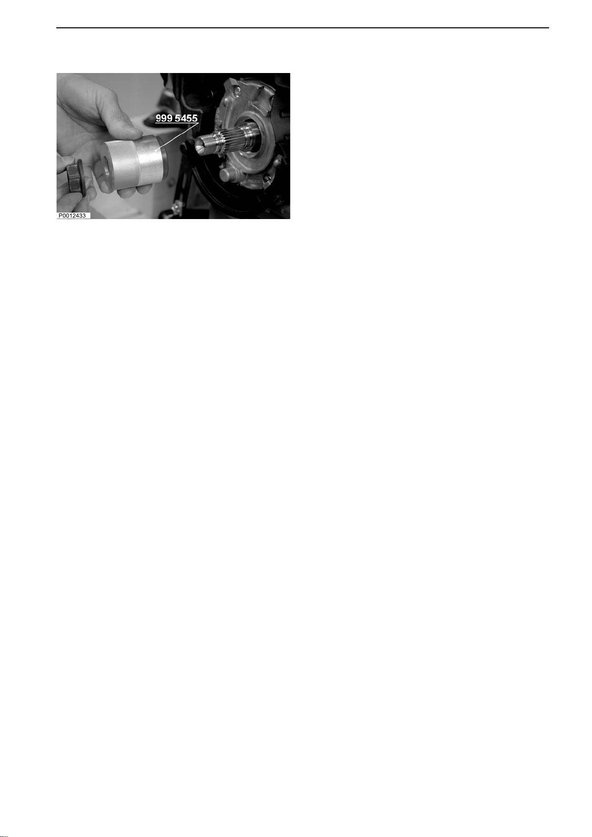
21-6 Crank Mechanism
Installation
3
Install a new seal.
Use 9995455 Mounting tool.
4 Install in reverse order.
47702022 12-2011 83
Page 86
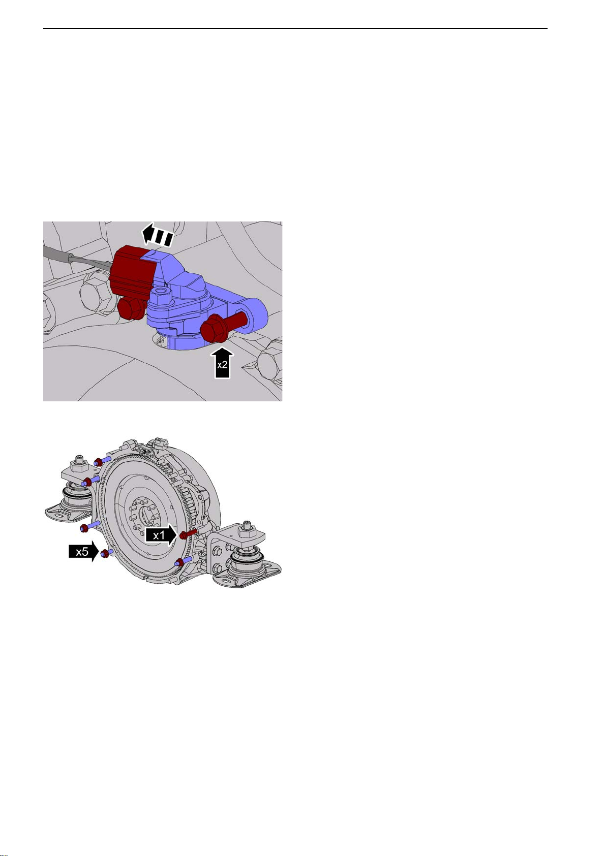
21-6 Crank Mechanism
Flywheel, Change
Tools:
21427201 Guide sleeve
Removal
Remove the reverse gear/stern drive.
Remove the heat exchanger according to Heat
exchanger, change page
Remove the starter motor according to Starter Motor,
Change page 143.
1 Undo the flywheel sensor connector.
Remove the flywheel sensor.
123.
P0010731
P0010732
2 Remove the nuts behind the flywheel as illus-
trated.
Remove the bolt located immediately beneath the
starter motor.
84 47702022 12-2011
Page 87
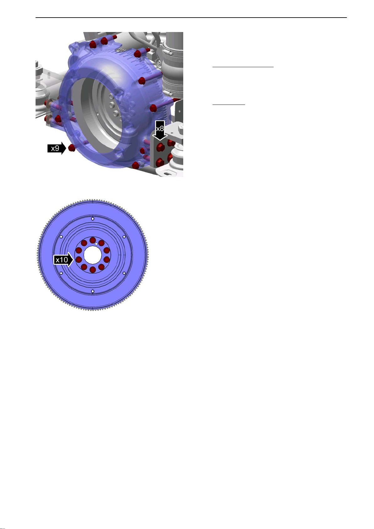
P0010733
21-6 Crank Mechanism
3 Pick out the loosened bolts.
Undo the remaining bolts.
Tightening torque: M10, 48 Nm (35.4 lbf. ft.)
Only inboard engines:
Undo the bolts on the rear engine mounting
brackets.
Tightening torque: M12, 85 Nm (62.7 lbf. ft.)
All engines:
Remove the flywheel housing.
P0010734
4
Remove the flywheel.
NOTICE! Heavy component.
Installation
5 IMPORTANT!
Inspect the contact surface before installation.
Make sure the threads are clean.
47702022 12-2011 85
Page 88
21-6 Crank Mechanism
P0010735
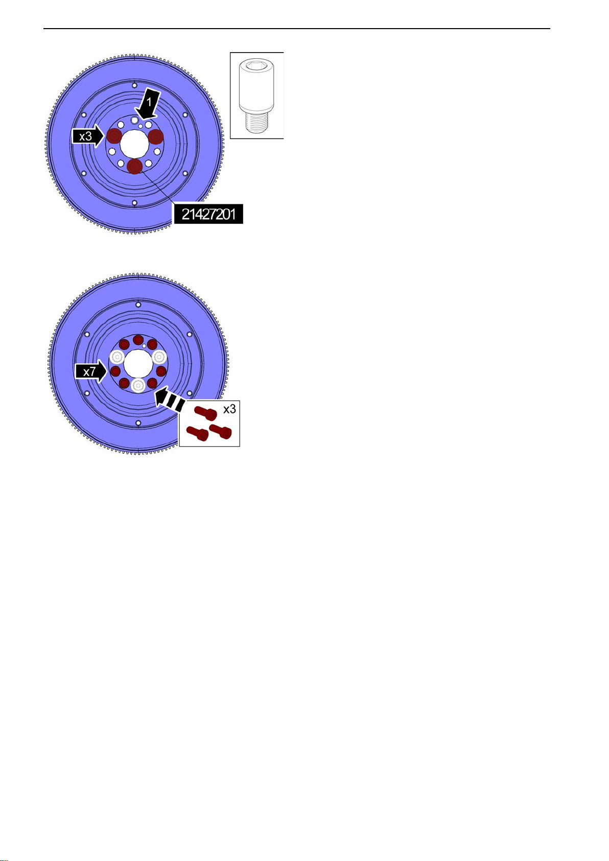
6 Fit
the flywheel, use 21427201 Guide sleeve (x3)
as illustrated.
NOTICE! The locator hole (1) must be positioned
on the crankshaft pin.
7 Install the flywheel bolts.
Remove 21427201 Guide sleeve (x3).
Install the remaining bolts.
Tightening torque
Step 1: 45 Nm (33.2 lbf.ft.)
P0010736
Step 2: 65°
8 Install in reverse order.
86 47702022 12-2011
Page 89
22-0 Lubricating and Oil System, General
22-0 Lubricating and Oil System, General
Engine Oil, Change
Removal
NOTICE! Make sure the engine is at operating tem-
perature.
NOTICE! Remove the oil filter before draining the oil.
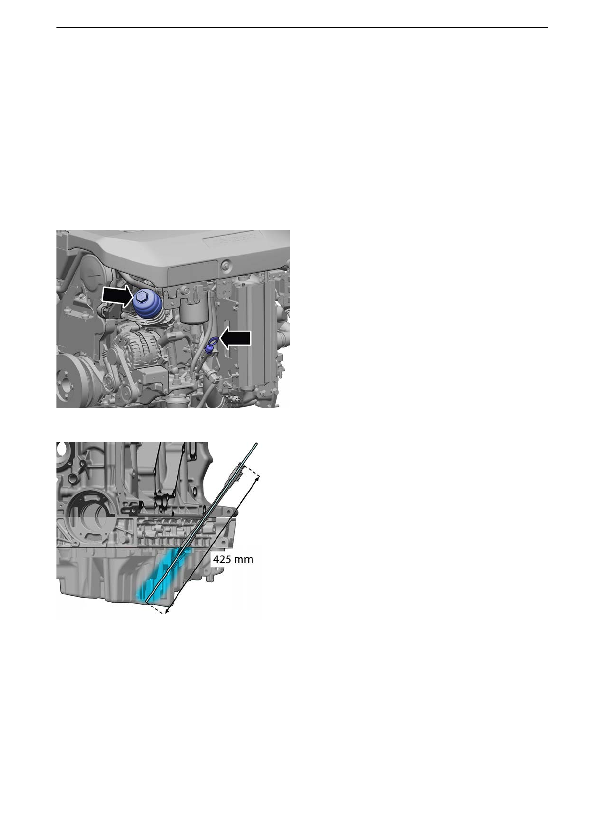
Remove the oil filter and oil dipstick.
1
Tightening torque, oil filter: 25 Nm (18.4 Ibf.ft.)
P0012267
P0012268
2 Use a pipe to drain out the oil.
Use a suitable pumping device.
NOTICE! Make sure the oil drain-off pipe is
inserted at least 425 mm (16.7").
NOTICE! Pipe diameter is 6 mm (0.24") on early
models and 10 mm (0.39") on later models.
Installation
Install in reverse order.
Finishing off
Fill with engine oil.
Run the engine until warm.
Check the oil level; top up as necessary.
47702022 12-2011 87
Page 90
P0011397
P0011398
P0011399
22-0 Lubricating and Oil System, General
Engine Oil Pressure, Check
Tools:
9995270 Pressure gauge
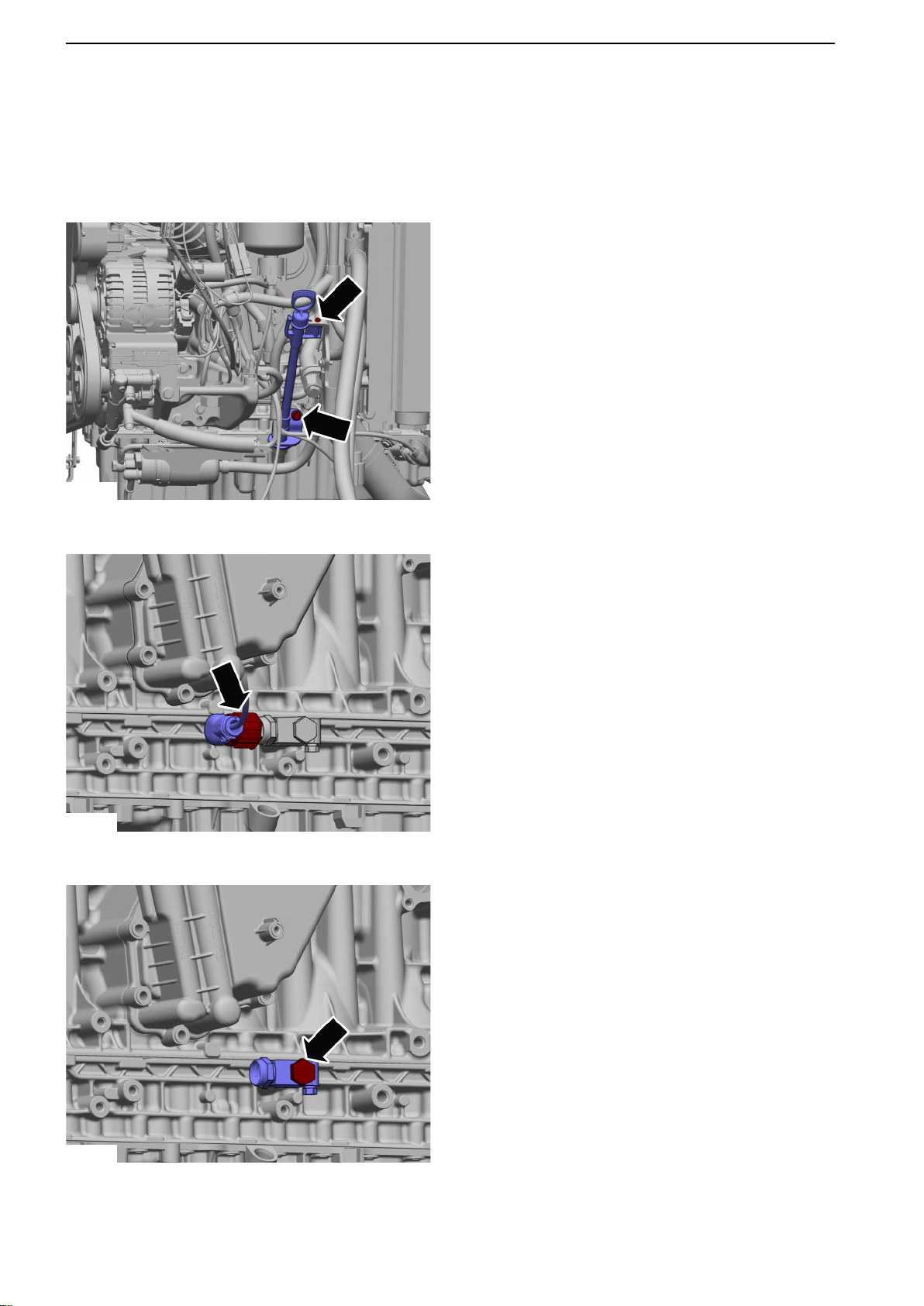
Removal
Remove the oil dipstick complete with tube.
1
2 Remove the sensor harness.
3 Remove the adapter.
4 Check the oil pressure, use 9995270 Pressure
gauge.
Refer to Technical Data page 9.
Installation
Install in reverse order.
88 47702022 12-2011
Page 91
22-1 Oil pump and Line
22-1 Oil pump and Line
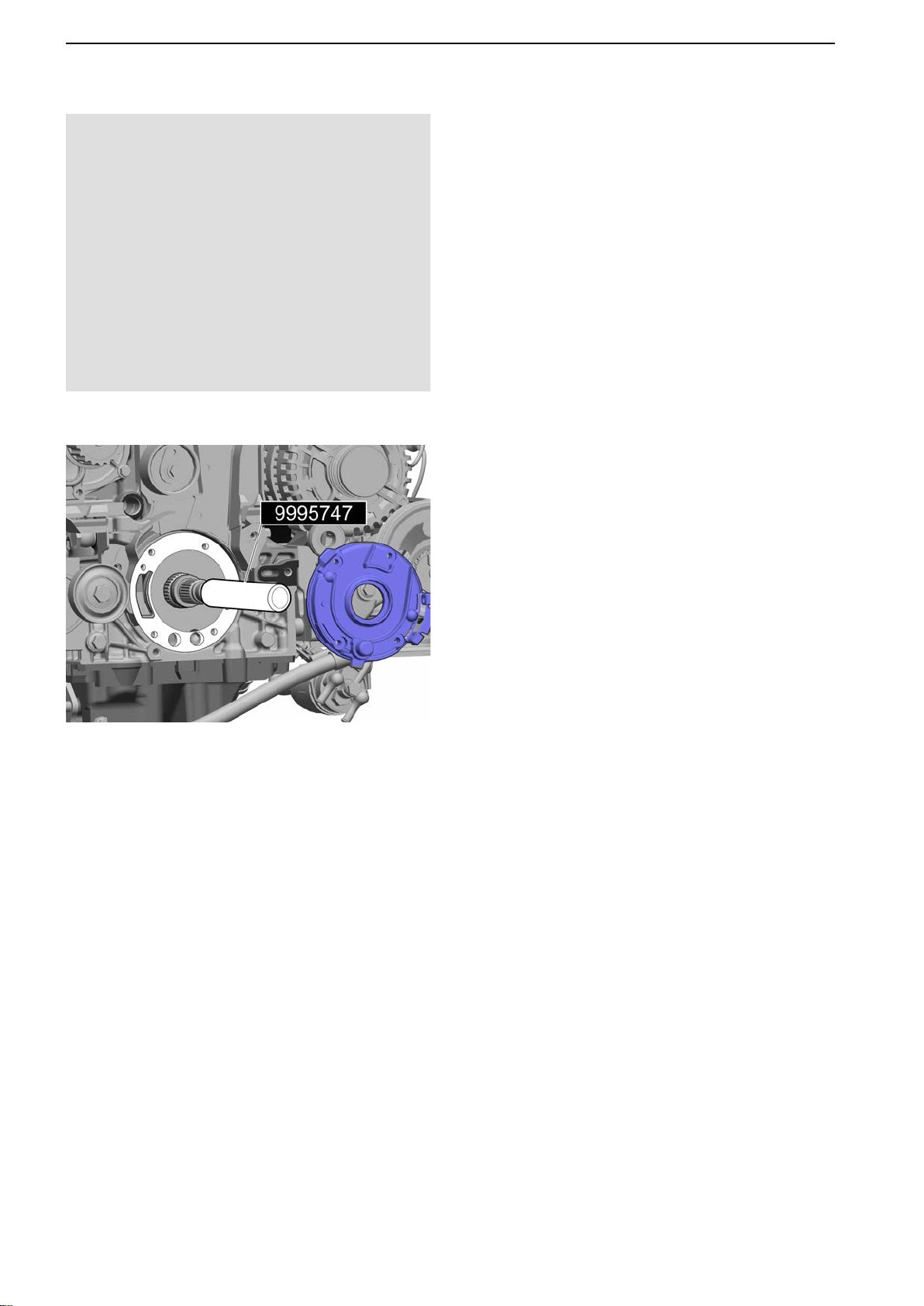
Lubrication Oil Pump, Change
Tools:
9995747 Protective sleeve
Removal
Remove the front crankshaft seal according to
1
Crankshaft Seal, Change (front) page 82.
2 Release the auxiliary alternator belt tensioner
and remove the belt according to Drive Belt,
Change page 129.
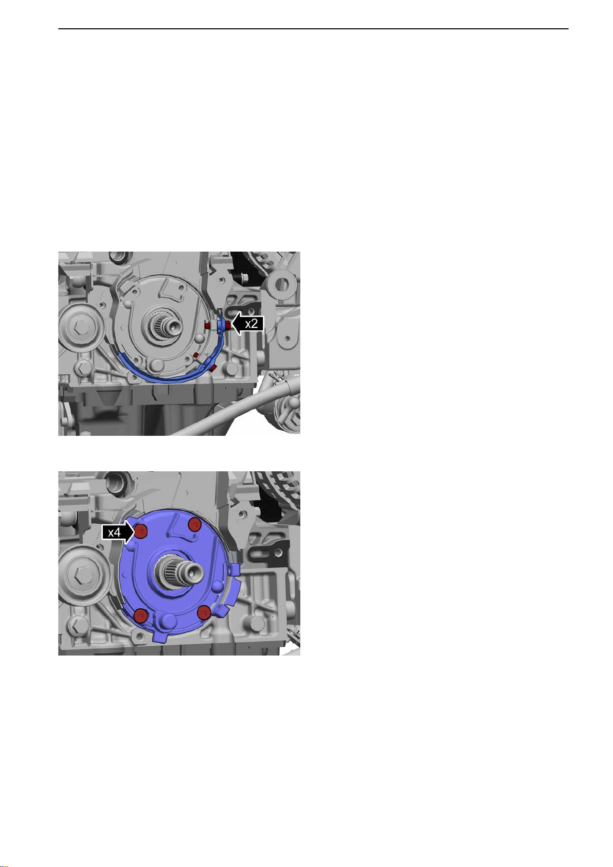
3 Remove the lower cam belt guard.
Tightening torque: M6, 10 Nm (7.4 lbf.ft.)
P0014514
P0014515
4 Remove the oil pump and gasket.
Tightening torque: M6, 10 Nm (7.4 lbf.ft.)
47702022 12-2011 89
Page 92
22-1 Oil pump and Line
P0014516
Installation
5
Install the protective sleeve, use 9995747 Protective sleeve.
6 NOTICE! Make sure the surface is clean before
application.
P0014517
Install the gasket and oil pump.
7 Install in reverse order.
90 47702022 12-2011
Page 93
22-3 Oil cooler
P0010881
P0010882
22-3 Oil cooler
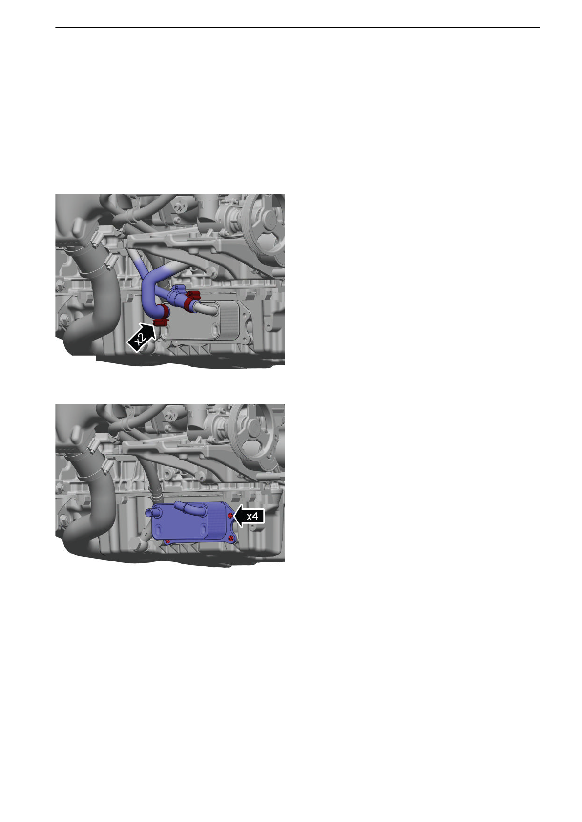
Oil Cooler, Replace
Removal
Drain the coolant according to: Coolant,
Change page
Drain the engine oil according to: Engine Oil,
Change page 87.
1 Undo the oil cooler hoses.
121.
2 Remove the oil cooler.
Installation
Install in reverse order.
47702022 12-2011 91
Page 94
P0011318
P0011319
23-3 Fuel Feed Pump and Filter
23-3 Fuel Feed Pump and Filter
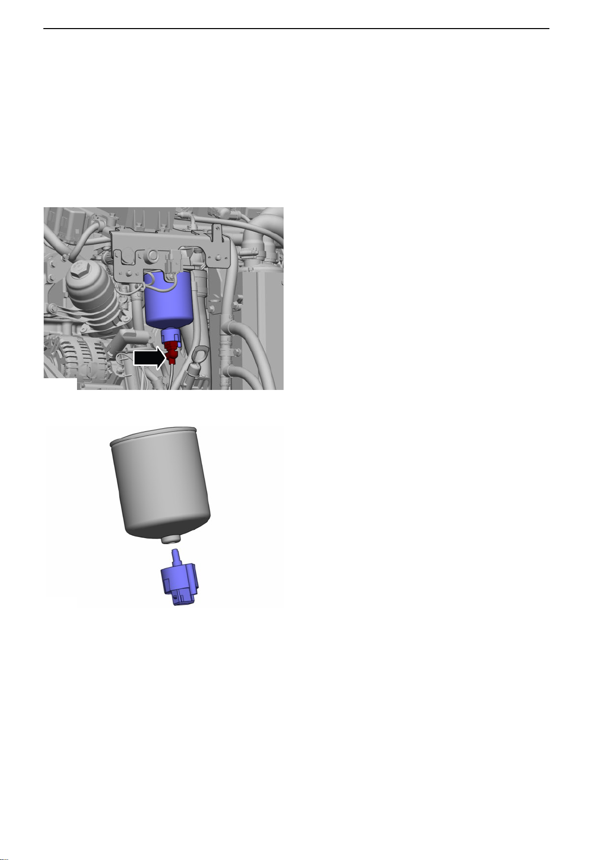
Engine Fuel Filter Replacement
Removal
NOTICE! Make sure system power is switched off.
NOTICE! Be prepared to gather up fuel.
Remove the fuel filter, incl. sensor.
1
2 Move the sensor over to the new fuel filter.
Installation
Install in reverse order.
Finishing off
Before engine start, prime the engine for around 5 sec
to bleed the system.
92 47702022 12-2011
Page 95
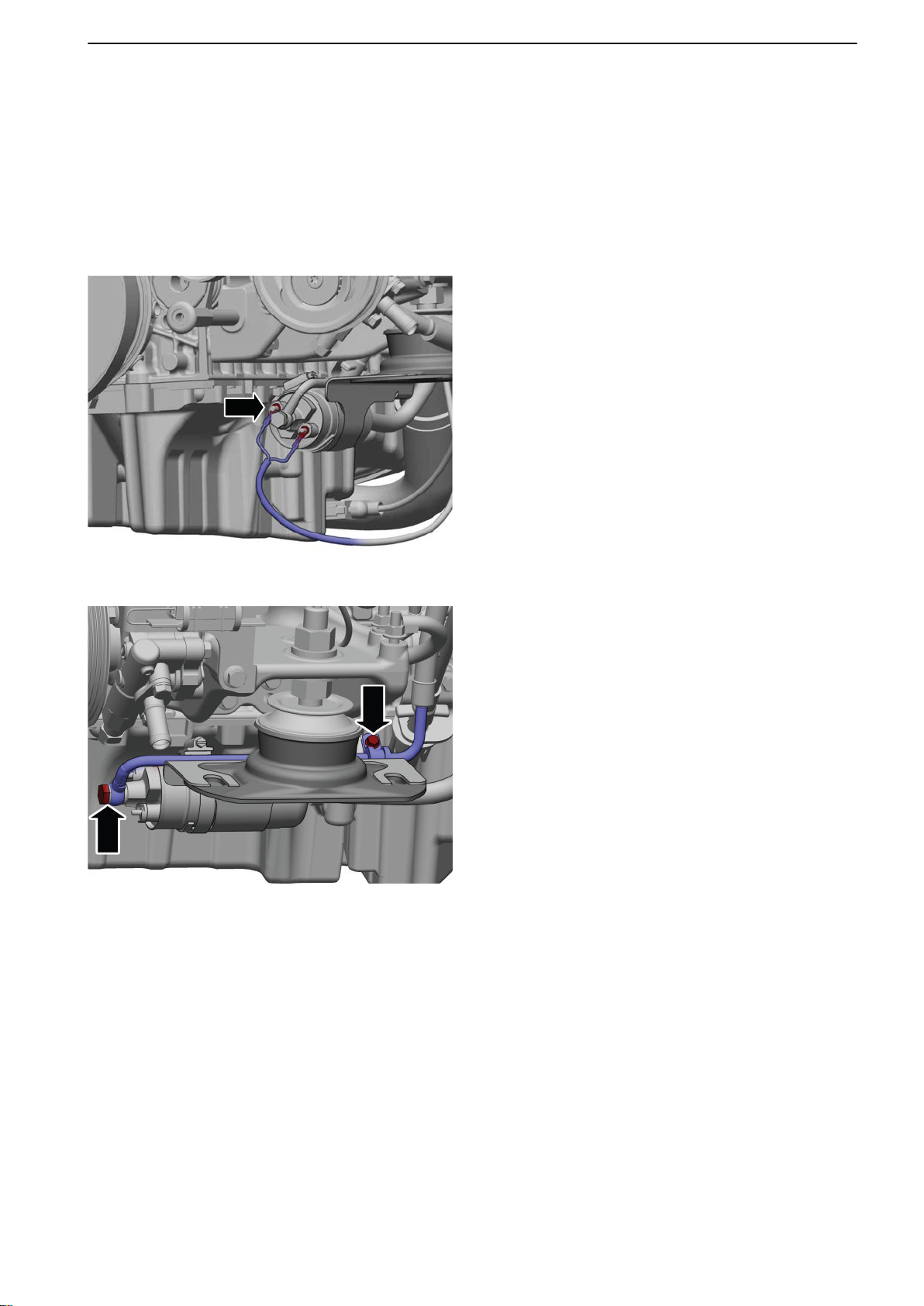
x2
P0010684
P0011252
23-3 Fuel Feed Pump and Filter
Fuel Feed Pump, Change
Removal
NOTICE! Make sure system power is switched off.
Remove the belt guard according to: Drive Belt,
Change page
1 Remove the wire harness.
129.
2 NOTICE! Be prepared to gather up fuel.
Undo the delivery pipe clamp.
Undo the delivery pipe union at the feed pump.
47702022 12-2011 93
Page 96
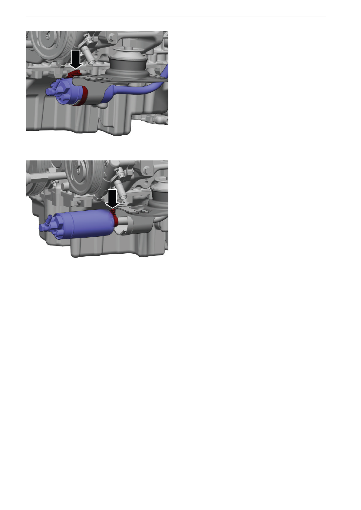
P0011253
P0011254
23-3 Fuel Feed Pump and Filter
3 Undo
the attachment, then pull the pump forward
so that the suction line is accessible.
4 Undo the suction line and then remove the feed
pump.
Installation
Install in reverse order.
94 47702022 12-2011
Page 97
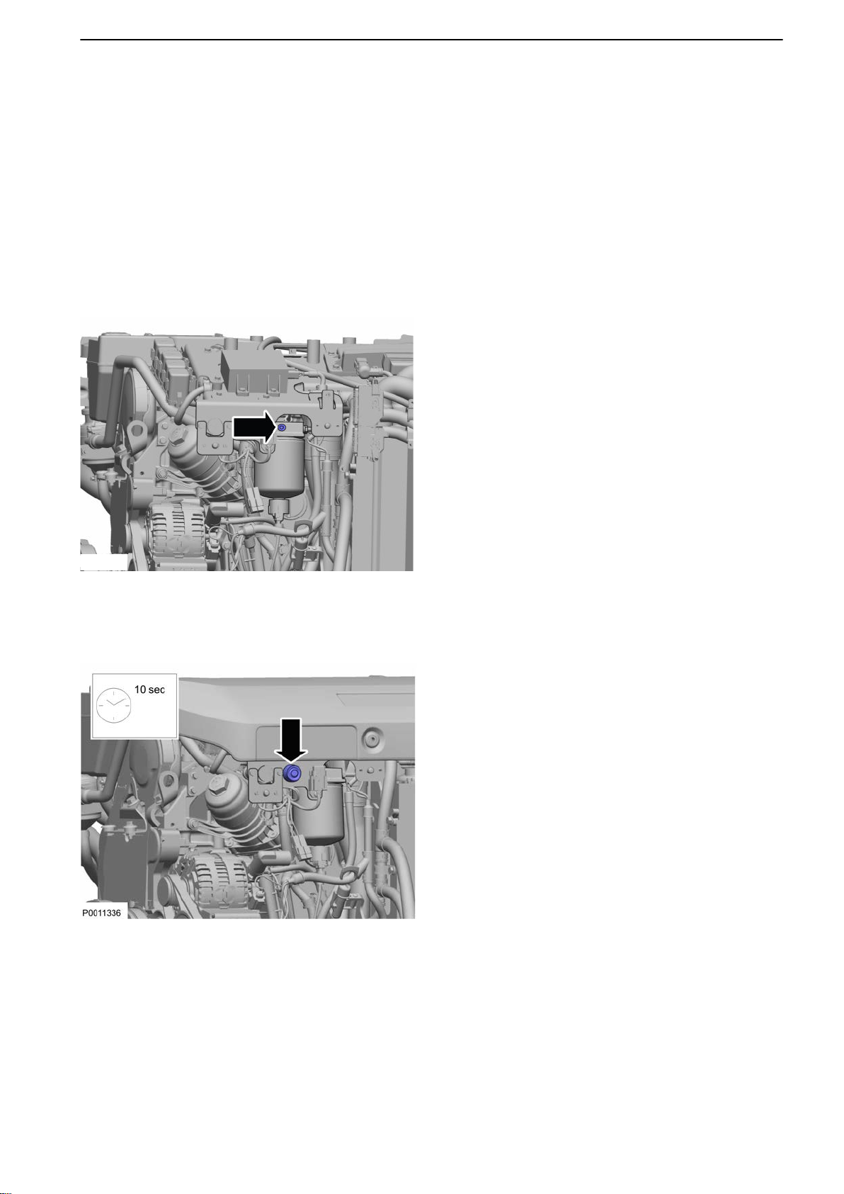
P0011335
23-3 Fuel Feed Pump and Filter
Fuel Feed Pressure, Check
Tools:
9996666 Nipple
9998493 Hose
9996398 Manometer
Removal
Remove the cold side engine cover according to:
Engine Cover, replace page
1 Remove the plug from the fuel filter housing.
68.
2 Connect 9996666 Nipple, 9998493 Hose and
9996398 Manometer.
3 NOTICE! The engine does not need to be started
to check return pressure.
Prime the engine for 10 sec.
Check the feed pressure (during the prime).
P-Normal: 3.8-4.2 bar (55-61 psi)
P-Min: 3.5 bar (51 psi)
P-Max: 5.5 Bar (80 psi)
47702022 12-2011 95
Page 98

23-3 Fuel Feed Pump and Filter
P-Min
If feed pressure is below 3.5 bar (51 psi), check
the following:
Fuel filter, according to: Engine Fuel Filter
•
Replacement page
Under pressure, according to: Fuel System
•
Vacuum, Check page 98.
P-Max
Excessive feed pressure may occur because the
inlet and return lines are transposed. The feed
pump has an integral safety valve with a pressure
range of 6-8 bar (87-116 psi), which means that
pressure cannot exceed 8 bar (116 psi).
NOTICE! In continual operations in the max position there is a risk that the pump will be damaged.
4 If the feed pressure exceeds 5.5 bar (80 psi)
check the following:
92.
Check return fuel pressure according to:
•
Fuel Return Pressure, Check page 97.
Installation
Install in reverse order.
96 47702022 12-2011
Page 99
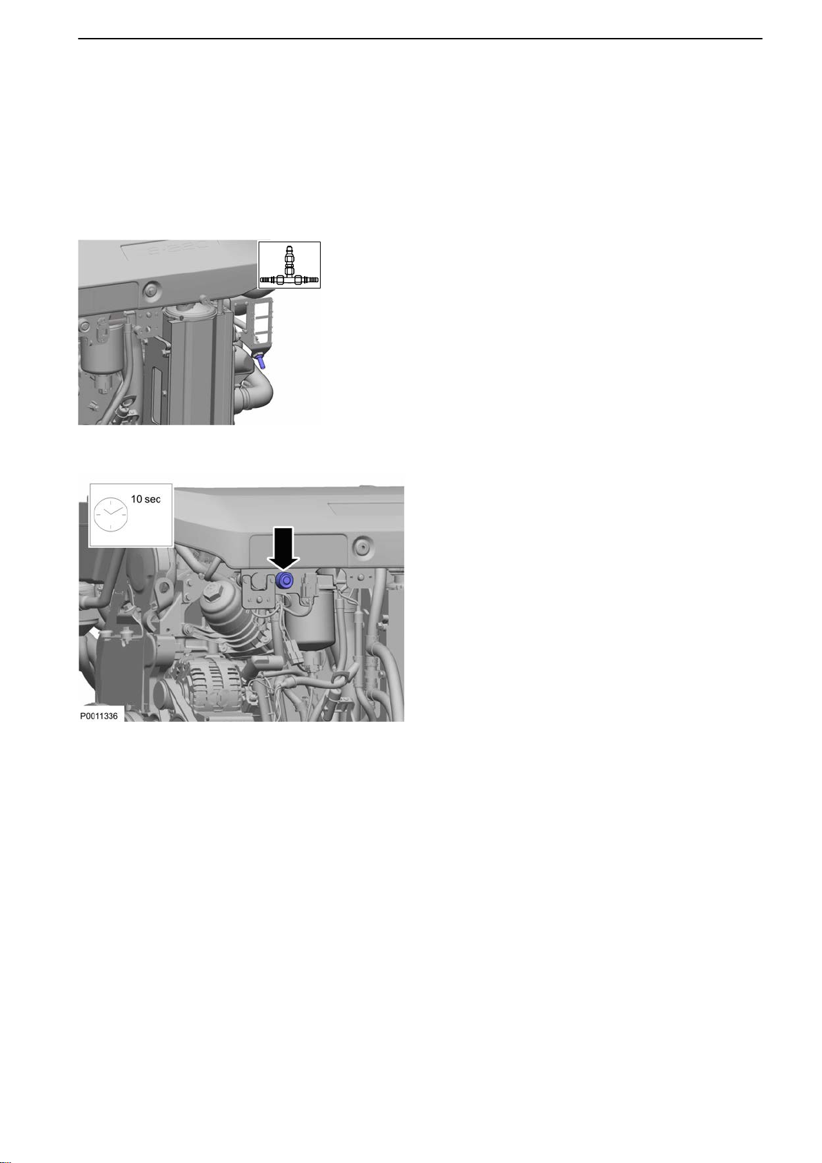
23-3 Fuel Feed Pump and Filter
Fuel Return Pressure, Check
Tools:
9996398 Manometer
9998493 Hose
21433378 Nipple
Removal
Connect 21433378 Nipple, 9998493 Hose and
1
9996398 Manometer to the output connection on
the engine.
NOTICE! A transparent hose is recommended.
P0010737
2 NOTICE! The engine does not need to be started
to check return pressure.
Prime the engine with fuel for around 10 sec.
Check the return fuel pressure while doing this.
P Norm: 0-1 bar (0-14.5 psi)
P Max: 1.0 bar (14.5 psi)
3 P Max
If the return fuel pressure exceeds 1 bar
(14.5 psi), check:
1 Return fuel lines in respect of blockages.
2 Fuel line dimensions according to specifi-
cations.
Installation
Install in reverse order.
47702022 12-2011 97
Page 100
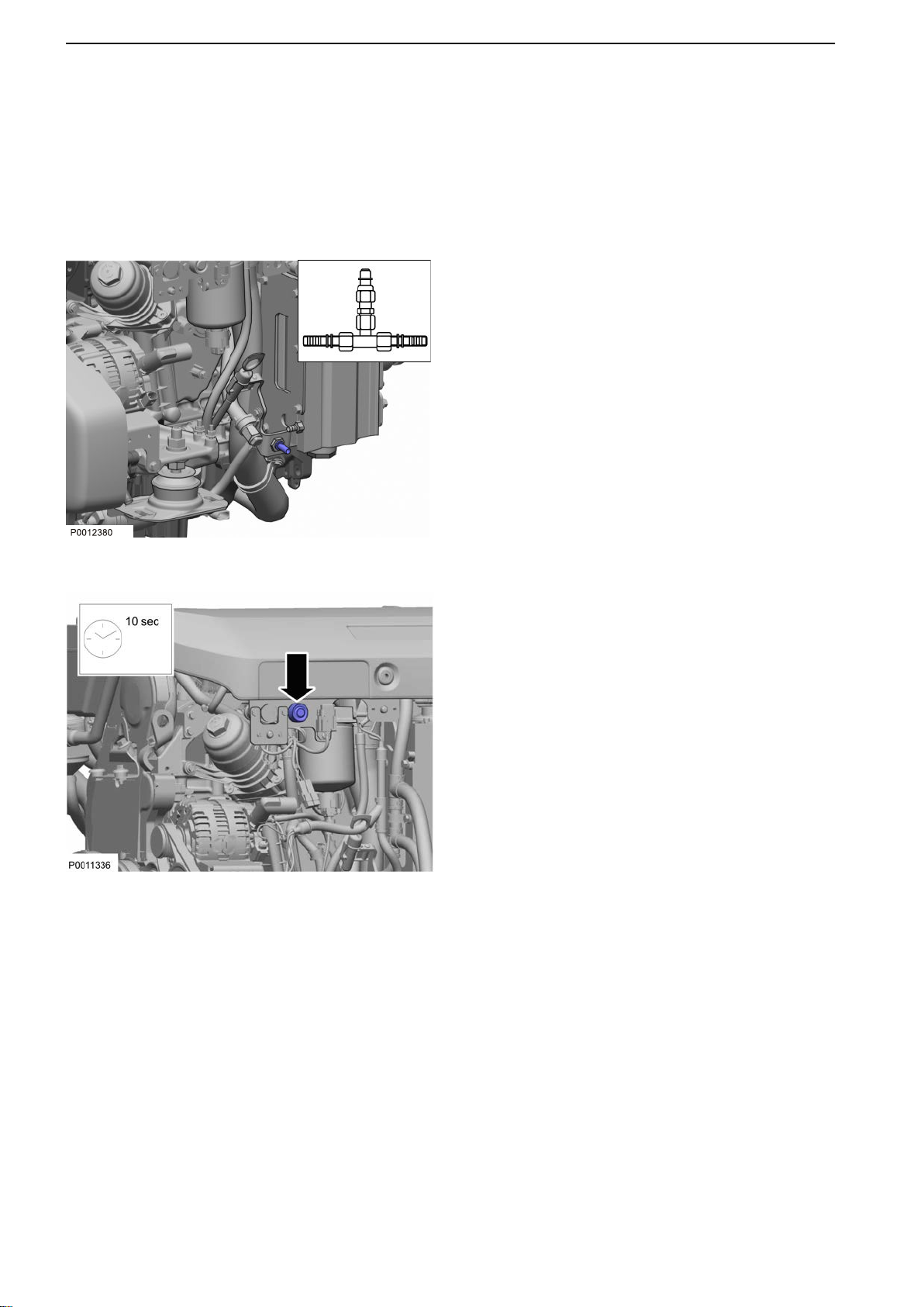
23-3 Fuel Feed Pump and Filter
Fuel System Vacuum, Check
Tools:
9990150 Manometer
9998493 Hose
21433378 Nipple
Removal
Connect 21433378 Nipple, 9998493 Hose and
1
9990150 Manometer on the suction side.
NOTICE! A transparent hose at the connection is
recommended.
2 NOTICE! The engine does not need to be started
to check vacuum.
Prime the engine for around 10 sec. Check the
vacuum while priming.
1 P Norm: 0 – (-)0.3 bar (0 – (-)43.5 psi)
2 P Min: -0.3 bar (-43.5 psi)
3 P-Min
If vacuum is below -0.3 bar (-43.5 psi), check:
1 Shut-off tap
2 Fuel prefilter
3 Fuel lines from tank
4 Fuel tank
5 The installation in regard to line dimension-
ing.
Installation
Install in reverse order.
98 47702022 12-2011
 Loading...