

Page 1

OWNER'S MANUAL
Page 2

Page 3

VÄLKOMMEN!
We trust that you will enjoy many years of safe driving in your Volvo, an
automobile designed with your safety and comfort in mind. To help get
the most from your Volvo, we urge you to familiarize yourself with the
instructions and maintenance information in this owner’s manual. The
owner’s manual can also be found in a mobile app (Volvo manual) and
on Volvo Car’s support site at support.volvocars.com.
We also urge you and your passengers to wear seat belts at all times in
this (or any other) vehicle. And, of course, please do not operate a vehi-
cle if you may be affected by alcohol, medication or any impairment that
could hinder your ability to drive.
Your Volvo is designed to meet all applicable federal safety and emission standards. If you have any questions regarding your vehicle, please
contact your Volvo retailer or see the article "Contacting Volvo" for information on getting in touch with Volvo in the United States and Canada.
Page 4

2
INTRODUCTION
Finding owner's information
14
On-board digital owner's manual
15
Navigating in the digital owner's manual
16
Owner's manual in mobile devices
18
Additional information about your vehicle
19
Using the owner's manual
20
Crash event data
22
Options, accessories and the Onboard Diagnostic (OBDII) socket
23
Volvo ID
25
Volvo and the environment
26
IntelliSafe—driver support
26
Sensus
28
Glass
31
Center display overview
32
Using the center display
34
Navigating in the center display's views
38
Symbols in the center display status bar
43
Changing center display settings
43
Function view buttons
45
Using the center display keyboard
47
Changing settings in different types
of apps
52
Volvo Structural Parts Statement
52
Driver distraction
53
Technician certification
54
Contacting Volvo
54
Volvo Roadside Assistance
55
SAFETY
General safety information
58
Safety during pregnancy
58
Whiplash protection system
59
Occupant safety
60
Reporting safety defects
61
Recall information
62
Seat belts
62
Seat belt pretensioners
63
Buckling and unbuckling seat belts
64
Door and seat belt reminders
66
Airbag system
67
Driver/passenger side airbags
67
Occupant weight sensor
70
Side impact airbags
74
Inflatable curtains
75
Safety mode
75
Starting or moving a vehicle in safety
mode
76
Child safety
77
Child restraints
79
Infant seats
80
Convertible seats
82
Booster cushions
85
ISOFIX/LATCH lower anchors
86
Lower child seat attachment points
87
TABLE OF CONTENTS
Page 5

3
Top tether anchors
88
INSTRUMENTS AND CONTROLS
Instruments and controls
90
Instrument panel
91
Instrument panel settings
93
Indicator symbols in the instrument panel
94
Warning symbols in the instrument panel
97
Ambient temperature sensor
98
Clock
99
Fuel gauge
99
Instrument panel licenses
100
Instrument panel App menu
105
Using the instrument panel App menu
106
Messages in the instrument panel
and center display
106
Handling messages in the instrument panel and center display
108
Handling messages stored from the
instrument panel and center display
110
Head-up display (HUD)*
111
Voice control
114
Using voice commands
115
Voice control settings
116
Voice control for cell phones
116
Voice control for radio and media
117
Climate system voice commands
118
Navigation system voice commands
119
Seats
119
Manually operated front seats
120
Power front seats*
120
Adjusting power front seats*
121
Using the power seat memory function*
121
Multifunctional front seats*
122
Adjusting function settings in the
multifunctional front seats*
123
Adjusting the passenger's seat from
the driver's seat*
126
Rear seats
127
Adjusting the second row head restraints
127
Moving the front passenger's seat
from the rear seat
128
Folding down the rear seat backrests
129
Steering wheel
130
Adjusting the steering wheel
131
Lighting panel and controls
132
Parking lights
134
Low beam headlights
134
High and low beam headlights
135
Daytime Running Lights (DRL)
137
Active Bending Lights*
137
Front fog lights*
138
Rear fog light
139
Page 6

4
Brake lights
140
Hazard warning flashers
140
Using turn signals
140
Passenger compartment lighting
141
Home safe lighting
143
Approach lighting
144
Using the windshield wipers
144
Activating/deactivating the rain sensor
145
Windshield and headlight washers
146
Power windows
147
Operating the power windows
147
Using sun curtains*
149
Adjusting the power door mirrors
151
Rearview mirror
152
Compass
153
Calibrating the compass
154
Laminated panoramic roof
155
Operating the laminated panoramic roof
156
HomeLink® Wireless Control System*
160
Programming the HomeLink® Wireless Control System*
161
Trip computer
164
Displaying trip computer information
165
Displaying trip statistics
166
Settings view
167
Categories in Settings view
168
Changing system settings in Settings view
169
Resetting the settings view
170
Driver profiles
171
Selecting a driver profile
171
Editing a driver profile
172
Linking a remote key to a driver profile
173
Importing/exporting a driver profile
from/to a USB flash drive
174
Changing settings in apps
175
Resetting user data when the vehicle
changes owners
175
CLIMATE
Climate control system
178
Climate system sensors
179
Perceived temperature
179
Air quality
180
Passenger compartment air filter
181
Clean Zone Interior Package (CZIP)*
181
Interior Air Quality System (IAQS)*
181
Climate system controls
182
Climate system controls in the center
display
183
Rear climate system controls on the
tunnel console*
184
Automatic climate control
185
Air conditioning
186
Setting the temperature
186
Setting the blower speed
189
Defrosting windows and mirrors
190
Turning recirculation on and off
192
Air distribution
193
Adjusting air distribution
194
Opening/closing/directing air vents
194
Air distribution table
196
Turning seat heating* on and off
198
Turning front seat ventilation* on and off
200
Page 7

5
Turning steering wheel heating* on
and off
201
LOADING AND STORAGE
Passenger compartment storage spaces
204
Tunnel console
205
Electrical sockets
206
Using the glove compartment
207
Sun visors
208
Loading
208
Load anchoring eyelets
210
Grocery bag holder
211
Ski hatch*
211
LOCKS AND ALARM
Locks and remote keys
214
Remote key
214
Remote key's range
216
Red Key*
217
Antenna locations for the start and
lock system
218
Locking/unlocking from outside the
vehicle
219
Locking and unlocking confirmation
221
Locking/unlocking from inside the
vehicle
222
Locking/unlocking the trunk
223
Private (valet) locking
226
Detachable key blade
227
Locking/unlocking with the detachable key blade
228
Power trunk release*
229
Foot movement trunk operation*
231
Changing the remote key's battery
232
Immobilizer
235
Child safety locks
236
Alarm
237
Automatically arming/disarming the
alarm
238
Deactivating the alarm without a
functioning remote key
239
Page 8

6
Start and lock system type designations
239
DRIVER SUPPORT
Driver support systems
242
Adjustable steering force*
242
Roll stability control (RSC)
243
Electronic Stability Control (ESC)
243
Electronic Stability Control (ESC)
sport mode
244
Electronic Stability Control (ESC)
symbols and messages
245
Speed limiter (SL)*
247
Starting and activating the Speed
Limiter (SL)*
248
Changing a Speed Limiter (SL)*
maximum speed
248
Deactivating/reactivating the Speed
Limiter*
249
Turning the Speed Limiter* off
250
Automatic Speed Limiter (ASL)*
250
Activating/deactivating the
Automatic Speed Limiter (ASL)*
252
Changing tolerance for the
Automatic Speed Limiter
252
Cruise Control (CC)
253
Starting and activating Cruise Control
254
Changing Cruise Control (CC) speed
255
Deactivating/resuming Cruise
Control (CC)
256
Turning Cruise Control off
257
Distance Alert*
258
Using Distance Alert*
259
Distance Alert* limitations
260
Adaptive Cruise Control (ACC)*
260
Starting and activating Adaptive
Cruise Control (ACC)*
263
Changing Adaptive Cruise Control
(ACC) speed
264
Setting an Adaptive Cruise Control
(ACC) time interval
265
Deactivating/resuming Adaptive
Cruise Control (ACC)
266
Passing Assistance with Adaptive
Cruise Control (ACC)* or Pilot Assist*
268
Changing target vehicles and automatic braking with Adaptive Cruise
Control (ACC)
269
Adaptive Cruise Control (ACC) - limitations
270
Switching between Cruise Control
(CC) and Adaptive Cruise Control (ACC)*
271
Adaptive Cruise Control (ACC) symbols and messages
272
Pilot Assist*
274
Starting and activating Pilot Assist
277
Changing Pilot Assist speed
279
Setting a Pilot Assist time interval
280
Deactivating/resuming Pilot Assist
282
Page 9

7
Changing target vehicles and automatic braking with Pilot Assist
284
Pilot Assist limitations
285
Pilot Assist symbols and messages
287
Driver support system radar sensor
288
Radar sensor limitations
290
Radar sensor - type approval
293
Driver support system camera
293
Camera limitations
294
City Safety™
297
City Safety warning level settings
299
Detecting obstructions with City Safety
301
City Safety in crossing traffic
303
City Safety when evasive action is
not possible
304
City Safety limitations
304
City Safety symbols and messages
307
Rear Collision Warning (RCW)
308
Blind Spot Information (BLIS)*
309
Blind Spot Information (BLIS)* On/Off
310
Blind Spot Information (BLIS)* limitations
311
Cross Traffic Alert (CTA)*
311
Activating/deactivating Cross Traffic
Alert (CTA)*
312
Cross Traffic Alert (CTA)* limitations
313
Blind Spot Information (BLIS)* with
Cross Traffic Alert (CTA)* symbols
and messages
315
Road Sign Information (RSI)*
316
Road Sign Information (RSI)* operation
317
Road Sign Information (RSI)* limitations
318
Driver Alert Control (DAC)
319
Using Driver Alert Control (DAC)
320
Driver Alert Control limitations
320
Driving lane assistance
320
Activating/deactivating Lane
Keeping Aid (LKA)
322
Driving lane assistance symbols and
messages
324
Steering assistance when there is a
risk of a collision
326
Steering assistance symbols and
messages
327
Steering assist with run-off mitigation
328
Steering assistance in oncoming traffic
329
Steering assistance during collision
risks from behind
331
Park Assist*
332
Activating/deactivating Park Assist
334
Park Assist limitations
334
Park Assist symbols and messages
336
Park Assist Camera (PAC)*
337
Park Assist Camera (PAC)* trajectory
lines and fields
339
Starting the Park Assist Camera (PAC)*
341
Park Assist Camera (PAC)* limitations
342
Park Assist Camera (PAC)* - symbols and messages
344
Park Assist Pilot (PAP)*
346
Using Park Assist Pilot (PAP)*
347
Park Assist Pilot (PAP)* limitations
350
Park Assist Pilot (PAP)* symbols and
messages
352
Page 10

8
STARTING AND DRIVING
Starting and driving
354
Ignition modes
354
Starting the engine
355
Turning the engine off
357
Jump starting
358
Automatic transmission
359
Gear selector positions
360
Gear shift indicator
361
Shiftlock
362
Steering wheel paddles*
363
Start/Stop
364
Using the Start/Stop function
364
Conditions for Start/Stop
366
Drive modes*
367
ECO drive mode
370
Leveling control* and suspension
372
Brake functions
373
Brakes
373
Emergency brake lights
375
Brake assist system
375
Braking effect after a collision
376
Parking brake
376
Using the parking brake
377
Parking brake malfunctions
378
Hill Start Assist
379
Auto-hold brake function
379
Driving through standing water
380
Overheating the engine and transmission
381
Battery drain
382
Before a long distance trip
382
Winter driving
383
Opening/closing the fuel filler door
383
Fuel
384
Octane rating
385
Emission controls
386
Driving economically
387
Driving with a trailer
388
Trailer Stability Assist (TSA)
390
Towing eyelet
391
Towing recommendations
393
INFOTAINMENT
The infotainment system
396
Apps (applications)
396
Sound settings
397
Radio
398
Changing and searching for radio
stations
398
RBDS radio
400
HD Radio™reception
400
Switching HD Radio on and off
401
HD Radio sub-channels
402
HD Radio limitations
403
SiriusXM® Satellite radio*
403
Using SiriusXM® Satellite radio*
404
SiriusXM® Satellite radio* settings
406
SiriusXM Travel Link*
407
SiriusXM Travel Link - Weather
408
SiriusXM Travel Link - Alerts
409
SiriusXM Travel Link - Fuel
410
SiriusXM Travel Link - Sports
411
Radio settings
412
Media player
413
Playing media
413
Gracenote
416
Media searches
416
Page 11

9
CD (media) player*
417
Streaming media through a Bluetooth connection
417
Connecting a Bluetooth® device
418
Playing media through the USB socket
418
Connecting a device via the USB socket
418
Video
419
Media sound settings
419
Apple CarPlay
420
Apple CarPlay settings
422
Android auto*
422
Android Auto* settings
424
Media player technical data
424
Phone
426
Pairing a cell phone
427
Connecting/disconnecting a cell phone
428
Handling phone calls
429
Handling text messages
430
Managing the phone book
431
Phone settings
432
Text message settings
432
Bluetooth settings
432
Internet connected vehicle
433
Connecting to the Internet
434
Tethering (Wi-Fi sharing)
435
Internet connection troubleshooting
436
Deleting Wi-Fi networks
436
Wi-Fi technology and security
437
Vehicle modem settings
437
Downloading, updating and uninstalling apps
438
Infotainment system license information
439
Terms, conditions and confidentiality
443
WHEELS AND TIRES
Tires
446
Tire direction of rotation
448
Tread wear indicator
448
Checking tire inflation pressure
449
Tire Pressure Monitoring System (TPMS)
450
Checking tire inflation pressure
452
Reinflating tires equipped with the
Tire Pressure Monitoring System (TPMS)
453
Calibrating the Tire Pressure
Monitoring System (TPMS)
454
Tire sealing system
455
Using the tire sealing system
457
Inflating a tire with the tire sealing
system compressor
461
Changing tires
462
Removing a wheel
463
Installing a wheel
464
Wheel bolts
465
Snow tires and chains
465
Tools
466
Jack
466
Wheel (rim) designations
467
Tire sidewall designations
467
Tire terminology
469
Loading specifications
470
Page 12

10
Uniform Tire Quality Grading
471
MAINTENANCE AND SERVICING
Volvo's service program
474
Vehicle status
476
Booking service and repairs
476
Remote updates
479
System updates
479
Hoisting the vehicle
481
Opening and closing the hood
483
Engine compartment overview
484
Engine oil
485
Checking and refilling engine oil
486
Refilling coolant
487
Climate system service
488
Replacing bulbs
488
Replacing low beam headlight bulbs
490
Replacing High Beam headlight bulbs
491
Replacing front parking light bulbs
492
Replacing front turn signal bulbs
492
Replacing the rear fog light
493
Bulb specifications
495
Windshield wipers in the service position
496
Replacing wiper blades
497
Refilling the windshield washer fluid
reservoir
498
Start battery
499
Battery symbols
501
Support battery
502
Fuses
503
Replacing fuses
504
Fuses in the engine compartment
505
Fuses in the passenger compartment
509
Fuses in the trunk
513
Cleaning the exterior
516
Polishing and waxing
518
Corrosion protection
519
Cleaning the interior
519
Cleaning the center display
521
Paint damage
522
Touching up paint damage
523
Page 13

11
SPECIFICATIONS
Label information
526
Dimensions
529
Weights
531
Engine specifications
533
Engine oil specifications and volume
535
Coolant specifications
535
Transmission fluid specification and
volume
536
Brake fluid specification and volume
536
Fuel tank volume
536
Air conditioning refrigerant
537
Tire inflation pressure table
538
INDEX
Index 539
Page 14

Page 15

INTRODUCTION
Page 16
INTRODUCTION
14
Finding owner's information
Owner's information is available in several different formats in both digital and printed form. The
owner's manual is available on the vehicle's center display, as a mobile app and on Volvo's support website.
There is also a Quick Guide in the glove compartment as well as a printed supplement to the
owner's manual containing information about
e.g., fuses, specifications, etc. A complete printed owner's manual can also be ordered.
The vehicle's center display
In the center display, pull down
Top view and tap
Owner's
manual. This gives you access
to visual navigation with exterior
and interior images of the vehicle. The information is searchable and is divided into catego-
ries.
Mobile app
In App Store or Google Play,
search for "Volvo Manual."
Download the app to a smartphone or tablet and select a
vehicle model. The app contains instructive videos and
offers visual navigation, including interior and exterior images of the vehicle.
Navigation between the various articles in the
owner's manual is designed to provide easy
access to the information and the information is
searchable.
Volvo Cars' support site
Go to support.volvocars.com
and select your country.
Owner's manuals are available
here online and in PDF format.
Volvo Cars' support site also
contains instructional videos
and additional information
about your vehicle and owning a Volvo.
Printed owner's information
The glove compartment contains a printed supplement to
the owner’s manual containing
information about fuses and
specifications as well as a summary of other important and
practical information.
A printed Quick Guide can also be found in the
glove compartment containing useful information
about the most commonly used features and
functions in your vehicle.
Other printed owner's information may also be
found in the vehicle, depending on options
and/or accessories that the vehicle is equipped
with.
A complete printed version of the owner's information (or a new owner's manual supplement)
can be ordered through a Volvo retailer.
NOTE
If the content of the digital information in the
center display and the printed information differ, the printed information always has precedence.
Page 17
INTRODUCTION
}}
15
WARNING
The driver is always responsible for operating
the vehicle in a safe manner and adhering to
current laws and traffic regulations.
It is also important that the vehicle be operated, maintained and serviced according to
Volvo's recommendations/instructions in the
owner's manual.
Changing the language used in the vehicle's center display
Changing languages in the center display could
mean that some of the owner's information provided may not comply with national or local statutes and regulations. Changing to a language
that you do not understand may also make it difficult to change back to the original language.
Related information
•
Owner's manual in mobile devices (p. 18)
•
Navigating in the digital owner's manual
(p. 16)
•
On-board digital owner's manual (p. 15)
•
Navigating in the digital owner's manual
(p. 16)
•
Using the owner's manual (p. 20)
•
Additional information about your vehicle
(p. 19)
On-board digital owner's manual
When printed owner's information refers to digital owner's information, this is the on-board information available in the vehicle's center display.
The digital on-board owner's manual is accessed from
the center display's Top view
There are a number of ways to find information in
the digital owner's manual, which can be
accessed from the manual's top menu by tapping
.
NOTE
The on-board owner's information cannot be
accessed while the vehicle is moving.
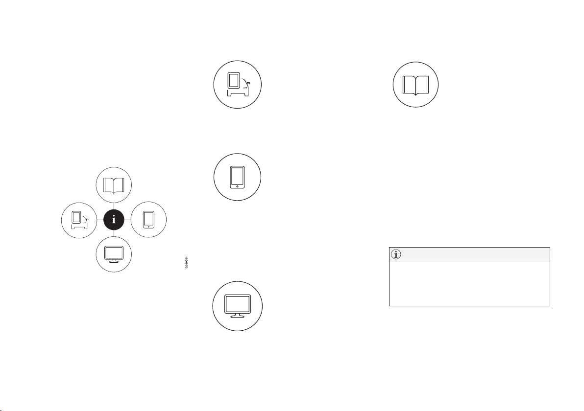
Symbols and their descriptions
Takes you to the owner's
information start page.
All articles sorted by category. An article may be listed in several categories.
A selection of useful articles about the most commonly used functions in the
vehicle.
Page 18
||
INTRODUCTION
16
Symbols and their descriptions
Exterior/interior views of
the vehicle in which certain
areas/components are
highlighted as hotspots.
Tap a hotspot to come to a
relevant article.
This offers access to a list
of articles that have been
saved as favorites. Tap an
article to read it in its
entirety.
Symbols and their descriptions
Leads to short instructional
videos for various vehicle
functions.
This offers information
about the current version of
the owner's information in
your vehicle and other useful information.
Related information
•
Navigating in the digital owner's manual
(p. 16)
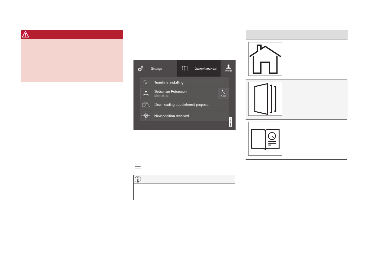
Navigating in the digital owner's manual
The digital on-board owner's manual is
accessed from the center display. The contents
are searchable and it is easy to navigate among
the various sections.
The digital on-board owner's manual is accessed from
the center display's Top view
Opening the digital owner's information
–
To open the digital owner's information, pull
down the center display's Top view and tap
Owner's manual.
There are several ways of finding information.
To access the owner's manual's menu, tap
in the upper bar.
Page 19
INTRODUCTION
}}
17
Searching using categories
The articles in the owner's
manual are structured in main
and sub-categories. The same
article may appear in several
pertinent categories in order to
make them easier to find.
1.
Tap
followed by Categories.
> The main categories will be listed.
2.
Tap a main category (
).
>
A list of sub-categories and (
) and arti-
cles (
) will be displayed.
3. Tap an article to open it. Tap the left arrow to
go back.
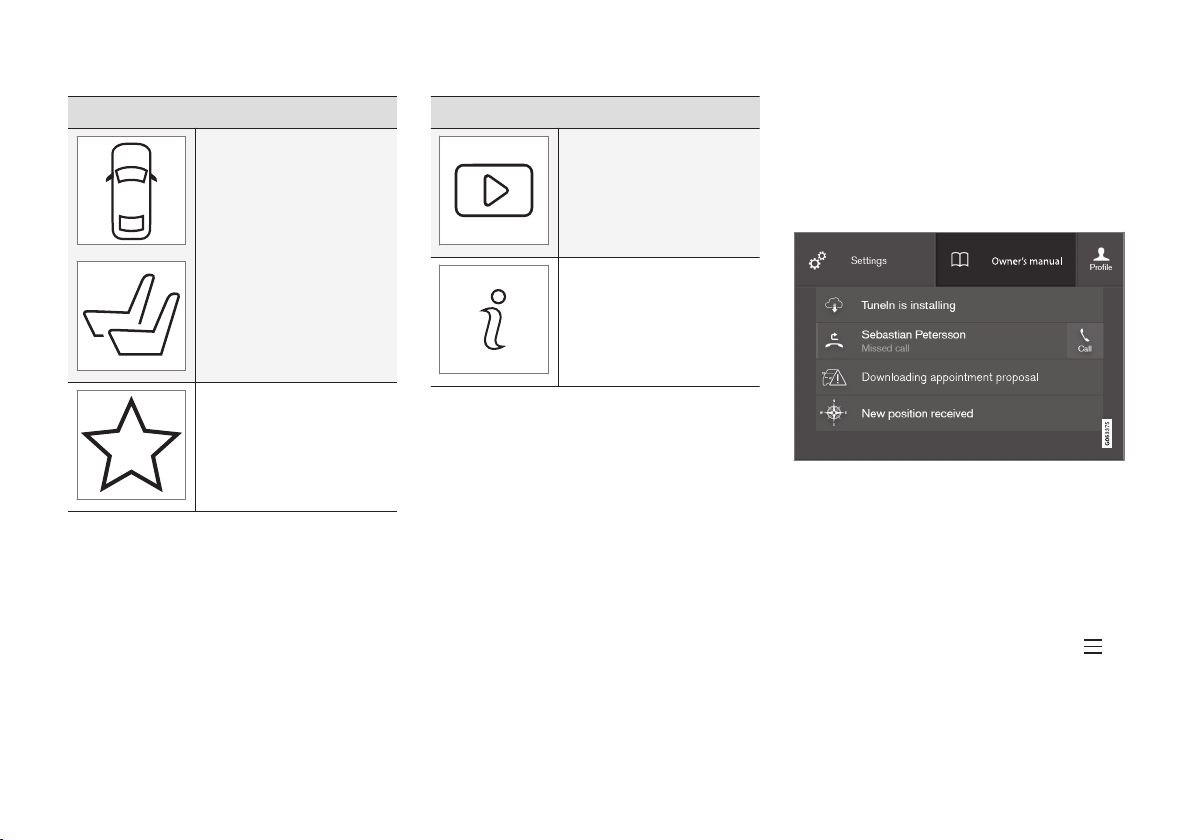
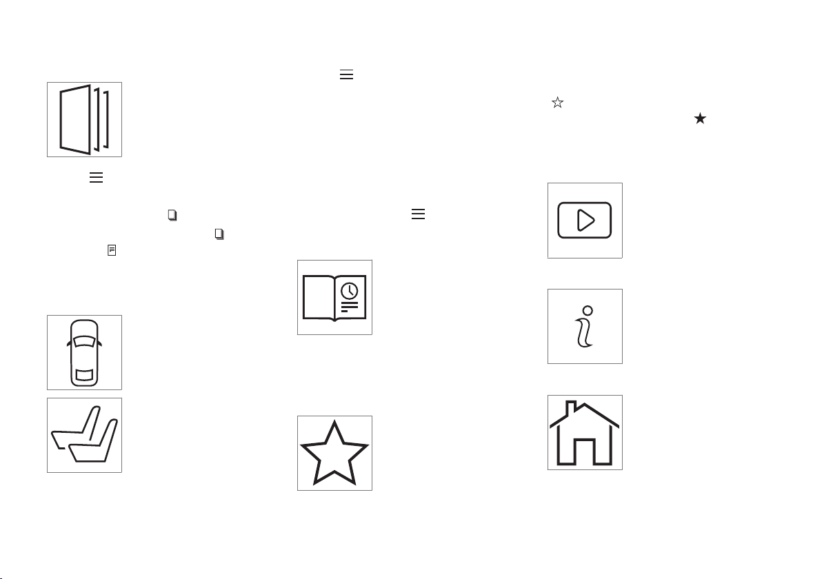
Interior and exterior hotspots
Exterior and interior views of
the vehicle where certain components are pointed out are
called hotspots.
1.
Tap
followed by Exterior/Interior.
> Exterior/interior views will be displayed
with hotspots, which lead to relevant articles. Swipe the screen horizontally to
scroll among the views.
2. Tap a hotspot.
> The title of a relevant article will be dis-
played.
3. Tap the title to open the article. Tap the left
arrow to go back or to begin a new
search.
Quick Guide
The heading Quick Guide in
the owner's manual's menu
leads to a selection of articles
that may be helpful in familiarizing you with your vehicle's most
common features and func-
tions. These articles can also
be found through categories but have been gathered here for quick access. Tap an article to read
it in its entirety.
Favorites
This is a list of articles that
have been saved as favorites.
Tap an article to read it in its
entirety.
Saving/deleting favorites
Save an article as a favorite by tapping the star
(
) at the upper right when an article is open.
The star symbol will be filled in (
) when its arti-
cle has been saved as a favorite.
To delete a favorite, tap its star again.
Video
Tap for short instructional videos for various vehicle functions.
Information
Tap the symbol for information
about the current version of the
owner's information in your
vehicle and other useful information.
Start page
Tap the symbol to come to the
owner's information start page.
Page 20
||
INTRODUCTION
18
Using the search function
1.
Tap the magnifying glass icon (
) in the
owner's manual's upper menu. A keyboard
will appear at the bottom of the screen.
2. Enter a word, e.g., "seat belt."
> Suggested articles will be displayed as
more characters are entered.
3. Confirm by tapping the article. To leave
search mode tap the up-arrow next to the
search box.
Related information
•
On-board digital owner's manual (p. 15)
•
Using the center display keyboard (p. 47)
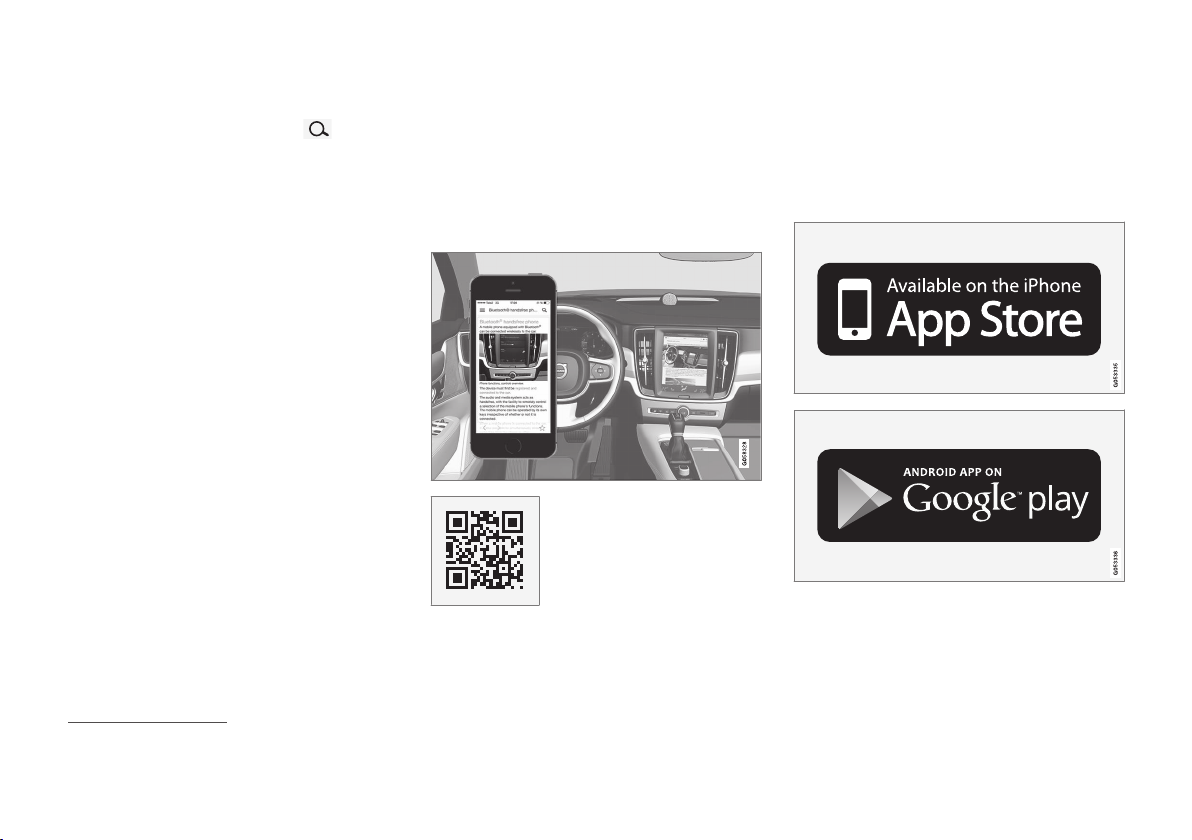
Owner's manual in mobile devices
Owner's information mobile app1 can be downloaded from the App Store and Google Play and
is adapted for both cell phones and tablets.
These apps also contain videos and interior/
exterior hotspot views of the vehicle that you can
click on for additional information.
This QR code will take you
directly to the app or you can
search for "Volvo manual" in
the App Store or Google Play.
The app contains videos and exterior/interior
views of the vehicle with certain components/
functions highlighted in hotspots, which lead
directly to related information. It is easy to navigate between the various categories and articles
and the contents are searchable.
The mobile app is available at the App Store and Google
Play
1
Certain models and mobile devices
Page 21

INTRODUCTION
19
Related information
•
Using the owner's manual (p. 20)
•
Additional information about your vehicle
(p. 19)
Additional information about your vehicle
Volvo Cars' website and support site provide
additional information about your vehicle.
Support on the Internet
Go to support.volvocars.com to visit the site,
which is available in most markets.
The information on the support site is searchable
and is grouped into different categories. It
includes support for e.g., Internet-based services
and functions, Volvo On Call, the navigation system and apps. Video and step-by-step instructions explain various procedures such as how to
connect the vehicle to the Internet via a cell
phone.
Downloadable information
Maps
Sensus Navigation system maps can be downloaded from the support site.
Mobile apps
Beginning with model year 2014, the owner's
manual is available in the form of an app for certain Volvo models. The Volvo On Call app can
also be found here.
Owner's manuals for earlier model Volvos
Owner's manuals for earlier model Volvos are
available in PDF format. Quick Guides and supplements can also be found on the support site.
Select a model and a model year and download
the desired information.
Contact
Contact information for customer support and the
nearest Volvo retailer are available on the site.
Related information
•
Using the owner's manual (p. 20)
•
On-board digital owner's manual (p. 15)
•
Volvo ID (p. 25)
Page 22
INTRODUCTION
20
Using the owner's manual
Reading your owner's manual is a good way of
familiarizing yourself with the features and systems in your vehicle.
On-board owner's manual
Reading the owner's manual is a good way to
become familiar with your vehicle and to learn to
utilize the features and functions that it offers.
Pay particular attention to the warnings provided.
Volvo reserves the right to make model changes
at any time, or to change specifications or design
without notice and without incurring obligation.
© Volvo Car Corporation
Printed owner's information
We advise keeping printed owner's information in
the vehicle for quick access to necessary information and how to contact Volvo if help is
required.
Illustrations
Some of the illustrations and images used in your
owner's information may be generic and are
intended to provide a general view or an example
of a certain feature or function. The features or
functions in the illustrations may differ slightly
from the equipment in your vehicle depending on
the level of instrumentation or market.
Options and accessories
Optional or accessory equipment described in
this manual is indicated by an asterisk.
Optional or accessory equipment may not be
available in all countries or markets. Please note
that some vehicles may be equipped differently,
depending on special legal requirements.
Contact your Volvo retailer for additional information.
Footnotes
Certain pages of this manual contain information
in the form of footnotes at the bottom of the
page. This information supplements the text that
the footnote number refers to (a letter is used if
the footnote refers to text in a table).
Messages
There are several displays in the vehicle that
show messages generated by various systems
and functions in the vehicle. The appearance of
these texts differs slightly from normal texts (for
example:
Phone, Accept).
Decals
There are various types of decals in the vehicle
whose purpose is to provide important information in a clear and concise way. The importance
of these decals is explained as follows, in
descending order of importance.
Risk of injury
Black ISO symbols on a yellow warning background, white text/image on a black background.
Decals of this type are used to indicate potential
danger. Ignoring a warning of this type could
result in serious injury or death.
Page 23
INTRODUCTION
}}
21
Risk of damage to the vehicle
White ISO symbols and white text/image on a
black or blue warning background and space for
a message. If the information on decals of this
type is ignored, damage to the vehicle could
result.
Information
White ISO symbols and white text/image on a
black background. These decals provide general
information.
NOTE
The decals shown in the Owner’s Manual are
examples only and are not intended to be
reproductions of the decals actually used in
the vehicle. The purpose is to give an indication of how they look and their approximate
location in the vehicle. The applicable information for your particular vehicle can be
found on the respective decals in the vehicle.
Types of lists
Procedures
Procedures (step-by-step instructions), or actions
that must be carried out in a certain order, are
arranged in numbered lists in this manual.
If there is a series of illustrations associated
with step-by-step instructions, each step in
the procedure is numbered in the same way
as the corresponding illustration.
Lists in which letters are used can be found
with series of illustrations in cases where the
order in which the instructions are carried out
is not important.
Arrows with or without numbers are used to
indicate the direction of a movement.
Arrows containing letters are used to indicate movement.
If there are no illustrations associated with a
step-by-step list, the steps in the procedure are
indicated by ordinary numbers.
Position lists
Red circles containing a number are used in
general overview illustrations in which certain
components are pointed out. The corresponding number is also used in the position
list's description of the various components.
Bullet lists
Bullets are used to differentiate a number of
components/functions/points of information that
can be listed in random order.
For example:
•
Coolant
•
Engine oil
Related information
Related information offers references to articles
containing information associated with the information that you are currently reading.
Continues on next page
} }This symbol can be found at the lower right
corner to indicate that the current topic continues
on the following page.
Page 24

||
INTRODUCTION
22
Continuation from previous page
|| This symbol can be found at the upper left
corner to indicate that the current topic is a continuation from the previous page.
Related information
•
On-board digital owner's manual (p. 15)
•
Owner's manual in mobile devices (p. 18)
•
Additional information about your vehicle
(p. 19)
Crash event data
This vehicle is equipped with an event data
recorder (EDR). The main purpose of an EDR is
to record, in certain crash or near crash-like situations, such as an air bag deployment or hitting
a road obstacle, data that will assist in understanding how a vehicle's systems performed.
The EDR is designed to record data related to
vehicle dynamics and safety systems for a short
period of time, typically 30 seconds or less. The
EDR in this vehicle is designed to record such
data as:
•
How various systems in your vehicle were
operating;
•
Whether or not the driver and passenger
safety belts were buckled/fastened;
•
How far (if at all) the driver was depressing
the accelerator and/or brake pedal; and,
•
How fast the vehicle was traveling.
These data can help provide a better understanding of the circumstances in which crashes and
injuries occur.
EDR data are recorded by your vehicle only if a
non-trivial crash situation occurs; no data are
recorded by the EDR under normal driving conditions and the EDR never registers who is driving
the vehicle or the location of a crash or a near
crash-like situation. However, other parties, such
as law enforcement, could combine the EDR data
with the type of personally identifying data rou-
tinely acquired during a crash investigation. To
read data recorded by an EDR, special equipment
is required, and access to the vehicle or the EDR
is needed.
Furthermore, your vehicle is equipped with a
number of computers whose task is to continuously control and monitor the vehicle’s operation.
They can also register some of this information
during normal driving conditions, most importantly
if they detect a fault relating to the vehicle’s operation and functionality or upon activation of the
vehicle’s active safety systems (e.g. City Safety
and the auto-brake function). Some of the registered information is required by technicians when
carrying out service and maintenance to enable
them to diagnose and rectify any faults that have
occurred in the vehicle and to enable Volvo to fulfill legal and other regulatory requirements. Information thus registered in the vehicle is registered
in the vehicle’s computers until the vehicle is
serviced or repaired. In addition to the above, the
registered information may – on an aggregated
basis – be used for research and product development purposes in order to continuously
improve the safety and quality of Volvo vehicles.
For additional information, contact:
In the United States
Volvo Car USA, LLC
Customer Care Center
1 Volvo Drive, P.O. box 914
Page 25

INTRODUCTION
}}
23
Rockleigh, New Jersey 07647
1-800-458-1552
www.volvocars.com/us
In Canada
Volvo Car Canada Ltd.
Customer Care Centre
9130 Leslie Street
Richmond Hill, Ontario L4B 0B9
1-800-663-8255
www.volvocars.com/ca
Options, accessories and the Onboard Diagnostic (OBDII) socket
We strongly recommend that Volvo owners
install only genuine, Volvo-approved accessories, and that accessory installations be performed only by a trained and qualified Volvo
service technician.
Optional or accessory equipment described in
this manual is indicated by an asterisk.
Optional or accessory equipment may not be
available in all countries or markets. Please note
that some vehicles may be equipped differently,
depending on special legal requirements.
Contact your Volvo retailer for additional information.
NOTE
•
Do not export your Volvo to another
country before investigating that country's applicable safety and exhaust emission requirements. In some cases it may
be difficult or impossible to comply with
these requirements. Modifications to the
emission control system(s) may render
your Volvo not certifiable for legal operation in the U.S., Canada and other countries.
•
All information, illustrations and specifications contained in this manual are based
on the latest product information available at the time of publication. Please note
that some vehicles may be equipped differently, depending on market-specific
adaptations or special legal requirements.
Optional equipment described in this
manual may not be available in all markets.
•
Some of the illustrations shown are
generic and are intended as examples
only, and may not depict the exact model
for which this owner's information is
intended.
•
Volvo reserves the right to make model
and product changes at any time, or to
change specifications or design without
notice and without incurring obligation.
Page 26
||
INTRODUCTION
24
WARNING
If your vehicle is involved in an accident,
unseen damage may affect its drivability and
safety.
WARNING
CALIFORNIA proposition 65
Engine exhaust, some of its constituents, and
certain vehicle components contain or emit
chemicals known to the state of California to
cause cancer, and birth defects or other
reproductive harm. In addition, certain fluids
contained in vehicles and certain products of
component wear contain or emit chemicals
known to the State of California to cause cancer, and birth defects or other reproductive
harm.
WARNING
Certain components of this vehicle such as air
bag modules, seat belt pretensioners, adaptive steering columns, and button cell batteries may contain Perchlorate material. Special
handling may apply for service or vehicle end
of life disposal.
See www.dtsc.ca.gov/hazardouswaste/
perchlorate.
•
Genuine Volvo accessories are tested to
ensure compatibility with the performance,
safety, and emission systems in your vehicle.
Additionally, a trained and qualified Volvo
service technician knows where accessories
may and may not be safely installed in your
Volvo. In all cases, please consult a trained
and qualified Volvo service technician before
installing any accessory in or on your vehicle.
•
Accessories that have not been approved by
Volvo may or may not be specifically tested
for compatibility with your vehicle. Additionally, an inexperienced installer may not be
familiar with some of your car's systems.
•
Any of your car's performance and safety
systems could be adversely affected if you
install accessories that Volvo has not tested,
or if you allow accessories to be installed by
someone unfamiliar with your vehicle.
•
Damage caused by unapproved or improperly
installed accessories may not be covered by
your new vehicle warranty. See your Warranty
and Service Records Information booklet for
more warranty information. Volvo assumes no
responsibility for death, injury, or expenses
that may result from the installation of nongenuine accessories.
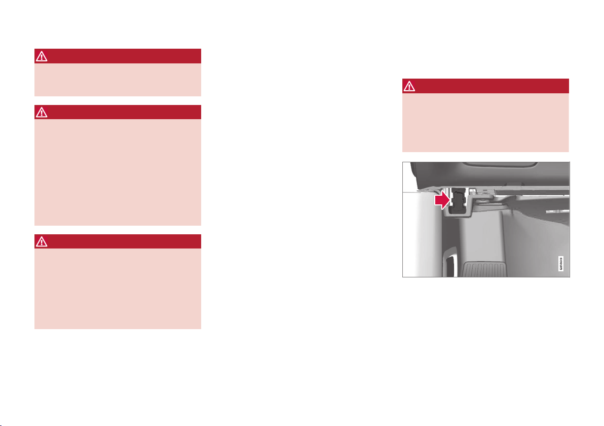
Connecting equipment to the On-board Diagnostic (OBDII) socket
WARNING
Volvo Cars takes no responsibility for the consequences of connecting non-authorized
equipment to the On-board Diagnostic
(OBDII) socket. This socket should only be
used by a trained and qualified Volvo service
technician.
The diagnostic socket OBDII under the dashboard on
the driver's side
Page 27

INTRODUCTION
25
Type approval
USA
FCC ID: 2AGKKACUII-06
This device complies with Part 15 of the FCC
rules. Operation is subject to the following two
conditions:
(1) This device may not cause harmful interference, and
(2) this device must accept any interference
received, including interference that may cause
undesired operation.
WARNING
Changes or modifications not expressly
approved by the party responsible for compliance could void the user's authority to operate the equipment.
Canada
IC: 20839-ACUII06
This device complies with Industry Canada
licence-exempt RSS standard(s). Operation is
subject to the following two conditions:
(1) this device may not cause interference, and
(2) This device must accept any interference
received, including interference that may cause
undesired operation.
Volvo ID
A Volvo ID can be used to access a number of
online services
2
Creating a Volvo ID
A Volvo ID can be created in two ways:
Using the Volvo ID app
1. If you have not already done so, download
the Volvo ID app from the
Download
Center.
2. Start the app and register a personal email
address.
3. Follow the instructions that will be sent automatically to this email address.
> A Volvo ID has now been created and has
been automatically registered to the vehicle. The Volvo ID services available can
now be used.
Using the Volvo On Call app
1. Download the latest version of the Volvo On
Call app to your cell phone from e.g., the App
Store, Windows Phone or Google Play.
2. Start the app and create a Volvo ID on the
start page.
3. Register a personal email address and then
follow the instructions that will be sent automatically to this address.
Registering your Volvo ID to the vehicle
If your Volvo ID was created using the Volvo On
Call mobile app, the ID has to be registered to
the vehicle:
1. With the vehicle connected to the Internet,
download the Volvo ID app from the
Download Center in the center display's
App view. See also the article "Downloading,
updating and uninstalling apps."
2. Start the app and enter your Volvo ID.
3. Follow the instructions that will be sent automatically to the email address linked to your
Volvo ID.
> Your Volvo ID is now registered to the
vehicle and the Volvo ID services available
can be used.
Advantages of having a Volvo ID
•
Only one user name and password are
required to access online services.
•
If you change a user name or password for
one of the online service (e.g., Volvo On Call),
it/they will also be automatically changed for
the other services.
Related information
•
Downloading, updating and uninstalling apps
(p. 438)
•
Connecting to the Internet (p. 434)
2
These services vary and may be subject to change. Consult your Volvo retailer.
Page 28

INTRODUCTION
* Option/accessory.
26
Volvo and the environment
Volvo is committed to the well-being of its customers. As a natural part of this commitment, we
care about the environment in which we all live.
Concern for the environment means an everyday
involvement in reducing our environmental
impact.
Volvo's environmental activities are based on a
holistic view, which means we consider the overall environmental impact of a product throughout
its complete life cycle. In this context, design, production, product use, and recycling are all important considerations. In production, Volvo has
partly or completely phased out several chemicals
including CFCs, lead chromates, asbestos, and
cadmium; and reduced the number of chemicals
used in our plants 50% since 1991.
Volvo was the first in the world to introduce into
production a three-way catalytic converter with a
Lambda sond, now called the heated oxygen sensor, in 1976. The current version of this highly
efficient system reduces emissions of harmful
substances (CO, HC, NOx) from the exhaust pipe
by approximately 95 – 99% and the search to
eliminate the remaining emissions continues.
Volvo is the only automobile manufacturer to
offer CFC-free retrofit kits for the air conditioning
system of all models as far back as the 1975
model 240. Advanced electronic engine controls
and cleaner fuels are bringing us closer to our
goal. In addition to continuous environmental
refinement of conventional gasoline-powered
internal combustion engines, Volvo is actively
looking at advanced technology alternative-fuel
vehicles.
When you drive a Volvo, you become our partner
in the work to lessen the car's impact on the
environment. To reduce your vehicle's environmental impact, you can:
•
Maintain proper air pressure in your tires.
Tests have shown decreased fuel economy
with improperly inflated tires.
•
Follow the recommended maintenance
schedule in your Warranty and Service
Records Information booklet.
•
Drive at a constant speed whenever possible.
•
See a trained and qualified Volvo service
technician as soon as possible for inspection
if the check engine (malfunction indicator)
light illuminates, or stays on after the vehicle
has started.
•
Properly dispose of any vehicle-related waste
such as used motor oil, used batteries, brake
pads, etc.
•
When cleaning your vehicle, please use genuine Volvo car care products. All Volvo car
care products are formulated to be environmentally friendly.
Related information
•
Driving economically (p. 387)
IntelliSafe—driver support
IntelliSafe is Volvo's philosophy regarding vehicle safety. It encompasses a number of systems,
both standard and optional, that are designed to
help make driving and traveling in a Volvo safer.
Support
Systems that help make driving safer are an integral part of IntelliSafe. These include optional
features such as Adaptive Cruise Control* that
helps maintain a set distance to a vehicle ahead,
Park Assist Pilot*, which assists in parking the
vehicle, Cross Traffic Alert*, Blind Spot
Information*, etc.
Accident prevention
Systems such as City Safety are designed to
automatically apply the brakes in situations in
which the driver does not have time to react.
Lane Keeping Aid* alerts the driver if the vehicle
inadvertently crosses a lane's/road's side marker
line.
Protection
The vehicle is equipped with e.g., seat belt pretensioners that pull the seat belts taut in critical
situations when there is a collision risk and
numerous airbags designed to help provide cushioning if certain types of collisions should occur.
Related information
•
Adaptive Cruise Control (ACC)* (p. 260)
•
Park Assist Pilot (PAP)* (p. 346)
Page 29

INTRODUCTION
* Option/accessory.
27
•
High and low beam headlights (p. 135)
•
Cross Traffic Alert (CTA)* (p. 311)
•
Blind Spot Information (BLIS)* (p. 309)
•
City Safety™ (p. 297)
•
Driving lane assistance (p. 320)
•
Airbag system (p. 67)
•
Roll stability control (RSC) (p. 243)
•
Seat belts (p. 62)
•
General safety information (p. 58)
Page 30

INTRODUCTION
28
Sensus
Sensus is the core of your personal Volvo experience and provides information, entertainment
and features that make owning your vehicle easier.
This is Sensus
Sensus provides an intelligent interface and
Internet-connected service with an intuitive navigation structure that offers access to relevant
information when it is needed, with minimal distractions.
Sensus also includes all of your vehicle's solutions relating to entertainment, connecting to the
Internet, navigation and the user interface
between the driver and the vehicle. Sensus
makes communication between you, the vehicle
and the digital world around you possible.
Page 31

INTRODUCTION
}}
* Option/accessory.
29
Information when it's needed, where it's needed
Information is presented in different displays depending on how it should be prioritized (generic illustration)
Head-up-display*
The head up-display presents types of information that the driver should be aware of immedi-
ately, such as traffic warnings, speed information
and navigation. Road sign information and incoming phone calls are also displayed here. The
head-up display is controlled from the right-side
steering wheel keypad and the center display.
Instrument panel
12" instrument panel
Page 32

||
INTRODUCTION
* Option/accessory.
30
8" instrument panel
The instrument panel displays information such
as speed, an incoming phone call or the track
that is currently playing. It is controlled using both
steering wheel keypads.
Center display
Many of the vehicle's main functions are controlled from the center display, a touchscreen that
reacts to taps or other gestures. The number of
physical buttons is thereby minimized. The screen
can be operated with or without gloves.
The center display is used to control e.g., the climate and infotainment systems and to adjust the
power seats*. The information shown here can be
dealt with by the driver or the front seat passenger.
Voice control system
The voice control system enables the driver to operate certain vehicle functions without
removing his/her hands from
the steering wheel and it
understands natural speech.
Use voice commands to e.g.,
play a track on the infotainment system, make a
phone call, raise the passenger compartment
temperature or to read a text message.
For additional information about all of the functions/system, see the respective articles in the
on-board owner's manual or the printed supplement.
Related information
•
Using the center display (p. 34)
•
Center display overview (p. 32)
•
Navigating in the center display's views
(p. 38)
•
Head-up display (HUD)* (p. 111)
•
Instrument panel (p. 91)
•
Voice control (p. 114)
Page 33

INTRODUCTION
* Option/accessory.
31
Glass
Laminated glass
The windshield and panoramic roof* are made of
laminated glass, which is reinforced to help prevent break-ins and to provide additional soundproofing. Laminated glass is optional for the
other side windows.
Laminated glass symbol
3
Related information
•
Laminated panoramic roof (p. 155)
•
Power windows (p. 147)
•
Defrosting windows and mirrors (p. 190)
•
Using sun curtains* (p. 149)
•
Rearview mirror (p. 152)
•
Power windows (p. 147)
•
Head-up display (HUD)* (p. 111)
•
Activating/deactivating the rain sensor
(p. 145)
•
Windshield and headlight washers (p. 146)
3
This symbol is not shown on the windshield or panoramic roof.
Page 34

INTRODUCTION
32
Center display overview
Many of the vehicle's functions are controlled
from the center display.
Three of the center display's basic views. Swipe to the right/left to access the Function/App view (generic illustration)
Page 35

INTRODUCTION
* Option/accessory.
33
Function view: vehicle functions can be activated/deactivated by tapping. Certain functions are called "trigger functions", which
open settings windows, e.g.,
Camera and
parking functions. Settings for the head-up
display* are also started from Function view
but the actual interaction is controlled from
the steering wheel keypad buttons and the
instrument panel.
Home view: the initial view shown when the
center display is started.
App (Application) view: shows apps that have
been downloaded (third-party apps) as well
as ones for integrated functions such as
FM
radio
. Tap an icon to open the app.
Status bar: vehicle activities are shown at the
top of the screen. Network/connection information is shown on the left side of the bar.
Media-related information, the clock and
information about background activities are
shown to the right.
Top view: pull down the tab to open Top view.
From here, you can access
Settings,
Owner's manual and stored messages.
Navigation: leads to map navigation. Tap the
sub-view to expand it.
Media: the most recently used media-related
apps. Tap the sub-view to expand it.
Phone: used to access phone-related functions. Tap the sub-view to expand it.
The extra sub-view: the most recently used
apps/vehicle functions that do not belong in
any of the other sub-views are listed here.
Tap the sub-view to expand it.
Climate bar: information and direct access to
settings such as temperature, seat heating*
and blower speed. Tap the symbol at the
center of the Climate bar to open Climate
view for additional settings.
Related information
•
Using the center display (p. 34)
•
Function view buttons (p. 45)
•
Symbols in the center display status bar
(p. 43)
•
Settings view (p. 167)
•
Media player (p. 413)
•
Phone (p. 426)
•
Climate system controls in the center display
(p. 183)
•
Cleaning the center display (p. 521)
Page 36

INTRODUCTION
34
Using the center display
Many of the vehicle's functions can be controlled and settings can be made from the
screen in the center console, referred to in this
owner's information as the center display, which
is a touchscreen.
Using the center display's touchscreen functionality
Two people can interact with the screen at the
same time, e.g., to adjust the temperature for the
driver and passenger sides.
The screen reacts differently depending on
whether the user taps, drags or swipes on the
screen. This makes it possible to move between
views, mark objects, scroll in lists and move apps
by touching the screen in various ways. The following table lists the gestures that can be used
on the screen:
An infrared film on the screen enables it to react
if a finger is directly in front of the screen (but
not actually touching it). This makes it possible to
use the screen while wearing gloves.
CAUTION
Do not touch the screen with sharp objects
because this could cause scratches.
Procedure Gesture Result
Tap once. Marks an object, confirms a selection or activates a function.
Double-tap. Zooms in on an object such as a map.
Press and hold. "Grabs" an object so that it can be dragged. Press and hold on the screen and drag the object to the desired
position.
Tap with two fingers. Zooms out from an object such as a map.
Page 37

INTRODUCTION
}}
35
Procedure Gesture Result
Drag Moves between screen views, scrolls in a list, text or a view. Press and hold to drag apps or objects in a list.
Swipe Moves between screen views, scrolls in a list, text or a view
Stretch Zooms in.
Pinch Zooms out.
Page 38

||
INTRODUCTION
36
Turning off and reactivating the center display
Home button for the center display
When the center display is turned off, the screen
goes dark to avoid disturbing the driver. However,
the climate bar remains visible and apps or other
functions connected to the display remain active.
1. Press and hold the Home button below the
screen.
> The screen will go dark. However, the cli-
mate bar remains visible and apps or
other functions connected to the display
remain active. The screen can also be
cleaned while it is turned off.
2. Reactivate by pressing the Home button
briefly.
> The view that was displayed when the
screen was turned off will be displayed
again.
NOTE
•
The display cannot be turned off while a
message requiring action is on the
screen.
•
The display turns off automatically when
the ignition is switched off and the driver's door is opened.
Returning to Home view
1. Press the Home button briefly.
> The most recent Home view mode will be
displayed.
2. Press again briefly.
> All of the Home view's sub-views will
return to standard mode.
NOTE
From Home view's standard mode, press the
Home button to start animated on-screen
instructions describing how to display the various views.
Moving apps and vehicle function buttons
Apps and function buttons can be moved and
organized in their respective views.
1. Press and hold an app/button.
> The app/button will change size and
become transparent. It can then be
moved.
2. Drag the app/button to an available position
in the view.
A maximum of 48 lines can be utilized for placing
apps/buttons. To move an app/button outside of
the visible view, drag it to the bottom of the view.
A new line will then be added where the app/
button can be placed (this line may not be visible). Swipe the screen to scroll up or down in the
view to display information that may be outside of
the view.
Scrolling in lists, articles or views
A scroll indicator on the screen shows that it is
possible to scroll up or down in the view. Press
the indicator and move it up or down or swipe up
or down anywhere in the view.
Page 39

INTRODUCTION
37
The scroll indicator on the right side of the center display
Using center display controls
Temperature control
4
Digital controls are available for many of the vehicle's functions. For example, to set the temperature:
•
Drag the control to the desired temperature
•
Tap
+/− to raise or lower the temperature
incrementally, or
•
Tap the desired temperature on the control
Related information
•
Navigating in the center display's views
(p. 38)
•
Settings view (p. 167)
•
Sensus (p. 28)
•
Downloading, updating and uninstalling apps
(p. 438)
•
Using the center display keyboard (p. 47)
4
Generic illustration. The temperature in your vehicle may be set to degrees Fahrenheit.
Page 40

INTRODUCTION
38
Navigating in the center display's views
There are 5 different basic views in the center
display: Home view, Top view, Climate view, App
view and Function view. The display is activated
automatically when the driver's door is opened.
Home view
Home view is displayed when the screen is activated. It consists of four sub-views:
Navigation,
Media, Phone and an extra sub-view. The extra
sub-view contains the most recently used app/
vehicle function that is not related to the other
three sub-views. For example, if the most recently
used app/vehicle function is a music app, the
Media sub-view will be displayed.
The sub-views display brief information about the
respective apps.
The first time the vehicle is started, some of the
Home view's sub-views will not contain any information.
NOTE
In Home view's standard mode (reached by
pressing the Home button briefly), an animation explaining how to access the different
views will be shown on the screen.
NOTE
When the vehicle is moving:
•
Some functions (using the center display
keyboard, etc.) may be disabled.
•
Certain texts (e.g., those generated by
apps) will be truncated to three lines. Tap
the
Read out button to have the entire
text read aloud.
•
Text messages will be truncated to one
line. Tap the
Read out button to have
the entire text read aloud.
Page 41

INTRODUCTION
}}
39
Expanding a sub-view from the standard view
Standard view and an expanded sub-view in the center display
Page 42

||
INTRODUCTION
40
Expanding a sub-view:
–
To expand sub-view one, two or three: tap
the screen anywhere in the sub-view. When a
sub-view is expanded, the Home view's
fourth sub-view will temporarily not be displayed. The other two views will be minimized
and will only show limited information. Tapping the fourth sub-view will minimize the
other three sub-views and they will only show
limited information.
Expanding a sub-view provides access the
respective apps' basic functions.
Closing an expanded sub-view:
–
A sub-view can be closed in three different
ways:
•
Tap the upper section of the expanded
sub-view.
•
Tap one of the other sub-views (which will
then open in expanded view).
•
Press the Home button below the center
display briefly.
Opening/closing a sub-view in full-screen mode
The extra sub-view and the Navigation sub-view
can be opened in full-screen mode to show additional information and possible settings.
In expanded mode, open the
app in full-screen mode by tapping the symbol.
Tap on the symbol or the Home
button below the screen to
return to the expanded view.
It is always possible to return to Home view by
pressing the Home button. Press the Home button twice to return to Home view's standard view
from full-screen.
Home button for the center display
Status bar
Current vehicle activities are shown in the status
bar at the top of the screen. Network and connection information is shown to the left. Brief
information about currently running apps and the
clock are shown to the right.
Top view
The top view has a tab at the center of the status
bar. Pull down (expand) the Top view by swiping
the tab downward.
Top view when expanded
Top view provides access to:
•
Settings
•
Owner's manual
•
Profile
•
The vehicle's stored messages
Page 43

INTRODUCTION
}}
41
To leave (minimize) Top view, tap the screen outside of this view or tap at the bottom of Top view
and swipe upward. The views behind will become
visible again. Top view is not available when the
ignition is being started/switched off or when a
message is displayed on the screen.
Going to Top view from an app
To pull down Top view when an app is running
(e.g., FM radio):
•
Tap
FM Radio Settings to display these
settings.
•
Tap
Owner's manual to open an article
related to the specific app.
This applies only to your vehicle's factoryinstalled apps. This is not possible for third-
party apps that have been downloaded.
Climate view
The climate bar, where the most common climate
system settings can be made, is located at the
bottom of the screen and is always visible.
Tap the symbol at the center of the climate bar to open Climate view for
access to additional climate system
settings.
Tap the symbol to close Climate view
and return to a previous view.
App view
App view (generic illustration)
Swipe the screen from right to left to access App
view from Home view. This displays factory-installed apps such as
FM as well as any apps that
have been downloaded. Brief information will be
displayed for certain apps, for example missed
phone calls, etc.
Tap an app to open it.
When applicable, swipe downward to scroll in the
list of apps (depending on the number of apps
currently running).
To move an app, press and hold it. It will become
slightly bigger and transparent and can then be
dragged to the desired position and released.
Return to Home view by swiping the screen from
left to right or by pressing the Home button.
Function view
Function view (generic illustration)
Page 44

||
INTRODUCTION
42
Swipe the screen from left to right to access
Function view from Home view. From Function
view, you can activate/deactivate various vehicle
functions such as
Drive Modes, Speed Sign
Assist and Park Assist.
When applicable, swipe upward to scroll in the list
of functions (depending on the number of functions).
Activate/deactivate a function by tapping its button. Certain functions will open in their own windows.
To move a function button, press and hold it. It
will become slightly smaller and transparent and
can then be dragged to the desired position and
released.
Related information
•
Using the center display (p. 34)
•
Center display overview (p. 32)
•
Function view buttons (p. 45)
•
Symbols in the center display status bar
(p. 43)
•
Changing settings in different types of apps
(p. 52)
•
Climate system controls (p. 182)
Page 45

INTRODUCTION
}}
43
Symbols in the center display status bar
The following table provides an overview of the
symbols used in the center display's status bar.
The status bar shows current vehicle activities
and in certain cases, also their status. Due to limited space in the status bar, not all symbols will
be displayed at all times.
Symbol Meaning
Roaming activated.
Cell phone network signal strength.
Bluetooth device connected.
Bluetooth activated but no device
connected.
Connected to a Wi-Fi network.
Tethering activated. (Wi-Fi hotspot).
Vehicle modem activated.
Action in progress.
Preconditioning timer active (hybrid
models only)
Symbol Meaning
Audio source being played.
Audio source paused.
Phone call in progress.
Audio source muted.
News broadcasts from current radio
stationA.
Traffic information being receivedA.
Clock.
A
Not available in all markets.
Related information
•
Navigating in the center display's views
(p. 38)
•
Indicator symbols in the instrument panel
(p. 94)
•
Warning symbols in the instrument panel
(p. 97)
•
Messages in the instrument panel and center
display (p. 106)
Changing center display settings
The center display activates automatically when
the driver's door is opened. Settings can be
made for e.g., sounds, background and themes.
Turning off or changing the volume of center display sounds
System sounds in the center display can be
turned off or their volume can be changed:
1.
Tap
Settings in the center display's Top
view.
2.
Tap
Sound System Volumes.
3.
Pull the control under
Screen Touch to the
desired level to change volume or turn off
the sound for tapping the screen or Keypad
Touch.
Changing the screen's appearance (theme)
1.
Tap
Settings in the center display's Top
view.
2.
Tap
My Car Displays Display
Themes
.
3.
Select a theme, e.g.,
Minimalistic or
Chrome Rings.
In addition, the settings:
Normal and Bright can
also be selected. For Normal, the screen's background is dark and the text is light. This is the
default setting. If Bright is selected, the back-
Page 46

||
INTRODUCTION
44
ground will be light and the text will be dark,
which can increase readability in strong ambient
lighting.
These alternatives are always available and do
not shift automatically according to changes in
ambient lighting.
Related information
•
Using the center display (p. 34)
•
Sensus (p. 28)
•
Settings view (p. 167)
•
Cleaning the center display (p. 521)
Page 47

INTRODUCTION
}}
45
Function view buttons
The Function view, which is one of the center
display's basic views, contains all of the vehicle's
on-screen function buttons. From the Home
view, swipe from left to right on the screen to
come to the Function view.
Different types of buttons
There are three different types of vehicle function
buttons as listed in the following table.
Type of button Functions Vehicle function affected
Function buttons Have On/Off modes.
An LED indicator light to the left of the button's icon will illuminate when a function is
active. Press the button to turn the function on or off.
Most of the buttons in the function view are
function buttons.
Start buttons Do not have On/Off modes.
Pressing a start button opens a function's window, e.g., a window for adjusting the
driver's seat.
•
Camera.
•
Headrest fold.
•
Functions for folding down a seat.
•
Head-up display adjustments.
Parking buttons Have On/Off and scanning modes.
Similar to function buttons but have an additional parking scanning mode.
•
Park In.
•
Park Out.
Button modes
A function is activated (on) when the LED indicator is
green
A function is deactivated (off) when the LED indicator is
off
When a function or parking button's LED indicator is green, the function is activated. When a
function is initially activated, an additional text will
be displayed (certain functions only) in the button
for approx. 5 seconds, after which the button will
be displayed with the LED indicator illuminated.
Press the button briefly to deactivate the function.
Page 48

||
INTRODUCTION
46
The yellow triangle indicates that the function is not
working correctly
Related information
•
Center display overview (p. 32)
•
Navigating in the center display's views
(p. 38)
•
Categories in Settings view (p. 168)
Page 49

INTRODUCTION
}}
47
Using the center display keyboard
A keyboard can be used on the center display to
enter characters and search for e.g., destinations using the navigation system, adding contacts in phone book, etc. It is also possible to
use handwriting on the screen.
Entering text using the keyboard
The keyboard will only appear at the bottom of
the center display in situations when it is possible
to write on the screen.
NOTE
The keyboard cannot be used if the vehicle is
moving.
Page 50

||
INTRODUCTION
48
Keyboard function buttons (the appearance may vary depending on language settings, context, etc.)
Field for possible search hits. The word
changes as new letters are added. Scroll in
the list using the left/right arrows. Tap a
word to select it. The keyboard may not support all language selections, in which case
this line on the screen will not be displayed.
The characters that can be entered are language-dependent (see point 7). Tap a character to enter it.
Page 51

INTRODUCTION
}}
49
Several buttons (depending on the context
for which the keyboard is being used) will be
displayed here. In certain cases, it can be
used to enter @ (for an email address) or to
start a new line.
Press to hide the keyboard. In cases where
this is not possible, the button will not be displayed.
Tap once to enter one uppercase letter.
Double-tap for Caps lock (tap again to
return to lowercase letters). Letters entered
after the !, . and ? characters will automatically be uppercase. The first letter in the text
field or in text fields intended for names,
addresses or company names will also automatically be uppercase. The first letter in text
fields intended for passwords, web
addresses or email addresses will automatically be lowercase unless upper case is
chosen.
Press to display the numbers that can be
entered. When numbers are displayed, tap
to resume entering text or to
enter special characters.
Tap to change the keyboard language (in this
example, English is the selected language).
The characters available will change according to the selected language (2). This button
will only be displayed if several keyboard languages have been selected (see the section
"Changing keyboard languages" below).
Press and hold to display a list of possible
languages and tap a language to use it. To
add keyboard languages, see the heading
"Changing keyboard languages" below.
Tap to enter blank spaces.
Tap to erase one character at a time.
Tap to enable handwriting. See the section
"Handwritten text" below.
Tap the button above the keyboard to confirm the
text that has been entered (not shown in the
illustration). This button's appearance differs
depending on the context.
Changing keyboard languages
In order to change keyboard languages, they
must first be selected under
Settings.
The keyboard language can be changed without
changing the language used for the other systems/menus in the vehicle.
1. Pull down the center display's Top view and
tap
Settings.
2.
Tap
System Keyboard Layouts.
3. Select and one or more of the languages in
the list.
> This makes it possible to change the key-
board layout and characters available
depending on the language(s) selected.
When more than one language
has been selected, this button
(7) will appear on the keyboard.
To shift between keyboard languages by displaying the list of available languages:
1. Press and hold the button (7).
> A list will be displayed.
2. Tap the desired language. If more than four
languages have been selected in
Settings,
scroll in the list.
> The keyboard layout and characters avail-
able will change to the selected language.
To shift between keyboard languages without
displaying the list of available languages:
–
Tap the button (7).
> The keyboard will switch to the next lan-
guage in the list (without displaying the
list itself).
Page 52

||
INTRODUCTION
50
Special characters
To enter language-specific characters such as é
or è (if available):
1. Press and hold a character key.
> A box with available characters will open.
2. Tap the desired character. If none of the special characters is selected, the key's initial
character will be entered.
Handwritten text
Tap button (10), see the overview illustration
above, to enter the handwriting mode.
Area for entering characters.
Text box where the characters entered in
area (1) appear.
Suggested characters. Scroll in the list if
necessary.
Blank spaces.
Tap to erase one character at a time.
Tap to return to the standard keyboard.
Press to hide the keyboard. In cases where
this is not possible, the button will not be displayed.
Tap to change the keyboard language.
Entering characters
1. Enter a handwritten character (1) using a fingertip or by holding e.g., a pen near the
screen.
> Several character suggestions will appear
(3). The most likely character will be at the
top of the list.
CAUTION
Do not touch the screen with sharp objects
because this could cause scratches.
2. Continue entering characters.
> If no other choice is made, the character
at the top of the list will be used. Tap one
of the other characters in the list to use it
instead.
Page 53

INTRODUCTION
51
Erasing/changing handwritten characters
Erase a character by swiping over the handwriting area
(1)
Characters can be erased/changed in several
ways:
•
Tap the desired character in the list (3).
•
Tap button (5) to erase the character and
start again.
•
Sweep horizontally from right to left over the
handwriting area (1). Erase several characters by swiping over the area several times.
•
Tap the "x" in the text box (2) to delete all
characters.
New lines
Create a new line by drawing above the characters as
shown in the illustration
Blank spaces
Add a blank space by swiping from left to right
Related information
•
Using the center display (p. 34)
•
Center display overview (p. 32)
•
Navigating in the center display's views
(p. 38)
Page 54

INTRODUCTION
52
Changing settings in different types of apps
App view, which is one of the center display's
basic views, contains all of the vehicle's apps
(applications/programs). Access this view by
swiping the screen from right to left.
Basic apps
A number of apps are standard and are part of
Volvo Sensus, such as
FM Radio, USB and CD.
To change settings in a basic app:
1.
Open the app, for example
Phone, either on
the home screen or full-screen from App
view.
2. Pull down Top view.
3.
Tap
Phone settings.
4. Change the desired settings and confirm.
5. Press the Home button, tap the screen outside of Top view or pull Top view up.
Third-party apps
Third party apps have to be selected and downloaded. In these apps, setting are made from
within the app, not from Top view.
Volvo Structural Parts Statement
Volvo has always been and continues to be a
leader in automotive safety.
Volvo engineers and manufactures vehicles
designed to help protect vehicle occupants in the
event of a collision.
Volvos are designed to absorb the impact of a
collision. This energy absorption system including,
but not limited to, structural components such as
bumper reinforcement bars, bumper energy
absorbers, frames, rails, fender aprons, A-pillars,
B-pillars and body panels must work together to
maintain cabin integrity and protect the vehicle
occupants.
The supplemental restraint system including but
not limited to air bags, side curtain air bags, and
deployment sensors work together with the
above components to provide proper timing for
air bag deployment.
Due to the above, Volvo Car USA does not support the use of aftermarket, alternative or anything other than original Volvo parts for collision
repair.
Volvo Car USA also recommends using Volvoapproved replacement glass. The use of aftermarket glass, particularly a windshield, can have
an adverse effect on collision avoidance and
advanced lighting systems.
In addition Volvo does not support the use or reuse of structural components from an existing
vehicle that has been previously damaged.
Although these parts may appear equivalent, it is
difficult to tell if the parts have been previously
replaced with non-OE parts or if the part has
been damaged as a result of a prior collision. The
quality of these used parts may also have been
affected due to environmental exposure.
Related information
•
Crash event data (p. 22)
•
Contacting Volvo (p. 54)
Page 55

INTRODUCTION
}}
53
Driver distraction
Please keep the following warnings in mind
when operating/servicing your vehicle.
A driver has a responsibility to do everything possible to ensure his or her own safety and the
safety of passengers in the vehicle and others
sharing the roadway. Avoiding distractions is part
of that responsibility.
Driver distraction results from driver activities that
are not directly related to controlling the vehicle
in the driving environment. Your new Volvo is, or
can be, equipped with many feature-rich entertainment and communication systems. These
include hands-free cellular telephones, navigation
systems, and multipurpose audio systems. You
may also own other portable electronic devices
for your own convenience. When used properly
and safely, they enrich the driving experience.
Improperly used, any of these could cause a distraction.
For all of these systems, we want to provide the
following warning that reflects the strong Volvo
concern for your safety. Never use these devices
or any feature of your vehicle in a way that distracts you from the task of driving safely. Distraction can lead to a serious accident. In addition to
this general warning, we offer the following guidance regarding specific newer features that may
be found in your vehicle:
WARNING
•
Never use a hand-held cellular telephone
while driving. Some jurisdictions prohibit
cellular telephone use by a driver while
the vehicle is moving.
•
If your vehicle is equipped with a navigation system, set and make changes to
your travel itinerary only with the vehicle
parked.
•
Never program your audio system while
the vehicle is moving. Program radio presets with the vehicle parked, and use your
programmed presets to make radio use
quicker and simpler.
•
Never use portable computers or personal digital assistants while the vehicle
is moving.
Accessory installation
•
We strongly recommend that Volvo owners
install only genuine, Volvo-approved accessories, and that accessory installations be
performed only by a trained and qualified
Volvo service technician.
•
Genuine Volvo accessories are tested to
ensure compatibility with the performance,
safety, and emission systems in your vehicle.
Additionally, a trained and qualified Volvo
service technician knows where accessories
may and may not be safely installed in your
Volvo. In all cases, please consult a trained
and qualified Volvo service technician before
installing any accessory in or on your vehicle.
•
Accessories that have not been approved by
Volvo may or may not be specifically tested
for compatibility with your vehicle. Additionally, an inexperienced installer may not be
familiar with some of your car's systems.
•
Any of your car's performance and safety
systems could be adversely affected if you
install accessories that Volvo has not tested,
or if you allow accessories to be installed by
someone unfamiliar with your vehicle.
•
Damage caused by unapproved or improperly
installed accessories may not be covered by
your new vehicle warranty. See your Warranty
and Service Records Information booklet for
more warranty information. Volvo assumes no
responsibility for death, injury, or expenses
that may result from the installation of nongenuine accessories.
Page 56

||
INTRODUCTION
54
WARNING
The driver is always responsible for operating
the vehicle in a safe manner and for complying with current statutes and regulations.
It is also essential to maintain and service the
vehicle according to Volvo's recommendations
as stated in the owner's information and the
service and warranty booklet.
If the on-board information differs from the
printed owner's manual, the printed information always takes precedence.
Related information
•
Volvo Structural Parts Statement (p. 52)
Technician certification
In addition to Volvo factory training, Volvo supports certification by the National Institute for
Automotive Service Excellence (A.S.E.).
Certified technicians have demonstrated a high
degree of competence in specific areas. Besides
passing exams, each technician must also have
worked in the field for two or more years before a
certificate is issued. These professional technicians are best able to analyze vehicle problems
and perform the necessary maintenance procedures to keep your Volvo at peak operating condition.
Contacting Volvo
Use the following contact information if you
would like to get in touch with Volvo in the United States or Canada.
In the USA:
Volvo Car USA, LLC
Customer Care Center
1 Volvo Drive,
P.O. Box 914
Rockleigh, New Jersey 07647
1-800-458-1552
www.volvocars.com/us
In Canada:
Volvo Car Canada Ltd.
Customer Care Centre
9130 Leslie Street, Suite 101
Richmond Hill, Ontario L4B 0B9
1-800-663-8255
www.volvocars.com/ca
Page 57

INTRODUCTION
55
Volvo Roadside Assistance
Your new Volvo comes with a four year Volvo
Roadside Assistance program.
Additional information, features, and benefits of
this program are described in a separate information package in your glove compartment.
If you require assistance, dial:
In the U.S. 1-800-638-6586 (1-800-63-
VOLVO)
In Canada 1-800-263-0475
Page 58

Page 59

SAFETY
Page 60

SAFETY
58
General safety information
The vehicle is equipped with a number of safety
systems for the driver and passengers.
In the event of an accident, there are a number of
sensors in the vehicle that react and trigger
safety systems such as Roll Stability Control, airbags, seat belt pretensioners, etc., depending on
the severity of the collision. There are also
mechanical systems such as the Whiplash
Protection System.
Warning symbol in the instrument panel
The warning symbol in the instrument
panel illuminates when the ignition is in
mode II or higher. It will go out after
approx. 6 seconds if no faults are
detected in the airbag system.
WARNING
•
If the SRS warning light stays on after the
engine has started or if it illuminates
while you are driving, have the vehicle
inspected by a trained and qualified Volvo
service technician as soon as possible.
•
Never try to repair any component or part
of the SRS yourself. Any interference in
the system could cause malfunction and
serious injury. All work on these systems
should be performed by a trained and
qualified Volvo service technician.
If the dedicated warning symbol is not
functioning, the general warning symbol will illuminate instead and the same
message will be displayed in the instru-
ment panel.
Related information
•
Safety during pregnancy (p. 58)
•
Seat belts (p. 62)
•
Airbag system (p. 67)
•
Safety mode (p. 75)
•
Whiplash protection system (p. 59)
•
Child safety (p. 77)
Safety during pregnancy
The seat belt should always be worn during
pregnancy. However, it is crucial that it be worn
correctly.
The diagonal section should wrap over the shoulder then be routed between the breasts and to
the side of the belly. The lap section should lay
flat over the thighs and as low as possible under
the belly. It must never be allowed to ride upward.
Remove all slack from the belt and ensure that it
fits close to the body without any twists.
As a pregnancy progresses, pregnant drivers
should adjust their seats and steering wheel such
that they can easily maintain control of the vehicle as they drive (which means they must be able
to easily operate the foot pedals and steering
wheel). Within this context, they should strive to
position the seat with as large a distance as possible between their belly and the steering wheel.
Page 61

SAFETY
}}
* Option/accessory.
59
Related information
•
Buckling and unbuckling seat belts (p. 64)
•
Adjusting power front seats* (p. 121)
•
Manually operated front seats (p. 120)
Whiplash protection system
The Whiplash protection system (WHIPS) consists of specially designed hinges and brackets
on the front seat backrests designed to help
absorb some of the energy generated in a collision from the rear (when the vehicle is rearended).
Function
In the event of certain rear-end collisions, the
hinges and brackets of the front seat backrests
are designed to change position slightly to allow
the backrest/head restraint to help support the
occupant's head before moving slightly rearward.
This movement helps absorb some of the forces
that could result in whiplash.
WARNING
•
The WHIPS system is designed to supplement the other safety systems in your
vehicle. For this system to function properly, the three-point seat belt must be
worn. Please be aware that no system
can prevent all possible injuries that may
occur in an accident.
•
The WHIPS system is designed to function in certain collisions from the rear,
depending on the crash severity, angle
and speed.
WARNING
•
Occupants in the front seats must never
sit out of position. The occupant's back
must be as upright as comfort allows and
be against the seat back with the seat
belt properly fastened.
•
If your vehicle has been involved in a rearend collision, the front seat backrests
must be inspected by a trained and qualified Volvo service technician, even if the
seats appear to be undamaged. Certain
components in the WHIPS system may
need to be replaced.
•
Do not attempt to service any component
in the WHIPS system yourself.
WARNING
•
Boxes, suitcases, etc. wedged behind the
front seats could impede the function of
the Whiplash Protection System.
•
If the rear seat backrests are folded
down, cargo must be secured to prevent
it from sliding forward against the front
seat backrests in the event of a collision
from the rear. This could interfere with
the action of the Whiplash Protection
System.
Page 62

||
SAFETY
* Option/accessory.
60
Do not place any objects behind the front seats that
could impede the WHIPS function
WARNING
Any contact between the front seat backrests
and the folded rear seat or a rear-facing child
seat could impede the function of the WHIPS
system. If the rear seat is folded down, the
occupied front seats must be adjusted forward so that they do not touch the folded rear
seat.
Related information
•
General safety information (p. 58)
•
Rear Collision Warning (RCW) (p. 308)
•
Manually operated front seats (p. 120)
•
Power front seats* (p. 120)
Occupant safety
Safety is Volvo's cornerstone.
Volvo's concern for safety
Our concern for safety dates back to 1927 when
the first Volvo rolled off the production line.
Three-point seat belts (a Volvo invention), safety
cages, and energy-absorbing impact zones were
designed into Volvo vehicles long before it was
fashionable or required by government regulation.
We will not compromise our commitment to
safety. We continue to seek out new safety features and to refine those already in our vehicles.
You can help. We would appreciate hearing your
suggestions about improving automobile safety.
We also want to know if you ever have a safety
concern with your vehicle. Call us in the U.S. at:
1-800-458-1552 or in Canada at:
1-800-663-8255.
Occupant safety reminders
How safely you drive doesn't depend on how old
you are but rather on:
•
How well you see.
•
Your ability to concentrate.
•
How quickly you make decisions under
stress to avoid an accident.
The following suggestions are intended to help
you cope with the ever changing traffic environment.
•
Never drink and drive.
•
If you are taking any medication, consult your
physician about its potential effects on your
driving abilities.
•
Take a driver-retraining course.
•
Have your eyes checked regularly.
•
Keep your windshield and headlights clean.
•
Replace wiper blades when they start to
leave streaks.
•
Take into account the traffic, road, and
weather conditions, particularly with regard to
stopping distance.
•
Never send text messages while driving.
•
Refrain from using or minimize the use of a
cell phone while driving.
Related information
•
Recall information (p. 62)
•
Reporting safety defects (p. 61)
Page 63

SAFETY
61
Reporting safety defects
The following information will help you report any
perceived safety-related defects in your vehicle.
Reporting safety defects in the U.S.
If you believe that your vehicle has a
defect which could cause a crash or
could cause injury or death, you should
immediately inform the National Highway Traffic Safety Administration
(NHTSA) in addition to notifying Volvo
Car USA, LLC. If NHTSA receives similar complaints, it may open an investigation, and if it finds that a safety
defect exists in a group of vehicles, it
may order a recall and remedy campaign. However, NHTSA cannot
become involved in individual problems
between you, your retailer, or Volvo Car
USA, LLC. To contact NHTSA, you may
either call the Auto Safety Hotline tollfree at
1-888-327-4236
(TTY: 1-800-424-9153) or write to:
NHTSA, U.S. Department of Transportation, Washington D.C. 20590.
You can also obtain other information
about motor vehicle safety from http://
www.safercar.gov, where you can also
enter your vehicle's VIN (Vehicle Identification Number) to see if it has any
open recalls.
Volvo strongly recommends that if your
vehicle is covered under a service campaign, safety or emission recall or similar action, it should be completed as
soon as possible. Please check with
your local retailer or Volvo Car USA,
LLC if your vehicle is covered under
these conditions.
NHTSA can be reached at:
Internet:
http://www.nhtsa.gov
Telephone:
1-888-DASH-2-DOT
(1-888-327-4236).
Reporting safety defects in Canada
If you believe your vehicle has a defect that could
cause a crash or could cause injury or death, you
should immediately inform Transport Canada in
addition to notifying Volvo Car Canada Ltd.
Transport Canada can be contacted at:
1-800-333-0510
Teletypewriter (TTY): 613 990-4500
Fax: 1-819-994-3372
Mailing Address: Transport Canada - Road
Safety, 80 rue Noël, Gatineau, (Quebec) J8Z 0A1
Related information
•
Recall information (p. 62)
•
Occupant safety (p. 60)
Page 64

SAFETY
62
Recall information
On our website, select the "Own" tab on the
upper left side of the screen and click the heading "Recall Information" on the right side of the
screen. Enter your Vehicle Identification Number
(VIN) for your vehicle (found at the base of the
windshield). If your vehicle has any open Recalls,
they will be displayed on this page.
You can also enter the Vehicle Identification
Number in the search field on the National
Highway Traffic Safety Administration's (NHTSA)
website at: www.nhtsa.gov.
Volvo customers in Canada
For any questions regarding open recalls for your
vehicle, please contact your authorized Volvo
retailer. If your retailer is unable to answer your
questions, please contact Volvo Customer Relations at 800-663-8255, Monday through Friday,
8:30 A.M. to 5:00 P.M. EST or volvocars.com/ca.
You may also write us at:
Volvo Car Canada Ltd.
Customer Care Centre
9130 Leslie Street, Suite 101
Richmond Hill, Ontario L4B 0B9
www.tc.gc.ca
Related information
•
Occupant safety (p. 60)
•
Reporting safety defects (p. 61)
Seat belts
Seat belts should always be worn by all occupants of your vehicle. Children should be properly restrained, using an infant, car, or booster
seat determined by age, weight and height.
Most states and provinces make it mandatory for
occupants of a vehicle to use seat belts.
Reversible seat belt pretensioners
Reversible seat belt pretensioners is a system in
the front seats that pulls the seat belts slightly
taut prior to a collision. This function helps position the front seat occupants to help improve the
effects of other safety systems, e.g., the airbag
system.
Seat belt maintenance
Check periodically that the seat belts are in good
condition. Use water and a mild detergent for
cleaning. Check seat belt mechanism function as
follows: attach the seat belt and pull rapidly on
the strap.
WARNING
•
Never repair the belt yourself; have this
work done by a trained and qualified
Volvo service technician only.
•
Any device used to induce slack into the
shoulder belt portion of the three-point
belt system will have a detrimental effect
on the amount of protection available to
you in the event of a collision.
•
The seat back should not be tilted too far
back. The shoulder belt must be taut in
order to function properly.
•
Do not use child safety seats or child
booster cushions/backrests in the front
passenger's seat. We also recommend
that children who have outgrown these
devices sit in the rear seat with the seat
belt properly fastened.
Related information
•
Buckling and unbuckling seat belts (p. 64)
•
Door and seat belt reminders (p. 66)
•
Seat belt pretensioners (p. 63)
Page 65

SAFETY
63
Seat belt pretensioners
The vehicle's seat belts are equipped with standard and electric pretensioners that can help pull
the seat belts taut in a critical situation or a collision. Some or all of the pretensioners will be
triggered in certain types of collisions, depending on the direction and severity of the impact.
Reversible seat belt pretensioners
Reversible seat belt pretensioners is a system in
the front seats that pulls the seat belts slightly
taut prior to a collision. This function helps position the front seat occupants to help improve the
effects of other safety systems, e.g., the airbag
system.
Seat belt pretensioners in collisions
The seat belts are equipped with standard pretensioners that are triggered according to the
severity of a collision.
Seat belt pretensioners in critical situations
In addition to the standard pretensioners, the
seat belts in the front seats are also equipped
with electric pretensioners.
The pretensioners interact and can be triggered
along with the City Safety and Rear Collision
Warning systems. In critical situations such as
sudden braking, evasive maneuvers, etc., the seat
belt can be pulled taut by the pretensioner's
electric motor.
The electric pretensioner positions the occupant
in the seat to help reduce the risk of striking the
interior of the passenger compartment and
improves the effect of other safety systems such
as the airbags.
Resetting the electric pretensioners
When a critical situation has passed, the seat belt
and the electric pretensioner are reset automatically.
If the seat belt should remain taut:
1. Stop the vehicle safely.
2. Unbuckle the seat belt and rebuckle it.
> The seat belt and the electric preten-
sioner will be reset.
WARNING
•
Never repair the belt yourself; have this
work done by a trained and qualified
Volvo service technician only.
•
Any device used to induce slack into the
shoulder belt portion of the three-point
belt system will have a detrimental effect
on the amount of protection available to
you in the event of a collision.
•
The seat back should not be tilted too far
back. The shoulder belt must be taut in
order to function properly.
•
Do not use child safety seats or child
booster cushions/backrests in the front
passenger's seat. We also recommend
that children who have outgrown these
devices sit in the rear seat with the seat
belt properly fastened.
Related information
•
Seat belts (p. 62)
•
Door and seat belt reminders (p. 66)
•
Buckling and unbuckling seat belts (p. 64)
Page 66

SAFETY
64
Buckling and unbuckling seat belts
Seat belts should be used by all occupants in
the vehicle when it is in motion.
Buckling a seat belt
1. Pull the belt out slowly. It should not be twisted or turned.
NOTE
Each seat belt is equipped with a seat belt
retractor that will lock up in the following situations:
•
if the belt is pulled out rapidly
•
during braking and acceleration
•
if the vehicle is leaning excessively
•
when driving in turns
•
if the Automatic Locking Retractor/Emergency Locking Retractor (ALR/ELR) is
activated (each seat belt (except for the
driver's belt) is equipped with the
ALR/ELR function, which is designed to
help keep the seat belt taut. ALR/ELR
activates if the seat belt is pulled out as far
as possible. If this is done, a sound from
the seat belt retractor will be audible,
which is normal, and the seat belt will be
pulled taut and locked in place. This function is automatically disabled when the
seat belt is unbuckled and fully retracted).
2. Insert the latch plate into the receptacle. The
seat belt retractor is normally "unlocked" and
you can move freely, provided that the shoulder belt is not pulled out too far.
> A distinct click will be audible.
WARNING
The seat belt latch plate should only be
inserted into its intended receptacle. Inserting
it into one of the other receptacles may prevent it from functioning properly.
3. The height of the seat belts in the front seats
can be adjusted. The height of the shoulder
section of the seat belt must be correctly
adjusted.
Press the button and move the upper seat
belt anchor up or down.
Position it as high as possible so that the
shoulder section of the belt is across the seat
occupant's collarbone and not across the
throat.
Page 67

SAFETY
65
The seat belt should be positioned over the shoulder
(not over the arm)
4. Tighten the lap section of the seat belt by
pulling the diagonal section upward toward
the shoulder.
The lap section of the belt must be positioned low on the
hips (not pressing against the abdomen)
Make sure that the shoulder belt is rolled up
into its retractor and that the shoulder and
lap belts are taut.
WARNING
Never use a seat belt for more than one
occupant. Never wear the shoulder portion of
the belt under the arm, behind the back or
otherwise out of position. Such use could
cause injury in the event of an accident. As
seat belts lose much of their strength when
exposed to violent stretching, they should be
replaced after any collision, even if they
appear to be undamaged.
Unbuckling the seat belt
To remove the seat belt, press the red section on
the seat belt receptacle. Before exiting the vehicle, check that the seat belt retracts fully after
being unbuckled. If necessary, guide the belt
back into the retractor slot.
Related information
•
Door and seat belt reminders (p. 66)
•
Seat belts (p. 62)
Page 68

SAFETY
66
Door and seat belt reminders
The door and seat belt reminders are intended
to alert all occupants of the vehicle that their
seat belts should be buckled before the vehicle
begins to move or if a door, the hood, trunk or
fuel filler door have not been closed properly.
Graphics in the instrument panel
Warning colors for doors/trunk vary depending on the
vehicle's speed (generic illustration)
The instrument panel graphic shows the seats
where seat belts are not buckled.
The same graphic also indicates if a door, the
hood, trunk or fuel filler door is/are open.
This graphic disappears automatically after
approx. 6 seconds or if the if the O button on the
steering wheel keypad is pressed.
Seat belt reminder
Seat belt reminder light in ceiling console
The seat belt reminder consists of an
audible signal, an indicator light near
the rearview mirror and a symbol in the
instrument panel that alert all occu-
pants of the vehicle to buckle their seat belts.
The audible signal is speed-dependent and will
sound for several seconds.
If the driver's or a passenger's seat belt is not
buckled, this will be indicated in the instrument
panel.
Child seats are not included in the seat belt
reminder system.
Front seats
An audible signal and an indicator light will
remind the driver and front seat passenger to
buckle their seat belts.
Rear seats
The rear seat belt reminder has two functions.
•
It indicates which seat belts are buckled in
the rear seats. This will also be displayed in
an instrument panel graphic. This graphic
can be erased by pressing the O button on
the steering wheel keypad.
•
It also provides audio and visual reminders if
a rear seat belt is unbuckled while the vehicle is in motion. The reminders will disappear
when the seat belt has been buckled again.
Door/hood/trunk/fuel filler door reminder
If a door, the hood, trunk or fuel filler door is/are
not properly closed, this will be indicated in a
graphic in the instrument panel. Stop the vehicle
safely and close the source of the reminder.
If the vehicle is moving at a speed
under approx.6 mph (10 km/h), the
information symbol will illuminate in the
instrument panel.
At speeds above approx. 6 mph
(10 km/h), the warning symbol will illuminate in the instrument panel.
Related information
•
Seat belts (p. 62)
•
Buckling and unbuckling seat belts (p. 64)
•
Seat belt pretensioners (p. 63)
Page 69

SAFETY
}}
67
Airbag system
As an enhancement to the three-point seat belts,
your vehicle is equipped with an airbag system.
WARNING
•
If the airbag warning light stays on after
the engine has started or if it illuminates
while you are driving, have the vehicle
inspected by a trained and qualified Volvo
service technician as soon as possible.
•
Never try to repair any component or part
of the airbag systems yourself. Any interference in the system could cause malfunction and serious injury. All work on
these systems should be performed by a
trained and qualified Volvo service technician.
WARNING
If your vehicle has become flood-damaged in
any way (e.g., soaked carpeting/standing
water on the floor of the vehicle), do not
attempt to start the vehicle. This may cause
airbag deployment which could result in serious injury. Have the vehicle towed to a trained
and qualified Volvo service technician for
repairs.
Before attempting to tow the vehicle:
1. Switch off the ignition for at least
10 minutes and disconnect the battery.
2. Follow the instructions for manually overriding the shiftlock system.
Deployed airbags
WARNING
If any of the airbags have deployed:
•
Do not attempt to drive the vehicle. Have
it towed to a qualified repair facility.
•
If necessary seek medical attentIon.
Driver/passenger side airbags
The front airbags supplement the three-point
seat belts. For these airbags to provide the protection intended, seat belts must be worn at all
times.
Driver and passenger side front airbags
The front airbag system
The front airbag system includes gas generators
surrounded by the airbags, and deceleration sensors that activate the gas generators, causing the
airbags to be inflated with nitrogen gas.
As the movement of the seats' occupants compresses the airbags, some of the gas is expelled
at a controlled rate to provide better cushioning.
Both seat belt pretensioners also deploy, minimizing seat belt slack. The entire process, including inflation and deflation of the airbags, takes
approximately one fifth of a second.
Page 70

||
SAFETY
68
The location of the front airbags is indicated by
SRS AIRBAG embossed on the steering wheel
pad and above the glove compartment, and by
decals on both sun visors and on the front and
far right side of the dash.
The driver's side front airbag is folded and
located in the steering wheel hub.
The knee airbag is folded on the underside of
the dashboard on the driver's side. The text
AIRBAG is embossed on the panel.
The passenger's side front airbag is folded
behind a panel located above the glove compartment.
WARNING
•
The airbags in the vehicle are designed to
be a SUPPLEMENT to–not a replacement for–the three-point seat belts. For
maximum protection, wear seat belts at all
times. Be aware that no system can prevent all possible injuries that may occur in
an accident.
•
Never drive with your hands on the steering wheel pad/airbag housing.
•
The front airbags are designed to help
prevent serious injury. Deployment occurs
very quickly and with considerable force.
During normal deployment and depending on variables such as seating position,
one may experience abrasions, bruises,
swellings, or other injuries as a result
from deployment of one or both of the
airbags.
•
When installing any accessory equipment,
make sure that the front airbag system is
not damaged. Any interference in the system could cause malfunction.
Front airbag deployment
•
The front airbags are designed to deploy during certain frontal or front-angular collisions,
impacts, or decelerations, depending on the
crash severity, angle, speed and object
impacted. The airbags may also deploy in
certain non-frontal collisions where rapid
deceleration occurs.
•
The airbag system sensors, which trigger the
front airbags, are designed to react to both
the impact of the collision and the inertial
forces generated by it, and to determine if
the intensity of the collision is sufficient for
the seat belt pretensioners and/or airbags to
be deployed.
However, not all frontal collisions activate the
front airbags.
•
If the collision involves a nonrigid object (e.g.,
a snow drift or bush), or a rigid, fixed object
at a low speed, the front airbags will not necessarily deploy.
•
Front airbags do not normally deploy in a
side impact collision, in a collision from the
rear or in a rollover situation.
•
The amount of damage to the bodywork
does not reliably indicate if the airbags
should have deployed or not.
Page 71

SAFETY
}}
69
NOTE
•
Deployment of front airbags occurs only
one time during an accident. In a collision
where deployment occurs, the airbags
and seat belt pretensioners activate.
Some noise occurs and a small amount
of powder is released. The release of the
powder may appear as smoke-like matter.
This is a normal characteristic and does
not indicate fire.
•
Volvo's front airbags use special sensors
that are integrated with the front seat
buckles. The point at which the airbag
deploys is determined by whether or not
the seat belt is being used, as well as the
severity of the collision.
•
Collisions can occur where only one of
the airbags deploys. If the impact is less
severe, but severe enough to present a
clear injury risk, the airbags are triggered
at partial capacity. If the impact is more
severe, the airbags are triggered at full
capacity.
WARNING
•
Do not use child safety seats or child
booster cushions/backrests in the front
passenger's seat. We also recommend
that occupants under 4 feet 7 inches
(140 cm) in height who have outgrown
these devices sit in the rear seat with the
seat belt fastened. See also the Occupant Weight Sensor information.
•
Never drive with the airbags deployed.
The fact that they hang out can impair the
steering of your vehicle. Other safety systems can also be damaged.
•
The smoke and dust formed when the
airbags are deployed can cause skin and
eye irritation in the event of prolonged
exposure.
Should you have questions about any component
in the SRS system, please contact a trained and
qualified Volvo service technician or Volvo customer support:
In the USA
Volvo Car USA, LLC
Customer Care Center
1 Volvo Drive
P.O. Box 914
Rockleigh, New Jersey 07647
1-800-458-1552
www.volvocars.com/us
In Canada
Volvo Car Canada Ltd.
Customer Care Centre
9130 Leslie Street, Suite 101
Richmond Hill, Ontario L4B 0B9
1-800-663-8255
www.volvocars.com/ca
Airbag decals
Airbag decal on the outside of both sun visors
Page 72

||
SAFETY
70
Passenger's side airbag decal
WARNING
•
Children must never be allowed in the
front passenger's seat.
•
Occupants in the front passenger's seat
must never sit on the edge of the seat, sit
leaning toward the instrument panel or
otherwise sit out of position.
•
The occupant's back must be as upright
as comfort allows and be against the seat
back with the seat belt properly fastened.
•
Feet must be on the floor, e.g., not on the
dash, seat or out of the window.
WARNING
•
No objects or accessory equipment, e.g.
dashboard covers, may be placed on,
attached to, or installed near the air bag
hatch (the area above the glove compartment) or the area affected by airbag
deployment.
•
There should be no loose articles, such
as coffee cups on the floor, seat, or dashboard area.
•
Never try to open the airbag cover on the
steering wheel or the passenger's side
dashboard. This should only be done by a
trained and qualified Volvo service technician.
•
Failure to follow these instructions can
result in injury to the vehicle occupants.
Related information
•
Seat belts (p. 62)
•
Occupant weight sensor (p. 70)
Occupant weight sensor
The Occupant Weight Sensor (OWS) is
designed to meet the regulatory requirements of
Federal Motor Vehicle Safety Standard (FMVSS)
208 and is designed to disable (will not inflate)
the passenger's side front airbag under certain
conditions.
Occupant Weight Sensor (OWS) indicator light
Disabling the passenger's side front airbag
Volvo recommends that ALL occupants (adults
and children) shorter than 4 feet 7 inches
(140 cm) be seated in the back seat of any vehicle with a front passenger side airbag and be
properly restrained for their size and weight.
The OWS works with sensors that are part of the
front passenger's seat and seat belt. The sensors
are designed to detect the presence of a properly
Page 73

SAFETY
}}
71
seated occupant and determine if the passenger's side front airbag should be enabled (may
inflate) or disabled (will not inflate).
The OWS will disable (will not inflate) the passenger's side front airbag when:
•
the front passenger's seat is unoccupied, or
has small/medium objects in the front seat,
•
the system determines that an infant is present in a rear-facing infant seat that is installed according to the manufacturer's instructions,
•
the system determines that a small child is
present in a forward-facing child restraint
that is installed according to the manufacturer's instructions,
•
the system determines that a small child is
present in a booster seat,
•
a front passenger takes his/her weight off of
the seat for a period of time,
•
a child or a small person occupies the front
passenger's seat.
The OWS uses a PASSENGER AIRBAG OFF
indicator lamp which will illuminate and stay on to
remind you that the passenger's side front airbag
is disabled. The PASSENGER AIRBAG OFF indicator lamp is located in the overhead console,
near the base of the rearview mirror.
NOTE
When the ignition is switched on, the OWS
indicator light will illuminate for several seconds while the system performs a self-diagnostic test.
However, if a fault is detected in the system:
•
The OWS indicator light will stay on
•
The SRS warning light will come on and stay
on and a text message will be displayed.
WARNING
If a fault in the system is detected and indicated as described, be aware that the passenger's side front airbag will not deploy in
the event of a collision. In this case, the SRS
system and Occupant Weight Sensor should
be inspected by a trained and qualified Volvo
service technician as soon as possible.
WARNING
•
Never try to open, remove, or repair any
components in the OWS system. This
could result in system malfunction. Maintenance or repairs should only be carried
out by an a trained and qualified Volvo
service technician.
•
The front passenger's seat should not be
modified in any way. This could reduce
pressure on the seat cushion, which
might interfere with the OWS system's
function.
Page 74

||
SAFETY
72
Passenger's
seat occupancy status
OWS indicator light
status
Passenger's
side front airbag status
Seat unoccupied
OWS indicator light
lights up.
Passenger's
side front airbag disabled
Seat occupied by low
weight occupant/object
A
OWS indicator light
lights up
Passenger's
side front airbag disabled
Seat occupied by heavy
occupant/
object
OWS indicator light is
not lit
Passenger's
side front airbag enabled
A
Volvo recommends that children always be properly restrained
in appropriate child restraints in the rear seats. Do not assume
that the passenger's side front airbag is disabled unless the
PASSENGER AIRBAG OFF indicator lamp is lit. Make sure the
child restraint is properly installed. If there is any doubt as to the
status of the passenger's side front airbag, move the child
restraint to the rear seat.
The OWS is designed to enable (may inflate) the
passenger's side front airbag in the event of a
collision anytime the system senses that a person of adult size is sitting properly in the front
passenger's seat. The PASSENGER AIRBAG
OFF indicator lamp will be off and remain off.
If a person of adult size is sitting in the front passenger's seat, but the PASSENGER AIRBAG
OFF indicator lamp is on, it is possible that the
person isn't sitting properly in the seat. If this
happens:
•
Turn the vehicle off and ask the person to
place the seatback in an upright position.
•
Have the person sit upright in the seat, centered on the seat cushion, with the person's
legs comfortably extended.
•
Restart the vehicle and have the person
remain in this position for about two minutes.
This will allow the system to detect that person and enable the passenger's frontal airbag.
•
If the PASSENGER AIRBAG OFF indicator
lamp remains on even after this, the person
should be advised to ride in the rear seat.
This condition reflects limitations of the OWS
classification capability. It does not indicate OWS
malfunction.
Modifications
If you are considering modifying your vehicle in
any way to accommodate a disability, for example
by altering or adapting the driver's or front passenger's seat(s) and/or airbag systems, please
contact Volvo at:
In the USA
Volvo Car USA, LLC
Customer Care Center
1 Volvo Drive
P.O. Box 914
Rockleigh, New Jersey 07647
1-800-458-1552
In Canada
Volvo Car Canada Ltd.
Customer Care Centre
9130 Leslie Street, Suite 101
Richmond Hill, Ontario L4B 0B9
1-800-663-8255
Page 75

SAFETY
73
WARNING
•
No objects that add to the total weight on
the seat should be placed on the front
passenger's seat. If a child is seated in
the front passenger's seat with any additional weight, this extra weight could
cause the OWS system to enable the airbag, which might cause it to deploy in the
event of a collision, thereby injuring the
child.
•
The seat belt should never be wrapped
around an object on the front passenger's seat. This could interfere with the
OWS system's function.
•
The front passenger's seat belt should
never be used in a way that exerts more
pressure on the passenger than normal.
This could increase the pressure exerted
on the weight sensor by a child, and
could result in the airbag being enabled,
which might cause it to deploy in the
event of a collision, thereby injuring the
child.
WARNING
•
Keep the following points in mind with
respect to the OWS system. Failure to
follow these instructions could adversely
affect the system's function and result in
serious injury to the occupant of the front
passenger's seat:
•
The full weight of the front seat passenger should always be on the seat cushion.
The passenger should never lift him/
herself off the seat cushion using the
armrest in the door or the center console,
by pressing the feet on the floor, by sitting on the edge of the seat cushion, or
by pressing against the backrest in a way
that reduces pressure on the seat cushion. This could cause OWS to disable the
front, passenger's side airbag.
WARNING
•
Do not place any type of object on the
front passenger's seat in such a way that
jamming, pressing, or squeezing occurs
between the object and the front seat,
other than as a direct result of the correct
use of the Automatic Locking Retractor/
Emergency Locking Retractor (ALR/ELR)
seat belt.
•
No objects should be placed under the
front passenger's seat. This could interfere with the OWS system's function.
Related information
•
Airbag system (p. 67)
Page 76

SAFETY
74
Side impact airbags
As an enhancement to the structural side impact
protection built into your vehicle, it is also equipped with Side Impact Protection System (SIPS)
airbags.
The SIPS airbag system is designed to help
increase occupant protection in the event of certain side impact collisions. The SIPS airbags are
designed to deploy only during certain sideimpact collisions, depending on the crash
severity, angle, speed and point of impact.
NOTE
SIPS airbag deployment (one airbag) occurs
only on the side of the vehicle affected by the
impact. The airbags are not designed to
deploy in all side impact situations.
Components in the SIPS airbag system
This SIPS airbag system consists of a gas generator, the side airbag modules built into the outboard sides of both front seat backrests, and
electronic sensors/wiring.
WARNING
•
The SIPS airbag system is a supplement
to the structural Side Impact Protection
System and the three-point seat belt system. It is not designed to deploy during
collisions from the front or rear of the
vehicle or in rollover situations.
•
The use of seat covers on the front seats
may impede SIPS airbag deployment.
•
No objects, accessory equipment or stickers may be placed on, attached to or
installed near the SIPS airbag system or
in the area affected by SIPS airbag
deployment.
•
Never try to open or repair any components of the SIPS airbag system. This
should be done only by a trained and
qualified Volvo service technician.
•
In order for the SIPS airbag to provide its
best protection, both front seat occupants
should sit in an upright position with the
seat belt properly fastened.
•
Failure to follow these instructions can
result in injury to the occupants of the
vehicle in the event of an accident.
Related information
•
Airbag system (p. 67)
•
Seat belts (p. 62)
Page 77

SAFETY
}}
75
Inflatable curtains
The inflatable curtain is designed to help protect
the heads of the occupants of the front seats
and the occupant of the outboard rear seating
positions in certain side impact collisions.
This system consists of inflatable curtains located
along the sides of the roof liners, stretching from
the center of both front side windows to the rear
edge of the rear side door windows.
In certain side impacts, both the Inflatable Curtain (IC) and the side Impact Airbag System
(SIPS airbag) will deploy. The IC and the SIPS
airbag deploy simultaneously.
WARNING
•
Never try to open or repair any components of the IC system. This should be
done only by a trained and qualified Volvo
service technician.
•
Never hang heavy items from the ceiling
handles. This could impede deployment
of the Inflatable Curtain.
•
The rear seat should not be loaded to a
level higher than 4 in. (10 cm) below the
upper edge of the rear side windows.
Objects placed higher than this level
could impede the function of the Inflatable Curtain.
•
In order for the IC to provide its best protection, both front seat occupants and
both outboard rear seat occupants should
sit in an upright position with the seat belt
properly fastened; adults using the seat
belt and children using the proper child
restraint system.
Related information
•
Airbag system (p. 67)
•
Side impact airbags (p. 74)
•
Child safety (p. 77)
•
Seat belts (p. 62)
Safety mode
As a safety precaution after a collision, the functionality of some of the vehicle's systems may be
reduced.
If the vehicle has been involved in a collision, the
text
Safety mode may appear in the information
display.
NOTE
This text can only be shown if the display is
undamaged and the vehicle's electrical system is intact.
Safety mode is a feature that is triggered if one
or more of the safety systems such as the front/
side airbags inflatable curtain, etc., or one or
more of the seat belt pretensioners has deployed.
The collision may have damaged an important
function in the vehicle, such as the fuel lines,
sensors for one of the safety systems, the brake
system, etc.
Page 78

||
SAFETY
76
WARNING
•
Never attempt to repair the vehicle yourself or to reset the electrical system after
the vehicle has displayed
Safety mode.
This could result in injury or improper system function.
•
Restoring the vehicle to normal operating
status should only be done by a trained
and qualified Volvo service technician.
•
After
Safety mode has been displayed, if
you detect the odor of fuel vapor, or see
any signs of fuel leakage, do not attempt
to start the vehicle. Leave the vehicle
immediately.
Related information
•
Starting or moving a vehicle in safety mode
(p. 76)
•
General safety information (p. 58)
Starting or moving a vehicle in safety mode
If
Safety mode has been set, it may be possible
to start and move the vehicle, for example, if it is
blocking traffic.
Starting the vehicle in safety mode
1. Check the vehicle for damage, particularly for
fuel leakage or the smell of gasoline fumes.
If the damage to the vehicle is minor and
there is no fuel leakage/fumes, you may
attempt to start the engine and move the
vehicle.
WARNING
If you smell gasoline fumes or detect fuel
leakage while
Safety mode See Owner's
manual is displayed in the instrument panel,
do not attempt to start the vehicle. Leave
the vehicle immediately.
2. Turn the start knob clockwise as far as possible and release it.
3. Try to start the vehicle.
>
Vehicle start System check, wait will
be displayed in the instrument panel while
the vehicle's electrical system attempts to
reset to normal mode.
WARNING
If the message Safety mode See Owner's
manual is still displayed, the vehicle should
not be driven and must be towed. Concealed
faults may make the vehicle difficult to control.
Moving the vehicle after safety mode has been set
If the message Normal mode The vehicle is
now in normal mode is displayed, the vehicle
may be moved carefully from its present position
if, for example, it is blocking traffic.
It should, however, not be moved farther than
is absolutely necessary.
WARNING
After Safety mode has been set, the vehicle
should not be driven or towed (pulled on the
ground by another vehicle). It must be transported on a flatbed tow truck to a trained and
qualified Volvo service technician for inspection/repairs.
Related information
•
Safety mode (p. 75)
•
Towing recommendations (p. 393)
Page 79

SAFETY
}}
77
Child safety
Children should always be seated safely when
traveling in the vehicle.
General information
Volvo recommends the proper use of restraint
systems for all occupants including children.
Remember that, regardless of age and size, a
child should always be properly restrained in a
vehicle.
Your vehicle is also equipped with ISOFIX/
LATCH attachments, which make it more convenient to install child seats.
Some restraint systems for children are designed
to be secured in the vehicle by lap belts or the
lap portion of a lap-shoulder belt. Such child
restraint systems can help protect children in
vehicles in the event of an accident only if they
are used properly. However, children could be
endangered in a crash if the child restraints are
not properly secured in the vehicle. Failure to follow the installation instructions for your child
restraint can result in your child striking the vehicle's interior in a sudden stop.
Holding a child in your arms is NOT a suitable
substitute for a child restraint system. In an accident, a child held in a person's arms can be
crushed between the vehicle's interior and an
unrestrained person. The child could also be
injured by striking the interior, or by being ejected
from the vehicle during a sudden maneuver or
impact. The same can also happen if the infant or
child rides unrestrained on the seat. Other occupants should also be properly restrained to help
reduce the chance of injuring or increasing the
injury of a child.
All states and provinces have legislation governing how and where children should be carried in
a vehicle. Find out the regulations existing in your
state or province. Recent accident statistics have
shown that children are safer in rear seating
positions than front seating positions when properly restrained. A child restraint system can help
protect a child in a vehicle. Here's what to look
for when selecting a child restraint system:
It should have a label certifying that it meets
applicable Federal Motor Vehicle Safety Standards (FMVSS 213) – or in Canada, CMVSS 213.
Make sure the child restraint system is approved
for the child's height, weight and development –
the label required by the standard or regulation,
or instructions for infant restraints, typically provide this information.
In using any child restraint system, we urge you
to carefully look over the instructions that are
provided with the restraint. Be sure you understand them and can use the device properly and
safely in this vehicle. A misused child restraint
system can result in increased injuries for both
the infant or child and other occupants in the
vehicle.
When a child has outgrown the child safety seat,
you should use the rear seat with the standard
seat belt fastened. The best way to help protect
the child here is to place the child on a cushion
so that the seat belt is properly located on the
hips. Legislation in your state or province may
mandate the use of a child seat or cushion in
combination with the seat belt, depending on the
child's age and/or size. Please check local regulations.
A specially designed and tested booster cushion
and backrest can be obtained from your Volvo
retailer. See also the article "Integrated booster
cushion."
Page 80

||
SAFETY
78
WARNING
•
Do not use child safety seats or child
booster cushions/backrests in the front
passenger's seat. We also recommend
that children under 4 feet 7 inches
(140 cm) in height who have outgrown
these devices sit in the rear seat with the
seat belt fastened.
•
Sedan models: Keep vehicle doors and
trunk locked and keep remote controls
out of a child’s reach. Unsupervised children could lock themselves in an open
trunk and risk injury. Children should be
taught not to play in vehicles.
•
On hot days, the temperature in the vehicle interior can rise very quickly. Exposure
to these high temperatures for even a
short period of time can cause heat-related injury or death. Small children are particularly at risk. Never leave children unattended in a vehicle.
Child seats should always be registered.
Volvo's recommendations
Why does Volvo believe that no child should sit in
the front seat of a car? It's quite simple really. A
front airbag is a very powerful device designed,
by law, to help protect an adult.
Because of the size of the airbag and its speed
of inflation, a child should never be placed in the
front seat, even if he or she is properly belted or
strapped into a child safety seat. Volvo has been
an innovator in safety for over seventy-five years,
and we'll continue to do our part. But we need
your help. Please remember to put your children
in the back seat, and buckle them up.
WARNING
A child restraint should never be reused if:
•
The vehicle has been involved in a collision, no matter how minor
•
Its history is unknown
•
It is older than the manufacturer's expiration date
Volvo has some very specific recommendations
•
Always wear your seat belt.
•
Airbags are a SUPPLEMENTAL safety
device which, when used with a three-point
seat belt can help reduce serious injuries
during certain types of accidents. Volvo recommends that you do not disconnect the airbag system in your vehicle.
•
Volvo strongly recommends that everyone in
the vehicle be properly restrained.
•
Volvo recommends that ALL occupants
(adults and children) shorter than 4 feet
7 inches (140 cm) be seated in the back
seat of any vehicle with a front passenger
side airbag.
•
Drive safely!
Related information
•
Booster cushions (p. 85)
•
Convertible seats (p. 82)
•
Infant seats (p. 80)
•
ISOFIX/LATCH lower anchors (p. 86)
•
Top tether anchors (p. 88)
Page 81

SAFETY
}}
79
Child restraints
Suitable child restraints should always be used
when children travel in the vehicle.
Child restraint systems
Infant seat
There are three main types of child restraint systems: infant seats, convertible seats and booster
cushions. They are classified according to the
child's age and size.
The child restraint should be secured using a
three-point seat belt, ISOFIX/LATCH anchors or
top tether anchors.
Convertible seat
WARNING
A child seat should never be used in the front
passenger seat of any vehicle with a front
passenger airbag – not even if the "Passenger airbag off" symbol near the rear-view mirror is illuminated (on vehicles equipped with
Occupant Weight Sensor). If the severity of an
accident were to cause the airbag to inflate,
this could lead to serious injury or death to a
child seated in this position.
Booster cushion
WARNING
Always refer to the child restraint manufacturer's instructions for detailed information on
securing the restraint.
Page 82

||
SAFETY
80
WARNING
•
When not in use, keep the child restraint
system secured or remove it from the
passenger compartment to help prevent it
from injuring passengers in the event of a
sudden stop or collision.
•
A small child's head represents a considerable part of its total weight and its neck
is still very weak. Volvo recommends that
children up to age 4 travel, properly
restrained, facing rearward. In addition,
Volvo recommends that children should
ride rearward facing, properly restrained,
as long as possible.
Automatic Locking Retractor/ Emergency Locking Retractor (ALR/ ELR)
To make child seat installation easier, each seat
belt (except for the driver's belt) is equipped with
a locking mechanism to help keep the seat belt
taut.
When attaching the seat belt to a child seat:
1. Attach the seat belt to the child seat according to the child seat manufacturer's instructions.
2. Pull the seat belt out as far as possible.
3. Insert the seat belt latch plate into the buckle
(lock) in the usual way.
4. Release the seat belt and pull it taut around
the child seat.
A sound from the seat belt retractor will be audible at this time and is normal. The belt will now
be locked in place. This function is automatically
disabled when the seat belt is unlocked and the
belt is fully retracted.
WARNING
Do not use child safety seats or child booster
cushions/backrests in the front passenger's
seat. We also recommend that children who
have outgrown these devices sit in the rear
seat with the seat belt properly fastened.
Child restraint registration and recalls
Child restraints could be recalled for safety reasons. You must register your child restraint to be
reached in a recall. To stay informed about child
safety seat recalls, be sure to fill out and return
the registration card that comes with new child
restraints.
Child restraint recall information is readily available in both the U.S. and Canada. For recall information in the U.S., call the U.S. Government's
Auto Safety Hotline at 1-800-424-9393 or go to
http://www-odi.nhtsa.dot.gov/cars/problems/
recalls/register/childseat/index.cfm. In Canada,
visit Transport Canada's Child Safety website at
http://www.tc.gc.ca/roadsafety/childsafety/
menu.htm.
Infant seats
Suitable child restraints should always be used
when children (depending on their age/size) are
seated in the vehicle.
Securing an infant seat with a seat belt
Do not place the infant seat in the front passenger's
seat
1. Place the infant seat in the rear seat of the
vehicle.
2. Attach the seat belt to the infant seat
according to the manufacturer's instructions.
Page 83

SAFETY
}}
81
Positioning the seat belt through the infant seat
WARNING
•
An infant seat must be in the rear-facing
position only.
•
The infant seat should not be positioned
behind the driver's seat unless there is
adequate space for safe installation.
WARNING
A child seat should never be used in the front
passenger seat of any vehicle with a front
passenger airbag – not even if the "Passenger airbag off" symbol near the rear-view mirror is illuminated (on vehicles equipped with
Occupant Weight Sensor). If the severity of an
accident were to cause the airbag to inflate,
this could lead to serious injury or death to a
child seated in this position.
3.
Fasten the seat belt
Fasten the seat belt by inserting the latch
plate into the buckle (lock) until a distinct
click is audible.
Pull out the shoulder section of the seat belt
4. Pull the shoulder section of the seat belt out
as far as possible to activate the belt's automatic locking function.
Page 84

||
SAFETY
82
NOTE
The locking retractor will automatically
release when the seat belt is unbuckled and
allowed to retract fully.
5. Press the infant seat firmly in place, let the
seat belt retract and pull it taut. A sound from
the seat belt retractor's automatic locking
function will be audible at this time and is
normal. The seat belt should now be locked
in place.
Ensure that the seat is securely in place
6. Push and pull the infant seat along the seat
belt path to ensure that it is held securely in
place by the seat belt.
WARNING
It should not be possible to move the child
restraint (child seat) more than 1 in. (2.5 cm)
in any direction along the seat belt path.
The infant seat can be removed by unbuckling
the seat belt and letting it retract completely.
Related information
•
ISOFIX/LATCH lower anchors (p. 86)
•
Top tether anchors (p. 88)
•
Convertible seats (p. 82)
•
Buckling and unbuckling seat belts (p. 64)
•
Child safety (p. 77)
Convertible seats
Suitable child restraints should always be used
when children (depending on their age/size) are
seated in the vehicle.
Securing a convertible seat with a seat belt
Do not place the convertible seat in the front passenger's seat
Convertible seats can be used in either a forward
or rearward-facing position, depending on the
age and size of the child.
Page 85

SAFETY
}}
83
Route the seat belt through the convertible seat
WARNING
Always use a convertible seat that is suitable
for the child's age and size. See the convertible seat manufacturer's recommendations.
1. Place the convertible seat in the rear seat of
the vehicle.
WARNING
•
A small child's head represents a considerable part of its total weight and its neck is
still very weak. Volvo recommends that
children up to age 4 travel, properly
restrained, facing rearward. In addition,
Volvo recommends that children should
ride rearward facing, properly restrained, as
long as possible.
•
Convertible child seats should be installed
in the rear seat only.
•
A rear-facing convertible seat should not
be positioned behind the driver's seat
unless there is adequate space for safe
installation.
2. Attach the seat belt to the convertible seat
according to the manufacturer's instructions.
Fasten the seat belt
3. Fasten the seat belt by inserting the latch
plate into the buckle (lock) until a distinct
click is audible.
4. Pull the shoulder section of the seat belt out
as far as possible to activate the belt's automatic locking function.
Page 86

||
SAFETY
84
NOTE
The locking retractor will automatically
release when the seat belt is unbuckled and
allowed to retract fully.
5. Press the convertible seat firmly in place, let
the seat belt retract and pull it taut. A sound
from the seat belt retractor's automatic locking function will be audible at this time and is
normal. The seat belt should now be locked
in place.
Pull out the shoulder section of the seat belt
6. Push and pull the convertible seat along the
seat belt path to ensure that it is held
securely in place by the seat belt.
WARNING
It should not be possible to move the child
restraint (child seat) more than 1 in. (2.5 cm)
in any direction along the seat belt path.
The convertible seat can be removed by unbuckling the seat belt and letting it retract completely.
Ensure that the seat is securely in place
WARNING
A child seat should never be used in the front
passenger seat of any vehicle with a front
passenger airbag – not even if the "Passenger airbag off" symbol near the rear-view mirror is illuminated. If the severity of an accident
were to cause the airbag to inflate, this could
lead to serious injury or death to a child
seated in this position.
Related information
•
ISOFIX/LATCH lower anchors (p. 86)
•
Top tether anchors (p. 88)
•
Booster cushions (p. 85)
•
Buckling and unbuckling seat belts (p. 64)
•
Child safety (p. 77)
Page 87

SAFETY
85
Booster cushions
Securing a booster cushion
Position the child correctly on the booster cushion
Booster cushions are recommended for children
who have outgrown convertible seats.
1. Place the booster cushion in the rear seat of
the vehicle.
2. With the child properly seated on the booster
cushion, attach the seat belt to or around the
cushion according to the manufacturer's
instructions.
3. Fasten the seat belt by inserting the latch
plate into the buckle (lock) until a distinct
click is audible.
Positioning the seat belt
4. Ensure that the seat belt is pulled taut and
fits snugly around the child.
WARNING
•
The hip section of the three-point seat
belt must fit snugly across the child's
hips, not across the stomach.
•
The shoulder section of the three-point
seat belt should be positioned across the
chest and shoulder.
•
The shoulder belt must never be placed
behind the child's back or under the arm.
Related information
•
ISOFIX/LATCH lower anchors (p. 86)
•
Top tether anchors (p. 88)
•
Child safety (p. 77)
•
Buckling and unbuckling seat belts (p. 64)
Page 88

SAFETY
86
ISOFIX/LATCH lower anchors
Lower anchors for ISOFIX/LATCH-equipped
child seats are located in the rear, outboard
seats, hidden below the backrest cushions.
Using the ISOFIX/LATCH lower child seat anchors
Location of the ISOFIX/LATCH anchors
Symbols on the seat back upholstery mark the
ISOFIX/LATCH anchor positions as shown. To
access the anchors, kneel on the seat cushion
and locate the anchors by feel. Always follow your
child seat manufacturer's installation instructions,
and use both ISOFIX/LATCH lower anchors and
top tethers whenever possible.
To access the anchors
1. Put the child restraint in position.
2. Kneel on the child restraint to press down
the seat cushion and locate the anchors by
feel.
3. Fasten the attachment on the child
restraint's lower straps to the ISOFIX/
LATCH/LATCH lower anchors.
4. Firmly tension the lower child seat straps
according to the manufacturer's instructions.
WARNING
Volvo's ISOFIX/LATCH anchors conform to
FMVSS/CMVSS standards. Always refer to
the child restraint system's manual for weight
and size ratings.
NOTE
•
The rear seat's center position is not
equipped with ISOFIX/LATCH lower
anchors. When installing a child restraint
in this position, attach the restraint's top
tether strap (if it is so equipped) to the
top tether anchorage point and secure
the restraint with the vehicle's center seat
belt.
•
Always follow your child seat manufacturer's installation instructions, and use both
ISOFIX/LATCH lower anchors and top
tethers whenever possible.
Fasten the attachment correctly to the ISOFIX/LATCH
lower anchors
WARNING
•
Be sure to fasten the attachment correctly to the anchor (see the illustration).
If the attachment is not correctly fastened, the child restraint may not be
properly secured in the event of a collision.
•
The ISOFIX/LATCH lower child restraint
anchors are only intended for use with
child seats positioned in the outboard
seating positions. These anchors are not
certified for use with any child restraint
that is positioned in the center seating
position. When securing a child restraint
in the center seating position, use only
the vehicle's center seat belt.
Page 89

SAFETY
87
Related information
•
Top tether anchors (p. 88)
Lower child seat attachment points
1
The vehicle is equipped with lower attachment
points for child seats in the rear seats.
The lower attachment points are intended for use
with rear-facing child restraints.
Always follow the child restraint manufacturer's
installation instructions when attaching a child
restraint to these attachment points.
Location
Attachment points in the rear seats
The attachment points in the rear seat are in the
rear section of the front seat's floor rails.
WARNING
A child seat should never be used in the front
passenger seat of any vehicle with a front
passenger airbag – not even if the "Passenger airbag off" symbol near the rear-view mirror is illuminated (on vehicles equipped with
Occupant Weight Sensor). If the severity of an
accident were to cause the airbag to inflate,
this could lead to serious injury or death to a
child seated in this position.
Related information
•
Child restraints (p. 79)
•
ISOFIX/LATCH lower anchors (p. 86)
•
Occupant weight sensor (p. 70)
1
Not available in all markets
Page 90

SAFETY
88
Top tether anchors
Your Volvo is equipped with child restraint top
tether anchorages, located on the parcel shelf,
for all three seating positions in the rear seat.
Child restraint anchorages
Top tether anchors and symbols on the rear parcel shelf.
Securing a child seat
1. Place the child restraint on the rear seat.
2. Route the top tether strap under the head
restraint and attach it to the anchor.
3. Attach lower tether straps to the lower ISOFIX/LATCH anchors. If the child restraint is
not equipped with lower tether straps, or the
restraint is used in the center seating position, follow instructions for securing a child
restraint using the Automatic Locking
Retractor seat belt.
–
Firmly tension all straps.
Refer also to the child seat manufacturer's
instructions for information on securing the child
seat.
WARNING
•
Always refer to the recommendations
made by the child restraint manufacturer.
•
Volvo recommends that the top tether
anchors be used when installing a forward-facing child restraint.
•
Never route a top tether strap over the
top of the head restraint. The strap
should be routed beneath the head
restraint.
•
Child restraint anchorages are designed
to withstand only those loads imposed by
correctly fitted child restraints. Under no
circumstances are they to be used for
adult seat belts or harnesses. The anchorages are not able to withstand excessive
forces on them in the event of collision if
full harness seat belts or adult seat belts
are installed to them. An adult who uses a
belt anchored in a child restraint anchorage runs a great risk of suffering severe
injuries should a collision occur.
•
Do not install rear speakers that require
the removal of the top tether anchors or
interfere with the proper use of the top
tether strap.
Related information
•
Child safety (p. 77)
•
Child restraints (p. 79)
Page 91

INSTRUMENTS AND CONTROLS
Page 92

INSTRUMENTS AND CONTROLS
* Option/accessory.
90
Instruments and controls
This overview shows the location of the primary
displays, and controls/buttons/switches.
Display/function/control
Parking lights, daytime running lights, low
beams, high beams, turn signals, front
fog lights/corner illumination*, trip computer reset
Parking lights, daytime running lights, low
beams, high beams, turn signals, front
fog lights/corner illumination*, rear fog
lights, trip computer reset
Transmission manual shifting paddle*
Head-up-display*
Display/function/control
Instrument panel
Wipers/washers, rain sensor*
Right-side steering wheel keypad
Steering wheel adjustment
Horn
Left-side steering wheel keypad
Hood open
Display lighting, trunk unlock, trunk
open/close*
Display/function/control
Front reading lights and courtesy lighting
Laminated panoramic roof*
Ceiling console display
Manual rearview mirror auto-dim (certain
markets only)
Display/function/control
Center display
Hazard warning flashers, max. defroster/
heated windshield*, media player, glove
compartment open
Gear selector
Page 93

INSTRUMENTS AND CONTROLS
}}
* Option/accessory.
91
Display/function/control
Start knob
Drive modes*
Parking brake
Auto-hold brakes
Display/function/control
Memory control for:
•
power seats*
•
door mirrors
•
head-up display*
Door open, door/trunk lock/unlock
Display/function/control
Power windows, power door mirrors
Controls for power front seat*
Related information
•
Steering wheel (p. 130)
•
Manually operated front seats (p. 120)
•
Adjusting power front seats* (p. 121)
•
Climate system controls (p. 182)
•
Lighting panel and controls (p. 132)
•
Center display overview (p. 32)
Instrument panel
The instrument panel displays vehicle- and driving-related information.
The gauges, indicators, symbols and functions
displayed in the instrument panel depend on the
equipment/systems installed in the vehicle and
which functions are currently activated.
The instrument panel is available in two versions:
12" and 8".
Some of the functions listed below are optional.
WARNING
•
If the instrument panel is not functioning
properly, information about e.g., brakes,
airbags or other safety-related messages
cannot be displayed and the driver cannot
be alerted to possible problems.
•
If the instrument panel turns off, does not
activate when the ignition is switched on
or is completely/partially not possible to
read, do not drive the vehicle. Contact a
trained and qualified Volvo service technician.
Page 94

||
INSTRUMENTS AND CONTROLS
* Option/accessory.
92
12" Instrument panel*
Left side
•
Speedometer
•
Trip odometer
•
Odometer
•
Cruise control/speed limiter information
•
Road sign information*
Center
•
Indicator and warning symbols
•
Ambient temperature sensor
•
Clock
•
Messages (and in certain cases also graphics)
•
Door and seat belt status
•
Media player
•
Navigation system map
•
Cell phone
•
Voice control
Right side
•
Tachometer (depending on current driving
mode)
•
ECO gauge (depending on current driving
mode)
•
Gear indicator
•
Current driving mode
•
Fuel gauge
•
Start/Stop function's status
•
Driving distance to empty tank
•
Current fuel consumption
•
App menu (activated using the right-side
steering wheel keypad)
8" instrument panel
Left side
•
Fuel gauge
•
Current driving mode
•
Gear indicator
•
Tachometer (depending on current driving
mode)
•
ECO gauge (depending on current driving
mode)
•
Distance to empty tank
•
Ambient temperature sensor
•
Indicator and warning symbols
Center
•
Speedometer
•
Road sign information*
•
Cruise control/speed limiter information
•
Door and seat belt status
•
Start/Stop function's status
Page 95

INSTRUMENTS AND CONTROLS
}}
93
Right side
•
Media player
•
Cell phone
•
Navigation system map
•
Clock
•
App menu (activated using the right-side
steering wheel keypad)
•
Current fuel consumption
•
Odometer
•
Trip odometer
•
Indicator and warning symbols
•
Voice control
•
Coolant temperature gauge
Position for variable symbols
Sample indicator symbol in the 12" instrument panel
Different symbols for various types of messages
will be displayed in the center of the instrument
panel. This may consist of an indicator or warning
symbol or may be a series of graphics in this
position which then convert to a larger graphic.
Activating the instrument panel
The instrument panel is activated as soon as a
door is opened (i.e., ignition mode 0). After a
short period, the panel will go out if it is not used.
To reactivate it, do one of the following:
•
Press the brake pedal
•
Turn the start knob clockwise as far as possible and release it (without pressing the brake
pedal). This activates ignition mode I
•
Open one of the doors
Related information
•
Instrument panel App menu (p. 105)
•
Warning symbols in the instrument panel
(p. 97)
•
Indicator symbols in the instrument panel
(p. 94)
•
Instrument panel licenses (p. 100)
Instrument panel settings
Instrument panel settings can be made from its
app menu and under
Settings in the center dis-
play.
App menu settings
Settings can be made in the instrument panel's
app menu to determine the information to be displayed from:
•
the trip computer
•
the media player
•
a cell phone
•
the navigation system.
The instrument panel's app menu is opened and
settings are made using the right-side keypad on
the steering wheel.
Page 96

||
INSTRUMENTS AND CONTROLS
* Option/accessory.
94
Making settings from the center display
Selecting types of information
1.
Tap
Settings in the center display's Top
view.
2.
Tap
My Car Displays Driver Display
Information
.
3. Select the information to be displayed in the
background:
•
Show no information in the
background
•
Show information for current playing
media
•
Show navigation even if no route is
set
1
.
Information is displayed at the center of the
12" instrument panel* and in a field at the
upper right of the 8" version.
Selecting themes
1.
Tap
Settings in the center display's Top
view.
2.
Tap
My Car Displays Display
Themes
3. Select a theme (appearance) for the instrument panel:
•
Glass
•
Minimalistic
•
Performance
•
Chrome Rings.
Selecting a language
1.
Tap
Settings in the center display's Top
view.
2.
To select a language, tap
System
System Languages and Units System
Language
.
> Changing languages affects all of the
vehicle's displays. Changing to a language
that you do not understand may make it
difficult to change back to the original language.
Related information
•
Instrument panel App menu (p. 105)
•
Instrument panel (p. 91)
•
Settings view (p. 167)
Indicator symbols in the instrument panel
The indicator symbols alert the driver when certain functions are activated, that a system is
actively working or that a fault may have occurred in a system or function.
Symbol Explanation
Information, see the text message in the instrument panel
The information symbol illuminates
in combination with a text message if one of the vehicle's systems requires the driver's attention. The information symbol can
also illuminate in combination with
other symbols.
A
B
Brake system
1
The 8" instrument panel only shows guidance instructions. The map is only shown on the 12" instrument panel*. See the navigation manual for additional information.
Page 97

INSTRUMENTS AND CONTROLS
}}
95
Symbol Explanation
A
B
ABS brake system
This symbol indicates a possible
fault in the ABS braking function.
The vehicle's normal brakes will
still function but without ABS
brake modulation.
A
B
Parking brake/Auto-brake
This function keeps the vehicle at
a standstill after it has stopped.
The symbol is on when the function is activated and the brakes or
parking brake are being used.
Tire pressure system
The symbol illuminates to indicate
low tire pressure or a fault in the
tire pressure system.
Malfunction indicator light
(check engine light)
This symbol will illuminate if there
is a fault in the emissions control
system. If this happens, please
have your vehicle checked by a
trained and qualified Volvo service
technician as soon as possible.
Symbol Explanation
Left/right turn signals
Both turn signal indicators will
flash when the hazard warning
flashers are being used.
Forward lights
Active Bending Lights (ABL)
This symbol will illuminate if there
is a fault in the ABL system or if
any other fault is detected in the
headlight system.
Automatic/active high beams
on
The symbol will be blue when the
automatic high beams are on.
Automatic/active high beams
offThe symbol will be white when
the automatic high beams are off.
High beam indicator
The symbol will illuminate when
the high beams are on or when
high beam flash is being used.
Symbol Explanation
Automatic/active high beams
on
The symbol will be blue when the
automatic high beams are on. The
parking lights will also be on.
Automatic/active high beams
off
The symbol will be white when the
automatic high beams are off. The
parking lights will be on.
High beams on
The high beams and parking lights
will be on.
Front fog lights
The symbol illuminates when the
front fog lights are on.
Rear fog light
C
The symbol illuminates when the
rear fog light is on.
Rain sensor
The symbol illuminates when the
rain sensor is on.
Page 98

||
INSTRUMENTS AND CONTROLS
96
Symbol Explanation
Not in use
Stability system
This symbol flashes when the stability system is actively working to
stabilize the vehicle. If the symbol
glows steadily, there is a fault in
the system.
Stability system, sport mode
This symbol illuminates when
Sport mode is activated. Sport
mode offers more active driving
characteristics by monitoring
movement of the accelerator
pedal, steering wheel and cornering by allowing more lateral movement of the rear wheels before
the stability system is activated.
Symbol Explanation
Lane keeping aid
White symbol: lane keeping aid on
and marker lines detected.
Gray symbol: lane keeping aid on
and no marker lines detected.
Yellow symbol: lane keeping aid
active
Lane keeping aid and rain sensor
White symbol: lane keeping aid on
and marker lines detected. Rain
sensor on.
Gray symbol: lane keeping aid on
and no marker lines detected.
Rain sensor on.
A
US models
B
Canadian models
C
Not available in all markets.
Door/hood/trunk/fuel filler door reminder
If a door or the hood/trunk/fuel filler door are not
closed properly, the information or warning symbol will illuminate and a graphic will be displayed
in instrument panel. Stop the vehicle in a safe
place as soon as possible and close the door, etc.
Related information
•
Instrument panel (p. 91)
•
Warning symbols in the instrument panel
(p. 97)
•
Door and seat belt reminders (p. 66)
Page 99

INSTRUMENTS AND CONTROLS
}}
97
Warning symbols in the instrument panel
The warning symbols alert the driver that an
important function is activated or that a serious
fault has occurred.
Symbol Meaning
Warning
The red warning symbol alerts the
driver that an important function is
activated or that a serious fault
has occurred that may affect the
vehicle's drivability. The warning
symbol can also illuminate in combination with other symbols.
Seat belt reminder
This symbol will flash for approximately 6 seconds if the driver or
front seat passenger has not fastened his or her seat belt or if anyone in the rear seat has unbuckled a seat belt.
Symbol Meaning
Airbags
If this light remains on after the
vehicle has been started or comes
on while the vehicle is being
driven, a fault has been detected
in one of the vehicle's safety systems. See the message in the
instrument panel. Have the system(s) inspected by a trained and
qualified Volvo service technician
as soon as possible.
A
B
Brake system
If this symbol illuminates, the
brake fluid level may be too low.
Stop the vehicle in a safe place
and check the level in the brake
fluid reservoir. See also the warning following this table.
A
B
Parking brake
This symbol flashes while the
parking brake is being applied and
then glows steadily when the
parking brake has been set.
If the symbol flashes in any other
situation, this indicates a fault. See
the text message in the instrument panel.
Symbol Meaning
Oil pressure
If the symbol illuminates during
driving, stop the vehicle, the
engine oil level is too low. Stop the
engine immediately and check the
engine oil level. Add oil if necessary. If the oil level is normal and
the symbol remains illuminated,
have the vehicle towed to the
nearest authorized Volvo workshop or trained and qualified Volvo
service technician.
Generator not charging
This symbol illuminates during
driving if a fault has occurred in
the electrical system. Contact an
authorized Volvo workshop or
trained and qualified Volvo service
technician.
A
US models
B
Canadian models
Page 100

||
INSTRUMENTS AND CONTROLS
98
WARNING
•
If the fluid level is below the MIN mark in
the brake fluid reservoir or if a warning
message is displayed in the text window:
DO NOT DRIVE. Have the vehicle towed
to a trained and qualified Volvo service
technician and have the brake system
inspected.
•
If the BRAKE and ABS symbols illuminate at the same time, there is a risk of
reduced vehicle stability.
Door/hood/trunk/fuel filler door reminder
It a door, trunk, the hood or the fuel filler door are
not closed properly, the information or warning
symbol will illuminate and a graphic will be displayed in the instrument panel.
Related information
•
Instrument panel (p. 91)
•
Indicator symbols in the instrument panel
(p. 94)
Ambient temperature sensor
The ambient temperature sensor displays the
temperature outside the vehicle in the instrument
panel.
Location of the ambient temperature sensor in 12"
(upper) and 8" (lower) instrument panels (temperature
shown here in degrees Celsius)
NOTE
When the ambient temperature is between
23° and 36 °F (–5° and +2 °C), a snowflake
symbol will be displayed next to the temperature. This symbol serves as a warning for possible slippery road surfaces. Please note that
this symbol does not indicate a fault with your
vehicle.
At low speeds or when the vehicle is not moving, the temperature readings may be slightly
higher than the actual ambient temperature.
Settings
Changing measurement standard in the center
display:
1. Pull down the center display's Top view and
tap
Settings.
2.
Tap
System Units of Measurement.
3.
Select measurement standard,
Metric,
Imperial or US.
Related information
•
Instrument panel (p. 91)
•
Climate system sensors (p. 179)
 Loading...