

Page 1
WEB EDITION
Page 2

Volvo Service
Certain service remedies, which affect the car’s electrical system, can only be carried out using electronic equipment
specially developed for the car. Always contact your Volvo workshop, before beginning or carrying out any service
which affects the electrical system.
Installing accessories
The incorrect connection and installation of accessories can negatively affect the car’s electrical system. Certain
accessories only function when the appropriate software has been programmed into the car electrical system. Always
contact your Volvo workshop, before installing accessories which are connected to or affect the electrical system.
Recording vehicle data
One or several of the computers in your Volvo are capable of recording detailed information which may include
specific details - without being limited to - regarding; frequency of seat belt use by the driver and passenger,
information on various vehicle system and module functions and status information regarding the engine, throttle,
steering, brakes and other systems.
This information may include details regarding the manner in which the driver operates the vehicle. This type of
information can include specific details - without being limited to - regarding vehicle speed, use of the brakes,
accelerator pedal or steering wheel position. This information can be stored while the car is being driven, during a
collision or a near-collision.
The stored information may be read and used by:
• Volvo Car Corporation
• Service and repair facilities
• Police and other authorities
• Other interested parties who are entitled - or receive your permission for - access to this information.
Page 3

1
Contents
An alphabetical index is at the back of the book.
In addition to describing the standard equipment this manual also
covers optional and extra equipment. In addition there are also
equipment alternatives, manual or automatic transmission for example.
In certain countries statutory requirements affect the level of equipment.
This means that it is occasionally necessary to page past sections of
the book which describe equipment not installed on your car.
The specifications, design features and illustrations in this Owner’s
Manual are not binding. We reserve the right to make modifications
without prior notice.
© Volvo Car Corporation
Page
Safety 7
Safety 7
Instruments, switches, controls 25
Climate control 45
Interior 57
Locks, alarm 67
Starting, driving, gearshifting 77
Wheels and tyres 97
Fuses, bulb replacement 103
Car care and Service 115
Specifications 133
Audio 141
Telephone 159
Index 173
Page 4
2
8501984d
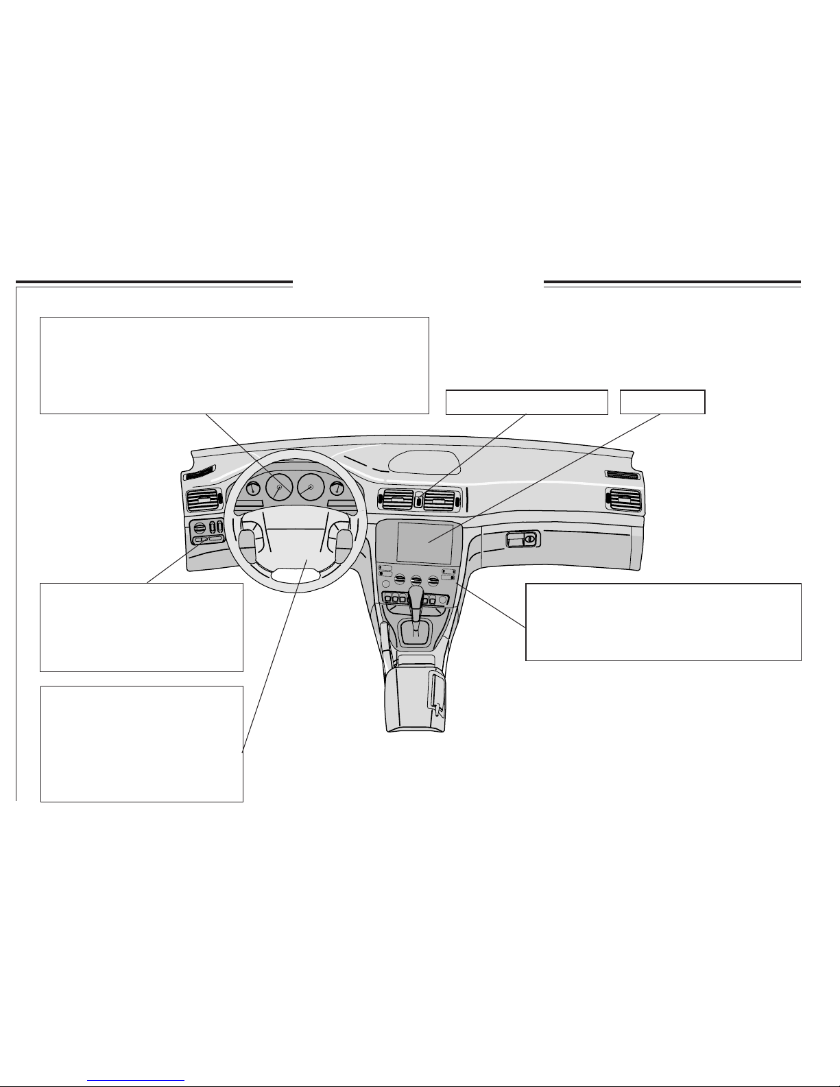
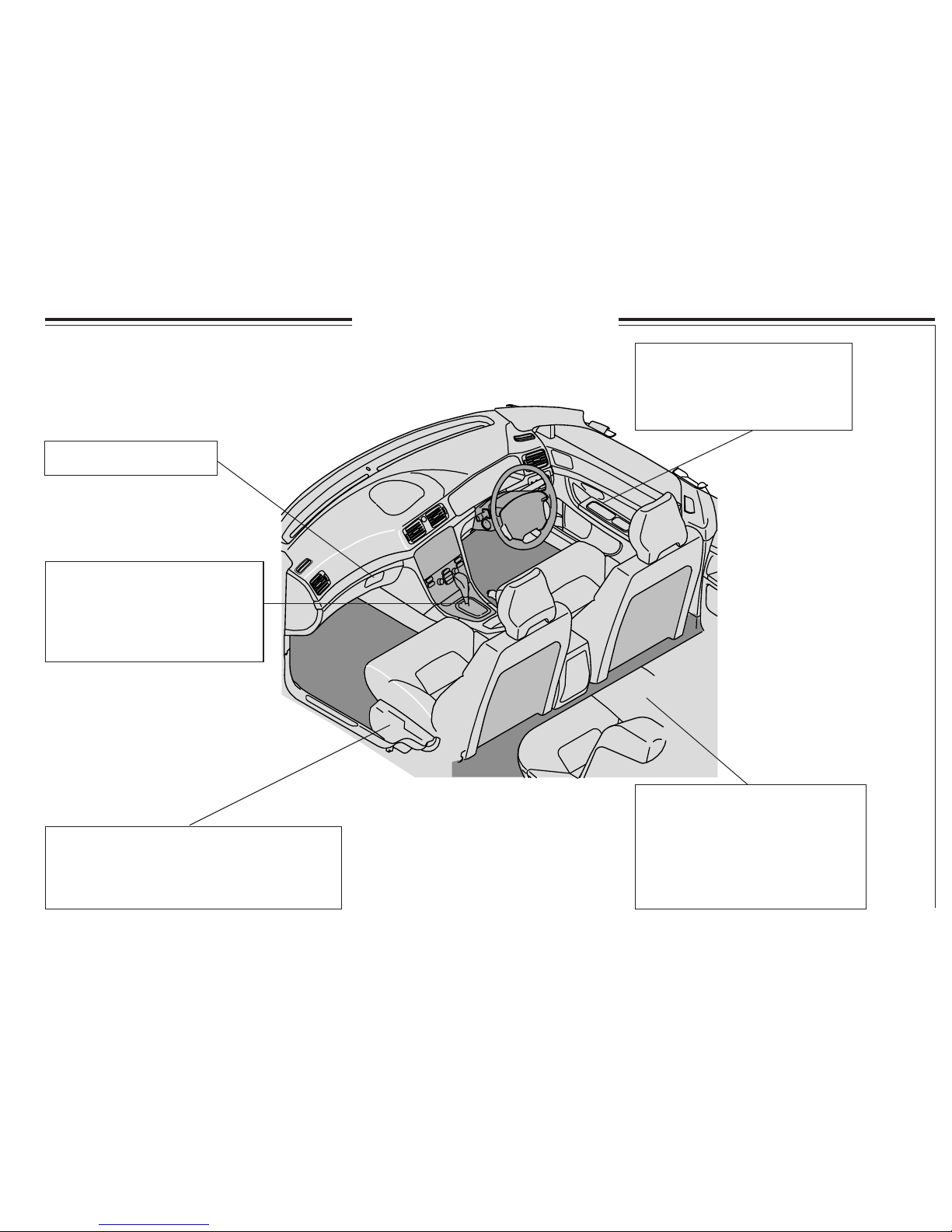
Dashboard - left-hand drive
Display ................................... 30
Tachometer.............................. 26
Automatic gearbox ................. 26
Clock ...................................... 26
Outside temperature sensor .... 26
Fuel gauge .............................. 26
Temperature gauge.................. 26
Speedometer ........................... 26
Odometer ................................ 26
Trip odometer ......................... 26
Warning symbols .................... 27
Main/Dipped beam .................. 35
Position/Parking lamps ............ 35
Fog lamps ................................ 35
Instrument lighting .................. 35
Beam length control ................. 35
Hazard warning flashers....38
Electronic climate control ECC ........................... 48
Manual climate control A/C ................................ 52
Seat heating ......................................................... 38
Defroster - rear window, door mirrors............... 38
Radio ..... 141
Steering wheel adjustment ........ 36
Airbag ......................................... 9
Cruise control ........................... 34
Radio keypad .......................... 147
Windscreen washers/wipers ..... 37
Direction indicator lever ........... 36
Trip computer ........................... 33
Page 5
3
8502061d
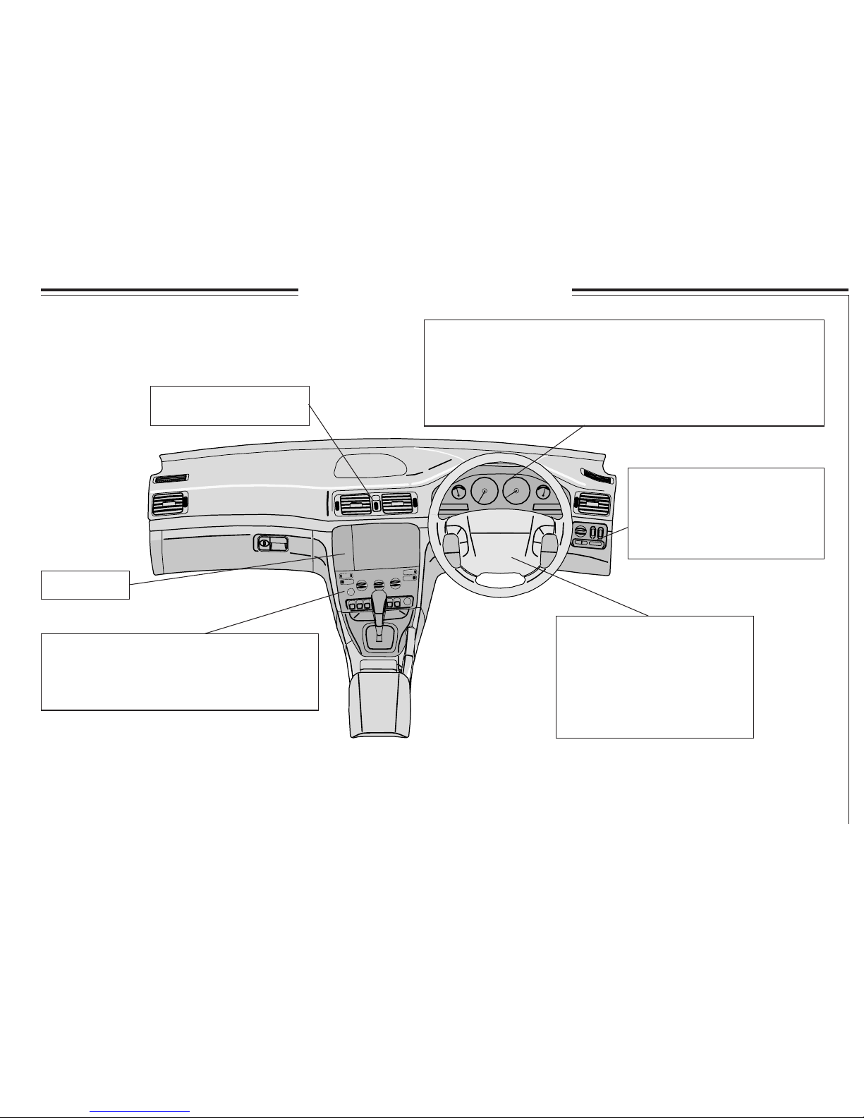
Dashboard - right-hand drive
Radio ..... 141
Main/Dipped beam .................. 35
Position/Parking lamps ............ 35
Fog lamps ................................ 35
Instrument lighting .................. 35
Beam length control ................. 35
Electronic climate control ECC ........................... 48
Manual climate control A/C ................................ 52
Seat heating ......................................................... 38
Defroster - rear window, door mirrors............... 38
Steering wheel adjustment ....... 36
Airbag ........................................ 9
Cruise control .......................... 34
Radio keypad ......................... 147
Windscreen washers/wipers .... 37
Direction indicator lever .......... 36
Trip computer .......................... 33
Display ................................... 30
Tachometer.............................. 26
Automatic gearbox ................. 26
Clock ...................................... 26
Outside temperature sensor .... 26
Fuel gauge .............................. 26
Temperature gauge.................. 26
Speedometer ........................... 26
Odometer ................................ 26
Tripodometer .......................... 26
Warning symbols .................... 27
Hazard warning
flashers ....................... 38
Page 6
4
8502000d
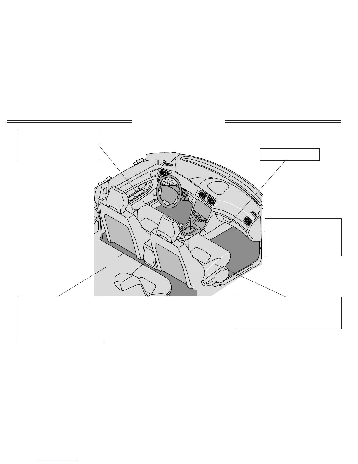
Interior - left-hand drive
Doors and Locks ..................... 68
Alarm ....................................... 73
Power windows ...................... 40
Power mirror controls ............. 41
Manual gearbox .................... 82
Automatic gearbox ............... 83
Geartronic ............................. 85
Handbrake ............................ 39
Switch in centre console ....... 31
Manual adjustment of front seats ............... 58
Electrical adjustment of front seats ............. 60
Seat heating .................................................38
Cleaning the upholstery ............................ 119
Tipping backrests forward .......... 65
Hatch for long loads .................... 65
Tilting head restraints forward .... 31
Adjusting head restraints ............. 59
Child locks ................................... 72
Integrated booster cushion
for children .................................. 22
Glovebox ................ 62
Page 7
5
8502062d
Interior - right hand drive
Glovebox. ............... 62
Manual gearbox .................... 82
Automatic gearbox ............... 83
Geartronic ............................. 85
Handbrake ............................ 39
Switch in centre console ....... 31
Tipping backrests forward .......... 65
Hatch for long loads .................... 65
Tilting head restraints forward .... 31
Adjusting head restraints ............. 59
Child locks ................................... 72
Integrated booster cushion
for children .................................. 22
Manual adjustment of front seats ............... 58
Electrical adjustment of front seats ............. 60
Seat heating ................................................. 38
Cleaning the upholstery ............................ 119
Doors and Locks ..................... 68
Alarm ....................................... 73
Power windows ...................... 40
Power mirror controls ............. 41
Page 8
6
8000233d
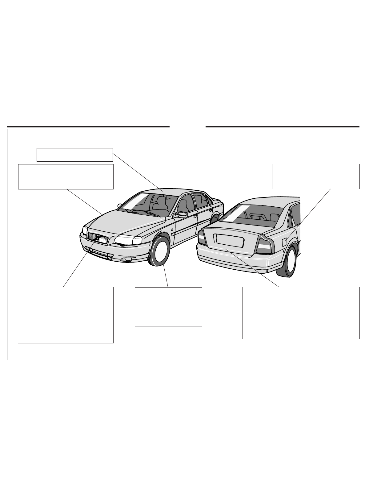
Exterior
Replacing main beam bulb ......... 108
Replacing dipped beam bulb ...... 108
Replacing position lamp bulb ..... 109
Replacing direction indicator lamp
bulb ............................................. 109
Replacing fog lamp bulb ............ 111
Replacing headlamp wiper
blades .......................................... 132
Tyres ........................ 97
Wheels ..................... 97
Brakes ...................... 18
Spare wheel ............. 100
Changing wheels ..... 102
Fuel filler flap ........................... 78
Refuelling ................................. 78
Economical driving ................... 80
Sunroof ........................ 42
Cleaning the car body .............. 118
Rustproofing ............................ 116
Touching up paintwork............ 117
Boot lid .......................................................... 70
Replacing reversing lamp bulb ................... 110
Replacing brake lamp bulb .......................... 110
Replacing tail lamp bulb .............................. 110
Replacing direction indicator lamp bulb ...... 110
Replacing fog lamp bulb ............................. 110
Replacing number plate lighting .................. 112
Page 9

7
Safety
Seat belts 8
SRS (airbag) and SIPS bag (side airbag) 9
SIPS airbag 11
IC system (Inflatable Curtain) 15
WHIPS 16
Brake system 18
Stability system 20
Children in the car 21
Page 10
8
8801947d
Seat belts
Use the seat belt for
all types of driving
Even hard braking can have dangerous
consequences if you are not wearing a seat belt!
Therefore, always ask your passengers to use
seat belts! Otherwise rear seat passengers may
be thrown into the front seat backrests in a
collision, injuring everyone in the car.
Use the seat belt as follows: pull the belt out
slowly and secure it by inserting the locking tab
into the lock. A loud ”click” indicates that the
belt is locked.
The belt is not normally restricted and you
can move freely.
The belt is restricted and cannot be pulled out
further:
· if it is pulled out too fast
· during braking and acceleration
· if the car leans excessively
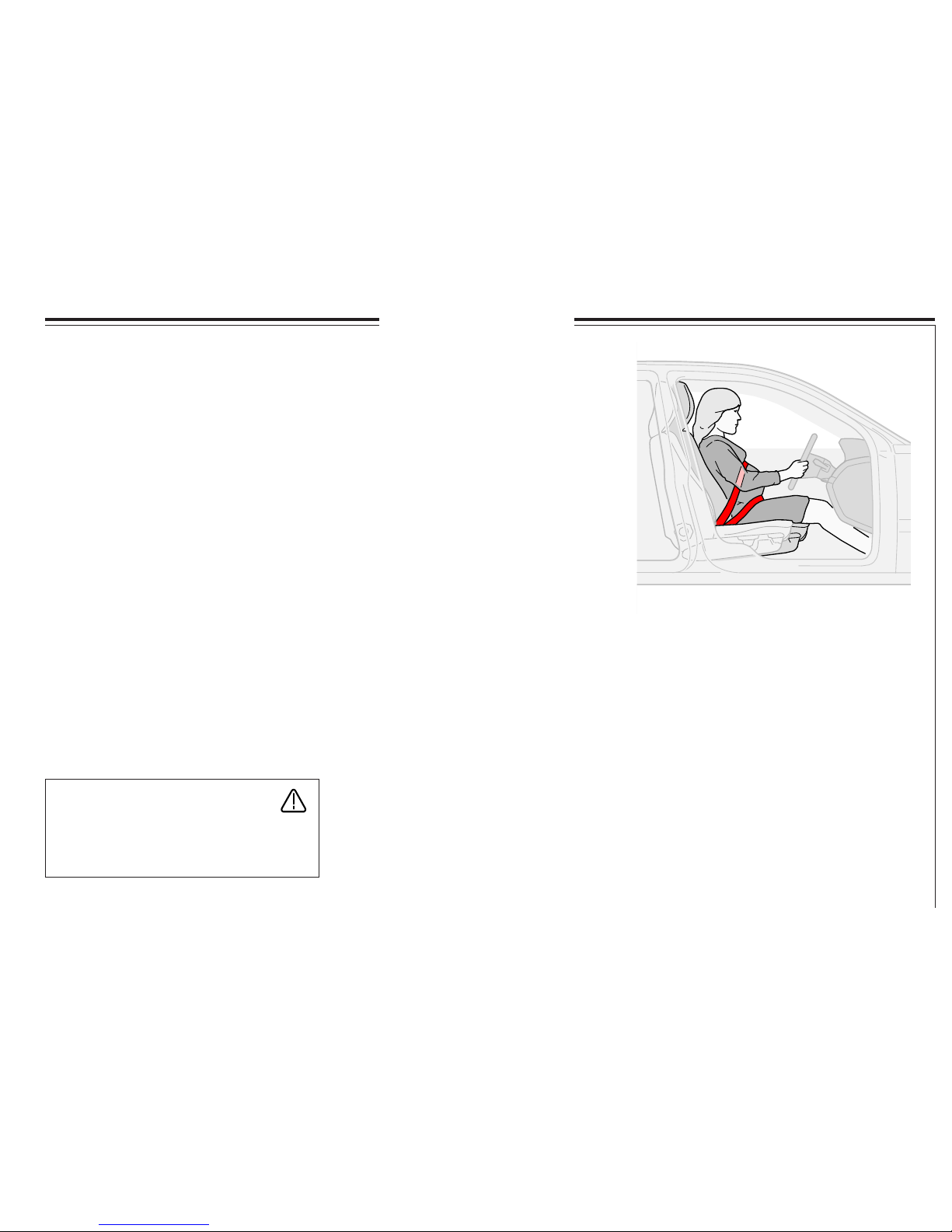
It is important that the belt lies against the body
so it can provide maximum protection. Do not
lean the backrest too far back.
The seat belt is designed to protect in a normal
seating position.
WARNING!
If the seat belt has been exposed to large
load strain, in a collision for example, the
entire seat belt assembly including reel,
mountings, screws, and lock must be
replaced. Even if the belt appears undamaged some of the protective properties may
have been lost. Replace the seat belt if it is
worn or damaged. Never make any
modifications or repairs to the seat belt
yourself; always allow a Volvo workshop
to carry out the work.
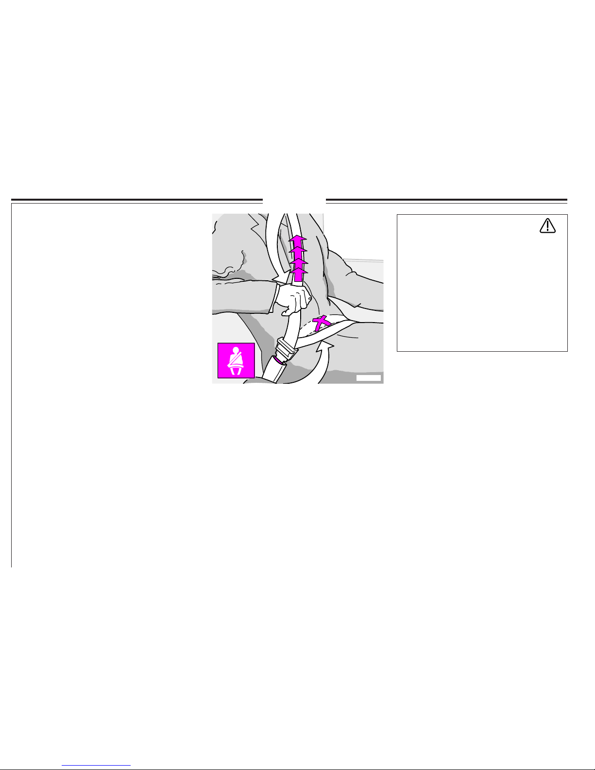
Extending the lap belt
The lap belt should be low
Keep in mind the following:
· do not use clips or anything else that
prevents the belt from lying correctly.
· ensure the belt is not twisted or caught
on anything.
· the lap belt should sit low - not over the
abdomen.
· stretch the lap belt over the lap by pulling
the diagonal shoulder belt as illustrated
above.
Each seat belt is intended for one person only!
To release the seat belt: Press on the red button
in the lock. Allow the reel to pull the belt in.
Page 11
9
8801919d
8802092M
8802099m
8801907e
SRS (airbag) and SIPS bag (side airbag)
WARNING!
Airbags (SRS) are installed as an addition to - not as a replacement
for - the standard seat belts.
The side impact airbags are supplied as an addition to the existing
SIPS* system. For maximum protection: Always wear a seat belt.
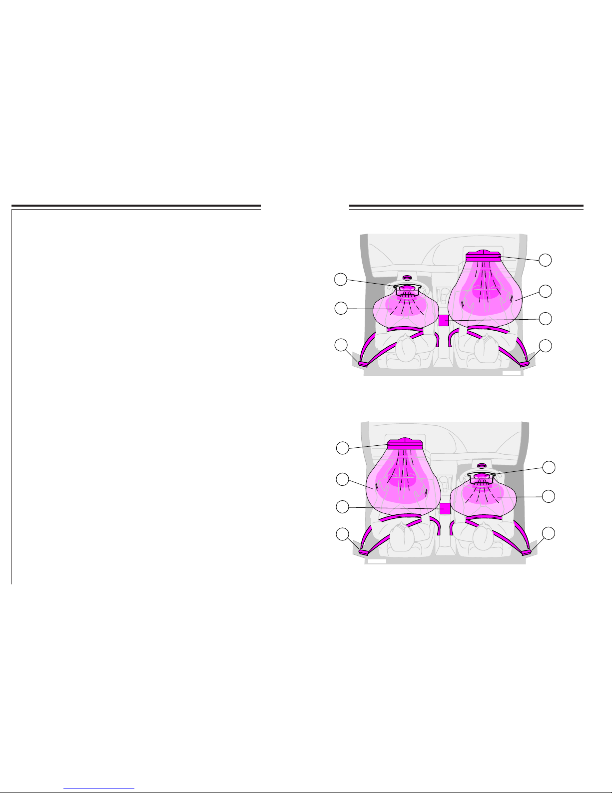
SRS (Airbag) and SIPS bag (side impact airbag)
To further increase interior safety, your car is equipped with airbags (SRS)
to complement the standard three point seat belt The car is marked SRS on
the steering wheel and on the dashboard in front of the passenger, if the
car has a passenger side airbag. The inflatable airbag is installed folded up
in the centre of the steering wheel. On the passenger side it is folded up in
a compartment above the glovebox.
SIPS (side impact airbags) further increase the interior safety of the car.
The side impact airbags are installed in both front seat backrest frames.
*Side Impact Protection System
The side impact airbags are installed in the
front seat backrest frames
The side airbag is above the glovebox,
marked SRS
The airbag is located in the centre of the
steering wheel, marked SRS
Page 12
10
2
4
3
1
4
2
1
8801923d
4
2
1
2
4
3
1
8801896d
SRS (airbag)
SRS system left-hand drive
3. Sensor
4. Seat belt tensioner
1. Gas generator
2. Airbag
SRS system right-hand drive
1. Gas generator
2. Airbag
3. Sensor
4. Seat belt tensioner
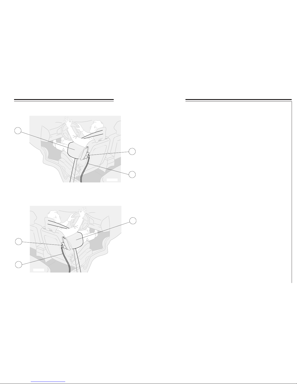
SRS system
(airbags in the steering wheel and dashboard)
The system consists of a gas generator (1) surrounded by the inflatable
airbag (2). Upon a sufficiently violent collision, a sensor (3) reacts,
activating the gas generator igniter, and the airbag inflates as it heats up.
To cushion the impact, the airbag deflates when compressed.
When this occurs, smoke escapes into the car. This is completely normal.
The entire process, including inflation and deflation of the airbag, occurs
in tenths of a second.
NOTE! The sensor (3) reacts differently depending on whether the
driver’s seat belt or front passenger seat belt is used or not.
Crash situations can therefore occur where only one airbag is deployed.
Volvo Dual-Stage Airbag
(Dual-stage airbags)
In the event of lesser collisions, substantial enough to cause injury, the
airbags inflate to slightly more than half their full capacity. In the event of
collisions of greater force, the airbags inflate to their full capacity.
Seat belts and seat belt tensioners
All seat belts are equipped with a pyrotechnic seat belt tensioner (4).
A small charge, integrated into the seat belt reel, ignites at the moment of
impact and tensions the belt over the body so that any slack, caused by
clothing etc., is minimized to restrain the occupant more rapidly. The front
seat seat belt tensioners are only triggered if the seat belt is connected.
Page 13
11
2
8801922d
3
1
1
8801920d
2
3
SIPS bag (side airbag)
SIPS bag system left-hand drive
SIPS bag system right-hand drive
1. Airbag
2. Cable
3. Gas generator
1. Airbag
2. Cable
3. Gas generator
SIPS bag system (side impact airbag)
This system consists of a gas generator (3), electric sensors, cables (2)
and side impact airbags (1). In the event of a sufficiently violent collision
the sensors react, activating the gas generator which inflates the side
airbag. The airbag inflates between the occupant and the door panel,
cushioning the impact at the moment of collision and then deflates. The
side impact airbag only inflates on the side of the collision.
Page 14
12
8801995d
TM
TM
TM
VEHICLE
9430422
FURTHERINFORMATION.
SEEOWNERSMANUALFOR
SPECIFIEDDATEBELOW.
PLACEDACCORDINGTO
SHALLBESERVICEDORRE-
MENTALRESTRAINTSYSTEM
ELEMENTSOFTHESUPPLE-
RELIABILITY,CERTAIN
SYSTEM,SIPSBAGAND
ASUPPLEMENTALRESTRAINT
THISCARISEQUIPPEDWITH
TOPROVIDECONTINUED
INFLATABLECURTAIN,
3800639d
SRS (airbag) and SIPS bag (side airbag)
WARNING!
Never try to repair any part of the SRS or SIPS bag systems yourself.
Any interference can cause malfunction and serious injury and any
work should be carried out by an authorised Volvo workshop.
The year and the month given on the decal on the door pillar/s is the
date when you should contact your Volvo workshop to inspect and if
necessary replace the airbags and seat belt tensioners. If you have any
question concerning either system, contact an authorised Volvo workshop.
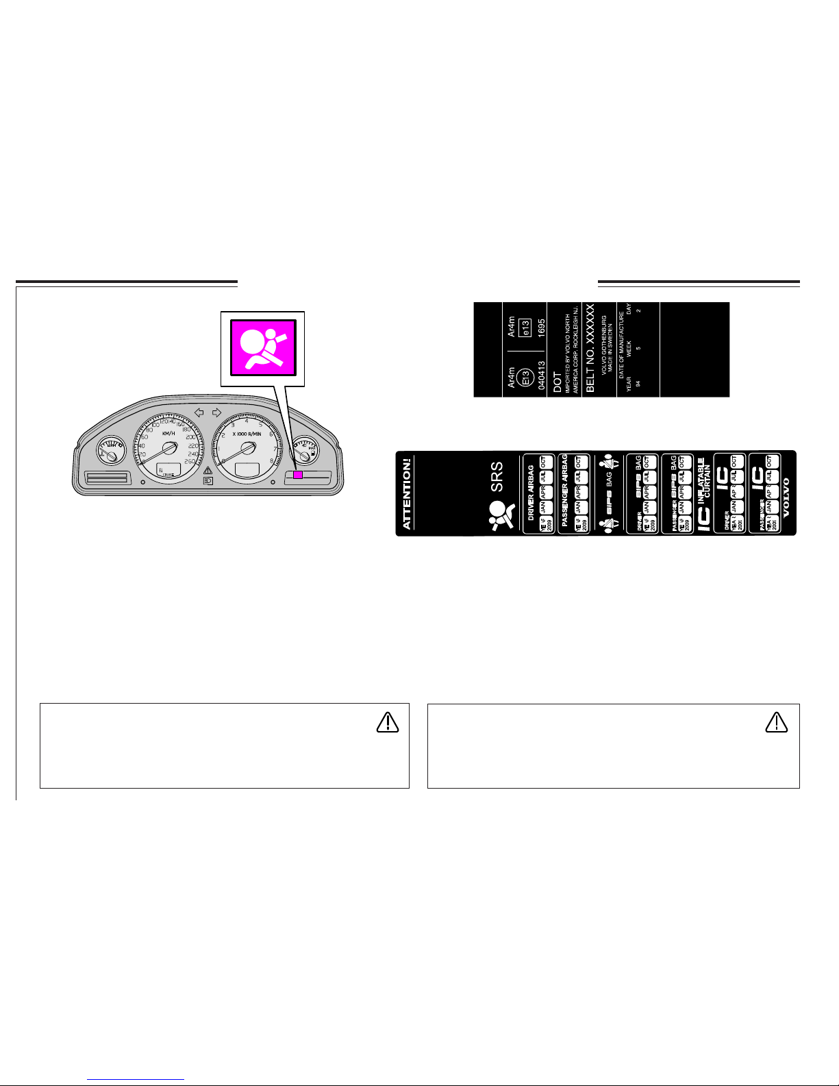
WARNING!
If the warning symbol (SRS) remains lit while driving it means
that the SRS system is not functioning fully. Contact an authorised
Volvo workshop.
This decal is located in the rear left door opening
The SRS system is continuously monitored by the sensor/control module
and there is a warning lamp in the combined instrument panel. This lamp
lights when the ignition key is turned to positions I, II or III. The lamp
goes out when the sensor/control module has checked that the SRS
system is fault-free. This normally takes approximately 7 seconds.
Warning lamp in the combined instrument panel
Marking on seat belts with seat belt tensioners
Page 15
13
8801889e
WARNING!
SIPS airbag
· Extra seat covers must not be used
on the front seats if they are not
Volvo Genuine covers or Volvo
approved seat covers for SIPS airbags.
· No objects or accessories may be
placed between the outer side of the
seat and the door panel because this
area may be affected by the SIPS airbag.
· Never interfere with the SIPS airbag
system.
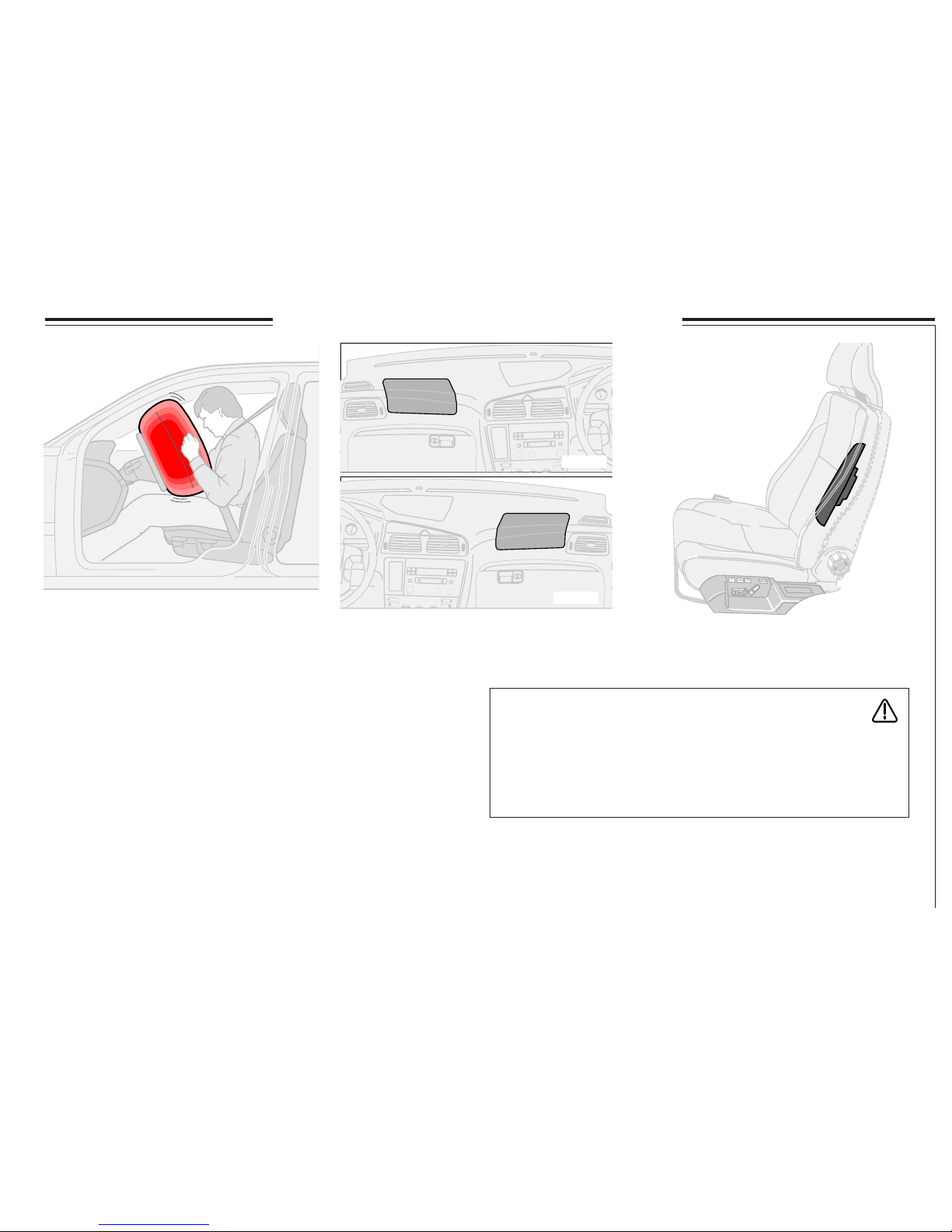
Airbag - passenger side (option)
When the airbag is inflated the volume is
approximately 150 litres on the passenger side,
while the driver's side airbag, because of the
location of the steering wheel, is approximately
65 litres. The crash protection is the same in
both locations.
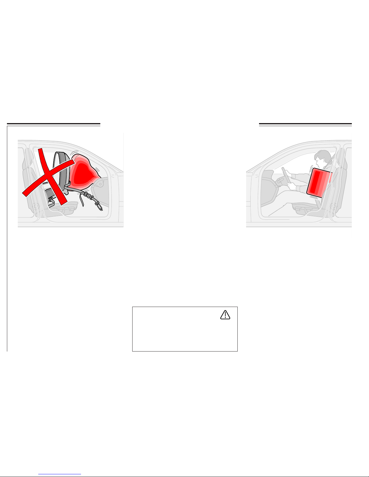
WARNING!
Airbag - passenger side
· The passenger in the front seat should
never sit bent over the dashboard, at the
front of the seat, or in another abnormal
seating position. The passenger should
sit as upright as is possible and
comfortable, back against the backrest.
The seat belt should be under some
tension.
· Ensure that the passengers keep their
feet on the floor (not on the dashboard,
on the seat, in the map and newspaper
compartment, or on the side window).
· Never allow children to sit or stand in
front of the passenger seat.
· Never put a child seat or booster
cushion on the front passenger seat if
the car is equipped with SRS (Airbag)
on the passenger side.
· No one shorter than 140 cm should sit
in the front seat.
· No objects or accessories may be
positioned or stuck on or near the SRS
panel (above the glovebox) or in the
area affected by the airbag.
· Do not place loose objects on the floor,
seat, or on the dashboard.
· Never interfere with the SRS compo-
nents in the steering wheel hub or in the
panel above the glovebox.
SRS (airbag) and SIPS bag (side airbag)
Passenger side airbag deployment
WARNING!
Do not stick or mount your own emblems
or decals on the steering wheel or dashboard!
Page 16
14
8801908e
8801909e
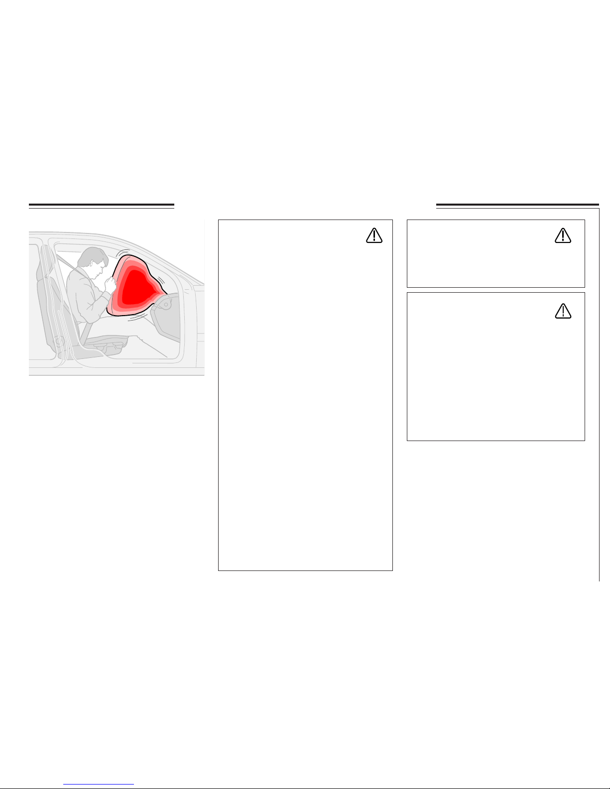
SIPS airbag
The SIPS system is an electrical system,
consisting of two main components: the side
impact airbags and sensors. The side impact
airbags are installed in the front seat backrest
frames and the sensors are in the insides of the
centre and rear pillars. The volume of the
inflated side impact airbags is approximately
12 litres.
The side impact airbag normally inflates only
on the side of the collision.
Inflated SIPS airbag
Child seat and airbag
A child can be seriously injured if a child seat
or booster cushion is used in the front seat of a
car equipped with a passenger side airbag.
The safest place for a child and child
seat/booster cushion is the rear seat, if the
car is equipped with passenger side airbag.
If the car is only equipped with SIPS airbags
child seats/booster cushions can be placed in
the front seat.
Airbags and child seats are not compatible!
WARNING!
Never put a child seat or booster cushion
on the front passenger seat if the car is
equipped with SRS (Airbag) on the
passenger side.
Never allow a child to sit in the front passenger
seat if your car is equipped with an SRS
(Airbag) on the passenger side (child refers to
any person whose height is 140 cm or less).
Place the child instead in a child seat or on a
booster cushion in the backseat.
SRS (airbag) and SIPS bag (side airbag)
Page 17
15
8801966e
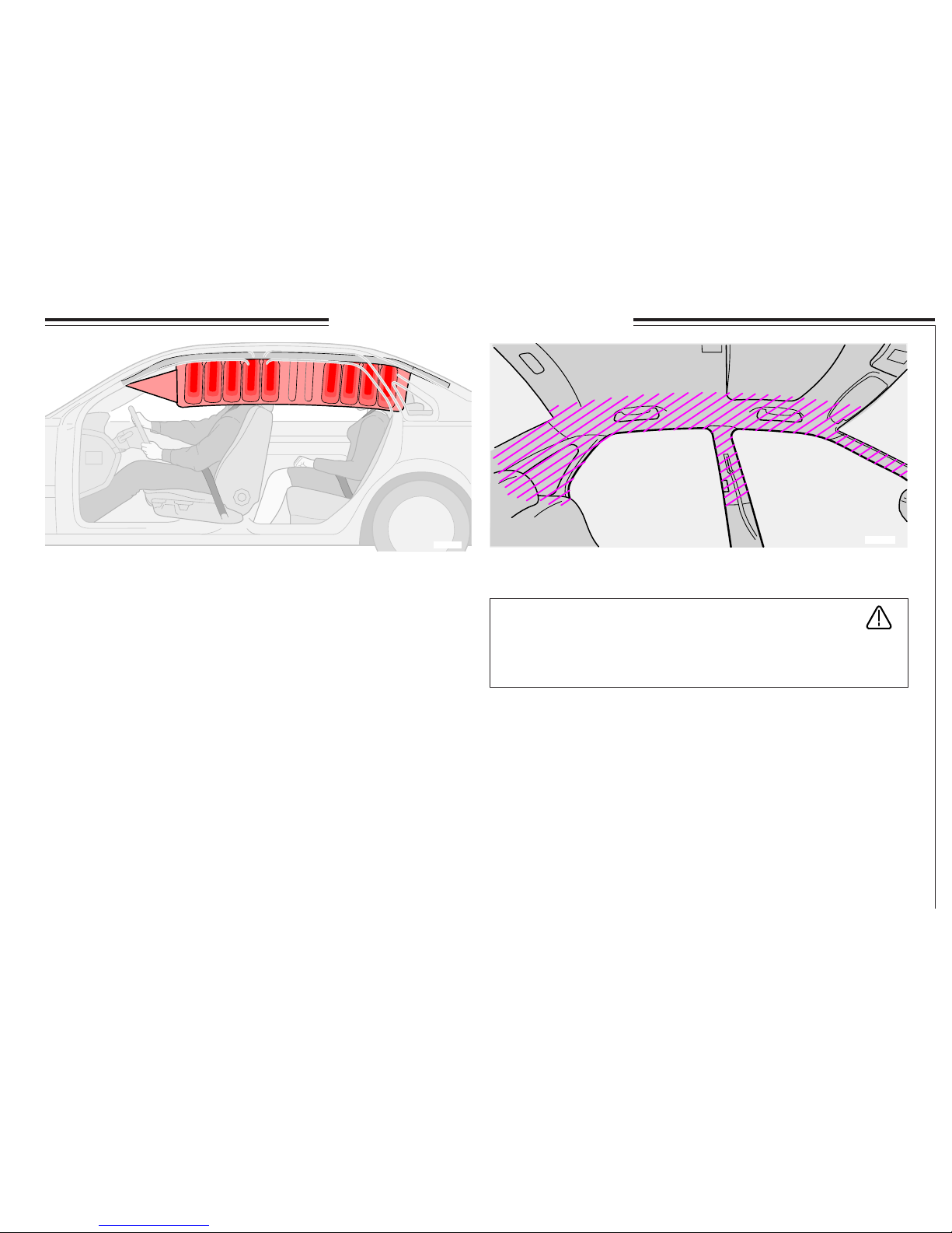
IC system (Inflatable Curtain)
8801999d
IC system (Inflatable Curtains)
The IC system protects the head from blows against the car interior. The
curtain also protects against objects that the car is in collision with. The IC
system protects both those travelling in the front and outer rear seats. The
curtain is hidden inside the headlining. The IC system - inflatable curtains
- covers the upper part of the car interior next to the front and rear seats.
The IC system is activated by the SIPS system collision sensors, when
the car is hit from the side. When the IC system is activated the curtain is
filled with gas from the gas generator, which is located in the rear end of
the curtain.
Always use the safety belts!
If you have passengers in the rear seat, ensure that the rear seat head
restraints are folded up and that the centre head restraint is correctly
adjusted for a passenger.
WARNING!
Do not screw or mount anything to the headlining, door pillars
or side panels. The intended protection may be compromised.
Page 18
16
8502379e
8502213e
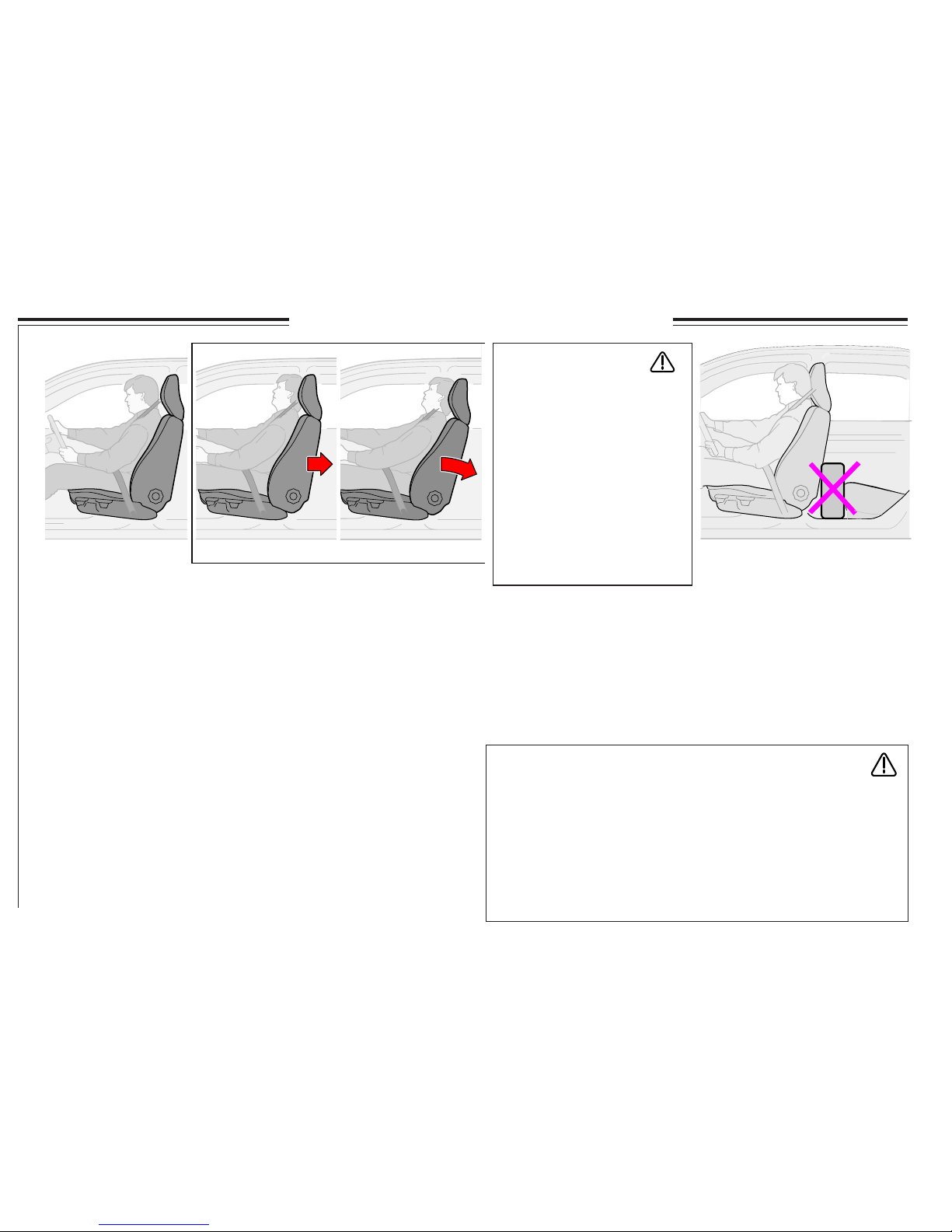
WHIPS (Whiplash Protection System)
WHIPS
This system consists of energy absorbing backrests and specially
developed head restraints in both front seats.
WHIPS seat
WHIPS is activated in event of a collision from behind, based on the
collision angle, speed and nature of the colliding vehicle. Upon activation
the backrests of the front seats, if occupied, move backwards and the
seating position of the occupants in the front seats is altered. This
diminishes the risk of whiplash injury.
Correct seating position
For the best possible protection, you and your front seat passenger
should sit in the centre of your seats with as little distance as possible
between the head restraints and your heads.
WARNING!
If the seat has been exposed to a heavy load strain, for example a
collision, the WHIPS system should be inspected at an authorised
workshop. Even if the seat does not appear damaged, the WHIPS
system may have deployed without causing visible damage to the seat.
Parts of the WHIPS protective capacity may have been lost. Allow an
authorised Volvo workshop to check the system even after minor
collision from behind. Never modify or repair the seat or the WHIPS
system yourself!
WHIPS and child seat
The WHIPS system does not negatively affect the protective properties of
the car as regards Volvo child seats. As long as there is no passenger side
airbag (SRS), a child seat may be placed on the front passenger seat. The
WHIPS system stills functions if a rear-facing child seat is placed on the
rear seat with the support against the front seat backrest.
WARNING!
Never obstruct WHIPS system functions!
· If a rear backrest has been
lowered, adjust the corresponding front seat in order to
avoid contact with the lowered
backrest.
· Avoid placing boxes or similar cargo so that they are
clamped between the rear seat
cushion and the front seat
backrest.
Page 19
17
WARNING!
Never drive with deployed airbags! They can hinder the steering
of your car. Other safety systems may also be damaged. Intensive
exposure to the smoke and dust released when the airbags are
deployed can cause eye and skin irritation. If irritated, wash with
cold water and/or contact a doctor. The speed of deployment can, in
conjunction with the airbag fabric, cause friction burns to the skin.
SRS (airbag), SIPS bag (side airbag) and Inflatable Curtain (IC)
When do the airbags and curtains inflate?
The SRS system senses the collision in the level of braking and the speed
reduction caused by the collision. The sensor determines whether the
collision is of the character and nature requiring the airbag deployment.
Note that it is not only the deformation of the bodywork which affects
the car’s sensors but also the speed reduction at the moment of impact.
This means that the SRS sensor senses those occasions when there is a
risk that occupants in the front seats may be injured by blows against the
dashboard or steering wheel.
The above applies to the SIPS system (side airbags), and inflatable
curtains except that side impact airbags and inflatable curtains are only
deployed in side-on collisions, when the car is hit by an object with
sufficient force.
NOTE! Deployment of the SRS, SIPS and IC systems occurs only once
in a collision in the relevant direction.
If the airbags have been deployed, we recommend the following:
· Tow the car to a Volvo workshop. Do not drive the car with the
airbags deployed even if the car can be driven after an accident.
· Let an authorised Volvo workshop replace components to the SRS,
SIPS, and IC systems.
WARNING!
The SRS sensors are located in the centre console. If the passenger
compartment floor has been drenched with water, remove the
battery leads in the cargo compartment. Do not try to start the car;
the airbags may deploy. Tow the car to an authorised Volvo
workshop.
Page 20
18
ABS - Anti-lock brakes
The ABS system (Anti-lock Braking System) is
designed so that the wheels do not lock when
braking. This retains the best possible steering
response when braking. This improves your
ability to swerve to avoid obstacles. The ABS
system does not increase your total braking
capacity. However, as the driver you have
increased ability to steer and thus better control
over the car, which in turn increases safety.
After the engine has started and reached a speed
of about 20 km/h (12 mph), a short self-test can
be both heard and felt. When the ABS system
functions, you can hear and feel pulses in the
brake pedal. This is completely normal.
If a brake circuit fails
If a fault should occur in one of the circuits it is
still possible to stop the car. Press the pedal
hard once - not repeatedly. The brake pedal can
be depressed further and feels a little softer than
usual. If also requires more pressure on the
pedal to achieve a normal braking effect.
The brake servo only works when the
engine is running
If the car is rolling or being towed with the
engine switched off you must apply approximately five times more pressure on the brake pedal
than when the engine is running.
The brake pedal feels rigid and hard.
Moisture on the brake discs and brake
lining alter braking characteristics!
The brake components become wet when the
car is driven in heavy rain, through pools of
water, or when the car is washed. This alters
brake pad friction characteristics so that there is
a delay before braking effect is noticed. Depress
the brake pedal lightly from time to time when
driving long distances in rain or slush or before
parking the car in such conditions. The brake
pads are thus able to warm up and dry out. You
should also do this when driving after washing
the car or when starting in very damp or cold
weather conditions.
If the brakes are heavily loaded
When driving in the Alps or other roads with
similar characteristics, the brakes are heavily
loaded even if you are not pressing the pedal
particularly hard. Because the speed is often
low the brakes are not cooled as effectively as
when driving on flat roads.
So as not to overload the brakes shift down
and use the same gear both uphill and downhill
instead of using the brake (manual transmission). In this way engine braking is used more
effectively and the brake is only required for
short periods.
Keep in mind that the brakes are even more
heavily loaded when driving with a trailer.
Brake system/ABS/EBD
NOTE! You must depress the brake pedal fully
to take maximum advantage of the ABS system.
Do not release the pedal when the ABS pulses
are felt and heard. Practice braking with the
ABS system in a suitable place.
The ABS symbol islights and shines with a
constant glow:
· For approximately two seconds when you
start the car to test the system.
· If the ABS system has shut down due to a
fault.
Electronic Brakeforce
Distribution (EBD)
The EBD system (Electronic Brakeforce
Distribution) is an integrated part of the ABS
system. The EBD system controls the brake
force to the rear wheels so that the best possible
braking force is always available. Pulses in the
brake pedal can be felt and heard as the system
controls the brake force.
WARNING!
If both the BRAKE and ABS
warning symbols are lit, there is a risk
that the rear end will have a tendency to
slide during heavy braking. If the brake
fluid reservoir level is normal in these
circumstances, you may, very carefully,
drive the car to the nearest authorised
Volvo workshop to have the brake
system checked.
Page 21

19
Stability system
Stability and Traction
Control STC/DSTC*
The STC system (Stability and Traction
Control) contains the functions TC and SC.
The DSTC system (Dynamic Stability and
Traction Control) contains the functions TC,
SC, AYC and EBA
Traction Control -TC
The traction control transfers the motive power
from a drive wheel that spins on the road
surface to the drive wheel that does not spin by
braking the wheel that starts to spin. In order to
increase accessibility in this situation you may
need to press the accelerator harder than usual.
A pulsing sound can be heard when traction
control is working. This is completely normal
for the system. The TC function is mostly
active at low speeds. It cannot be deactivated.
Stability Control - SC
Stability Control is designed to prevent the
drive wheels spinning on the road surface
during acceleration, by lowering the engine
torque on the drive wheels. This improves
accessibility and road safety in slippery road
conditions. In specific conditions, for example,
driving with snow chains, in deep snow or
sand, it can be beneficial to deactivate the SC
function to increase traction. This is then done
using the DSTC button.
Active Yaw Control - AYC
The anti-skid function performs automatic
braking on one or more of the car's wheels.
This stabilises the car if it starts to skid. If in
this situation you attempt to apply the brakes
yourself, the brake pedal will feel harder than
normal and a pulsing sound will be heard. The
AYC function is active the whole time and, for
reasons of safety, it cannot be deactivated.
Emergency Brake Assistance (EBA)
The EBA function is an integrated part of the
DSTC system. The system is designed to
provide full braking force immediately when
rapid braking is necessary. The system senses
when you need to brake heavily by registering
how quickly you press down the brake pedal.
The EBA function is active at all speeds and,
for reasons of safety, cannot be deactivated.
NOTE! When the EBA function is active the
brake pedal sinks at the same time as the car has
maximum brake force available. Continue
applying the brakes without releasing the
pressure on the brake pedal. The EBA function
disengages when the pressure on the brake
pedal is eased.
STC/DSTC button
The STC/DSTC button in the centre console is
used to reduce or reactivate the STC/DSTC
system.
When the LED in the button comes on the
STC/DSTC system is activated (if no fault
arises).
When reduced the stability control (SC) is
deactivated and the active yaw control (AYC) is
reduced. Other functions are not affected.
NOTE! In order to reduce the effect of the STC/
DSTC system for reasons of safety the button
must be held in for at least a half second.
The LED in the button goes out and the display
shows: "STC SPIN CONTROL OFF"/
DSTC SPIN CONTROL OFF".
The STC/DSTC system is automatically
activated each time the engine is started.
The warning symbol
flashes when...
· ...the SC function works to prevent the car's
drive wheel from spinning.
· ...the TC function works to improve the car's
traction.
· ...the AYC function works to prevent the car
from skidding.
The warning symbol
comes on and goes
off after approximately 2 seconds when ...
· ...the car starts. (The lamp comes for a system
check.)* The STC and DSTC system is an option on
some markets
Page 22
20
Stability system
WARNING!
In normal driving conditions the STC/
DSTC system improves the car's road
safety, which should not be perceived as a
possibility to increase speed. Always follow
the usual precautions to ensure safe
cornering and driving on slippery surfaces.
Remember the driving characteristics of the
car change if you deactivate the STC/DSTC
system.
The LED in the button goes out and the text
"STC SPIN CONTROL OFF/DSTC SPIN
CONTROL OFF" is shown on the display
when...
· ...the STC/DSTC system's SC function has
been reduced using the DSTC button.
The warning symbol
lights yellow and
the text "TRACTION CONTROL TEMPORARILY OFF " is shown on the display
when...
· ...the brake system's TC function has been
temporarily reduced due to a high brake
temperature. The TC function is automatically
reactivated when the brake temperature has
returned to normal.
The warning symbol
lights yellow and the
text "ANTI-SKID SERVICE REQUIRED"
is displayed when:
· ...the DSTC system is deactivated due to
a fault.
Road Friction Detection (RFD)
system (option)
Road Friction Detection is an advanced system
which discerns the amount of friction between
the tyres and the road.
The system is designed as an early warning
system which alerts the driver when road
conditions are slippery.
The RFD system is active at low speed and
upwards and cannot be switched off for
reasons of safety.
The warning symbol
lights when:
The RFD system detects low road surface
friction.
The warning symbol
lights with a
fixed, yellow glow and the additional text
"RFD SERVICE REQUIRED" when:
The RFD system has been switched off
due to a fault.
Page 23
21
8801888e
Children should sit
comfortably and safely
Remember that children, regardless of age or
size, should always be securely strapped into
the car. Never allow a child to sit on the knee of
a passenger!
Location and equipment must be selected
with regard to the weight of the child.
Volvo’s own child safety equipment is designed
for your car. If you select Volvo equipment, you
can be sure that the mounting points and
attachments are correctly positioned and
sufficiently strong.
The smallest children should sit in rear-facing
seats. These give children up to the age of
3 - 4 years maximum protection.
NOTE! Many countries have statutory
requirements covering where the child may be
located in the car. Find out what rules apply in
the countries you will be visiting.
Important tips!
When using other child safety products
available on the market it is important that the
installation instructions are carefully read and
closely followed.
These are some points that you should consider:
· The child seat should always be located
according to the manufacturer’s description.
· Do not attach the child seat straps to the seat
springs, rails or any of the rails and struts
under the seat which may have sharp edges.
· Providing that the car is not equipped with a
passenger side airbag (SRS), position the
child seat backrest so that it rests against the
dashboard.
· Do not allow the top portion of the child seat
to rest against the windscreen.
NOTE! If you have difficulties installing a child
safety product contact the manufacturer for
clearer installation instructions.
The lap belt should be low
Pregnant women
Pregnant women should be extra careful when
using seat belts! Always remember to position
the seat belt so that there is no unnecessary
pressure on the womb. The lap belt on the three
point seat belt should be low.
WARNING!
Never put a child seat/booster cushion in
the front seat if the car is equipped with
SRS (airbag) on the passenger side.
Children in the car
Page 24
22
8503186m
8801954d
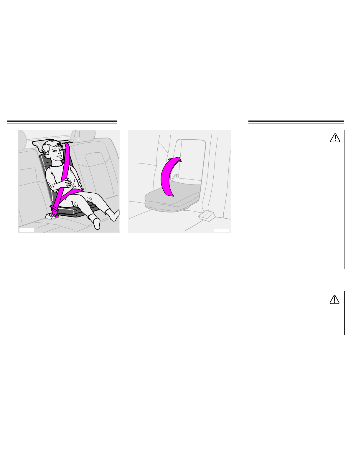
Raising the booster cushion
Raise the booster cushion. The booster cushion
locks automatically in the backrest.
NOTE! See also the directions on the
booster cushion.
WARNING!
The regular armrest in the rear seat must not
be used as a booster cushion. Only Volvo’s
integrated booster cushion may
be used for this purpose.
WARNING!
If the integrated booster cushion has been
exposed to heavy load, in a collision for
example, the entire booster cushion,
including the seat belt and screws, must be
replaced. Even if the integrated booster
cushion appears undamaged some of the
protective properties may have been lost.
The booster cushion should also be
replaced if it is very worn or damaged.
Note that cushion replacement must be
carried out professionally, because it is
important for passenger saftey that the
cushion is correctly installed. Therefore the
replacement and any repairs should be
referred to your Volvo workshop. If the
cushion becomes dirty it should initially be
cleaned in situ. If the cushion is so dirty
that it requires separate cleaning, the above
instructions for replacing and installing the
cushion should be followed.
Booster cushion
Volvo’s integrated booster cushion for the
centre rear seat is specially designed to provide
optimum safety. When used with the regular
three-point seat belt, the booster cushion is
approved for children weighing between
15 and 36 kg.
When a child uses the booster cushion, the lap
belt must be positioned low across the hips not over the stomach.
Carefully adjust the position of the head
restraint to suit the child.
Integrated booster cushion for children
between 15-36 kg
Volvo’s integrated booster cushion
Page 25
23
8802408m
8802355m
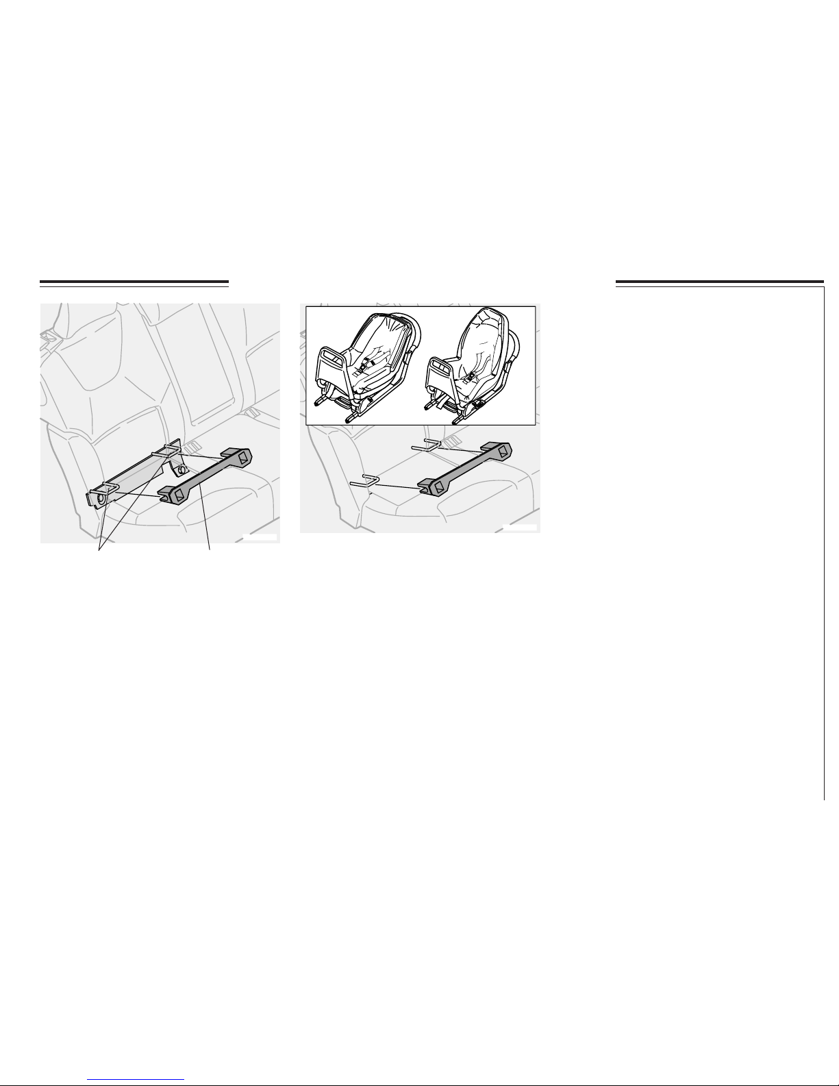
Isofix bracket system for child seats (option)
Isofix bracket system
for child seats
The car can be equipped with an Isofix bracket
system for child seats in the outer rear seats.
Contact your Volvo dealer for further information on child safety equipment.
Isofix attachment points Rail
NOTE! Isofix attachment points are located on
both outer rear seats. The rail can be moved
from one side to the other as needed.
Page 26
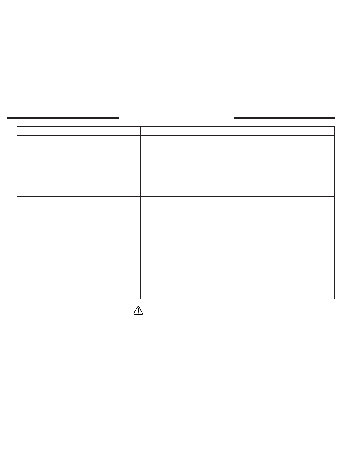
24
Location of the child in the car
*) WARNING!
NEVER place a child seat or booster cushion in the front
seat if the car is equipped with a passenger side airbag.
Weight / Age Front seat, alternatives*
Centre rear seat, alternatives
Outer rear seats, alternatives
<10 kg
(0-9 months)
9-18 kg
(9-36 months)
15-36 kg
(3-12 years)
1. Rear-facing child seat, secured with
seatbelt.
L: Type approval no. E5 03160
2. Rear-facing child seat, secured in
ISOFIX attachment.
L: Type approval no. E5 03162
3. Rear-facing child seat, secured with
seatbelt and mounting strap.
L: Type approval no. E5 03135
1. Rear-facing child seat, secured with
seatbelt and support arm.
L: Type approval no. E5 03160
2. Rear-facing child seat, secured in ISOFIX attachment and with support arm.
L: Type approval no. E5 03162
3. Rear-facing child seat, secured with
seatbelt, support arm and securing strap.
L: Type approval no. E5 03135
1. Rear-facing child seat, secured with
seatbelt.
L: Type approval no. E5 03161
2. Rear-facing child seat, secured in
ISOFIX attachment.
L: Type approval no. E5 03163
3. Rear-facing child seat, secured with
seatbelt and mounting strap.
L: Type approval no. E5 03135
1. Rear-facing child seat, secured with
seatbelt and support arm.
L: Type approval no. E5 03161
2. Rear-facing child seat, secured in
ISOFIX attachment and with support
arm.
L: Type approval no. E5 03163
3. Rear-facing child seat, secured with seatbelt, support arm and securing strap.
L: Type approval no. E5 03135
1. Rear-facing child seat, secured with
seatbelt, support arm and securing
strap.
L: Type approval no. E5 03135
1. Rear-facing child seat, secured with
seatbelt, support arm and securing
strap.
L: Type approval no. E5 03135
1. Booster cushion with or without
backrest.
L: Type approval no. E5 03139
1. Booster cushion with or without
backrest.
L: Type approval no. E5 03139
2. Integrated booster cushion.
B: Type approval no. E5 03140
L: Suitable for certain child seats, as listed. The child seats may be vehicle-specific,
limited, half universal or universal.
B: Integrated and approved for this age group.
Not a suitable placement for this age
group.
Page 27

25
Combined instrument panel 26
Indicator and warning symbols 27
Messages in the display 30
Switches in the centre console 31
Trip computer 33
Cruise control 34
Headlamp, Fog lamps 35
Beam length control, Instrument lighting 35
Direction indicators, Follow-me-home
Steering wheel adjustment 36
Ignition and steering wheel lock, Windscreen washer/wipers 37
Hazard warning flashers, Rear defroster, Heated seats 38
Parking brake, Electrical socket 39
Power windows 40
Rearview mirror/door mirrors 41
Power sunroof 42
Sun blinds, Laminated side windows 43
Instruments, switches and controls
Page 28
26
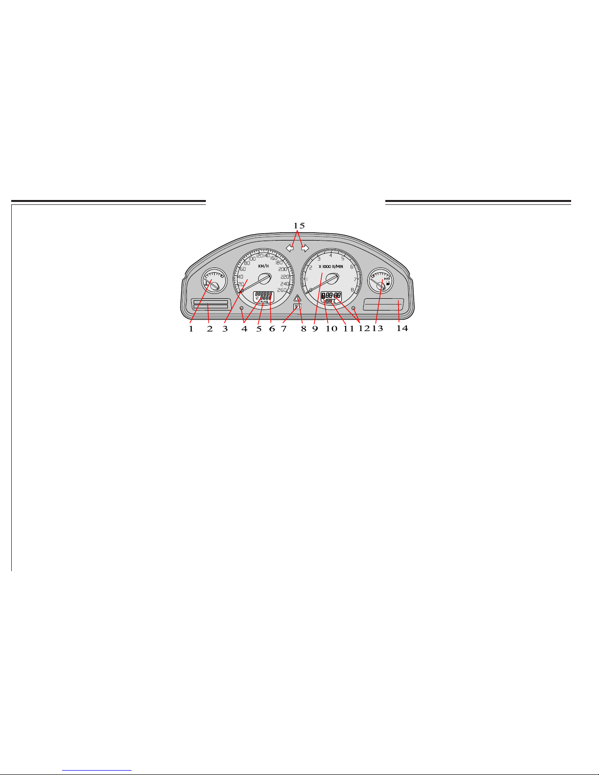
Combined instrument panel
1. Temperature gauge
Displays the engine cooling system temperature. If the temperature is abnormally high and the
needle enters the red field a message is shown
in the display. Remember that extra lamps in
front of the radiator grille reduce the cooling
capacity with high outside temperatures and
high engine loads.
2. Display
The display shows information and warning
messages.
3. Speedometer
Shows the speed of the car.
4. Trip odometer
The trip odometer is used for measuring shorter
distances. The right hand digit gives 100 meter
units. Depress the button for more than
2 seconds to reset. Change between the trip
odometers using one short press on the button.
5. Cruise control indicator
See page 34.
6. Odometer
The odometer indicates the total mileage of the car.
7. Main beam on/off
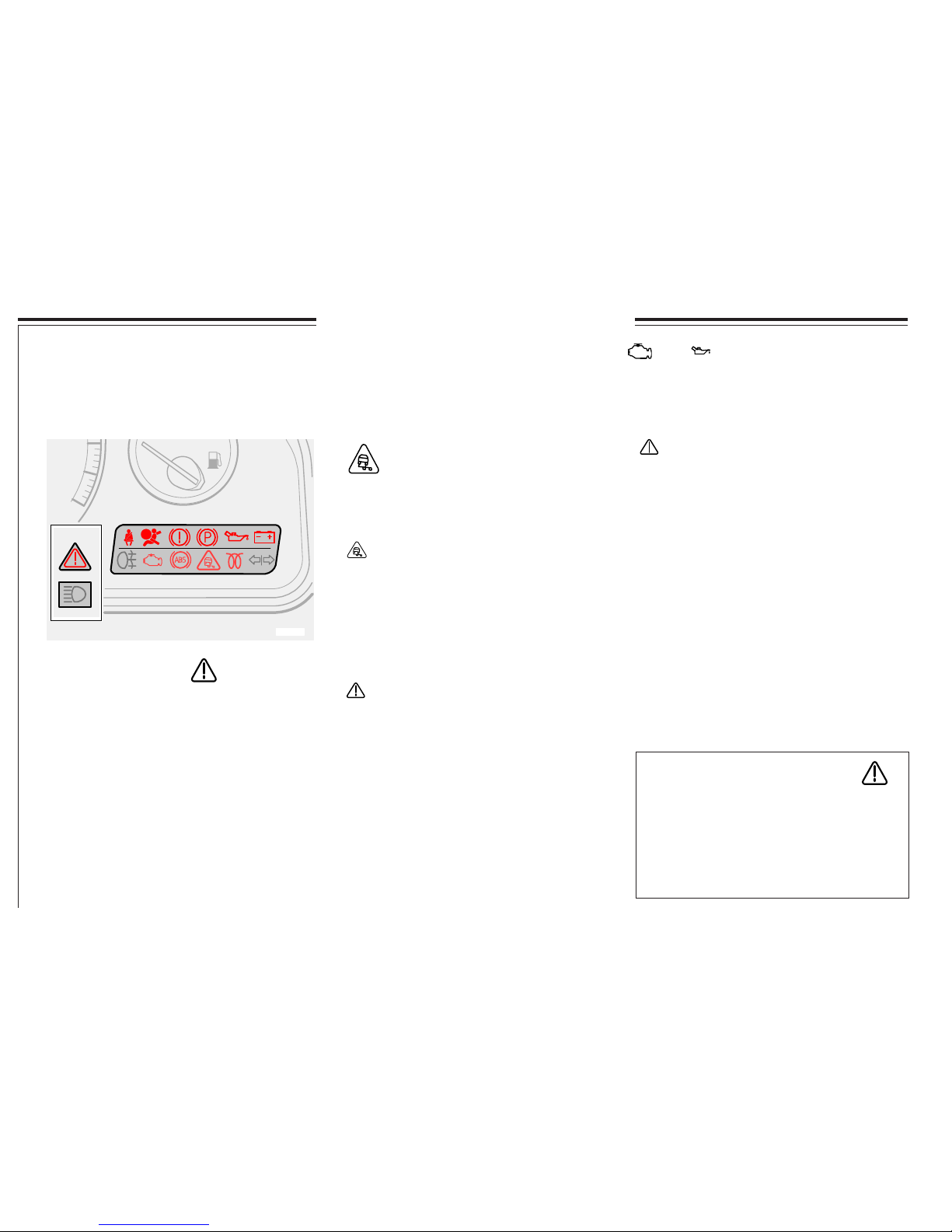
8. Warning symbol
If a fault should occur, the symbol lights and a
message is shown in the display.
9. Tachometer
Gives engine speed in thousands of revolutions
per minute (RPM). The needle on the tachometer
must not enter the red field.
10. Automatic gearbox indicator
The selected gearshift programme is displayed
here. If you have Geartronic automatic transmission and drive in manual mode, the current
manual gear is displayed.
11. Outside temperature gauge
Displays the outside temperature. When the
temperature lies between +2°C and -5°C, a
snowflake symbol is shown in the display. The
symbol warns of slippery road conditions.
When the car is or was stationary, the outside
temperature gauge may rend a higher reading
than is actual.
12. Clock
Turn the button to set the time.
13. Fuel gauge
The fuel tank holds 70/80 litres*. The instrument lights up when approx. 8 litres of usable
fuel remain.
14. Indicator and warning symbols
15. Direction indicators - left - right
*Cars with 6-cylinder engines and all turbo
models come with an 80 litre tank.
3800838m
Page 29
27
3800839m
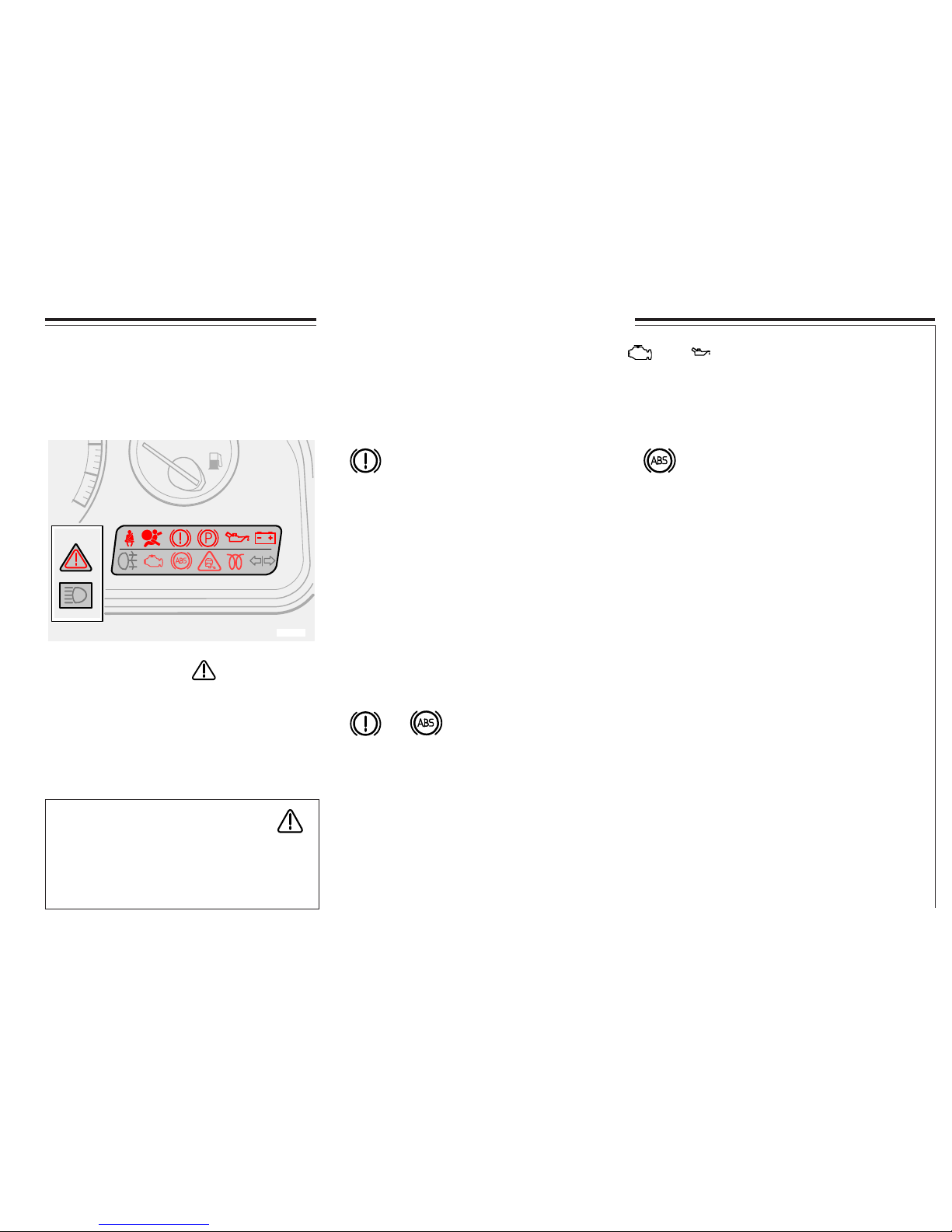
Indicator and warning symbols
WARNING!
If both the BRAKE and ABS warning
symbols are lit up there is a risk that the rear
end will have a tendency to slide during
heavy braking.
Warning - fault in brake system
If the BRAKE symbol lights up the
brake fluid level may be too low.
· Stop the car in a safe place and check the
brake fluid reservoir level.
· If the reservoir level is below MIN the car
should not be driven further. Have it towed
to an authorised Volvo workshop to check
the brake system.
Warning - fault in ABS system
If the ABS warning symbol lights up
the ABS system is not functioning.
The car’s normal braking system continues to
function normally but without the ABS
function.
· Stop the car in a safe place and switch off
the engine.
· Start the engine again.
· If the warning symbol goes out, the fault
was temporary and it is not necessary to
visit a workshop.
· If the warning symbol remains lit, drive
carefully to an authorised workshop to
check the ABS system.
Warning symbol in centre of
dashboard
This symbol shines as an red or yellow light
depending on the severity of the fault discovered. See next page for more information!
The indicator and warning symbols light when the ignition key is
turned to driving position (position II) before starting. This shows
that the symbols are functioning. When the engine is started all the
symbols go out. If the engine is not started within 5 seconds all the
symbols go out except
and . Certain symbols may not
have the function indicated, depending on car equipment. The
symbol for the parking brake goes out when the parking brake is
released.
If BRAKE and ABS warning symbols light up at the same time, there may be
a problem in the brake force distribution.
· Stop the car in a safe place and switch off the engine.
· Start the car again.
· If both warning symbols go out the fault was temporary and it is not necessary to visit a
workshop.
· If the warning symbols remain lit, check the brake fluid reservoir level first.
· If the reservoir level is below MIN the car should not be driven further. Have it towed to an
authorised Volvo workshop to check the brake system.
· If the brake fluid level is normal and the lamps remain lit, carefully drive the car to the nearest
authorised Volvo workshop to have the brake system checked.
Page 30
28
Warning symbol in centre
of dashboard
This symbol shines as an red or yellow light
depending on the severity of the fault
discovered.
Red symbol - Stop the car. Read warning
message in display.
Yellow symbol - Read the message in the
display. Remedy!
3800839m
WARNING!
Under normal driving conditions, the STC/
DSTC system improves the car’s road safety,
but this should not be taken as a reason to
increase speed. Always follow the usual
precautions for safe cornering and driving on
slippery surfaces.
Indicator and warning symbols
The indicator and warning symbols light when the ignition key is
turned to driving position (position II) before starting. This shows
that the symbols are functioning. When the engine is started all the
symbols go out. If the engine is not started within 5 seconds all the
symbols go out except and . Certain symbols may not
have the function indicated, depending on car equipment. The
symbol for the parking brake goes out when the parking brake is
released.
Stability and Traction
Control STC* and DSTC*
The STC/DSTC system is described in detail on
pages 19, 20 and 31. The system includes
various different functions
Risk of traction loss
If the warning symbol flashes this indicates that
the STC/DSTC system is working. At the same
time it may seem that the engine does not
respond to normal acceleration. This situation
can arise if you attempt to accelerate more than
what road surface's friction permits.
- Drive carefully!
Reduced traction control
The symbol lights when the STC/DSTC system
has reduced the function due to a too high brake
temperature. The text "TRACTION CONTROL
TEMPORARILY OFF " is shown on the
display.
Reduced stability control
The LED in the button goes out when the effect
of the STC/DSTC system has been reduced by
using the STC/DSTC button in the centre
console. The text "STC SPIN CONTROL
OFF" / "DSTC SPIN CONTROL OFF" is
shown on the display.
Fault in the STC or DSTC system
If the symbol comes on and the additional text
"ANTI-SKID SERVICE REQUIRED" and
you have not deactivated any of the system, this
indicates a fault in a part of the system.
· Stop the car in a safe place and switch off the
engine. Start the car again.
· If the warning symbol goes out this was just
a temporary indication fault and you do not
need to visit a workshop.
· If the warning symbol remains on, drive to
an authorised Volvo workshop to check
the system.
* The STC and DSTC system is an option on
some markets
Page 31

29
Fault in car emissions systems
Drive to a Volvo workshop to have it
checked.
Trailer indicator lamp
Flashes when the car and trailer
direction indicators are in use.
If the lamp does not flash, one of the direction
indicators on the trailer or car is defective.
Seat belt reminder
The lamp shines until the driver
connects his/her safety belt.
Engine pre-heater (diesel)
The lamp lights to inform that the
engine is pre-heating. When the lamp
goes out, the car may be started. Only applies to
diesel-powered cars.
Indicator and warning symbols
The indicator and warning symbols light when the ignition key is
turned to driving position (position II) before starting. This shows
that the symbols are functioning. When the engine is started all the
symbols go out. If the engine is not started within 5 seconds all the
symbols go out except and . Certain symbols may not
have the function indicated, depending on car equipment. The
symbol for the parking brake goes out when the parking brake is
released.
Fault in SRS
If the symbol remains lit or lights
while driving a fault has been found
in the SRS system. Drive to a Volvo workshop
to have it checked.
Low oil pressure
If the lamp lights while driving,
engine oil pressure is too low. Stop
the engine immediately and check the engine oil
level.
Generator not charging
If the lamp lights while driving,
there is probably a fault in the
electrical system. Contact a Volvo
workshop.
Rear fog lamp
The lamp lights up when the rear fog
lamp is on.
Parking brake applied
Remember that the light only
indicates that the parking brake is
applied, not how hard. Check by pulling the
lever! You must always pull it hard enough
for the brake to fasten in a “notch”.
Page 32

30
3800648d
Messages in the display
Messages in the display
Whenever a warning or indicator symbol lights up, a message is displayed.
When you have read and understood, press the READ button (A). Read
messages are then erased from the display and are put into the memory.
The message remains in the memory until the fault is remedied.
Very serious fault messages cannot be erased from the display. They
remain in the display until the fault is remedied.
Message: Significance/Action:
STOP SAFELY - Stop and switch off the engine. Serious
risk of damage.
STOP ENGINE - Stop and switch off the engine. Serious
risk of damage.
SERVICE URGENT - Take your car in for service immediately.
SEE MANUAL - Consult your Owner’s Manual.
SERVICE REQUIRED - Take your car for service as soon as
possible.
FIX NEXT SERVICE - Check your car at the next
service interval.
TIME FOR REGULAR SERVICE - When the message is displayed, the car is
due for service. The message is displayed
as a function of the distance travelled,
number of months since last service and
engine running hours.
NOTE! If a warning message interrupts when you, for example, are in
the trip computer menu or wish to use the telephone, you must first
acknowledge the message by pressing the READ button (A).
Messages stored in the memory can be read again. Press the READ
button (A) if you wish to see the stored message. You can scroll through
the messages in the memory by pressing the READ button (A). Press the
READ button (A) to return read messages to the memory.
Page 33

31
7200221d
Switches in the centre console
1. Tilting the outer rear seat head
restraints (option)
Do not tilt the head restraints forward if there
are passengers in any of the outer seats.
Turn the ignition key to position I or II.
Press button 1 to tilt the rear head restraints
forward for a better rear view.
The head restraints are tilted back manually.
The head restraints must be in the upright
position if you wish to fold the rear backrests
down.
2. Retractable door mirrors (option)
This button is used to retract the door mirrors if
they are folded out, or to fold them out if they
are retracted.
Do as follows if a door mirror has been
accidentally folded in or out:
- Manually fold the door mirror forward as
far as possible.
- Turn the ignition key to position II.
- Fold the door mirror inward and then outward
using the button. The door mirrors have now
returned to their original fixed positions.
3. Auxiliary lamps (option)
Use this button to switch the auxiliary lamps on
or off. The LED in the button is lit when the
lamps are on.
4. The STC/DSTC system*
This button is used to reduce or reactivate the
functions in the STC/DSTC system.
When the LED in the button comes on, the
STC/DSTC system is activated (if no fault
arises).
In order to reduce the effect of the STC/DSTC
system for reasons of safety the button must be
held in for at least a half second.
The text "STC SPIN CONTROL OFF" /
"DSTC SPIN CONTROL OFF" is shown on
the display
Reduce the system if you must use a wheel of a
different dimension than the other wheels.
The STC/DSTC system is reactivated when the
engine is started.
WARNING!
Remember the driving characteristics of the
car change if you deactivate the STC/DSTC
system.
* Option on some markets
Page 34

32
Switches in the centre console
5. Active chassis, FOUR-C (option)
FOUR-C (Continuously Controlled Chassis
Concept) is an advanced, electronicallycontrolled active chassis system. Suspension
system characteristics can be selected when
driving style is changed or if the quality of the
road surface changes. The button on the
dashboard can be used at random in order to
select from two different settings: Comfort and
Sport.
Comfort
Comfort adjusts the chassis setting so that the
body is insulated from uneven sections of the
road surface, which allows for better glide.
Shock absorption is softer and body movements are minimal. This setting is recommended for long-distance driving or driving on
slippery road surfaces.
When the ignition is switched off in Comfort
setting, the chassis will resume the same mode
when the car is re-started.
Sport
The Sport setting provides quicker steering
response than the Comfort setting. The
suspension is harder and the body follows the
road in order to reduce roll during rapid
cornering.
When the ignition is switched off in Sport
setting, the chassis will resume the same mode
when the car is re-started. The LED in the
button lights when Sport setting is active.
6. Deactivating the deadlock function and
detectors
Use this button if you wish to shut off the
deadlock function (deadlock means that the
doors cannot be opened from the inside when
they are locked). This button is also used to
deactivate the movement and tilt detectors in the
alarm system. The LED lights when these
systems are deactivated.
7. Child safety locks in the rear doors
(option)
Use this button when you wish to activate or
deactivate the electric child safety locks in the
rear doors. The ignition key must be in position
I or II. When the child safety locks are activated, the LED in the button lights. A message
is shown in the display when you activate or
deactivate the child safety locks.
8. Electric socket/Cigarette lighter (option)
The electric socket can be used for various 12V
accessories, such as mobile phones or coolers.
The cigarette lighter is activated by pushing in
the button. Once the lighter is heated, the button
will pop out. Pull out the lighter to use it. For
reasons of safety, always keep the lighter in the
socket when it is not in use. The maximum
current is 10A.
NOTE! The relative positions of the buttons
can vary.
Page 35

33
3601859d
Trip computer (option)
Current fuel consumption
Continuous information on current fuel
consumption. Fuel consumption is calculated
every second. The figure in the display is
updated every few seconds. When the car is
stationary “----” is displayed.
NOTE: The displayed value may be slightly
off if a fuel-driven heater is used.
Average fuel consumption
The average fuel consumption since the last
reset (RESET). When the ignition is switched
off, the average fuel consumption is stored and
remains until reset with the RESET button (C)
on the lever.
NOTE: The displayed value may be slightly
off if a fuel-driven heater is used.
Range to empty fuel tank
Displays the range available with the remaining
fuel, calculated using the average fuel consumption over the last 30 km (18 miles) and the
quantity of fuel remaining. When the range to
empty is less than 20 km (12 miles) “----” is
displayed.
NOTE: The displayed value may be slightly
off if a fuel-driven heater is used.
Trip computer
The trip computer receives data which is
continuously evaluated by a micro-processor.
The system has four menus which are shown in
the display:
· Range to empty fuel tank
· Average fuel consumption
· Current fuel consumption
· Average speed
NOTE! If a warning message interrupts while
you are using the trip computer menu, you must
acknowledge the warning message. Then press
the READ button (A) to return to the trip
computer.
Controls
In order to access the trip computer information
turn the ring(B) in steps, either forwards or
backwards. By turning again you return to the
starting point.
Average speed
The average speed since the last reset
(RESET). When the ignition is switched off,
the average speed is stored and used as the
basis of the new value when you continue
driving. This can be reset with the RESET
button (C) on the lever.
Page 36

34
Cruise control (option)
Activating
The controls for cruise control are to the left in
the steering wheel.
Setting desired speed:
· Press the CRUISE button. ”CRUISE” is
displayed in the combined instrument panel.
· The speed can be increased or decreased by
pressing the + or - button.
NOTE! Cruise control cannot be engaged
at speeds below 35 km/h (22 mph).
· Press + or - lightly to lock desired speed.
Temporary disengagement
Press 0 to temporarily disengage the cruise
control.
The previously set speed is disengaged when
the brake or clutch pedal is depressed. The
previously set speed is stored in the memory.
Cruise control is also temporarily disengaged if:
· the speed goes below the engagement limit.
· the gear selector is put in position N
· wheel spin/ wheel lock occurs.
Resuming speed
Press and the car will resume the previously
set speed.
Acceleration
A temporary increase in speed, when overtaking
for example, does not affect the cruise control
setting. The car resumes the previously set
speed. When cruise control is already engaged
the speed can be increased or decreased by
holding the + or - button depressed. A short
press corresponds to 1 km/h. The speed the car
has when the button is released will be
programmed instead.
Disengagement
Press CRUISE to disengage cruise control.
”CRUISE” will disappear from the combined
instrument panel.
Cruise control automatically disengages when
ignition is switched off.
NOTE! If any cruise control buttons are held
depressed for longer than a minute, the system
will disengage. To reset cruise control, car
ignition must be switched off.
2700412d
Page 37

35
3500824d
Headlamps, Fog lamps, Beam length control, Instrument lighting
A - Headlamps and position/
parking lamps
All lighting off.
Cars with daytime running lights:
Ignition key in position II: Dipped beam lit
(and front and rear position/parking lamps,
numberplate lighting and instrument lighting).
Dipped beam lights automatically when the
ignition key is turned to the “driving
position” and cannot be switched off.
Position/Parking lamps front and rear.
Ignition key in position 0:
all lighting off.
Ignition key in position II: headlamps (and
position/parking lamps front and rear, numberplate lighting and instrument lighting) lit.
NOTE! The light switch must be turned to
position
for the main beam to be turned on.
B - Beam length control
Certain models are equipped with an actuator
motor at each headlamp in order to control the
headlamp beam length with different loads in
the car. Beam length is controlled using the
beam length control in the dashboard.
Cars with Bi-Xenon lighting (option) have
automatic headlamp levelling.
C - Instrument lighting
Move the control upward - brighter lighting
Move the control downward - dimmer lighting
A twilight sensor (see page 48) automatically
regulates all instrument lighting.
D - Front fog lamps
Ignition key in position II. Press the button.
The fog lamp lights in combination with the
parking lamps. The LED in the button lights
when the fog lamp is lit.
NOTE! In certain countries, dipped beam may
not be used in conjunction with fog lamps.
E - Rear fog lamps
Ignition key in position II. Press the button.
The rear fog lamps light in combination with
the main/dipped beam. The LED in the button
and the symbol in the combined instrument
panel light at the same time.
Please remember: Regulations for use of front
and rear fog lamps vary from country to
country.
Cars with daytime running lights
Before trips to certain countries, your Volvo
workshop can help you deactivate the daytime
running lights.
Page 38

36
6400296A
3 Main/dipped beam switch
(Switch on headlamps)
Press the lever towards the steering wheel
past the “flash position” and release it
again. The headlamps change between main
and dipped beam.
Follow-me-home
Do as follows when you leave your car when
it is dark out:
· Remove the key from the ignition switch.
· Pull the left hand lever towards you (as in
main beam flash)
· Lock the doors.
The dipped beam position/parking lamps,
numberplate lighting, side marker lamps and
lamps in the door mirrors now light. These
lamps remain lit for 30, 60, or 90 seconds.
The time settings for your car can be changed
by an authorised Volvo workshop.
WARNING!
Adjust the steering wheel before driving,
never while driving. Ensure that the steering
wheel is locked.
Steering wheel adjustment
The steering wheel can be adjusted both
vertically and front-rear.
Push down the control on the left-hand side of
the steering column. Then adjust the steering
wheel to the position that suits you best. Ensure
that the steering wheel fastens in a determined
position (notch). Press the control back into
place to lock the steering wheel.
Direction indicators, main/
dipped beam switch and
main beam flash
1 “Resistance point position”
For turns requiring small steering adjustments (lane changing, overtaking) move the
lever up or down and hold it with a finger.
The lever returns immediately to the neutral
position when it is released.
2 Normal turns
Direction indicators, Follow-me-home, Steering wheel adjustment
3 Main beam flash
Pull the lever lightly towards the steering
wheel (until you feel a slight resistance).
Main beam is lit until the lever is released.
Page 39

37
3300013A
Ignition and steering wheel lock, Windscreen wipers/washer
Ignition and steering
wheel lock
0 Locked position
The steering wheel locks when the
ignition key is removed.
I Intermediate position “radio position”
Certain electrical components can be
connected. The engine electrical
system is not connected.
II Drive
The key position when driving. The
car’s entire electrical system is
connected. Diesel: Wait until preheating is finished. See page 78.
III Start position
The starter motor is connected. Release the key
when the engine has started. The key springs
back to the driving position automatically.
If the key is difficult to turn the front wheels are
positioned so that there is tension in the steering
wheel lock. Turn the steering wheel back and
forth while turning the key.
Ensuring that the steering wheel is locked
when you leave the car minimises the risk of
theft.
Windscreen wipers
0 - Windscreen wipers switched off. If the lever
is in the 0 position and you draw it upwards,
the wipers will continue one swipe at a time as
long as you hold the lever up.
- Intermittent wiping. The speed of the
intermittent wipe can be adjusted and set. Twist
the ring (see A in illustration) upwards to
increase the wiper stroke frequency. Twist the
ring downwards to decrease the wiper stroke
frequency.
Rain sensor (option)
The rain sensor replaces the intermittent
function. The windscreen wipers automatically
increase or decrease speed based on how much
water the sensor indicates is on the windscreen.
Sensitivity can be adjusted using the ring (see
illustration).
To activate the rain sensor function:
· Switch on the ignition.
· Move the lever from position 0 to the
position for intermittent wiping.
The rain sensor is deactivated when the ignition
is switched off completely.
To reactivate the rain sensor function:
· Switch on the ignition.
· Move the lever to position 0 and then to the
position for intermittent wiping.
NOTE:
When using a car wash: Disengage the rain
sensor (move the lever to position 0) or switch
off the ignition completely. Otherwise, the
windscreen wipers will begin swiping and can
be damaged.
- Wipers operate at normal speed
- Wipers operate at high speed
3 – Windscreen/headlamp washer
The windscreen and headlamp washers are
started by pulling the lever back.
Ignition keys and electronic
immobilizer
Do not let several ignition keys, each containing
a chip, dangle on the same keyring when
inserting the key in the ignition switch. The
immbobilizer could be activated. If this happens,
take away the excess keys and restart the car.
WARNING!
Never switch off the ignition (key in the
position 0) or pull out the ignition key while
the car is moving. This can activate the
steering lock, which makes the car impossible to drive.
3602446m
Page 40

38
8702783d
8702787d
3601944d
Hazard warning flashers, Rear defroster, Heated seats
Front seat heater switch
Heated front seats
If you wish to have extra heat in the front
seat(s) carry out the following:
· Press once: High heat - both LEDs in the
switch light up.
· Press once again: Low heat - one LED in
the switch lights.
· Press once again: heating switched off
(no LEDs are lit).
Your Volvo workshop can adjust the
temperature.
Heated door mirrors
Rear defroster
Use the defroster to remove ice and misting
from the rear window and door mirrors.
Pressing the switch starts heating the rear
window and the door mirrors at the same time.
The LED in the switch lights. A built-in timer
automatically disconnects the defroster from the
door mirrors after approximately 6 minutes and
from the rear window after approximately
12 minutes.
Hazard warning flashers
The hazard warning flashers (all direction
indicators flash) should be used when you are
forced to stop or park the car where it is a
hazard or hindrance to traffic.
Please remember: Regulations for using
hazard warning flashers vary from country to
country.
Page 41

39
3601974d
64
68
72
76
80
64
68
72
76
80
3601943e
5500045e
Parking brake, Electrical socket/cigarette lighter
Electrical socket/cigarette lighter
The cover should always be in position if the
socket is not being used as a power source or as
a cigarette lighter socket. The maximum current
is 10A.
Parking brake (handbrake)
The lever is located between the front seats. The
parking brake operates on the rear wheels. The
warning symbol in the combined instrument
panel lights when the brake is applied. Pull up
the lever slightly and press in the button to
release the brake.
Remember that the warning symbol in the
combined instrument panel lights even if the
parking brake is only “slightly” applied. Check
that the brake is applied correctly. You must
always pull the lever hard enough to fasten
it in a “notch”.
Electrical socket for the rear seatElectrical socket at the front seat
Parking brake lever
Page 42

40
3601867d
Power windows
*When you have finished your trip and
removed the ignition key, you can still close or
open the windows as long as you have not
opened either of the front doors.
The power window switches in the rear seat can
be blocked from the switch on the driver’s door
switch panel. Always remember to break the
current to the power windows (that is to say
remove the ignition key and open one of the
front doors*) when you leave children in the car
unattended.
LED in the switch unlit:
The rear door windows can be operated both by
the switch in each door but also by the switch in
the driver’s door.
LED in the switch lit:
The rear windows can only be operated from
the driver’s door.
WARNING!
When children are in the car, make
sure that their hands are clear when
closing the rear windows.
Rear power window switches
The power windows are operated using the
switches in the door armrests. The ignition key
must be turned to the radio or driving position*
for the power windows to function. The
window opens when you depress the front
section of the switch and closes when you pull
up the front section of the switch.
Windows can be opened or closed from the
front seat two ways.
1. Press the switch gently downwards or pull
it gently upwards. The power windows go up
or down as long as the switch is affected.
2. Press the switch all the way down, or pull it
all the way up, and then release it. In this
position (AUTO-DOWN - AUTO-UP*), the
power windows open or close automatically.
If you close the front windows using the
AUTO function an integrated clamp protection
is activated if the window is blocked by any
object.
NOTE! The AUTO-UP function on the
passenger side is only available on some
markets.
8301395M
Page 43

41
8301236d
Rearview mirror
A normal position.
B
dimming position. Use this if headlamps
from the cars behind irritate you.
Certain models have an autodim function,
which leads to an automatic dimming based on
current light conditions.
Seat belt reminder
The seat belt warning symbol above the
rearview mirror flashes as long as the driver’s
seat belt has not been connected.
In certain models, the seat belt reminder
switches off after 6 seconds. If the driver has
not fastened his seat belt, the reminder is
switched back on when speed exceeds 10 km/h
(6 mph) and switches off when speed falls
below 5 km/h (3 mph). If the belt is unfastened,
this function is activated again when speed
exceeds 10 km/h (6 mph).
Door mirrors
The switches for setting the two outer door
mirrors are furthest forward on the driver’s
door armrest.
Press the switch. L = left door mirror.
R = right door mirror.
LED in the switch lit: Adjust the postion with
the adjustment control. When you have set the
position press the switch once. The LED
should no longer be lit.
Switches, power door mirrors
Do not use ice scrapers with steel blades to
remove ice from the mirrors as the glass could
be scratched!
Storing mirror settings in the
remote control
Unlocking the car with one of the remote
controls and changing the mirror settings will
cause the new positions to be saved in the
remote control. The next time the car is
unlocked with the same remote control and the
driver’s door is opened within two minutes, the
mirrors will assume the saved positions.
NOTE! The above only applies if your Volvo is
equipped with a driver’s power seat.
WARNING!
Adjust the mirrors before you begin
driving!
The outer half of the door mirror on the
driver’s side is a wide-angle mirror that
eliminates the “blind spot”.
Bear in mind that angles and distances
in the mirror image are distorted!
Rearview mirror/door mirrors
8802799r
A
B
Page 44

42
Power sunroof (option)
8301747m
Manual control
Open: Pull the switch rearwards to the resistance
point position (3). The sunroof will move towards
maximum opening position as long as the switch is
held in this position.
Close: Press the switch forwards to the resistance
point position (2). The sunroof will move towards
its closing position as long as the switch is held in
this position.
Pinch protection
NOTE! The sunroof pinch protection function
is activated if the hatch is blocked by an object.
If blocked, the sunroof will stop and automatically open to the previous open position. This
function will be activated only when the
sunroof is in the open position.
Power sunroof (option)
Sunroof controls are located in the headlining.
The sunroof can be opened in two different ways:
· Raise/lower trailing edge(ventilation position)
· Rearwards/forwards (opening position/
comfort position*)
The ignition key must be in position I or II.
Ventilation position
Open: Push the trailing edge of the switch (5)
upwards.
Close: Pull the trailing edge of the switch (6)
downwards.
It is possible to switch directly from the ventila-
tion position to comfort position*: pull the control backwards to its end position (4) and release.
* In comfort position, the sunroof is not completely open in order to reduce the level wind noise.
Opening position/comfort position*
Automatic control
Move the control over the resistance point
position (3) to the rearmost end position (4) or
over the resistance point position (2) to the front
end position (1) and release. The sunroof will
open to the comfort position* or will close
completely.
Open from comfort position* to max. opening:
pull the control to the rear once more to the end
position (4) and release.
1. Automatic closing
2. Manual closing
3. Manual opening
4. Automatic opening
5. Opening ventilation position
6. Closing ventilation position
Make sure the sunroof is properly closed
before leaving the car.
WARNING!
When closing the sunroof, make sure that
no hands are in the way.
WARNING!
Pinch protection functions only in the
opening position - not in ventilation position.
8302234r
1
2
3
4
5
6
Page 45

43
Laminated front and rear side
windows (option)
Inform the rear seat passengers of the
following:
Due to the refraction of light through the side
windows, rear seat passengers may find angles
and distances distorted when looking through
the front side window on the same side as
they are sitting.
Laminated side windows give you extra
protection against attempted break-ins.
Sun blinds (option), Laminated front and rear side windows (option)
Sun blind - rear window
Pull the sun blind up from the parcel shelf and
hook it into the holes above the rear window, as
illustrated.
Sun blinds - rear side windows
Lower the window slightly. Hook the sun blind
(A) onto the top edge of the window. You can
now raise and lower the window as you wish.
A
8301256d
Sun screen
The sunroof also has an inner manually sliding
sun screen. The sun screen slides back
automatically when the sunroof is opened.
Page 46

44
Page 47

45
Air distribution 46
Useful hints 47
Electronic Climate Control ECC 48
Manual climate control with air conditioning (A/C) 52
Manual climate control without air conditioning (A/C) 54
Parking heater 56
Climate control
Page 48

46
8702835d
8702818d
8702826d
Air distribution
Air vents in the dashboard
Air vents in the door pillars
Air distribution
The incoming air is distributed through 14
different air vents located in different parts of
your car.
Air vents in the door pillars
A Open
B Closed
C Directing airflow laterally
D Directing airflow vertically
· Aim the vents toward the rear side windows
to remove misting.
· Aim the vents inwards into the car if you
wish to have a comfortable climate in the
rear seat.
· Bear in mind that small children are
sensitive to airflow and draughts.
Air vents in the dashboard
A Open
B Closed
C Directing airflow laterally
D Directing airflow vertically
· Aim the outer vents towards the side
windows to remove misting.
· In cold climates: close the centre vents
for the most comfortable climate and best
demisting.
Page 49

47
Misting on window interiors
A good way to reduce the problem of misting
on the insides of the windscreen and other
windows is to clean them. Use a normal
window cleaner. Bear in mind that you must
clean them more often if someone smokes in
the car.
Ice and snow
Remove ice and snow from the climate control
air intake (the grille between the bonnet and the
windscreen).
Particle filter
Make sure the particle filter is replaced
regularly. Consult your Volvo workshop.
Actual temperature - ECC
The temperature you select corresponds to the
physical experience with reference to air speed,
humidity, exposure to sun, etc. which affect the
interior and exterior of the car.
Sensors - ECC
The sun sensor is on the upper portion of the
dashboard. Remember not to cover it. Do not
cover the passenger compartment temperature
sensor on the climate control panel.
When it is hot outside sun heated car
In order to cool the car more rapidly when it
is very hot outside you can “air” the car at the
beginning of your journey by opening the
windows and sunroof for a short time. This
assists the car to cool the interior.
Side windows and sunroof
For the air conditioning (A/C) system to operate
satisfactorily the side windows and sun roof
should be closed. Also, remember not to block
the evacuation channels in the parcel shelf.
Acceleration
The air conditioning system switches off
temporarily at full acceleration. You may feel
a temporary rise in temperature.
Condensation / After Blow
In warm weather conditions condensation from
the air conditioning (A/C) system may drip
under the car. This is completely normal. If
necessary, the fan starts 50 minutes after the
ignition key is switched off and dries the
climate control system for seven minutes. The
fan will afterwards switch off automatically.
Fault tracing
Your Volvo workshop has the instruments and
tools required for any fault tracing or repair of
your climate control system. Entrust checks and
repairs only to trained personnel.
Environmental care
Refrigerant R134a is in the air conditioning
system. This contains no chlorine, which means
it is harmless to the ozone layer.
Use only R134a when topping up/refilling
refrigerant. This work should be performed by
an accredited workshop.
Your climate control system - useful hints
Page 50

48
22
18
20
26
24
8703249d
20
18
22
24
26
MAN
AUT
Seat heater,
right-hand side
Electronic Climate Control ECC
Temperature,
left hand side
Recirculation
A/C On/Off
Fan
Temperature
right-hand side
Passenger compartment
temperature sensor
Twilight sensor*
* Automatically adjusts all instrument lighting.
Air distribution
Seat heater left hand side
Defroster, rear
window and door
mirrors
Defroster, windscreen
and side windows
Recirculation/Interior Air Quality System
(Interior Air Quality System)
AUTO
Page 51

49
8703250d
MAN
AUT
Keep in mind the following:
·
Make it a rule to have the air quality sensor
activated at all times.
· Recirculation is limited in cold climates to
avoid misting.
· In the event of misting, you should
disconnect the air quality sensor.
· In the event of the windows misting up you
can use the windscreen and side window
defroster functions. See next page.
· The recommended interval for changing the
multifilter is at every other scheduled
service. The Multifilter may need to be
changed more often if you drive in heavily
polluted environments.
Electronic Climate Control ECC with Interior Air Quality system (option)
Operation:
Press
8702780d
to activate the air quality sensor
(normal setting).
Or select one of three functions by
pressing
8703250d
MAN
AUT
.
1. Press
8703250d
MAN
AUT
: the LED AUT lights. The air
quality sensor is now activated.
2. Press
8703250d
MAN
AUT
: no LED lights. Recirculation
is not activated unless needed to cool.
3. Press
8703250d
MAN
AUT
: the LED MAN lights.
Recirculation is now activated.
You can switch between these three functions
by repeatedly pressing
8703250d
MAN
AUT
.
Multifilter with
Air quality sensor (option)
Some cars are equipped with a multifilter and
air quality sensor. The multifilter separates
gases and particles, thus reducing the volume of
odours and contaminants entering the car. The
air quality sensor detects increased levels of
contaminants in the outside air. When the air
quality sensor detects contaminated outside air,
the air intake is closed and the air inside the
compartment is recirculated. The multifilter also
cleans the air recirculating in the compartment.
When the air quality sensor is connected, the
green AUT LED lights in
8703250d
MAN
AUT
.
Page 52

50
8702783d
8702782d
8702780d
22
20
18
8702779d
26
24
Electronic Climate Control ECC
AUTO
The AUTO function regulates climate control so
that the selected temperature is attained. The
automatic function controls heating, air conditioning, fan speed, recirculation and air distribution. If
you select one or more functions manually, the
other functions continue operating automatically.
All manual settings are switched off when AUTO is switched on.
Temperature
The two knobs can be used to set the temperature for
the passenger and driver’s sides of the car. Remember
that it will not heat or cool any quicker even if you
select a higher or lower temperature than you wish to
have in the passenger compartment.
Defroster windscreen and side windows
Use this button to quickly remove misting and ice
from the windscreen and side windows. The air
flows to the windows at high fan speed. The LED
in the defroster button lights when this function is
activated. The air conditioning system is now controlled so that the air is
maximally dehumidified. The air is not recirculated.
Defroster rear window and door mirrors
Use this button to quickly remove ice and misting
from the rear window and door mirrors. See
page 38 for more information about this function.
Fuel economy - Electronic climate control ECC
With ECC, the air conditioning system is controlled automatically and is
used just enough to cool the passenger compartment and dehumidify the
incoming air. This provides better fuel economy compared to conventional
systems where the air conditioning cools the air to just above freezing
point.
Page 53

51
8702781d
8702784d
8702778d
8702777d
8703250d
MAN
AUT
8702776d
A/C - ON/OFF
When the ON LED lights the air conditioning
(A/C) system is controlled automatically by the
system. In this way incoming air is cooled and
moderately dehumidified. When AC OFF is
selected and the OFF LED lights the air conditioning (A/C) system is always disconnected, other functions are still
controlled automatically. The air conditioning (A/C) system operates
down to approximately 0°C.
When you select Defroster
the air conditioning system is control-
led so that air is maximally dehumidified.
Heating the front seats
See page 38 for more information
Recirculation
(see also page 49)
The best cooling in warm
climates is achieved by
selecting the AUTO function.
The recirculation is then controlled automatically. Manual recirculation can
be selected if you wish to shut out bad air, exhaust fumes etc. The air in
the passenger compartment is recirculated; no air from outside the car is
taken into the car when
is activated. The LED in the switch is lit.
If you allow the air in the car to recirculate there is a danger of misting and
icing in the car, especially during the winter.
The timer function (cars with multifilters and air quality sensors
have no timer function) minimises the risk of ice, misting and bad air.
Carry out the following to activate it. Press
for more than
3 seconds. The LED flashes for 5 seconds. The air in the car recirculates
for 3-12 minutes depending on the outer temperature. Each time you press
the timer function is activated. If you wish to switch off the timer
function, press
again for more than 3 seconds. The LED lights for
5 seconds to confirm your selection.
If you select Defroster
, recirculation is always disconnected.
Press AUTO to return to automatic air distribution.
Fan
Fan speed can be increased or decreased by
turning the knob. If AUTO is selected, fan speed
is controlled automatically. The previously set fan
speed is disconnected.
NOTE! If the knob for the fan has been turned so far that the left
LED above the knob lights up with an orange light, the fan and the
air conditioning (A/C) system are switched off.
Air to head and body.
Air to windows.
Air to legs and feet.
Air distribution
Electronic Climate Control ECC - manual settings
Page 54

52
8702777d
8702831d
8702834d
8702834d
8702611d
8702776d
A/C - ON/OFF
The air conditioning is
connected to the cooling
and dehumidification
function when the ON
LED lights. The air conditioning is disconnected with the OFF LED lights.
When you select Defroster
, the air
conditioning is always connected, unless the
fan is set at position 0.
Fan
Fan speed can be
increased or decreased by
turning the knob. If the
knob is set to 0, the air
conditioning is disconnected.
Recirculation
Recirculation, together with your air conditioning
(A/C) control, helps to cool a warm cabin more
quickly. This function can also be used to exclude
bad air, exhaust fumes etc. The air in the passenger compartment is recirculated; no air from outside the car is taken into
the car when the button
is activated. The LED in the switch is lit. If
you allow the air in the car to recirculate there is a danger of misting and
icing in the car, especially during the winter.
Heating/Cooling left side
Turn to adjust the heating or
coooling of the incoming air.
The air conditioning must
be connected to receive
cooled air.
Heating/Cooling right side
Turn to adjust the heating or
coooling of the incoming air.
The air conditioning must
be connected to receive
cooled air.
The timer function minimises the risk of ice, misting and bad air. To
activate the function: press
for more than 3 seconds. The LED
flashes for 5 seconds. The air in the car recirculates for 3-12 minutes
depending on the outer temperature. Every time you press
the timer
function is activated. If you wish to switch off the timer function, press
again for more than 3 seconds. The LED lights for 5 seconds to
confirm your selection.
Recirculation is always disconnected when you select Defroster
.
Manual climate control with air conditioning AC
Page 55

53
8702784d
8702787d
8702833d
Here is some supplementary
advice and information:
·
You must turn the fan knob (from the
0 position) to connect the air conditioning.
· Use the air conditioning at low temperatures
(0 - 15 °C) to dehumidify incoming air.
Defroster - rear
window and door
mirrors
Use this button to quickly
remove ice and misting
from the rear window and door mirrors. See
page 38 for more information about this
function.
Use...
Use the air distribution control positions (marked with dots) between the
different symbols to fine-tune air distribution for maximum comfort.
When you want good cooling in a
warm climate.
Heating the
front seats
See page 38 for more
information.
Air distribution
Air to floor and air vents.
Air to floor. There is a certain
amount of airflow to the air vents
and the defroster vents for the
windscreen and side windows.
Air to both floor and windows.
There is a certain amount of
airflow to the air vents.
Air to windows In this position the
air does not recirculate. The air
conditioning (A/C) system is always
connected. There is a certain amount
of airflow to the vents.
Air through front and rear air vents.
When you want to remove ice and misting.
High fan speed is good for this.
When you want comfortable conditions
and good demisting in a cold climate. Not
too low a fan speed.
When you want to warm your feet.
In sunny weather with cool outside
temperature.
Manual climate control with air conditioning A/C
Page 56

54
3602296d
Parking heater (option)
Short push on RESET (C) Setting of hours and minutes
Long push on RESET The timer is activated (ON)
Long push on RESET The timer is turned off (OFF)
ON lamp lights with a steady glow The timer is activated
The ON lamp flashes The parking heater is activated
The parking heater can be started immediately or
set to two different start times using TIMER 1
and TIMER 2.
Here, start time refers to the time point the car
should be completely warmed up.
Vehicle electronics calculates start time based
on current outside temperature. If the outside
temperature exceeds 25°C, heating is not
switched on.
At temperatures of -7°C and below, the parking
heater runs a maximum of 60 minutes.
If repeated attempts to start the parking heater
are unsuccessful, an error message is shown in
the display - contact a Volvo workshop.
The car must be outdoors
Remember that the car must be outdoors when
using petrol and diesel heaters.
Parking on a hill
If you park your car on a steep incline, the front
of the car should be facing up the slope to
ensure the supply of fuel to the parking heater.
Direct start of heater
1. Use the thumb wheel (B) to select DIRECT
START.
2. Press the RESET button (C) to make ON
and OFF selections available.
3. Select ON. The heater will now run for
60 minutes. Heating of the passenger
compartment will begin as soon as the engine
coolant has reached a temperature of 20°C.
Deactivation of heater after direct start
1. Use the thumb wheel (B) to select DIRECT
START.
2. Press the RESET button (C) to make ON
and OFF selections available.
3. Select OFF.
Page 57

55
Parking heater (option)
Setting TIMER 1 or 2
For reasons of safety, you can only programme
times for the following 24 hours, not several
days in a row.
1. Use the thumb wheel (B) to select TIMER 1.
2. Briefly press the RESET button (C) so that
the hours setting starts to flash.
3. Use the thumb wheel to set the desired
number of hours.
4. Briefly press the RESET button so that the
minutes setting starts to flash.
5. Use the thumb wheel to set the desired
number of minutes.
6. Briefly press the RESET button to confirm
your setting.
7. Press the RESET button to activate the timer.
Once you have set TIMER 1, you can toggle to
TIMER 2. Make settings the same way as for
TIMER 1.
Deactivation of timer-started heater
Do as follows to manually switch off the heater
before the set time has elapsed:
1. Press the READ button (A)
2. Use the thumb wheel (B) to scroll to the text
PARK HEAT TIMER 1 or 2. The text ON
flashes.
3. Press the RESET button (C). The text OFF is
displayed with a steady glow and the heater
is switched off.
Messages in the display
Once TIMER 1, TIMER 2 or DIRECT START
is activated, the amber warning symbol in the
combined instrument panel lights and explanatory text is shown in the display.
When you leave the car, you will receive a
message regarding the current settings of the
system.
Car clock/timer
For reasons of safety, all timer settings will be
cleared if the car clock is reset after timer
settings have been made.
Battery and fuel
If the battery is not sufficiently charged or the
petrol tank is close to empty, the parking heater
will be switched off.
If this is the case, you will receive a message in
the display. Confirm the message using the
READ button (A).
Important!
Repeated use of the parking heater
combined with only short journeys can
discharge the battery and impair starting.
In order to ensure that the generator
receives sufficient time to produce the
amount of energy needed without
discharging the battery as a result of
regular heater use, drive the car for a
period equalling the time during which the
heater has been active.
Page 58

56
Page 59

57
Front seats 58
Interior lighting 60
Storage compartments 62
Centre console storage compartments, Load curtain 63
Spare wheel, Warning triangle 64
Long loads 65
Coat hanger 66
Interior
Page 60

58
8502149d
Height adjustment - front seat
The front edges of the driver’s and passenger
seats can be adjusted to seven different settings
and the rear edges to nine different settings.
The front lever - (A) adjusting the front edge of
the seat.
The rear lever - (B) adjusting the rear edge of
the seat.
Lumbar support
Softer
Harder
Move the seat backwards in
order to operate the lumbar
support adjustment knob
more easily!
WARNING!
Adjust the seat before you begin driving.
Backrest rake
Clockwise - backward
Anticlockwise - forward
Electrical operation centre
Front-rear adjustment
The seat can be moved forward or backward
when the bracket is lifted.
Check that the seat has locked into position
after adjusting.
Front seats
Page 61

59
8502027e
8501727A
Rear seat head restraints
The centre seating position head restraint is
adjusted vertically according to the height of the
passenger. Press the head restraint up or down
as necessary. To move the head restraint up or
down, you must press the release button behind
the left-hand support. See illustration.
If the integrated booster cushion is used, the
head restraint must be carefully positioned to
suit the child.
Folding the front passenger seat, Rear seat head restraints
Folding the front passenger seat
The front passenger seat backrest can be folded to a horizontal position to
make room for a long load. Fold the backrest as follows:
· Move the seat as far back as possible.
· Adjust the backrest to the upright position.
· Lift the catches on the rear of the backrest.
· Fold the backrest forward.
Adjust the head restraint vertically
Page 62

60
1
2
3
EMM
1
2
3
MEM
Power seat (option)
If your Volvo is equipped with power seats,
the following may be adjusted with the two
switches at the side of the seat:
A - Height of seat front edge
B - Front - rear
C - Height of seat rear edge
D - Backrest rake
NOTE! The power seats have an overload
protector which activates if the seat is blocked
by any object. If this occurs switch off the
ignition (ignition key in position 0) and wait for
20 seconds before using the seat again.
Emergency stop
If the seat accidentally begins to move, press
one of the buttons to stop the seat.
Setting preset positions
Hold one of the buttons E, F or G depressed
until the seat and door mirrors stop.
If one of the setting buttons is released the
seat will, for safety reasons, stop moving.
Ignition key
Passenger seat: The seat can only be adjusted
if the ignition key is in position I or II.
Driver’s seat: The seat can be adjusted if the
ignition key is in position I or II. It can also be
adjusted in the following circumstances:
WARNING!
When adjusting, ensure that there are no
objects in front of or behind the seat.
Ensure that none of the rear seat passengers will be pinched. To avoid this
possibility, ensure that children do not play
with the switches.
Seats with memory function (option)
Three positions can be stored. After setting the
position hold the MEM button (H) depressed,
while depressing button E. Further seat and
door mirror settings can be stored in the memory
using memory buttons F and G.
1. Within 40 seconds of the ignition key being
turned to position 0 or removed from the
ignition switch.
2. After you have unlocked the drivers door
with the key or remote control, the drivers
seat can be adjusted during a 10 minute period
if the door remains open. If the door is
closed, the seat can be adjusted for 40 seconds.
The ignition key can be in position 0 or not yet
inserted in the ignition switch.
Storing seat positions in the remote
control
Unlocking the car with one of the remote
controls and changing the driver’s seat settings,
causes the new position to be saved
in the remote control. The next time the car is
unlocked with the same remote control and the
driver’s door is opened within two minutes, the
driver’s seat will assume the saved position.
Front seats
Page 63

61
8502006d
3500887e
Interior lighting
General lighting
General lighting lights up and goes out when
you press the button. The general lighting has a
built-in automatic function which means that the
general lighting lights up and remains lit for
30 seconds:
· When you unlock the car from the outside
using the key or remote control.
· When you have stopped the engine and
turned the ignition key to position 0.
General lighting lights up and remains lit for
10 minutes:
· When one of the doors is open.
General lighting goes out:
· When the engine is started.
· When you lock the car from the outside
using the key or remote control.
General lighting can be switched off or on in all
situations by briefly pressing the button.
When you switch the light on, it remains lit for
10 minutes.
You can disconnect the automatic function by
pressing the button for more than 3 seconds.
When you then briefly press the button, the
automatic function reconnects.
The pre-programmed times of 30 seconds and
10 minutes can be changed. Contact an
authorised Volvo workshop.
Vanity mirror in the sun visor
Rear reading lamps
General lighting and front reading lamps
Front and rear reading lamps
Reading lamps in the front and rear seats can be
switched on or off by pressing the respective
button. Reading lamps are switched off
automatically after 10 minutes if not switched
off manually.
Vanity mirror
The lamps come on when you open the cover.
3501410r
Page 64

62
8502037e
WARNING!
Make sure that no hard, sharp or heavy objects lie on or in
(or protrude from) the parcel shelf, map pocket or other
storage compartments where they might cause injury during
heavy braking. Always fasten large heavy objects with one
of the seat belts.
Storage compartments
Page 65

63
8501983E
8502003d
Ashtray (option)
To empty the ashtrays:
Front seat: pull the ashtray straight upwards.
Rear seat: press the ashtray downwards and
remove.
Load curtain in cargo
compartment (option)
The load curtain can be used to secure lighter
objects, such as grocery bags. Pull out the
curtain. It works in the same way as a seat
belt and has a locking function.
To release the curtain from the locked position,
pull the release tab and pull out the curtain.
The expanded curtain can be fixed in two
positions. When securing the curtain in position,
press until it clicks into place.
NOTE! If you have an extra plastic mat with
edges that go up along the sides of the cargo
compartment, you must cut a groove in the mat
so that the load curtain can run freely.
Cup holder
(option)
Some models are
equipped with cup
holders for the front and
rear seat occupants. To open the cup holders in the
front seats, press the left-hand button in the centre
console to open the driver’s cup holder and the
cover below to open the passenger-side cup
holder. To close the passenger-side holder after
use, the arms must be pressed inwards as
indicated by the arrows on the holder. You can
also use the storage compartment in the centre
console for cassette tapes and the like.
Centre console storage compartments, Load curtain
Page 66

64
8901312d
7700231d
Floor support
Warning triangle
Spare wheel, tools, jack
The spare wheel with the jack and tool kit can be found under the floor of
the cargo compartment. Carry out the following to remove the spare wheel:
· Fold the floor inwards.
· Lift and remove the floor support that sits in the spare wheel mounting.
Cars with a “Temporary Spare” also have a floor support in the rear
left-hand corner of the cargo compartment. Pull the support upwards
to facilitate removing the spare wheel.
· Lift out the jack and tool kit.
· Unscrew the mounting and lift out the spare wheel.
· Return and secure everything in the reverse order. Make sure that the
spare wheel is fixed in place and that the jack and tool kit are properly
secured with the straps on the mounting.
Mounting
Spare wheel
Floor support
Warning triangle (certain countries)
Follow the regulations concerning warning triangles of the country you are
in. Carry out the following when the warning triangle is required for use:
· Turn both attachment screws to the vertical position.
· Carefully remove the warning triangle case.
· Remove the warning triangle from its case (A).
· Fold out the four support legs on the warning triangle.
· Fold out and secure the two remaining sides of the warning triangle.
· Place the warning triangle in a suitable position. Think about the
position of the car and the traffic.
After use:
· Pack everything in reverse order.
· Make sure the warning triangle and its case are properly secured in
the boot lid.
Spare wheel, Warning triangle
Jack
Tool kit with
towing eye
Page 67

65
8502002d
8501931e
8501909d
Long loads
Tipping the backrests forward
One or both of the rear seat backrests can be
folded down from the cargo compartment for
transporting long objects. Pull the handle(s) in
the cargo compartment. The head restraints
must be in the upright position. Then tip the
backrest or backrests forward. The centre head
restraint may need to be adjusted.
When raising the backrests, ensure that they
are properly secured and locked.
Ski hatch
A hatch in the rear backrest allows long objects
(skis, planks, etc.) to be transported. To open
this hatch, tip the right-hand backrest forward.
Release the hatch by pushing the catch
upwards at the same time as folding the hatch
forward. Then tip the backrest back into
position with the hatch open.
NOTE! If your Volvo is equipped with an
integrated booster cushion, you must fold this
out first.
WARNING!
Always secure the load. During heavy
braking the load may otherwise shift,
causing personal injury. Cover sharp edges
with something soft. Turn off the engine
and apply the parking brake when loading
or unloading long objects! You may
accidentally knock the gear lever or gear
selector with the load and cause a gear to
engage and the car to move off.
Always secure long loads!
Page 68

66
8503126m
Coat hanger
Use the coat hanger for clothes of normal
weight.
Coat hanger
Page 69

67
Immobilizer, remote control 68
Locking and unlocking 69
Replacing the battery 70
When it is dark, deadlocks 71
Child safety lock 72
Alarm 73
Locks and Alarm
Page 70

68
Doors and locks
Master key
This key operates all locks
Service key*
For driver's door, ignition switch and
steering wheel lock only.
*: certain markets only
8302189d
8302187
m
Keys - Immobilizer
Your car is delivered with two master keys and
one service key*. One of the master keys is
foldable and equipped with an integrated remote
control.
2. Boot lid
Press button 2 to unlock the boot lid only.
3. Alarm function
The alarm function can be used to attract
attention during emergency situations. If the red
button (3) is held for at least 3 seconds or is
pressed twice in succession during the same
amount of time, the direction indicators and horn
will be activated. The alarm can be deactivated
with any of the remote control buttons or it will
shut off automatically after 25 seconds.
Loss of key
If you should lose one of your keys, bring the
remaining keys to an authorised Volvo workshop. As a crime prevention measure, the code
for the lost key is erased from the system and
the other keys must be re-coded in the
system.The mechanical code numbers for the
keys are recorded on a separate label accompanying the keys. Store the label in a safe place.
Take the label to your Volvo dealer if you wish
to order new keys. A maximum of six remote
controls/keys can be programmed and used.
Immobilizer
Each key has an integrated coded chip. The code
must be the same as the code in the ignition
switch receiver. The car can only be started if
the correct key with the correct code is used.
Remote control functions
1. Unlocking
Button (1) unlocks all doors, boot lid and fuel
filler flap.
1. Unlock 2. Open boot lid
3. Alarm function 4. Approach lighting
5. Lock 6. Fold/open key
1
2
3
4
5
6
Page 71

69
8301290d
Locking and unlocking
Locking and unlocking the car
from the outside
Using the master key or its remote control, all
the doors and the boot lid can be locked or
unlocked from the outside at the same time.
When the vehicle is locked, the door locking
buttons and interior door handles are
disconnected.
Using the master key or its remote control, all
the doors and the boot lid can be unlocked from
the outside at the same time.
If the car is locked from the outside, the fuel
filler flap locks after a 10-minute delay.
Locking and unlocking the car
from the inside
All doors and the boot lid can be locked and
unlocked at the same time using the switches in
the door panel (applies if the vehicle is opened
with the master key).
All doors can also be unlocked and locked
using the lock buttons. The above situation is
valid, as long as you haven’t locked the car
from the outside!
If the car is locked from the inside using the
switches in the door panel, the fuel filler flap
remains unlocked.
4. Approach lighting
Do the following when you approach the car:
Press the yellow button (4) on the remote
control.
The interior lighting, parking lamps, numberplate lighting and the lamps in the door mirrors
(option) will switch on. If a trailer is attached to
the car, the trailer lights will also be switched
on. These lights will remain lit for 30, 60 or
90 seconds. An appropriate time setting for
your car can be performed at an authorised
Volvo workshop.
In order to switch off Approach lighting:
press the yellow button again.
5. Locking
Lock all doors, boot lid and fuel filler flap with
button 5. There is a delay of approx. 10 minutes
for the fuel filler flap.
6. Folding/opening key
The key can be folded by pressing button 6
while folding the key blade into the keypad.
The folding key will open automatically with
one press of the button.
8302186
m
Page 72

70
Locking and unlocking, Replacing battery
Unlocking the boot lid with the
master key
Normally the boot lid is locked or unlocked
when you lock or unlock the car using the
master key in the driver’s door or the remote
control. The boot lid can be opened by slowly
pressing the button on the remote control twice
within three seconds, or by pressing the boot lid
opener. The master key should only be used to
unlock the boot lid in emergency situations (if
the remote control is broken or if the car is
without power). In such cases: insert the master
key into the upper or lower part of the plug
covering the lock. Twist the key upwards or
downwards and remove the plug. Then unlock
the boot lid.
Locking, unlocking and opening
the boot lid with the remote
control
Normally the boot lid is locked or unlocked
when you lock or unlock the car using the
master key in the driver’s door or the remote
control. If you wish only to unlock or open the
boot lid, press the button on the remote control.
So that the boot lid is not unlocked accidentally
you must: press the button slowly twice within
three seconds. The boot lid then opens. If all the
doors are locked when you later close the boot
lid, it will be automatically locked.
Replacing the battery
If the locks repeatedly fail to react to signals
from the remote control at a normal distance, the
battery should be replaced at the next service
interval or within the course of a couple of
weeks.
· Remove the cover by carefully prising up
the rear edge with a small screwdriver
.
· Change the battery (type CR 2032, 3 volt),
the plus side should be up. Avoid touching
the battery and its contact surfaces with your
fingers.
· Refit the cover. Make sure the rubber seal is
properly fitted and free from damage to
prevent water form entering
.
· Turn the old battery in to your Volvo
workshop so that it is disposed of in an
environmentally friendly way.
Automatic relocking
If none of the doors or the boot lid is opened
within two minutes of being unlocked with the
remote control from the outside, all locks
will be automatically relocked. This function
prevents you from inadvertently leaving the car
unlocked.
For cars with an alarm, see page 73.
NOTE! If the boot lid was opened with the
button on the remote control, it will not
automatically relock.
8302194
m
8302195m
Page 73

71
3602415d
When it is dark, deadlocks
Deadlocks
Your car has a special deadlock position which
means that the doors cannot be opened from
the inside if they are locked. Deadlocks can
only be activated from the outside by the
driver’s door being locked with the key or
remote control. All doors must be shut before
the deadlock can be activated. The doors then
cannot be opened from the inside. The car can
only be unlocked from the outside via the
driver’s door or by using the remote control
(this only applies to cars that are equipped
with deadlocks). The car cannot be opened by
manipulating the door buttons from the outside.
WARNING!
Do not allow anyone to remain in the
car without deactivating the deadlock
When it is dark
Approach lighting
Carry out the following when you approach
the car:
· Press the yellow button on the remote
control.
The interior lighting, parking lamps, numberplate lighting and lamps in the door mirrors
now light (certain models).
Deactivating deadlocks
If someone wishes to remain in the car but you
still wish to lock the doors from the outside the
deadlocks can be disconnected. From the time
the key is turned from position II until you
lock the car, or as long as the centre console is
supplied with current, you can press the
button. The LED in the button then comes on
and stays on until you lock the car using the
key or remote control. A message is displayed
as long as the key remains in the ignition
switch. The deadlock is now disconnected. The
deadlocks will be re-activated the next time the
ignition is switched on.
Page 74

72
8301289d
8301235d
Child safety lock
Control for child safety lock - left rear door Control for child safety lock - right rear door
WARNING!
Remember that in the event of an accident,
rear seat passengers cannot open rear
doors from the inside if the child safety
locks are activated. Therefore, keep the
doors unlocked while driving! In the
event of an accident, rescue personnel will
then be able to quickly get into the car
from the outside.
Manual child safety locks rear doors
The controls for the child safety locks are in the
rear edges of the rear doors and are only
accessible when the door is open. Use the
ignition key to turn the control and thus activate
or deactivate the child safety lock.
A Door cannot be opened from the inside
(twist outward).
B The doors can be opened from the inside
(twist inwards).
Page 75

73
Alarm
The alarm system (option)
When the alarm is connected, it continually monitors all alarm points.
The alarm is triggered if:
· the bonnet is opened.
· the boot lid is opened.
· a side door is opened.
· the ignition switch is turned with a non-approved key or subjected to
force.
· a movement is detected in the passenger compartment (if a move-
ment detector is installed - extra equipment).
· the car is lifted or towed away (if it is equipped with a tilt detector -
extra equipment).
· the battery cable is disconnected.
· anyone tries to disconnect the siren.
Activating the alarm
Press the LOCK button on the remote control. A long flash signal from
the car’s direction indicators confirms that the alarm is active and that all
doors are closed. In certain markets the key or the switch in the driver’s
door can be used to alarm the car.
Deactivating the alarm
Press the UNLOCK button on the remote control. Two short flash
signals from the direction indicators of the car confirm that the alarm is
deactivated. In certain markets, the key can be used to deactivate the
alarm.
Deactivating a triggered alarm
Press the UNLOCK button on the remote control if the alarm sounds and
you wish to deactivate it. Two short flashes of the direction indicators are
given as confirmation.
Audio signal - Alarm
The audio signal is given from a siren with a reserve battery. Each alarm
signal lasts 25 seconds.
Visual signal - Alarm
When the alarm is triggered, all direction indicators flash for
5 minutes and the car interior lighting lights for 5 minutes or until you
deactivate the alarm as described above.
NOTE!
Even if your remote control does not work or you have lost it, you can start
the car as follows: open the driver’s door with the key. The alarm is
triggered and the siren sounds. Start the car as usual. The alarm will then be
deactivated.
Automatic alarm reset
If neither the side doors or rear door are opened within two minutes of
the alarm being disarmed, and the car is unlocked with the remote
control, the car automatically rearms the alarm. The car is simultaneously
locked. This function prevents you from accidentally leaving the car
unalarmed.
Page 76

74
3602415d
Temporary deactivation of detectors
To avoid triggering the alarm inadvertently, for example when leaving
a dog in the car or during a ferry crossing, the movement and tilt detectors
can be temporarily deactivated. The button can be pressed at any time
between the key being turned from position II to the car being locked, or
as long as the power to the centre console is on. The LED in the button
lights until you lock the car with your key or remote control.
A message is displayed as long as the key remains in the ignition lock.
The detectors will be reactivated the next time you switch on the ignition.
If your car is equipped with deadlocks, these will be simultaneously
activated. See page 71.
Alarm
Status indicator lamp on the dashboard
An indicator lamp (LED) at the top of the dashboard gives a description of
the alarm system status:
· Lamp not lit: Alarm is deactivated.
· Lamp flashes once a second: The alarm is activated.
· Lamp flashes quickly, after deactivating the alarm and until the ignition
is switched on: The alarm has been triggered.
· If a fault has occurred in the alarm system, a message is shown in
the display with instructions for appropriate measures.
IMPORTANT!
Do not attempt to repair or modify alarm system components. All such
attempts can affect terms of insurance.
Page 77

75
Testing the alarm system
Testing the movement detector for the passenger compartment:
1. Open all windows.
2. Activate the alarm. Alarm activation is confirmed by the LED
flashing slowly.
3. Wait 30 seconds.
4. Test the movement detector in the passenger compartment by lifting a
bag or similar from the seat. The alarm should now sound and flash.
5. Deactivate the alarm by unlocking with the remote control.
Testing the doors:
1. Activate the alarm.
2. Wait 30 seconds.
3. Unlock with the key on the driver’s side.
4. Open one of the doors. The alarm should now be triggered.
5. Repeat the test for the other door.
6. Deactivate the alarm by unlocking with the remote control.
Alarm
Testing the bonnet:
1. Get into the car and deactivate the movement detector as described
on page 74.
2. Arm the alarm (remain in the car and lock the doors with the button
on the remote control).
3. Wait 30 seconds.
4. Open the bonnet with the handle under the dashboard. The alarm
should now sound and flash.
5. Deactivate the alarm by unlocking with the remote control.
Testing the boot lid:
1. Activate the alarm.
2. Wait 30 seconds.
3. Unlock with the key on the driver’s side.
4. Open the boot lid. The alarm should now sound and flash.
5. Deactivate the alarm by unlocking with the remote control.
If the alarm system does not work correctly, have the car examined by an
authorised Volvo workshop.
Page 78

76
Page 79

77
Fuel filler flap, Starting the engine 78
Economical driving 80
Manual gearbox 82
Automatic gearbox 83
All Wheel Drive 87
Active chassis, FOUR-C 87
Parking Assistance System 88
Towing 89
Jumpstarting 90
Driving with trailer 91
Towing bracket 93
Detachable towbar 95
Starting, driving, gearshifting
Page 80

78
2302129d
Fuel filler flap, Starting the engine
Refuelling
The fuel cap is inside the fuel filler flap on the
right rear wing.
In high exterior temperatures there can be
overpressure in the fuel tank. Open the filler cap
slowly. Do not overfill the fuel tank. A maxi-
mum of one automatic cut out by the fuel
pump nozzle is recommended! Too much fuel
at high outside temperatures can cause the tank
to overflow!
After refuelling, replace the fuel cap and turn
until one or more clicks is heard.
Opening fuel tank
The fuel filler flap is unlocked and can be
opened when the car is unlocked.
Start the engine as follows
(Diesel)
1 Apply the parking brake (handbrake).
2 Automatic gearbox: Gear selector in P or
N position.
Manual gearbox: Gear lever in neutral
and the clutch pedal completely depressed.
This is especially important in severe cold.
3 Turn the ignition key to the driving position.
A control symbol in the combined
instrument panel shows that the engine is
pre-heating. Turn the key to the start
position when the indicator symbol has
gone out.
Refuelling with diesel oil
At low temperatures (–5 °C to –40 °C) the
diesel oil can precipitate paraffin, which makes
the engine difficult to start. Make sure that
special winter fuel is used during the cold
period of the year.
NOTE! Depending on the engine temperature
when starting, the idling speed with a cold start is
- for a short period - higher than normal for some
engine types.
The reason for this is Volvo's ambition to
minimise exhaust emissions by bringing up the
engine's exhaust purification system to its correct
working temperature as quick as possible.
WARNING!
Always switch off your mobile telephone
during refuelling - the ring signal can cause
sparks which may ignite petrol fumes and
lead to fires or personal injury.
NOTE! When the car is locked from outside,
the fuel filler flap remains unlocked for a
further 10 minutes.
Start the engine as follows
(Petrol)
1 Apply the parking brake (handbrake).
2 Automatic gearbox: Gear selector in P or
N position.
Manual gearbox: Gear lever in neutral
and the clutch pedal completely depressed.
This is especially important in severe cold.
3 Turn the ignition key to the start position. If
the engine does not start within 5-10
seconds, release the key and try again.
Refuelling
NOTE! Never add cleaning additives yourself
unless specifically recommended to do so by a
Volvo workshop.
Important!
Petrol-powered cars must always be refuelled
with unleaded petrol so as not to damage the
catalytic converter.
Page 81

79
Starting the engine
Immobilizer
Use the car key. Do not let several keys dangle next to each other from
the same key ring when starting.
The new car - slippery road surface
Driving on a slippery road may feel different depending on whether you
choose a car with a manual or an automatic gearbox. Practice handling
skids under controlled conditions so that you know how your new car
reacts.
Never rev the engine hard after a cold start!
If the engine fails to start or misfires, contact the nearest Volvo
workshop.
Automatic gearbox safety systems
Cars with automatic gearbox have special safety systems:
Keylock - Ignition switch interlock
In order to move the gear selector from P position to other gear positions
the ignition key must be in position I. In order to remove the ignition key
after driving, the gear selector must be in the P position.
Shift lock
In order to move the gear selector from P position to the other gear
positions when the key is in position I or II, the brake pedal must be
depressed.
If you have started the engine and the car remains stationary:
hold your foot on the brake pedal when you move the gear selector to
another position!
Automatic gearbox adaptive system
The gearbox is controlled by an ”adaptive system”. The control module
continually ”learns” how the gearbox behaves. It senses how the gearbox
shifts gear and achieves optimal gear shifts each time. The control module
also senses your driving style, such as how hard you depress the accelerator
pedal, and adjusts the shift schedule to your specific driving style.
Automatic gearbox - Cold starts
When starting in low temperatures, gear shifts may feel harder. This is due
to transmission oil viscosity at low temperatures.
To minimise engine emissions, the gearbox shifts up later than normal if
the engine has been started at low temperatures.
When driving with a cold engine the gearbox shifts at a higher engine
speed. This is done to faster attain the correct temperature for the catalytic
converter.
Do not allow the engine
and cooling system to overheat
Under certain conditions, e.g. when driving in hilly terrain and with a
heavy load, especially in warm weather, there is a risk of the engine and
cooling system overheating.
To avoid the cooling system overheating:
· Drive at low speeds if driving with a trailer up a long incline.
· Switch off the air conditioning temporarily.
· Avoid letting the engine idle.
· Do not turn the engine off immediately you stop, if the car has been
driven hard.
· Remove any auxiliary lamps from in front of the grille if driving in
extremely high temperatures.
To avoid the engine overheating:
Do not exceed engine speeds of 4500 rpm if driving with a trailer or
caravan in hilly terrain. The oil temperature can become too high.
Page 82

80
Drive with anticipation
Economical driving results from driving gently
with anticipation and adapting your driving style
and speed to the situation.
Keep in mind the following:
· Drive the engine to operating temperature as
soon as possible! That is to say: do not let
the engine idle, but drive with a light load as
soon as you can.
· A cold engine consumes more fuel than a
warm one.
· Avoid driving short distances where the
engine never has time to reach operating
temperature.
· Drive gently! Avoid unnecessary quick
accelerations and heavy braking.
· Do not drive with unnecessary, heavy loads
in the car.
· Do not drive with winter tyres when the
roads are clear and dry.
· Remove the load carrier when it is not in use.
· Do not open side windows unnecessarily.
Select the right gear
An important part of driving economically is
using the gearbox correctly. Select the right
gear! Do not labour the engine!
Speed-dependent power steering
Your car can be equipped with speed-dependent
power steering as an option. This means that the
car is lighter to steer at low speeds, which
makes it easier to park, etc. As speed increases,
the steering force will be adapted accordingly to
give the driver better road feel.
Do not drive with the boot lid
open!
If you drive with the boot lid open, some of the
exhaust gases and poisonous carbon monoxide
could be sucked into the car through the cargo
compartment. If you must drive a short distance
with the boot lid open, do as follows:
· Close all windows.
· Distribute the air between the windscreen
and floor while running the fan at high
speed.
Car care
You should, of course, keep your car and
especially the engine in good condition. Factors
that can help you to keep fuel consumption
down are:
· Good spark plugs
· Clean air filter
· Correct engine oil
· Brakes that are not constantly touching
· Correct wheel alignment
· Correct tyre pressure
Remember that the most important factor with
regard to fuel consumption is you, and how you
handle the accelerator pedal, break pedal and
gear lever.
Those of you who drive
with trailers - here are some
“special tips”
·
When parking on slopes, you should apply
the parking brake before moving the gear
selector to P. When starting from a slope,
first put the gear selector in drive and then
release the parking brake.
· Select a low gear in the gearbox when
driving on steep inclines or when driving
slowly. This prevents the gearbox from
upshifting if you have an automatic
gearbox. The transmission oil will be cooler.
· If you have a Geartronic gearbox, do not
use a higher manual gear than the engine
can “handle”. It is not always economical to
drive in high gears.
Driving characteristics and tyres
The tyres have great influence on the handling
of the car. Both tyre type, dimension and tyre
pressure are all important to how the car
behaves. When you change tyres, ensure that
you have the same type, size and brand of tyre
on all four wheels. Also follow the recommendations as regards air pressure.
Economical driving
Page 83

81
8902060
m
Some important tips!
Load carrier attachment points
Fitting the load carriers
1. Make sure the load carrier is placed in the
right direction (see the marking on the decal
under the cover).
2. Fit the guide pins into the guide holes (1).
3. Carefully lower the bracket on the other side
to the roof.
4. Screw the knob up a bit.
Press the knob against the roof bracket
catch the hook in the roof bracket under
the roof rail.
5. Screw the load carrier in place.
6. Fit the guide pins of the other brackets into
the guide holes.
7. Screw the load carrier in place.
8. Check that the hook is properly secured in
the roof bracket.
9. Tighten the knobs alternately until the
carrier feels secure.
10. Replace the cover.
11. Regularly check that the knobs are
securely tightened.
The load and its position affect
driving characteristics
At kerb weight your car has a tendency to
understeer. This means that you will have to
turn more and more sharply in the same bend if
you accelerate. This also means that the car is
stable and the chance of a rear wheel skid low.
Bear in mind that these characteristics can
change depending on how the car is loaded. As
the load in the rear of the car increases, the car
understeers less.
NOTE! The permitted total load and axle
pressures must not be exceeded.
Floor carpets
Volvo supplies floor carpets specially manufactured for your car. These must be properly
stuck down and secured with mat clips so as
not to obstruct the pedals for the driver or cause
inconvenience in other positions.
If you use load carriers
·
To avoid damaging your car and to achieve
the best level of safety when driving, we
recommend that you only use load carriers
that Volvo has specially designed for your
car.
· Check periodically that the load carriers
and load are properly secured. Lash the
load securely with suitable straps.
· You can carry a maximum of 100 kg on
the roof (including load carriers).
· Distribute the load evenly over the load
carriers. Do not load lopsidedly. Place the
heaviest items at the bottom.
· Remember that the car’s centre of gravity
and driving characteristics change if you
have a load on the roof.
· Keep in mind that the car’s wind resistance
and fuel consumption increase in proportion
to the size of the load.
· Drive gently. Avoid quick accelerations,
heavy braking and taking curves hard.
Page 84

82
64
68
72
76
80
64
68
72
76
80
4301589e
M56
64
68
72
76
80
64
68
72
76
80
4302395n
M56
Gear position, manual gearbox
Depress the clutch pedal fully with every gear
change. Remove your foot from the clutch pedal
between changes! Be sure to follow this shifting
pattern.
Use the 5th gear as often as possible for speeds
over 70 km/h (43 mph) in order to obtain the
best fuel economy.
Reverse gear detent
Engage the reverse gear when the car is
stationary!
To put the car in reverse, the lever must first be
moved to neutral position (between 3rd and 4th
gear). Reverse gear cannot be selected directly
from 5th gear because of the reverse gear
detent.
Reverse gear detent
Gear position
Manual gearbox
4302107e
P – Parking
Select this position when you wish to start the
engine or park the car.
The car should be stationary when you
select P!
In the P position the gearbox is mechanically
locked. Always apply the parking brake when
parking!
R – Reversing position
The car should be stationary when you
select R!
Gear selector positions
Page 85

83
L – Low gear position
Select L if you wish to drive in 1st or 2nd.
Position L gives the best engine braking for
mountain driving, etc.
N – Neutral position
N is the neutral position. The engine can be
started, but no gear is selected. Apply the
parking brake when the car is stationary with
the gear lever in N.
D – Driving position
D is the normal driving position. The car
automatically shifts between the different
gearbox gears based on the level of acceleration
and speed. The car should be stationary when
selecting D from position R.
4 – Low gear
Shifting up and down between the 1st, 2nd, 3rd,
and 4th occurs automatically.
The 5th gear will not be engaged.
Position 4 can be used:
· for mountain driving
· when driving with a trailer
· to increase engine braking
3 – Low gear
Shifting up and down between 1st, 2nd and
3rd occurs automatically.
The 4th gear will not be engaged.
Position 3 can be used:
· for mountain driving
· when driving with a trailer
· to increase engine braking
Downshift inhibitor
The is a built-in inhibitor in the gearbox
that prevents engine over-revving, when
selecting one of the low gear positions.
Automatic gearbox AW5
80
4301790e
W - Winter
Use the button to switch the winter program W
on and off.
The winter program makes it easier to drive at
low speed in slippery road conditions. When the
program is engaged, the driving wheels receive
less power than normal and all upshifting
occurs at a lower engine rpm.
The symbol W is displayed in the combined
instrument panel.
NOTE! The W program cannot be selected if
you have selected the manual positions.
Program W can only be selected in position D.
Page 86

84
4302106d
”Kick-down”
When you press the accelerator all the way
down - beyond the position normally regarded as
full acceleration - a lower gear is automatically
engaged. This is called ”kick-down” downshifting. When you reach the maximum speed
for the gear or release the accelerator pedal from
the ”kick-down” position, there is an automatic
upshift. Use ”kick-down” when you want
maximum acceleration, such as when overtaking.
The gearbox is equipped with a downshift
inhibitor on all gears.
Gear selector inhibitor
You can always move the gear selector freely
forward or backward between N and D. Other
positions are locked with a latch that you can
control with the inhibitor button on the gear
selector.
Press the inhibitor button to move the gear
selector forward or backward between R and N,
and between D, 4, 3 and L.
Automatic gearbox AW5
64
687276
80
64
68
72
76
80
4302476e
P – Parking
Select this position when you wish to start the
engine or park the car.
The car should be stationary when you
select P!
In the position P the gearbox is mechanically
locked. Always apply the parking brake when
parking!
Page 87

85
Geartronic (option)
Gear selector manual position
If you wish to move from the automatic position
D to the manual position, press the selector to
the left. If you wish to move from MAN to
position D, press the selector to the right and
then up to D; 3rd, 4th and 5th have the Lock-up
function (locked gears), which gives better
braking and lower fuel consumption.
While moving:
The manual gear positions can be selected at any
time in the journey. The selected gear is locked
until another gear is selected. The gearbox
downshifts only if you slow down to a very
slow speed.
Holding the gear selector in minus (-) downshifts the car one gear position while simultaneously engine braking. Holding the gear
selector in (+) shifts the car up one gear
position.
3rd is the highest gear you can use when
starting.
The Kick-down function is not available while
you are in manual shifting mode. You must
return to automatic position D.
R – Reversing position
The car should be stationary when you
select R!
N – Neutral position
N is the neutral position. The engine can be
started, but no gear is selected. Apply the
parking brake when the car is stationary with
the gear lever in N.
D – Driving position
D is the normal driving position. The car
automatically shifts between the different
gearbox gears based on the level of acceleration and speed. The car should be stationary
when selecting D from position R.
4301647d
Gear selector inhibitor Geartronic
You can always move the gear selector freely
forward or backward between D, N, and
manual shifting mode. Other positions are
locked with a latch that you can control with
the inhibitor button on the gear selector.
Pressing the inhibitor button allows the gear
selector to be moved forward or backward
between the positions P, R, N and D.
Page 88

86
64 80
4301618e
Geartronic
W - Winter
Use the button to switch the winter program
W on and off.
The winter program makes it easier to drive at
low speed in slippery road conditions. When
the program is engaged, the driving wheels
receive less power than normal and all
upshifting occurs at a lower engine rpm.
The symbol W is displayed in the combined
instrument panel.
NOTE! The W program cannot be selected if
you have selected the manual positions.
Program W can only be selected in position D.
“Kick-down” - Automatic shifting
When you press the accelerator all the way
down - beyond the position normally regarded
as full acceleration - a lower gear is automatically engaged. This is called ”kick-down”
downshifting. When you reach the maximum
speed for the gear or release the accelerator
pedal from the ”kick-down” position, there is an
automatic upshift. Use ”kick-down” when you
want maximum acceleration, such as when
overtaking.
The gearbox is equipped with a downshift
inhibitor on all gears.
Page 89

87
All Wheel Drive / Active chassis FOUR-C
AWD – All Wheel Drive (option)
The all-wheel drive system in your Volvo, which
is continuously engaged, conforms to advanced
technical requirements. When used correctly,
the all-wheel drive system provides the driver
with better control on all types of road surfaces
when compared with conventional rear-wheel
drive.
All-wheel drive implies that the vehicle uses all
four wheels simultaneously. Power is automatically distributed between the front and rear
wheel pairs. An electronically-controlled clutch
system distributes power to the wheel pair
providing the best handling according to the
prevailing road conditions, which in turn
provides the best possible traction and prevents
wheel spin. Under normal driving conditions,
the majority of power is transmitted to the front
wheels.
The improved traction increases driving safety
in rain, snow and icy conditions.
Tyre dimensions and pressure
Volvo recommends driving with tyres which
have the same make, size, specifications, load
designation, and speed rating. Pressure is
specified in the table on the inside of the fuel
filler flap. See page 99.
Snow chains
Snow chains may only be fitted to the front
wheel pair on all-wheel drive cars.
Use chains designed for AWD models only.
Important!
Only Volvo-approved snow chains are
permitted. Use of other snow chains could
damage your car.
Never drive faster than 50 km/h when snow
chains are fitted!
Never use "quick links" because the space
between the disc brakes and the wheels is
too small.
Active chassis FOUR-C (option)
FOUR-C (Continuously Controlled Chassis
Concept) is an advanced, electronicallycontrolled active chassis system.
System functions are based on a number of
sensors which continuously adjust vehicle
movements and reactions
The button in the centre console (see the
illustration on page 31) can be used at random
in order to select between two different settings:
Comfort and Sport. The driver can adjust the
suspension characteristics while driving - when
switching driving style or when the character of
the road surface changes.Adjustments occur
within a few milliseconds.
Page 90

88
Parking Assistance System (option)
Function
The Parking Assistance System can be used as
an aid when parking the vehicle. An audible
signal from the speaker system indicates the
distance between the vehicle and the detected
object; the audio system volume is lowered
when the system is engaged. As the driver nears
an object behind the car, the interval between
signals becomes shorter. When the distance
between the car and the object is approximately
30 cm, a continuous tone is audible. Distances
are measured using ultrasonic technology via
sensors mounted in the bumper; system range is
approximately 1.5 m.
NOTE! Deactivate the system when driving with
a trailer or bicycle holder mounted on the towbar
or the sensors will react.
Activating/deactivating
The Parking Assistance System is activated
once reverse gear is engaged if it has not been
deactivated with the control located in the
switch panel.
The LED in the control lights when the system
is active.
Fault indication
If a system fault should be detected, the LED in
the control will extinguish. A text message will
be shown in the combined instrument panel
display.
Cleaning the sensors
In order to ensure proper sensor function, they
must be cleaned regularly with water and car
washing liquid.
The Parking Assistance System is designed to
aid the driver while parking but can never
replace the responsibility normally assumed by
the driver during parking. The sensors are
designed to assist the driver and cannot detect
objects inside their 'dead angles'. Be aware of
children and animals in close proximity to the
car.
3602947r
3603107d
Page 91

89
8600307e
If you need to be towed
·
Unlock the steering wheel lock so that the
car can be steered.
· Keep in mind the highest permitted legal
towing speed.
· Remember that the brake and power steering
servos do not function when the engine is
switched off! You must exert approximately
five times more pressure on the brake pedal
and steering is considerably harder than
usual.
· Drive gently. Keep the towline taut to avoid
unnecessary jerking.
For automatic gearboxes
· The gear selector should be in position N.
· Maximum permitted speed for cars with an
automatic gearbox: 80 km/h (50 mph).
Maximum permitted distance: 80 km
(50 miles).
· Cars equipped with an automatic gearbox
must only be towed face forward.
· The engine cannot be towed to start (bump
started). See “Jump starting” on the next
page.
Towing eye
The towing eye is located in the tool kit in the
cargo compartment. You must screw the towing
eye into place before towing. The sockets and
covers for the towing eye are located on the
right-hand side of each bumper.
Remove the cover as follows:
A. Loosen the bottom edge of the cover with a
coin.
B. Screw the towing eye securely into place up
to the flange (C). You can use a wheelbrace.
After use, unscrew the towing eye and refit the
cover.
Towing
NOTE! The towing eye may only be used for
towing on the road, not for salvage after driving
into a ditch or similar. Professional help should
be called for salvage towing.
To tow start
(bump start) the engine
If you bump start a car with manual gearbox,
the catalytic converters will be damaged. Cars
with automatic gearboxes cannot be bump
started. Use a booster battery if the battery is
discharged.
Towing eye, rearTowing eye, front
Towing
Page 92

90
3100088m
Jumpstarting with a booster battery is as follows:
If for some reason the battery in your car is discharged, you can ”borrow”
current from a spare battery or another car’s battery to start the engine.
Always check that the clamps are secure so that there are no sparks
during the start attempt.
To avoid the risk of explosion, we recommend you do exactly as follows.
· Turn the ignition key to position 0.
· Ensure that the booster battery has 12 volt current.
· If the booster battery is in another car, stop the engine of that car and
make sure the cars are not touching.
· Connect the red cable to the booster battery’s positive terminal
(1+ in the illustration) and the connection in your cars engine
compartment (2+ in the illustration).
The clamp should be attached to the contact point located under a little
black cover with a plus sign on it. The cover is connected to the cover
of the fuse box.
· Connect one end of the black cable to the booster battery’s negative
terminal (3– in the illustration).
· Connect the other end of the black cable to a grounding point on your
car (4– in the illustration).
· Start the engine of the ”booster car”. Let the engine run a few minutes
at a speed slightly higher than idle, 1500 rpm.
· Start the engine of the car with the discharged battery.
· NOTE! Do not move the clamps during the start attempt (risk
of spark buildup).
· Remove the clamps in reverse order.
NOTE! If you need to help another car, connect the red cable as shown in
the illustration above. Connect the black cable between two grounding
points as also shown in the illustration. Do not connect the black cable
to the negative pole of another battery!
WARNING!
Remember that batteries, especially the booster battery, contain
oxyhydrogen which is highly explosive. A spark, which can be
caused if you incorrectly install the jump leads, is enough to cause the
battery to explode and both damage the car and injure you. The
battery also contains sulphuric acid, which can cause serious
corrosive damage. If the acid comes into contact with your eyes, skin
or clothes, flush with large quantities of water. If acid splashes into
your eyes contact a doctor immediately.
Jumpstarting
Page 93

91
Driving with trailer
·
The towing bracket on the car must be of an approved type. Your
Volvo dealer can advise you as to which towing bracket to use.
· Distribute the load in the trailer so that the weight on the towing
bracket is approximately 50 kg for trailer weights under 1200 kg and
approximately 75 kg for trailer weights over 1200 kg.
· Increase tyre pressure to correspond to the pressure for full load. See
the tyre pressure table!
· Clean the towing bracket regularly and grease the towball* and all
moving parts to prevent unnecessary wear.
· Do not drive with a heavy trailer when your car is brand new! Wait
until it has gone at least 1000 km (620 miles).
· The brakes are loaded much more than usual on long and steep
downhill slopes. Downshift to a lower gear and adjust your speed.
· If the car is driven with a heavy load in a hot climate, the engine and
gearbox may overheat. The temperature gauge in the combined
instrument panel goes into the red zone when the car overheats. Stop
and let the engine idle a few minutes.
· If the car overheats, the air conditioning system can be temporarily
switched off.
· The gearbox reacts with a built-in protection function if the car
overheats. See the message in the display!
· The engine is loaded more heavily than usual when driving with a
trailer.
· For reasons of safety, you should not drive faster than 80 km/h
(50 mph), even if the laws of certain countries permit higher speeds.
· The highest permissible trailer weight for a trailer without brakes is
750 kg.
· If you park with a trailer, always move the gear selector to the P
position (automatic transmission), or engage a gear (manual gearbox).
If you park on steep hills always put chocks under the wheels.
· Avoid driving with trailer weights above 1200 kg on inclines great
than 12%. You should not drive with a trailer on inclines above 15%
Driving with trailer
Driving with trailer - automatic transmission
·
When parking on a slope you should apply the parking brake before
moving the gear selector to the P position. When starting on a slope
you should first move the gear selector to the driving position and
then release the parking brake.
· Select an appropriate low gear position on the gearbox when driving
on steep slopes or if driving slowly. In doing so, you prevent the
gearbox from changing up if you have an automatic transmission. The
gearbox oil will be cooler.
· If you have a Geartronic transmission, do not use a higher manual
gear than what the engine can "handle". It is not always economical to
drive in high gears.
NOTE! Some models must be fitted with an oil cooler for the automatic
transmission when driving with a trailer. You should therefore check with
your closest Volvo dealer about just your car if a towbar has been fitted at
a later date.
* Does not apply to ball hitch with vibration damper.
Page 94

92
0300171d
The highest permitted trailer weight Recommended
for a trailer with brakes ball pressure
0-1200 kg.................................................... 50 kg
1201-1600 kg.............................................. 75 kg
1601-1800 kg.............................................. 75 kg
NOTE! The maximum permitted trailer weights stated are the ones
that the Volvo Car Corporation allows. Remember that national
vehicle regulations may further limit the trailer weight and speed.
The towbars can be certified for higher towing weights than what
the car may tow.
WARNING!
If you do not follow the given recommendations, the trailer and car
may be difficult to control during evasive manoeuvres and braking,
which can be dangerous to you and others on the road.
Level control
If your car is equipped with automatic level control, the rear end will
always have the right height while driving irrespective of the load. The
rear end drops when the car is at a standstill, which is quite normal.
Driving with trailer
Page 95

93
Towing bracket
WARNING!
If your car is fitted with Volvo's detachable
towbar: Make sure that the towbar is
locked before you drive off.
· The red signal pin (see the arrow in the
illustration to the left) should not be
visible!
· Use the key to lock it.
See the description on page 95.
Fixed towbar(A)
Always remember to fasten the trailer's safety
cable to the attachment. See the illustration.
Detachable towbar (B)
Always follow installation instructions
carefully.
Always remember to fasten the trailer's safety
cable to the attachment. See the illustration.
Always remember to clean and grease the
connector pin regularly. Use the recommen-
ded grease 8624203.
NOTE! Your car may have a towing bracket
with a 13-pin electrical connector, which you
need to connect to a trailer with a 7-pin
electrical connector. If this is the case, use only
an original Volvo Genuine adapter cable.
Ensure that the cable does not drag on the
ground.
3701780d
8901313d
Page 96

94
8902082d
8902083d
A
Towing bracket
Distance A above:
S80: 1152 mm
Max. ball pressure: 75 kg
Attachment points under
the car
Page 97

95
LOCKED
6
8902076M
RED PIN (B)
NOT VISIBLE!
5
8902076M
PUSH
TO
LOCK
4
8902075M
B
OPEN
3
OPEN
2
8902078M
1
8902079M
8902074M
Put in the key and turn it clockwise to the
unlocked position.
Remove the connector pin cover.
Detachable towbar - mounting the ball section
Take the towball section and turn the handle
clockwise until it stops.
Push the part with the ball in until it locks.
Check that the signal pin (B) is pushed in. Turn the key anticlockwise to the locked
position and remove it from the lock.
Page 98

96
5
8902080M
LOCKED
4
8902077M
3
8902081M
OPEN
2
8902074M
OPEN
1
8902078M
Detachable towbar - removing the ball section
Put in the key and turn it clockwise to
the unlocked position.
Turn the handle clockwise until it stops. Pull the towball section from
the connector pin.
Turn the key anticlockwise to the locked
position and remove it from the lock.
Refit the connector pin cover as in
the illustration.
Page 99

97
General about wheels and tyres 98
Tyre pressures 99
Wear, Changing wheels, Spare wheel 100
Changing wheels 101
Wheels and tyres
Page 100

98
General wheels and tyres
All tyres have a dimension designation, such as 215/55R16 93W.
These tyre size designations, which are used by all tyre manufacturers,
can be interpreted as follows:
215 section width (mm)
55 relationship between the section height and breadth (%)
R means radial tyre
16 wheel rim diameter in inches (")
93 code digits for maximum permissible tyre load, in this case
650 kg
W specifies that the tyre is manufactured for speeds up to 270 km/h
(167 mph).
Your car is fully approved, which means that you may not deviate from
those dimensions and performance ratings indicated in the vehicle
registration. The only exception from these regulations concerns winter
tyres and studded tyres, which may have different dimensions and a
different speed rating than indicated in the registration. If you select tyres
with different dimensions, do not drive at speeds faster than those
permitted. The most common speed ratings are indicated in the following
table:
Q 160 km/h, used most often with studded tyres
T 190 km/h
H 210 km/h
V 240 km/h
W 270 km/h
Note: maximum permissible speeds indicated.
When you change tyres: be sure to use the same type (radial), dimension,
designation, and brand on all four wheels. Otherwise, there is a risk that
the handling characteristics of the car could change. Check with your
dealer regarding dimensions which are available for your car. Keep in
mind that the road surface can determine how fast you may drive, not the
tyre speed rating.
Winter tyres
We recommend the use of winter tyres, size 195/65 R15 except for cars
with turbo engines. For these cars we recommend tyre size 205/55 R16.
Always use winter tyres on all four wheels!
NOTE: Always consult your Volvo dealer as to which wheel and tyre type
is appropriate for your car.
Studded winter tyres
Studded winter tyres should be run in for 500-1000 kilometres
(300-600 miles), softly and gently so that the studs sit in the tyre correctly.
This extends the service life of both the tyres and the studs while making
the drive a bit quieter. Ensure that the studded tyres have the same direction
of rotation throughout their lifetime. If you wish to shift wheels, see to it
that they remain on the same side as previously.
Please remember: The regulations for using studded tyres vary from
country to country.
Snow chains
Snow chains may only be used on the front wheels.
Because of the limited space in the wheel arch we recommend that you do
not use conventional snowchains. (Conventional snow chains can be used
with 195/65R15 dimension tyres). Volvo-approved snow chains are
available for all recommended standard rim/tyre combinations. Consult
your Volvo dealer.
General
New tyres
Bear in mind that tyres are perishable goods - after a
few years they begin to harden while their friction
properties deteriorate little by little. Try to use fresh
tyres when changing.
This is especially important for winter tyres. The week
and year of manufacture is indicated with 4 digits (e.g.
1502 indicates tyres manufactured week 15, 2002).
7700444
 Loading...