

Volvo B5254T3, B5244S4 User Manual
21 002663j
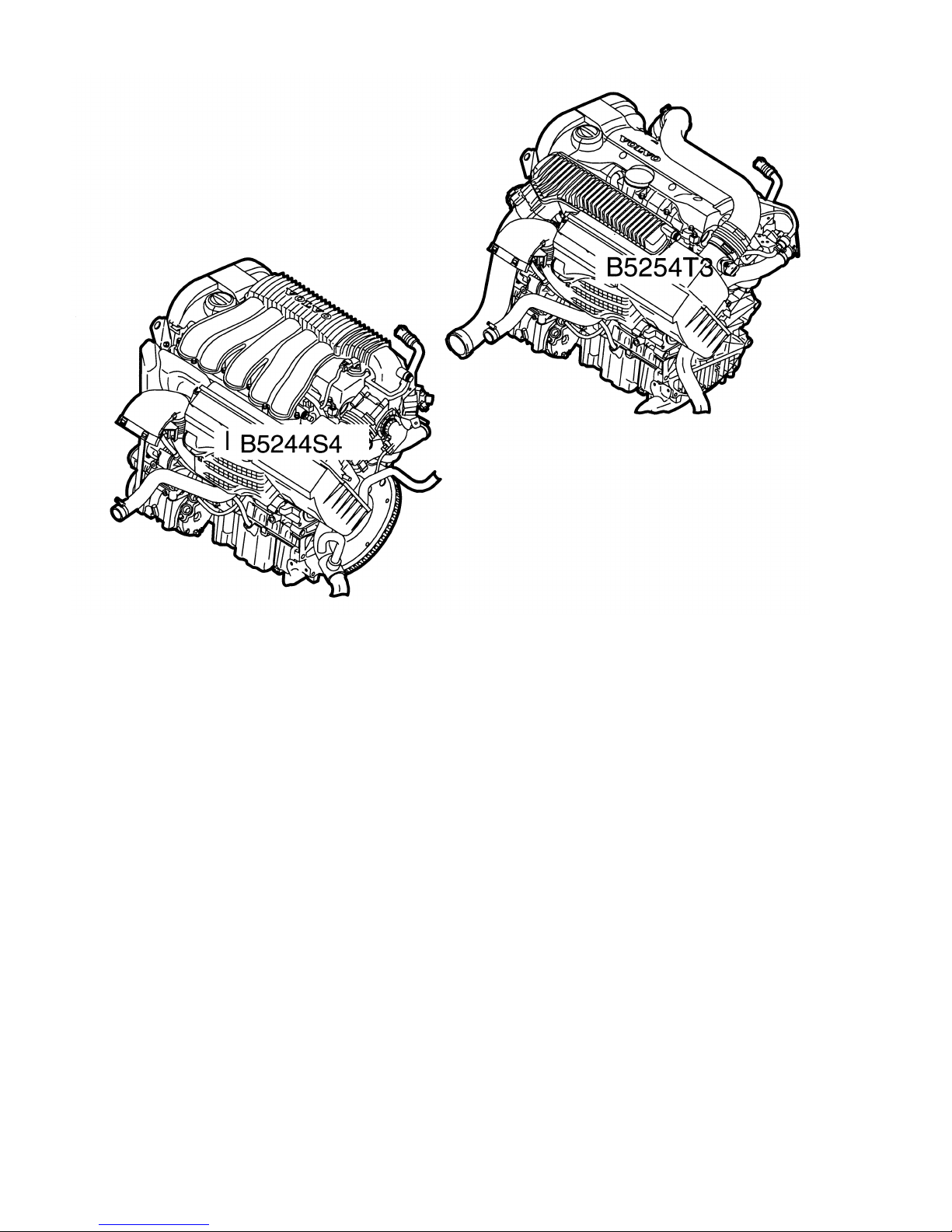
ENGINES
B5244S4 AND B5254T3
I
NTRODUCTION
The engines are designed to be compact to fit into the smaller engine compartment (25 mm shorter
than the earlier 5 cylinder).
The engines have pendulum suspension-type motor mounts.
The air cleaner housing and control module box are integrated.
The intake manifold is also used as a cover for the engine (the turbocharged engine has a separate
cover).
The engines have two drive belts (one for the alternator and one for the air conditioning compressor).
The naturally aspirated B5244S4 engine has a Denso engine management system.
The turbocharged B5254T3 engine has a
Bosch
engine management system.
Engines
B5244S4 and B5254T3
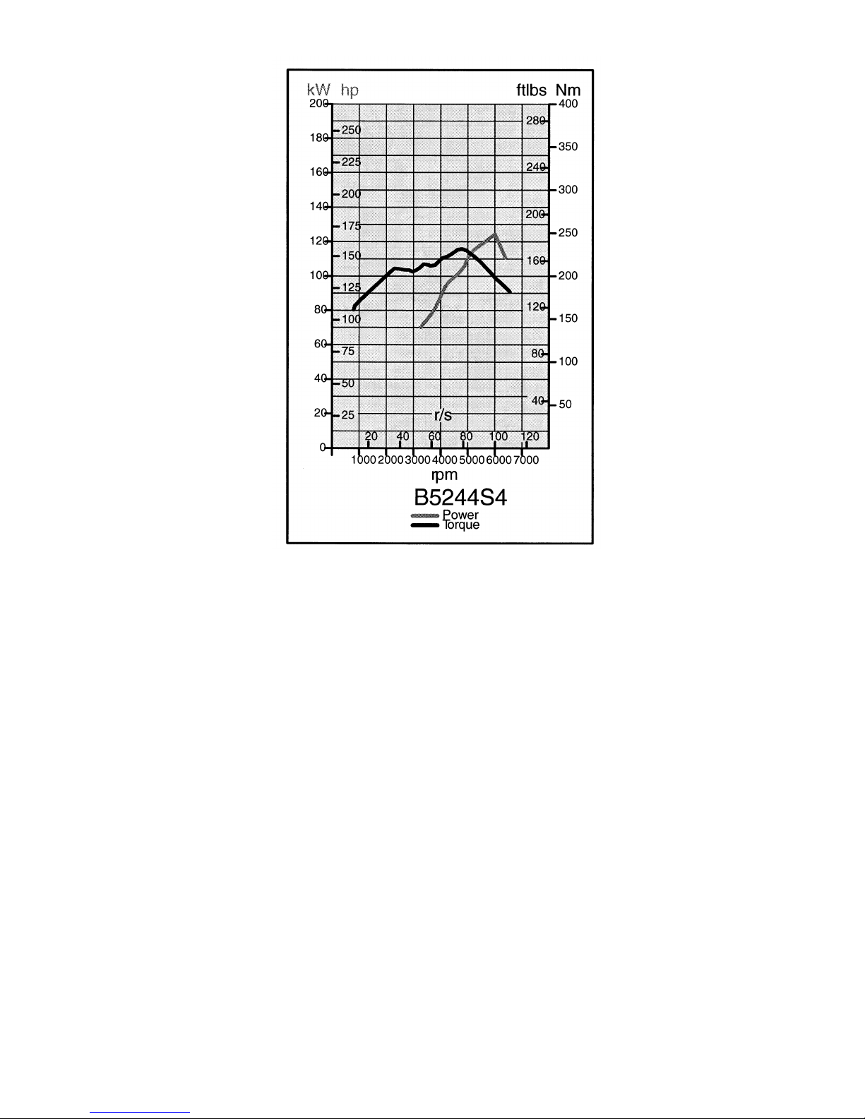
B5244S4
GENERAL
B5244S4
(170 hp) engine:
The B5244S4 is based on the B5244S (ULEV) engine.
I
ntroduced in the S40 and V50 only.
Uses Denso engine management system.
Meets U.S. ULEV emissions standards.
Uses automatic transmission AW55-51 (manual transmission M66 will be introduced later).
•
When cold, the engine warm-up uses the 'Wide Range' concept.
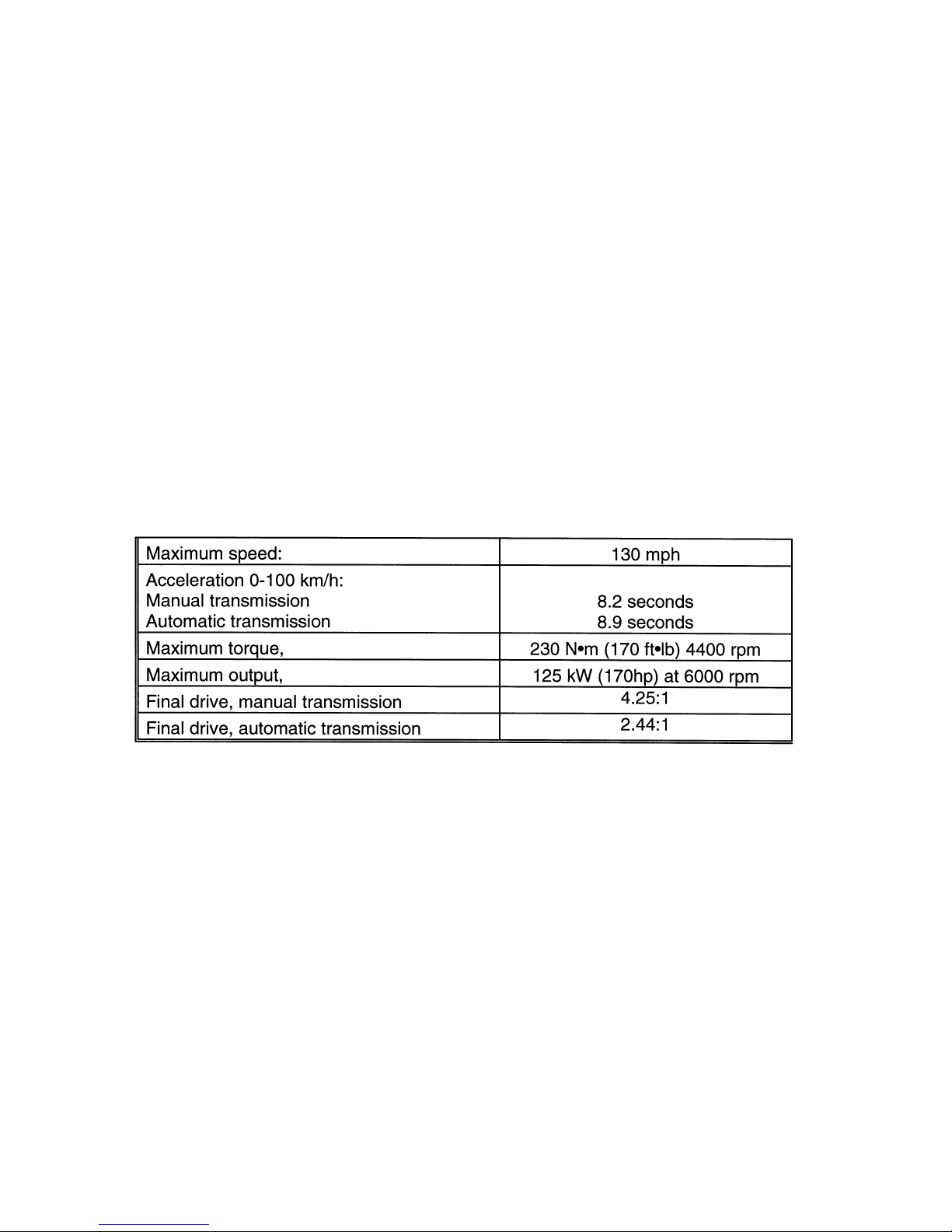
TECHNICAL DATA

OVERVIEW OF THE B5244S4
Crankshaft, Main
Bearings
Stroke 90.0 mm; forged; weight 21571 grams; connecting rod pins:
Main bearing journals:
Both the upper and lower main bearings are aluminum.
Connecting Rods, Connecting Rod Bearings
•
Center to center length 143 mm; weight 644 grams.
Both the upper and lower bearings are aluminum.
Pistons
Graphite-coated pistons.
Wrist pin diameter/length = 21 mm/57 mm.
Weight 397 grams with piston rings, snap rings and wrist pins.
Weight piston alone 282 grams.
-
Graphite-coated pistons have a play of approximately 0.04 mm between the piston and cylinder
before the graphite coating. The graphite coating is approximately 0.01 mm on either side of the
piston.
The graphite coating wears but never completely disappears; it penetrates the outer
l
ayer of the piston.
65.00 mm.
50.00 mm.

Cylinder Head, Camshafts
The engine mounting bracket is located on the cylinder head and secured with 5 bolts that must be
tightened in three stages. See VADIS.
Cooling is more effective due to larger coolant ducts and a more directed flow between the exhaust
ports and around the spark plug wells.
There are ducts for crankcase gases beside each cylinder's intake port.
•
Cylinder head with Continuous Variable Valve Timing (CVVT) only on the intake camshaft.
•
CVVT camshaft angle variation:
- Intake = 50 crankshaft degrees.
Camshaft Housing
•
The camshaft position sensors are integrated into the camshaft housing.
•
The CVVT solenoid has a new location.
•
The oil filler pipe has been moved to the side nearest the CVVT solenoid because of the new intake
manifold.
•
New version of CVVT (Advance and Retard).
Oil Filter /
Oil Trap
The filter and trap are integrated into one unit.
The filter has been moved from the oil pan to the intake side of the engine. This causes less oil spillage
when replacing the filter than on previous engines.
Oil flows from the outside in, through the filter.
To ensure that oil still flows even if the filter is clogged, there is an overflow valve in the cover that
opens at 11 kPa and when starting the vehicle from cold (-20°C to -25°C).
Oil Separation
The oil trap is manufactured in die-cast aluminum and consists of one chamber, 3 cyclonic separators,
1
spring loaded membrane and a plastic cover.
The chamber roughly separates oil and gases.
For further separation the gases are ducted to the cyclones which finely separate the oil from gases.
The cyclones are plastic and cannot be replaced.
The separated oil runs to the bottom of the cyclones and on to the oil pan.
The crankcase gases go up to a spring-loaded membrane that opens at a pressure of -5 kPa to
+3 kPa.
When the gases have passed the membrane they travel via a hose to the intake manifold and then to
the intake gasket which has calibrated holes for each cylinder. This improves the distribution of the
crankcase gases.
Spark Plugs
To reduce carbon deposits when starting the vehicle from cold, the ceramic is thinner at the tip of the
spark plug. This is called Quick Heat.
The spark plugs have a longer thread = 26.5 mm (previously 19.0 mm).
The spark plugs have three electrodes.
The tightening torque is 28 N
•m
(+l- 3 N•m).
2501463
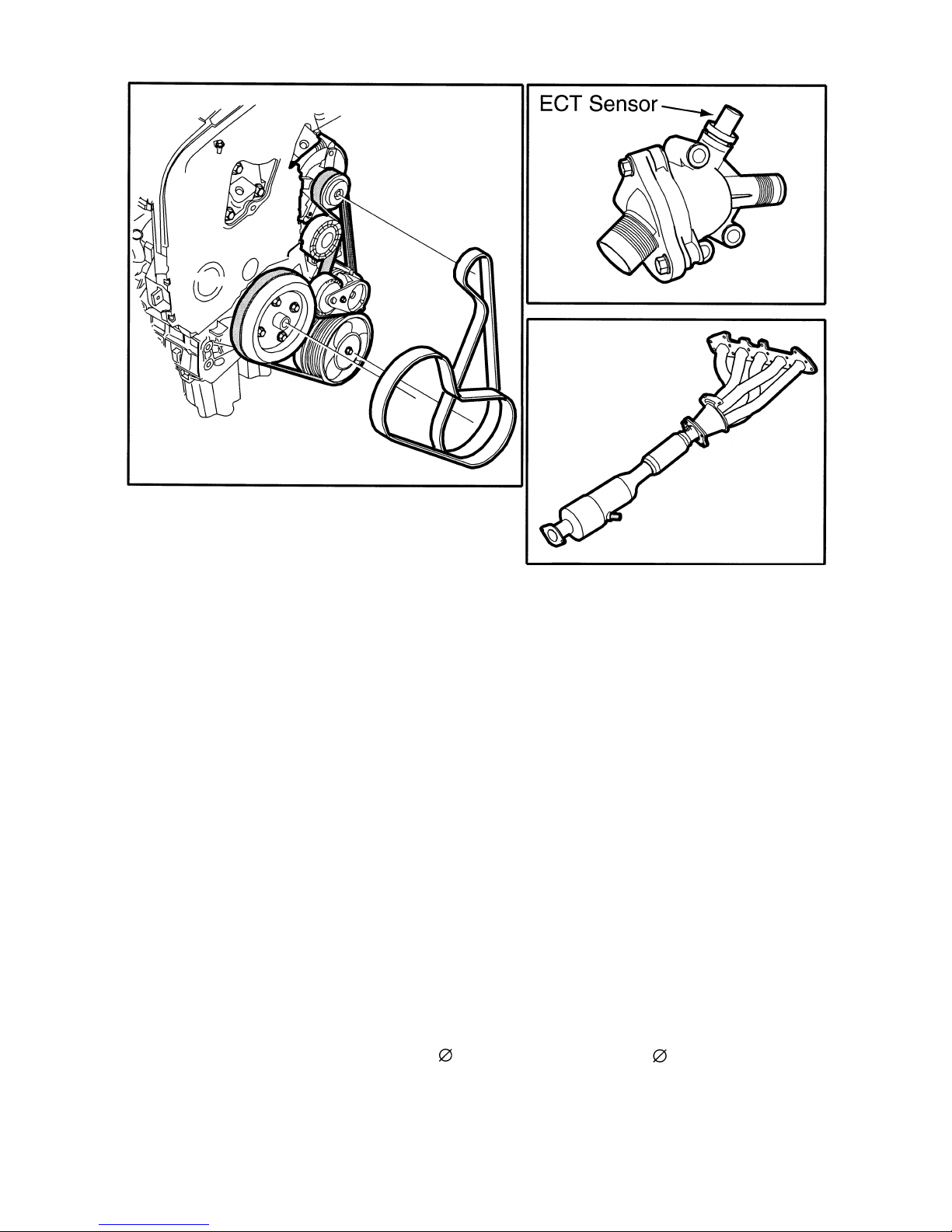
Thermostat Housing
The thermostat housing has been moved to the block on the intake side of the engine.
Auxiliary Equipment
•
The design of the auxiliary equipment has been changed to make the engine shorter.
•
The NC compressor and alternator have their own drive belts. The alternator now rotates
clockwise.
•
The drive belts are in reinforced rubber (Poly-V), and are tensioned by their own mechanical
tensioners.
•
The tensioner consists of a spring and a friction element.
Catalytic Converter
The catalytic converter under the floor, Under Floor Catalyst (UFC), has double oval ceramic monoliths.
The flow through the catalytic converter is optimized to reduce resistance.
Exhaust
Pipe
The exhaust system has been developed to reduce wind resistance under the car.
60 mm) on the side of the
60 mm) with and tail pipe
hidden).
The exhaust system consists of a single pipe
muffler (the tail pipe has been designed so it is
2501 469j
I
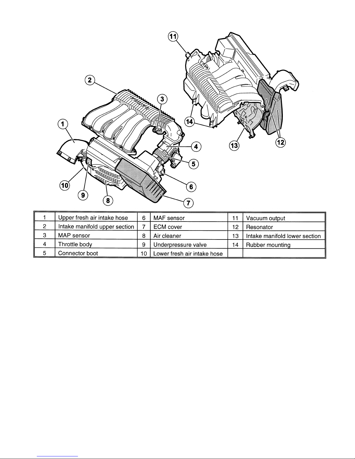
NTAKE SYSTEM
I
ntake Manifold Lower Section
•
The intake system is divided into upper and lower sections.
•
The intake system has a total volume of 5.3 liters with tuned lengths of pipe.
-
The injectors are located on the lower manifold so the fuel mixes with the turbulent air as
efficiently as possible.
•
The position of the injectors is optimized to minimize fuel film formation and improve emissions.
-
The lower intake manifold is aluminum to protect the fuel injection nozzles in the event of an
accident.
•
There are individual ducts to each intake port to distribute the crankcase gases evenly between the
cylinders.
•
To better control the exact volume of crankcase gases used in combustion, the gasket between the
l
ower intake manifold and the cylinder head has calibrated holes for the crankcase gases.

I
ntake Manifold Upper Section
•
The upper intake manifold is plastic.
•
Each cylinder has an intake pipe that comes off a plenum chamber.
•
The bend in the intake manifold after the throttle body acts as a mixing chamber and evenly
distributes air to the cylinders.
•
The MAP sensor is located in the intake manifold.
Air Cleaner
•
The air cleaner and air cleaner housing are designed to minimize drops in pressure and to be as
compact as possible.
•
The air cleaner housing has a volume of 9.1 liters.
•
The air cleaner housing and control module box are integrated into one unit.
The air cleaner is a cassette that is inserted vertically. The cover above the filter is mounted using two
bolts.
•
The air cleaner unit is mounted on 3 brackets.
•
A fine net is located behind the ECM to reduce the cyclone effect in the air flow.
•
A spring-loaded valve is located beside the air cleaner and opens when the pressure drops below 6
kPa if the air intake pipe is restricted.
Engine Cooling Fan
6 fixed speeds
7 blades
 Loading...