


Workshop Manual
Engine Unit
AQ125A, B
AQ145A, B
C
2(0)


Contents
Safety Precautions ............................................................................................................. 2
General Information ...........................................................................................................5
Repair Instructions ............................................................................................................6
Presentation ....................................................................................................................... 8
Repair Instructions
Disassembling, Overhauling and Inspection
Electrical parts, carburetor ...................................................................................................9
Heating exchanger, exhaust pipe, oil filter.................................................................. 10–11
Oil cooler, sea water pump ............................................................................................... 12
Circulation pump, belt pulley, marking the timing belt ...................................................... 13
Belt tensioner, intermediate pulley, camshaft pulley......................................................... 14
Sealing flange, flywheel cover .......................................................................................... 15
Vibration damper, intermediate shaft ................................................................................ 16
Camshaft........................................................................................................................... 16
Cylinder head valves ..................................................................................................16–18
Valve seats, guides, springs, pushers ........................................................................ 19–22
Flywheel, sealing .............................................................................................................. 22
Lubricating oil pump, pistons, crankshaft.................................................................... 23–24
Cylinders, pistons, connecting rods, crankshaft.......................................................... 25–28
Fuel pump, oil cooler, lubricating oil pump ................................................................. 28–30
Heat exchanger, carburetor, flywheel cover................................................................ 31–33
Assembling
Crankshaft, pistons, lubrication oil pump, flywheel ..................................................... 33–35
Oil sump, cylinder head, camshaft .............................................................................. 36–37
Intermediate shaft, seals, camshaft gear wheel .......................................................... 38–39
Intermediate gear, marking, timing belt ....................................................................... 40–42
Oil pump drive, circulation pump, valve adjustment.................................................... 42–46
Distributor, oil cooler, exhaust pipe, heat exchanger .................................................. 46–48
Lubrication oil filter, sea water pump, expansion tank ................................................ 48–49
Thermostat sea water strainer, alternator.................................................................... 49–50
Starter motor, induction pipe, carburetor ..................................................................... 50–51
Electric wiring diagram ................................................................................................... 52
Fault finding chart ........................................................................................................... 53
Special tools .............................................................................................................. 54–55
Technical data AQ125A, AQ145A............................................................................ 56–60
Valve adjusting kit........................................................................................................... 61
Technical data AQ125B, AQ145B............................................................................ 62–68
1

Safety Precautions
Introduction
This Workshop Manual contains technical data, descriptions and repair instructions for Volvo Penta
products or product versions contained in the contents list. Ensure that the correct workshop literature is being used.
Read the safety information and the Workshop
Manual “General Information” and “Repair Instructions” carefully before starting work.
Important
In this book and on the engine you will find the following special warning symbols.
WARNING! If these instructions are not followed there is a danger of personal injury, extensive damage to the product or serious mechanical malfunction.
IMPORTANT! Used to draw your attention to
something that can cause damage, product
malfunction or damage to property.
NOTE! Used to draw your attention to important infor
mation that will facilitate work or operations.
Check that the warning or information decals
on the product are always clearly visible. Replace decals that have been damaged or painted over.
Never use start spray or similar to start the
engine. The starter element may cause an explosion in the inlet manifold. Danger of personal injury.
Avoid opening the filler cap for engine coolant
system (freshwater cooled engines) when the
engine is still hot. Steam or hot coolant can
spray out. Open the coolant filler cap carefully
and slowly to release pressure before removing the cap completely. Take great care if a
cock, plug or engine coolant line must be removed from a hot engine. It is difficult to anticipate in which direction steam or hot coolant
can spray out.
Below is a summary of the risks and safety precautions you should always observe or carry out when
operating or servicing the engine.
Immobilize the engine by turning off the power
supply to the engine at the main switch
(switches) and lock it (them) in the OFF position before starting work. Set up a warning notice at the engine control point or helm.
Generally, all servicing should be carried out
with the engine switched off. Some work (carrying out certain adjustments for example) requires the engine to be running. Approaching
a running engine is dangerous. Loose clothing
or long hair can fasten in rotating parts and
cause serious personal injury.
If working in proximity to a running engine,
careless movements or a dropped tool can result in personal injury. Avoid burns. Take precautions to avoid hot surfaces (exhausts, turbochargers, charge air pipes and starter
elements etc.) and liquids in supply lines and
hoses when the engine is running or has been
turned off immediately prior to starting work
on it. Reinstall all protective parts removed
during service operations before starting the
engine.
Hot oil can cause burns. Avoid skin contact
with hot oil. Ensure that the lubrication system
is not under pressure before commencing
work on it. Never start or operate the engine
with the oil filler cap removed, otherwise oil
could be ejected.
Stop the engine and close the sea cock before
carrying out operations on the engine cooling
system.
Only start the engine in a well-ventilated area.
If operating the engine in an enclosed space,
ensure that exhaust gases and crankcase
ventilation emissions are ventilated out of the
working area.
Always use protective goggles where there is
a danger of pieces of metal, sparks from
grinding, acid or other chemicals being thrown
into your eyes. Your eyes are very sensitive,
injury can lead to loss of sight!
2

Avoid skin contact with oil. Long-term or repeated contact with oil can remove the natural
oils from your skin. The result can be irritation, dry skin, eczema and other skin problems. Used oil is more dangerous to health
than new oil. Use protective gloves and avoid
using oil-soaked clothes and rags. Wash regularly, especially before meals. Use the correct
barrier cream to prevent dry skin and to make
cleaning your skin easier.
Most chemicals used in products (engine and
transmission oils, glycol, petrol and diesel oil)
and workshop chemicals (solvents and paints)
are hazardous to health Read the instructions
on the product packaging carefully! Always
follow safety instructions (using breathing
apparatus, protective goggles and gloves for
example). Ensure that other personnel are not
unwittingly exposed to hazardous substances
(by breathing them in for example). Ensure
that ventilation is good. Handle used and excess chemicals according to instructions.
All fuels and many chemicals are inflammable.
Ensure that a naked flame or sparks cannot
ignite fuel or chemicals. Combined with air in
certain ratios, petrol, some solvents and hydrogen from batteries are easily inflammable
and explosive. Smoking is prohibited! Ensure
that ventilation is good and that the necessary
safety precautions have been taken before
carrying out welding or grinding work. Always
have a fire extinguisher to hand in the workplace.
Store oil and fuel-soaked rags and fuel and oil
filters safely. In certain conditions oil-soaked
rags can spontaneously ignite. Used fuel and
oil filters are environmentally dangerous waste
and must be deposited at an approved site for
destruction together with used lubricating oil,
contaminated fuel, paint remnants, solvent,
degreasing agents and waste from washing
parts.
Never allow a naked flame or electric sparks
near the batteries. Never smoke in proximity
to the batteries. The batteries give off hydrogen gas during charging which when mixed
with air can form an explosive gas – oxyhydrogen. This gas is easily ignited and highly
volatile. Incorrect connection of the battery
can cause a spark which is sufficient to cause
an explosion with resulting damage. Do not
disturb battery connections when starting the
engine (spark risk) and do not lean over batteries.
Never mix up the positive and negative battery terminals when installing. Incorrect installation can result in serious damage to electrical equipment. Refer to wiring diagrams.
Always use protective goggles when charging
and handling batteries. The battery electrolyte
contains extremely corrosive sulfuric acid. If
this comes into contact with the skin, wash
immediately with soap and plenty of water. If
battery acid comes into contact with the eyes,
immediately flush with copious amounts of
water and obtain medical assistance.
Turn off the engine and turn off power at main
switch(es) before carrying out work on the
electrical system.
Use the lifting eyes mounted on the engine/reverse gear when lifting the drive unit.
Always check that lifting equipment is in good
condition and has sufficient load capacity to
lift the engine (engine weight including reverse
gear and any extra equipment installed).
To ensure safe handling and to avoid damaging engine components on top of the engine,
use a lifting beam to raise the engine. All
chains and cables should run parallel to each
other and as perpendicular as possible in relation to the top of the engine.
If extra equipment is installed on the engine
altering its center of gravity, a special lifting
device is required to achieve the correct balance for safe handling.
Never carry out work on an engine suspended
on a hoist.
3

Never remove heavy components alone, even
where secure lifting equipment such as secured blocks are being used. Even where lifting equipment is being used it is best to carry
out the work with two people; one to operate
the lifting equipment and the other to ensure
that components are not trapped and damaged
when being lifted. When working on-board ensure that there is sufficient space to remove
components without danger of injury or damage.
Components in the electrical system, ignition
system (gasoline engines) and fuel system on
Volvo Penta products are designed and constructed to minimize the risk of fire and explosion. The engine must not be run in areas
where there are explosive materials.
Always use fuels recommended by Volvo Penta. Refer to the Instruction Book. The use of
lower quality fuels can damage the engine. On
a diesel engine poor quality fuel can cause the
control rod to seize and the engine to overrev
with the resulting risk of damage to the engine
and personal injury. Poor fuel quality can also
lead to higher maintenance costs.
4

General information
About the workshop manual
This workshop manual contains technical specification, descriptions and instructions for repairing
the standard versions of the following engines
AQ125A, B – AQ145A, B. The workshop manual
displays the operations carried out on any of the
engines above. As a result the illustrations and pictures in the manual that show certain parts on the
engines, do not in some cases apply to all the engines listed above. However the repair and service
operations described are the same in all essential
details. Where they are not the same this is stated
in the manual and where the difference is considerable the operations are described separately. Engine designations and numbers are given on the
number plate. The engine designation and number
should be given in all correspondence about the engine.
This Workshop Manual has been developed primarily for Volvo Penta service workshops and qualified
personnel. Persons using this book are assumed to
have a grounding in marine drive systems and be
able to carry out related mechanical and electrical
work.
Volvo Penta is continuously developing their products. We therefore reserve the right to make changes. All the information contained in this book is
based on product data available at the time of going
to print. Any essential changes or modifications introduced into production or updated or revised service methods introduced after the date of publication will be provided in the form of Service Bulletins.
Replacement parts
Replacement parts for electrical and fuel systems
are subject to statutory requirements (US Coast
Guard Safety Regulations for example). Volvo Penta Genuine parts meet these requirements. Any
type of damage which results from the use of nonoriginal Volvo Penta replacement parts for the product will not be covered under any warranty provided
by Volvo Penta.
5

Repair instructions
The working methods described in the Service Manual apply to work carried out in a workshop. The engine has been removed from the boat and is installed in an engine fixture. Unless otherwise stated
reconditioning work which can be carried out with
the engine in place follows the same working
method.
Warning symbols occurring in the Workshop Manual (for their meaning see
WARNING!
IMPORTANT!
NOTE!
are not in any way comprehensive since it is
impossible to predict every circumstance under
which service work or repairs may be carried out.
For this reason we can only highlight the risks that
can arise when work is carried out incorrectly in a
well-equipped workshop using working methods and
tools developed by us.
All procedures for which there are Volvo Penta special tools in this Workshop Manual are carried out
using these. Special tools are developed to rationalize working methods and make procedures as safe
as possible. It is therefore the responsibility of any
person using tools or working methods other than
the ones recommended by us to ensure that there is
no danger of injury, damage or malfunction resulting
from these.
In some cases there may be special safety precautions and instructions for the use of tools and chemicals contained in this Workshop Manual. These
special instructions should always be followed if
there are no separate instructions in the Workshop
Manual.
Certain elementary precautions and common sense
can prevent most risks arising. A clean workplace
and engine eliminates much of the danger of injury
and malfunction.
It is of the greatest importance that no dirt or foreign particles get into the fuel system, lubrication
system, intake system, turbocharger, bearings and
seals when they are being worked on. The result
can be malfunction or a shorter operational life.
Safety information
)
Our joint responsibility
Each engine consists of many connected systems
and components. If a component deviates from its
technical specification the environmental impact of
an otherwise good engine may be increased significantly. It is therefore vital that wear tolerances are
maintained, that systems that can be adjusted are
adjusted properly and that Volvo Penta Genuine
Parts as used. The engine Maintenance Schedule
must be followed.
Some systems, such as the components in the fuel
system, require special expertise and special testing equipment for service and maintenance. Some
components are sealed at the factory for environmental reasons. No work should be carried out on
sealed components except by authorized personnel.
Bear in mind that most chemicals used on boats are
harmful to the environment if used incorrectly. Volvo Penta recommends the use of biodegradable degreasing agents for cleaning engine components,
unless otherwise stated in a workshop manual.
Take special care when working on-board, that oil
and waste is taken for destruction and is not accidentally pumped into the environment with bilge water.
Tightening torques
Tightening torques for vital joints that must be
tightened with a torque wrench are listed in workshop manual “Technical Data”: “Tightening Torques”
and are contained in work descriptions in this Manual. All torques apply for cleaned threads, screw
heads and mating surfaces. Torques apply for lightly oiled or dry threads. If lubricants, locking fluid or
sealing compound are required for a screwed joint
this information will be contained in the work description and in “Tightening Torques” Where no
tightening torque is stated for a joint use the general
tightening torques according to the tables below.
The tightening torques stated are a guide and the
joint does not have to be tightened using a torque
wrench.
Dimension Tightening Torques
Nm lbt.ft
M5 6 4.4
M6 10 7.4
M8 25 18.4
M10 50 36.9
M12 80 59.0
M14 140 103.3
6

Tightening torques-protractor (angle)
tightening
Tightening using both a torque setting and a protractor angle requires
that first the recommended torque is
applied using a torque wrench and
then the recommended angle is added according to the protractor scale.
Example: a 90° protractor tightening
means that the joint is tightened a
further 1/4 turn in one operation after the stated tightening torque has
been applied.
Locknuts
Do not re-use lock nuts that have been removed
during dismantling as they have reduced service life
when re-used - use new nuts when assembling or
reinstalling. For lock nuts with a plastic insert such
as Nylock® the tightening torque stated in the table
is reduced if the Nylock® nut has the same head
height as a standard hexagonal nut without plastic
insert. Reduce the tightening torque by 25% for bolt
size 8 mm or larger. Where Nylock® nuts are higher, or of the same height as a standard hexagonal
nut, the tightening torques given in the table apply.
Tolerance classes
In this Volvo Penta Service Manual the user will find
that each section where these agents are applied in
production states which type was used on the engine.
During service operations use the same agent or an
alternative from a different manufacturer.
Make sure that mating surfaces are dry and free
from oil, grease, paint and anti-corrosion agent before applying sealant or locking fluid. Always follow
the manufacturer’s instructions for use regarding;
temperature range, curing time and any other instructions for the product.
Two different basic types of agent are used on the
engine and these are:
RTV agent (Room temperature vulcanizing). Use for
gaskets, sealing gasket joints or coating gaskets.
RTV agent is clearly visible when a component has
been dismantled; old RTV must be removed before
the joint is resealed. Old sealant can be removed
using methylated spirits in all cases.
Anaerobic agents. These agents cure in an absence
of air. They are used when two solid parts, for example cast components, are installed face-to-face
without a gasket. They are also commonly used to
secure plugs, threads in stud bolts, cocks, oil pressure switches and so on. The cured material is
glass-like and it is therefore colored to make it visible. Cured anaerobic agents are extremely resistant to solvents and the old agent cannot be removed. When reinstalling the part is carefully
degreased and then new sealant is applied.
Screws and nuts are divided into different strength
classes, the class is indicated by the number on the
bolt head. A high number indicates stronger material, for example a bolt marked 10-9 indicates a higher tolerance than one marked 8-8. It is therefore important that bolts removed during the disassembly
of a bolted joint must be reinstalled in their original
position when assembling the joint. If a bolt must be
replaced check in the replacement parts catalogue
to make sure the correct bolt is used.
Sealants
A number of sealants and locking liquids are used
on the engines. The agents have varying properties
and are used for different types of jointing trengths,
operating temperature ranges, resistance to oil and
other chemicals and for the different materials and
gap sizes in the engines.
To ensure service work is correctly carried out it is
important that the correct sealant and locking fluid
type is used on the joint where the agents are required.
7
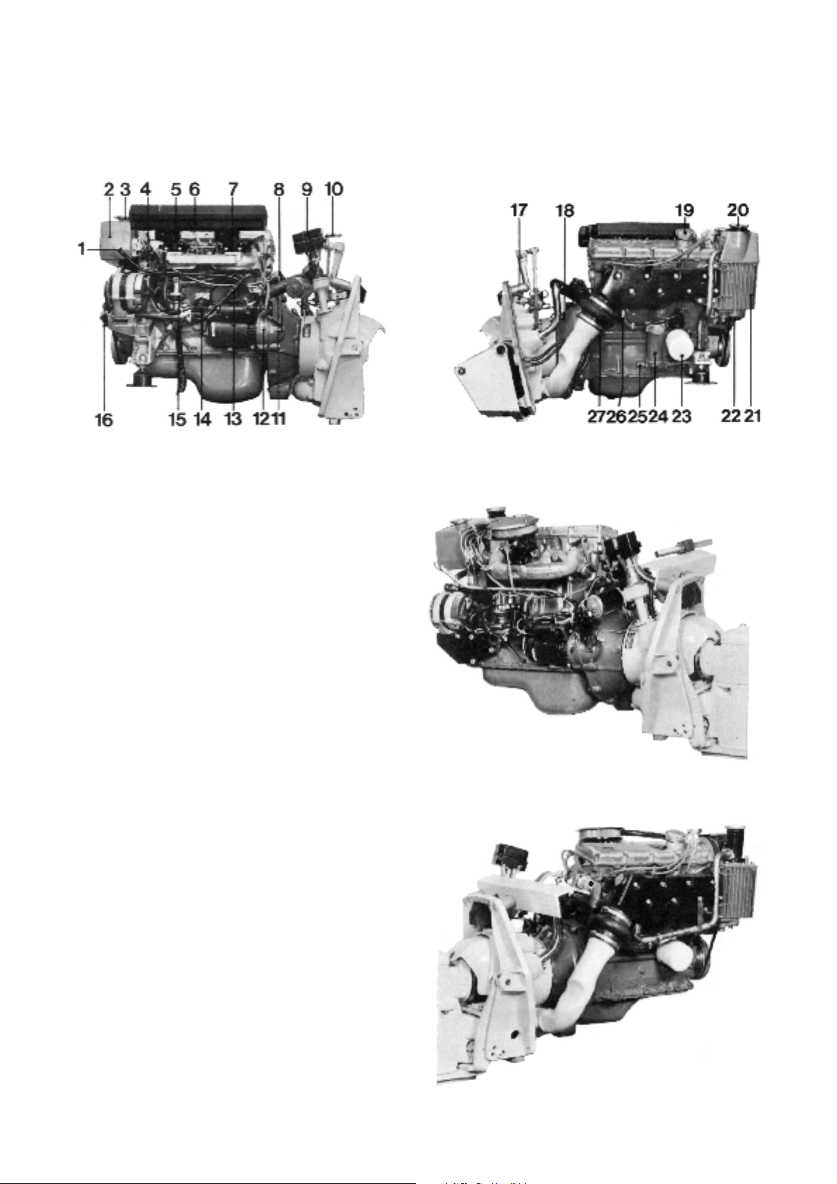
Presentation
AQ145A
1. Oil dipstick
2. Fresh water tank
3. Filler cap, checking, fresh water
4. Distributor
5. Carburettor, front (AQ125 has only one)
6. Intake air silencer
7. Carburettor, rear
8. Ignition coil
9. Electro-mechanical lift device
10. Steering arm
11. Fuse box (exec. USA)
12. Serial number
13. Fuse (exec. USA)
14. Fuse (not USA)
15. Fuel pump
16. Sea water pump
17. Grease joint, upper steering shaft journal
18. Grease joint, drive shaft journal
19. Oil filler cap engine
20. Water filter
21. Heat exchanger
22. Draining, sea water
23. Luboil filter
24. Oil cooler (only AQ145A)
25. Draining, sea water
26. Draining, sea water
27. Draining, fresh water
AQ145A
AQ125
AQ125
8

Repair Instructions
1. AQ145. Remove the four screws and pull the in-
duction silencer to one side so that it comes free
from the evacuation tube (1). AQ125. Remove the
cover.
3. Remove the alternator, drive belt, cable harness,
ignition coil, main fuse, starter motor, ignition
cables and distributor. NOTE! Mark the cables
before they are removed.
2. Remove the air filters (1), the fuel pipe (2) between the feed pump and the carburetors and
unscrew the carburetors from the induction pipe.
AQ125 has only one carburetor.
4. Remove the cooling water pipe (1), and the
bracket for the ignition coil (2). Remove the screw
(3) and draw up the dip stick with its tube (4).
Then remove the feed pump (5) and the induction
pipe (6). NOTE! There are double gaskets plus an
intermediate washer on the feeder pump. There is
a lifting eye in the induction pipes rear screws.
There are no washers under the lifting eye.
9

5. Remove the thermostat housing and lift out the
thermostat.
NOTE! The forward lifting eye is screwed onto the
thermostat housing.
7. Remove the cap and lift out the strainer (1) from
the heat exchanger. Then pull up the rubber ring’s
tongue (2). The tongue is marked “UP”. The cover
(3) is now loose and can be lifted up. (Not on
AQ125.)
6. Remove and discard the O-ring (1) in the heat exchanger and if necessary, unscrew the holder (2)
for the ignition cables. The holder is fixed with two
guide pins.
8. Pull the heat exchanger’s fresh water section to
one side. The fresh water section is mounted on a
rubber bushing (1) and the water pipe (2), which
seals against an O-ring.
10

9. AQ145. Remove the cooling water pipes between
the seawater pump and the heat exchanger and
between the heat exchanger and the oil cooler.
(Between the heat exchanger and the exhaust
pipe on AQ125.)
11. Remove the cooling water pipe between the oil
cooler and the exhaust pipe. Not on AQ125. Then
remove the exhaust pipe.
10. Remove the remaining three screws (X) on the
heat exchanger and draw it to one side from the
circulation pump.
12. Unscrew the oil filter. Use tool 999 2903 or push a
screwdriver through the filter and work it loose.
NOTE! Be careful not to spill oil.
11

13. Remove the nut (1) and remove the oil cooler.
Only AQ145. Spanner width = 28 mm. Remove
the oil pressure
15. Remove the saltwater pump and the generator’s
tensioning bracket. The spanner width for the
saltwater pump is 10 mm. The other screws
which hold the cover have a spanner width of 8
mm. Check the impeller, the key and the packing
on the pump’s front side plus the sealing ring on
the pump’s rear side. Clean the pump and replace damaged parts.
14. AQ145. If the oil cooler’s channels are to be
cleaned when the exhaust pipe is fitted on the
engine the cooling water pipes (1) and (2) must
be removed. Undo the oil cooler’s screw (3) and
remove the lower cover.
The oil filter is then removed and the centre nut
(4) is loosened so that the oil cooler can be turned
to a horizontal position.
After this the insert’s channels can be cleaned.
16. Undo the cover’s two hexagonal socket screws
(6 mm key) and hexagonal screw (spanner width
10 mm). NOTE! The cover’s upper fixture is fitted
with a guide which means that the cover must be
withdrawn a few millimetres before it is free.
12
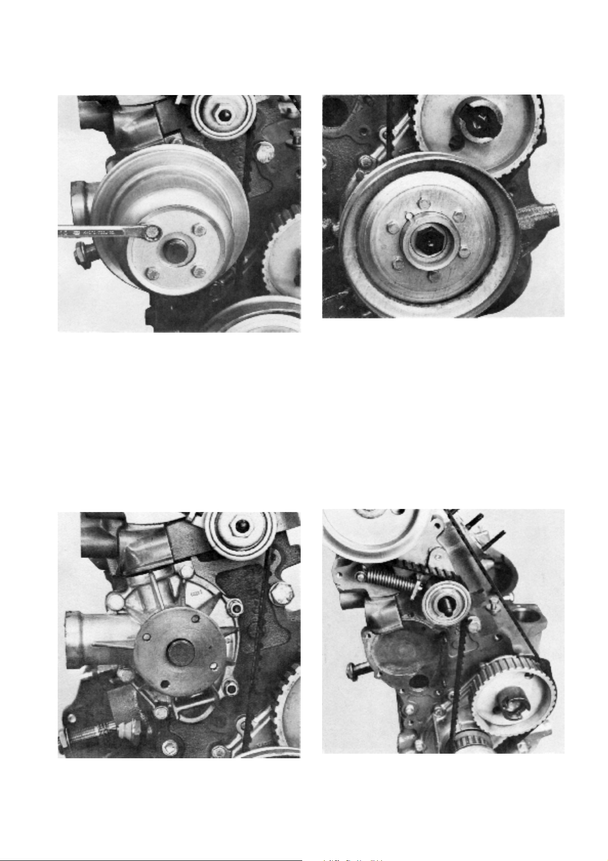
17. Remove the circulation pump’s pulley. The spanner width is 10 mm.
19. Remove the crankshaft pulley. Six screws. The
spanner width is 10 mm.
18. Remove the circulation pump. The spanner width
is 10 mm. There are four screws and two nuts
with washers. Discard the plain packing and the
rubber seal. NOTE! The pump is to be changed
as a complete unit if it has been damaged.
20. If the belt’s markings have disappeared the belt is
to be marked before it is removed. The marking of
the belt is carried out as follows: Make a mark by
the camshaft’s pulley marking. Make a mark by
the intermediate gear’s marking and two marks
on the crankshaft pulley’s marking. Undo and remove the nut and washer for the belt tensioner.
13
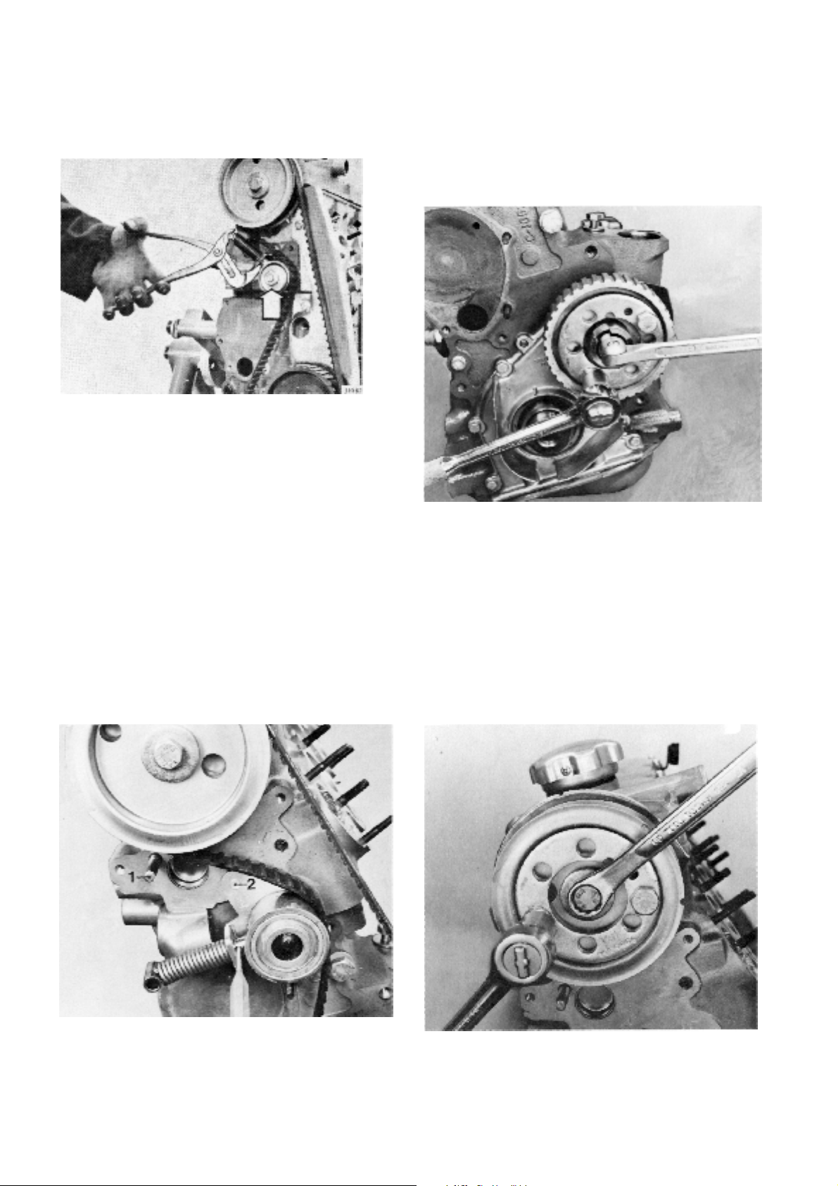
21. Slacken the belt by depressing the roller against
the spring pressure. Lock the spring by inserting a
3 mm (0.118") pin (e.g. a drill) in the hole on the
pressure pin.
23. Remove the cross piece from the intermediate
gear wheel. Check that cross piece is not damaged. Then remove the screw from the carrier.
Use counterforce 999 5034. Remove the carrier
and the pulley. Then remove the carrier from the
pulley. Mild force from the rear with a wooden
shaft or similar tool may be necessary.
22. Remove the belt tensioner from the shaft (1). The
belt tensioner’s guide pin 2 is now free after
which the belt tensioner is twisted and removed.
Then remove the belt. The shaft (1) can be replaced by unscrewing it from the cylinder head.
The timing belt is to be changed if the cord
re-inforcement and the rubber are beginning to
separate or if the tread on the timing belt is worn.
The timing belt is to be changed every five hundred hours.
24. Remove the pulley from the camshaft. Use counterforce 999 5034. Remove the pulley by hand.
Check that the outer and the inner guide plate’s
edges are not damaged so that these in turn can
damage the belt.
14

25. Remove the centre screw and pull off the carrier
and outer guide plate from the crankshaft.
27. Remove the screws from the sealing flange. The
flange is also tightened with two of the screws in
the oil sump. Remove the flange plate and remove the seals. Use tool 999 5025 for the small
seal and tool 999 5024 for the large seal.
26. Remove the key and pull off the pulley and the
inner guideplate from the crankshaft.
28. Unscrew the flywheel cover’s four screws and the
three screws which hold the protective plate on
the underside between the cover and the cylinder
block.
15
29. Remove the vibration damper’s six screws. Spanner width 13 mm. Carefully remove the vibration
damper from the three guide pins.
31. Pull out the intermediate shaft. Use the impact
tool 999 4030 where necessary. NOTE! Be careful to make sure that the intermediate shaft’s
gearwheel does not damage the bushes in the
cylinder block’s bearings.
30. Remove the cover and the bracket for the oil
pump drive. Then lift up the oil pump drive.
Cylinder head
32. Remove the valve cover, the gasket and the cres-
cent shaped rubber seal and check the marking
on the camshaft bearing caps.
16
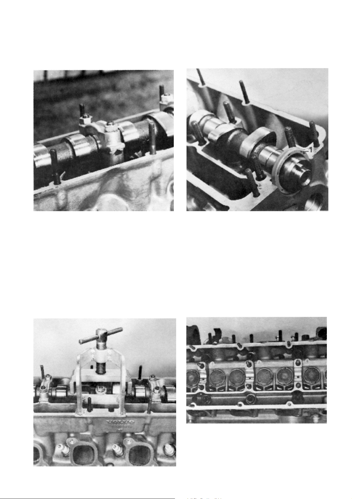
33. Remove the centre camshaft bearing cap. Spanner width 1/2". There are spring washers under
the nuts. When necessary use a chisel or similar
tool against the lug as shown by the arrow.
35. Remove the seal (1) from the camshaft. Then
undo the tool spindle and release the camshaft.
Remove the tool and lift out the camshaft.
34. Fit tool 999 5021 on the camshaft. Use the bearing cap’s nuts. The camshaft is held in position
with the tool. Undo the other four camshaft bearing caps.
36. Remove the screws in the cylinder head. Use
hexagonal socket key 10 mm. Lift away the cylinder head and remove the gasket. Remove the
spark plugs.
17
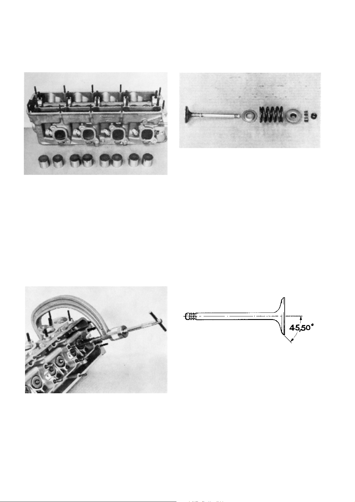
37. Lift up the valve pushers and place them in the
same order as they fit in the cylinder head.
39. Remove the rubber ring, collets, upper washers,
springs, lower washers and valves. Then remove
the valve seals from the inlet valve guides. Clean
all the parts. Remove carbon deposits from the
combustion chamber and the valves.
38. Remove the valves. Use valve spring compressor
884 580.
40. Grind the valves if necessary in a valve grinding
machine. The angle is the same for both the exhaust and the inlet valves.
18
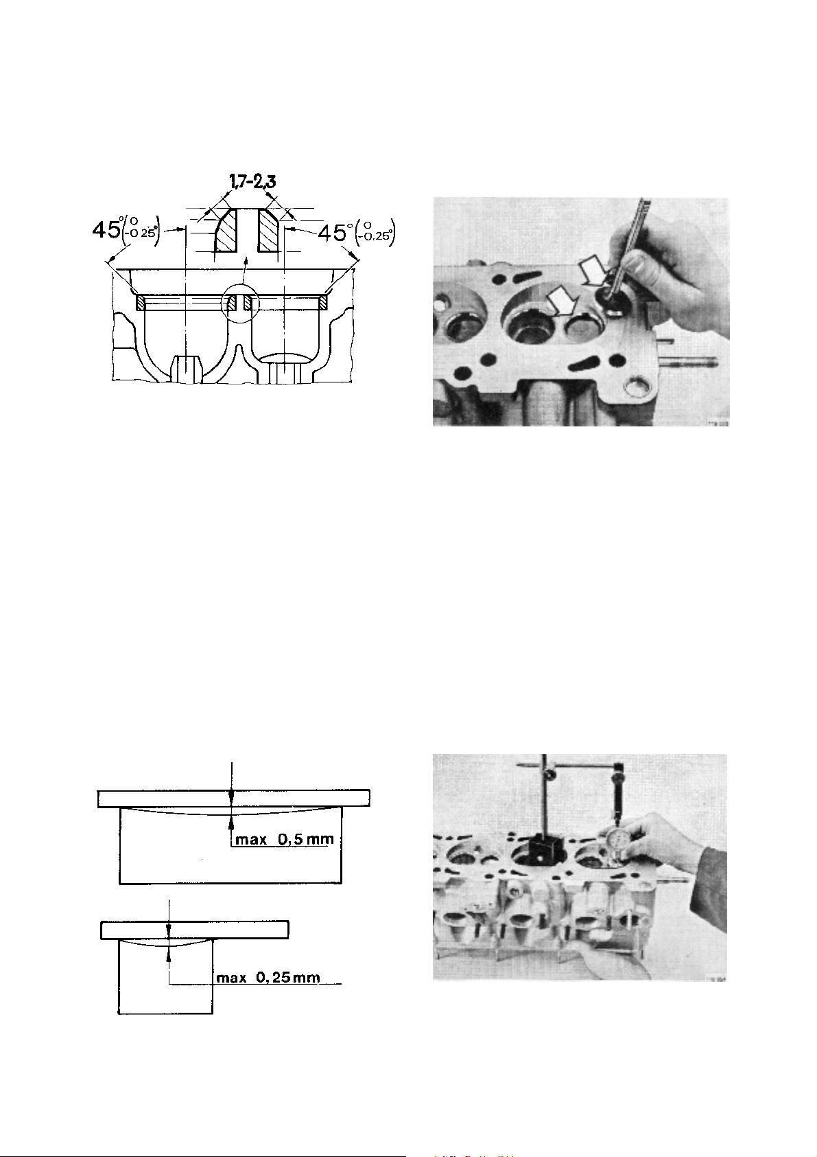
41. Mill or ream the valve seats. The angle is the
same for the exhaust and inlet valve seats.
43. Check that all the valves and the valve seats are
perfectly ground by marking the valve seat face
and turning it against the valve seat with light
pressure. If the marking is not evenly distributed
on the whole of the seat (leaking valve) the valve
is ground further and a new check is carried out
until the result is satisfactory.
42. Check the flatness of the cylinderhead. Use a
steel straight edge.
44. Check the wear of the valve and the valve guides.
The play for the inlet valve is 0.030–0.060 mm
(0.0012–0.0024") and for the exhaust 0.060–
0.090 mm (0.0024–0.0035").
19
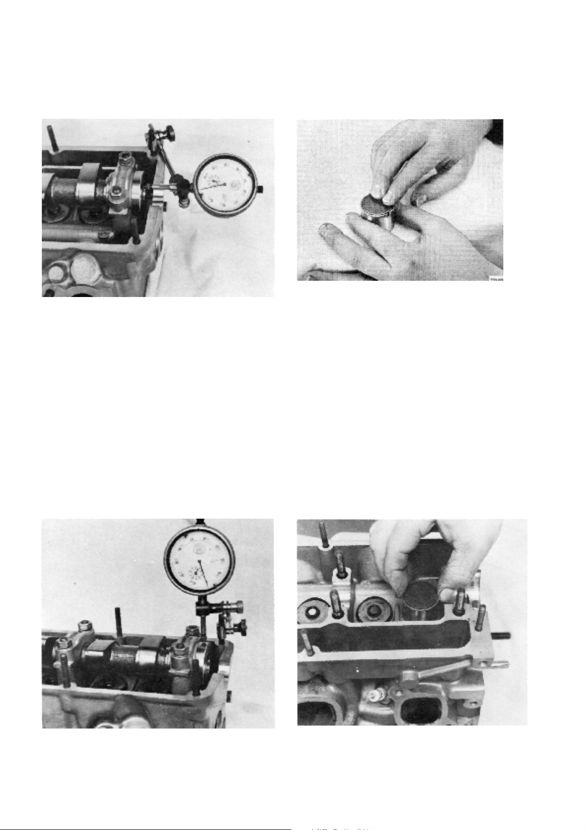
45. Replace the camshaft in the cylinder head and
check the axial play which is 0.1–0.4 mm
(0.004–0.016").
47. Check that the shims do not have too much play
in the valve pushers. If there are signs of wear on
the plain surface of the shim it should be changed. The play between the shim and the valve
presser is 0.009–0.068 mm (0.0004–0.0027).
46. Check the radial play which is 0.030–0.071 mm
(0.0012–0.0028").
48. Replace the valve pressers in the cylinder head
and check that the play is not too much or that
they do not stick. The play between the valve
pressers and the cylinder head is 0.030–0.075
mm (0.0012–0.0030").
20
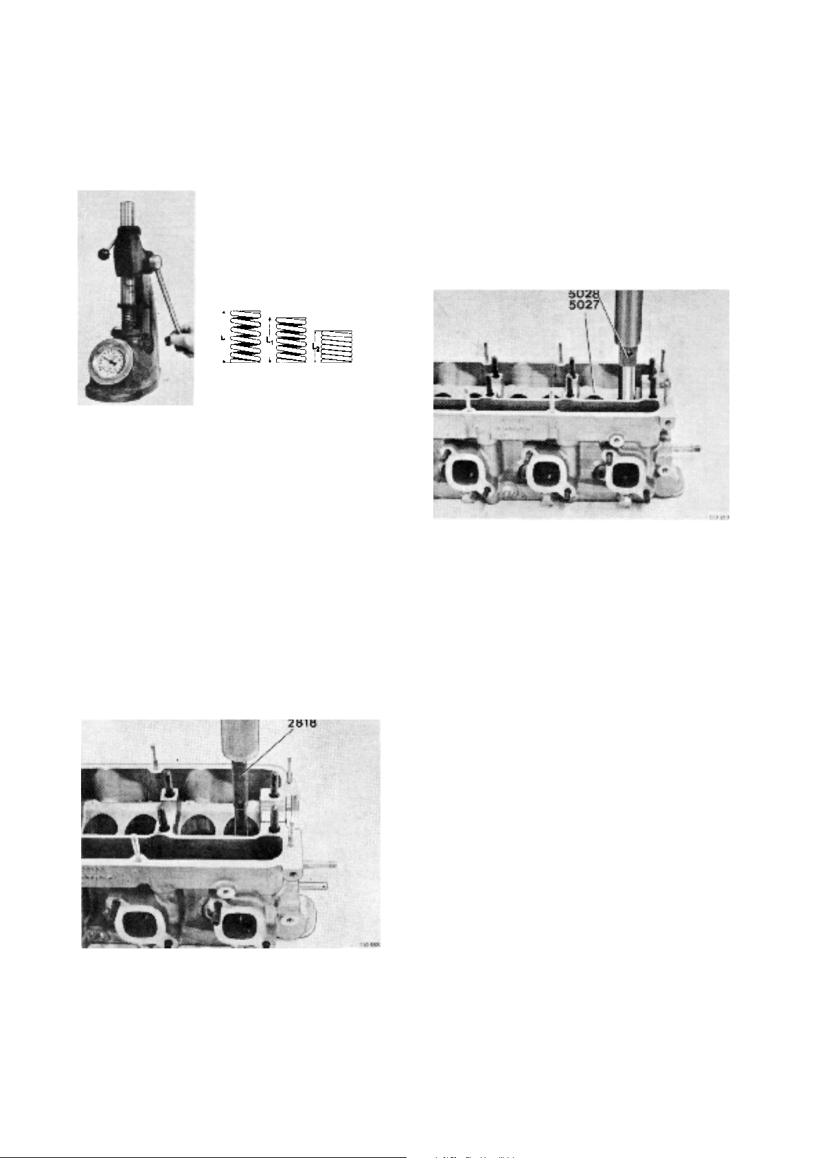
49. Check the valve springs.
Length unloaded 45 mm (1.77")
Length loaded with 300±20 N (67.2±4.48 lbf.)
38 mm (1.50")
Length loaded with 760±40 N (170±8.96 lbf.)
27 mm (1.06")
51. Fit the new valve guides. Use tool 999 5027 for
the inlet valves and tool 999 5028 for the exhaust
valves. The cylinder head is to be at room temperature. The pressing force for fitting the valve guides is to be at least 9000 N (900 kp) (2016 lbf). If
this pressing force is not obtained for the guides
the hole is to be reamed and a suitable oversized
valve guide is to be fitted. Press the guide down
until the tool comes up against the cylinder head.
This gives the guide a height above the valves
spring face around the guide of: 15.5±0.1 mm
(0.610±0.004") for the inlet valve and 18.0±0.1
mm (0.708±0.004") for the exhaust valve.
Changing the valve guides
50. Press up the valve guides with tool 999 2818.
Heat the cylinder head in 60°C (140°F) water.
21

52. Refit the valves.
1. Rubber ring
2. Upper valve washer
3. Collets
4. Valve springs
5. Valve stem seal (inlet)
6. Lower valve spring washer
Then refit the spark plugs.
NOTE! Make sure that the spark plug thread
screws in correctly so that the thread in the
aluminium cylinder head is not damaged. The
tightening torque is: 25–30 Nm (2.5–3.0 kpm)
(18.4–22.1 lbf. ft.)
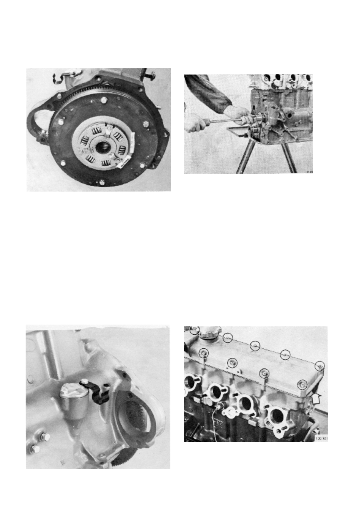
54. Remove the bearing for the input shaft. Use tool
999 4090. Remove the flywheel.
55. Remove the sealing flange. NOTE! Two screws
from the sump must also be removed.
53. Remove the locking ring for the bearing on the input shaft.
22
56. Remove the seal from the sealing flange with tool
999 2817.

57. Undo the screws and remove the oil sump. Then
remove the two screws in the lubricating oil pump
and lift out the pump with the pipe.
59. Note that the crankshaft and the crankshaft bearing caps are numbered. Then remove the bearing
caps and remove the bearing shells.
58. Remove the rubber ring for the oil pipe from the
cylinder block (And from the pipe where necessary).
60. Press out of the pistons from the cylinders. Let
the pistons fall on a soft surface so that they cannot be damaged. Then remove the piston rings.
Use piston ring pliers.
23

61. Remove the locking rings for the gudgeon pins
and press the gudgeon pins out.
63. Lift out the crankshaft and remove the bearing
shells from the block and the bearing caps.
62. Note that there are markings for the main bearing
caps. The bearing caps are marked 1–5 from the
transmission side. Remove the main bearing
caps.
CLEANING AND INSPECTION
64. Clean and carefully inspect the cylinder block.
The plugs for channels are to be removed before
cleaning. Re-fit the plugs after cleaning has been
completed. Tightening torque:
1/4 NPTF – 20 Nm (2 kpm) (14.7 lbf. ft.)
3/8 NPTF – 30 Nm (3 kpm) (22.1 lbf ft.)
24

65. Measure the cylinder liners with a special dial indicator. The measurement for greatest wear is
carried out immediately below top dead centre
and transverse to the engine. The measurement
for minimum wear is carried out at bottom dead
centre.
Standard cylinder diameter. AQ145
(C-marked): 96.00–96.01 mm (3.7795–3.7799 in.)
(D-marked). 96.01–96.02 mm (3.7799–3.7503 in.)
(E-marked): 96.02–96.03 mm (3.7803–3.7807 in.)
Oversize I
Standard cylinder diameter. AQ125
(D-marked): 92.01–92.02 mm (3.6224–3.6228 in.)
(G-marked): 92.03–92.04 mm (3.6232–3.6236 in.)
Oversize I: 92.500 mm (3.6417 in.)
: 96.300 mm (3.7973 in.)
II: 96.600 mm (3.8031 in.)
II: 93.000 mm (3.6614 in.)
Pistons
67. Measure the pistons with a micrometer at right
angles to the gudgeon pin hole and 6 mm (0.25")
from the lower edge.
Piston diameter standard. AQ145
(C-marked): 95.940–95.950 mm (3.7776–3.7780 in.)
(D-marked): 95.950–95.960 mm (3.7787–3.7791 in.)
(E-marked): 95.960–95.970 mm (3.7780–3.7783 in.)
(G-marked): 95.980–95.990 mm (3.7787–3.7791 in.)
Oversize I: (0.3–96.245): 96.237–96.252
(0.0118–3.7892): 3.7889–3.7894"
II: (0.6–96.545): 96.537–96.552
(0.0236–3.8010): 3.8007–3.8013"
Piston diameter standard. AQ125
(D-marked). 91.990–92.000 mm (3.6216–3.6220 m.)
(G-marked). 92.020–92.030 mm (3.6228–3.6232 in.)
Oversize I: (0.5–92.480): 92.474–92.492
(0.0196–3.6409): 3.6407–3.6414 in.)
II: (1.0–92.980): 92.977–92.992
(0.394–3.6606): 3.6605–3.6611 in.)
Classification marking
66. Each cylinder liner has a letter which indicates its
and pistons class.
Oversizes indicated by nominal diameter meas-
urement.
25

68. Piston play in cylinder: 0.05–0.07 mm (0.0020–
0.0028").
a. Piston diameter (A) is measured as stated
above.
b. The cylinder diameter is measuredat several
places crosswise to the engine and 30 mm
(1.2") (B) from block face and downwards to
bottom dead centre (C).
c. Calculate the piston’s maximum and minimum
clearances. (Deduct piston diameter to get cylinder liner’s maximum and minimum diameters).
70. Measure the piston ring gap with a feeler gauge.
Increase the gap with a special file where necessary.
The gap for AQ145 is to be:
Compression rings: 0.40–0.65 mm (0.0157–0.0256 in.)
Oil scraper ring: 0.30–0.60 mm (0.0118–0.0236 in.)
The gap for AQ125 is to be:
Compression rings: 0.35–0.55 mm (0.0138–0.0217")
Oil scraper ring: 0.25–0.40 mm (0.0098–0.0157")
Piston rings
69. Insert piston rings, one after the other, in the liner.
Use an inverted piston to fit the ring in the correct
position.
NOTE! When fitting in a worn cylinder liner, the
rings must be tested at bottom dead centre since
the cylinder liner diameter is at a minimum there.
71. Measure the piston ring gap by rolling the piston
rings in the groove. Check the play at several
points with a feeler gauge. The play is:
Compression rings: 0.040–0.072 mm (0.0016–0.0028")
Oil scraper ring: 0.030–0.062 mm (0.0012–0.0024")
26

72. Check the play of the gudgeon pin in the piston.
The play is correct when the gudgeon pin can be
pushed through with light hand pressure.
(Accurate running fit).
The gudgeon pins are available oversized 0.05
mm (0.0019"). If the gudgeon pin hole in the piston is worn so that an oversize gudgeon pin is
needed the hole is reamed to the correct dimension. Use a reamer with a guide ring and make
small cuts at a time.
74. Press in the new bushing with tool 999 5017.
75. The gudgeon pin is to slide through the hole with
light thumb pressure without any appreciable
looseness. (Sliding fit). The bush is machined if
necessary.
73. Press out the small end bush with tool 999 5017.
76. Check the connecting rods for straightness, tor-
sion and possible s-bends. Use a connecting rod
straightener. Nuts and screws are to be replaced
when overhauling.
27

Crankshaft
77. Check the big end bearings and main bearing.
Measurement with a micrometer is carried out at
several points around the circumference and
lengthwise. The ovality of the main bearing journals must not exceed 0.07 mm (0.0028") and on
the connecting rod journals 0.05 mm (0.0019").
The conicity should not be greater than 0.05 mm
(0.0019") for any of the journals. If the dimensions
lie in the vicinity of or exceed the stated values for
wear the crankshaft should be re-ground to the
nearest undersize. Suitable bearing shells are
available for two undersizes. See the technical
data.
Overhauling the oil cooler (AQ145)
78. Remove the centre screw (1) and remove the end
cover (2) and (3). Remove the O-rings (4) which
remain on the insert. Then press out the insert (5)
and be careful not to spill oil. Clean and blow through the insert with compressed air. Check that
there is free flow in the drain tap (6). Re-fit the insert in the housing and slide on the O-rings. (Replace O-rings where necessary). Re-fit the end
cover and tighten them with the centre screw. Replace the O-ring (7) if it is damaged. Check and
replace the O-ring (8) where necessary.
Overhauling the lubrication oil pump
79. Remove the pipe from the pump, remove the lock-
ing clamp and remove the strainer. NOTE! The
strainer cannot be disassembled on the later model.
28

80. Remove the four screws and remove the cover.
82. Check the spring for the pressure release valve.
Test data:
Length unloaded 47.6 mm (1.8740")
Length loaded with
44±4 N (4.4±0.4 kp)
(32.43±2.95 lbf.ft.) 32.0 mm (1.260")
Length loaded with
61±6 N (6.1±0.6kp)
(44.96±4.42 lbf.ft.) 26.0 mm (1.024")
81. Remove the spring, ball and gears. Clean all
parts and replace those damaged or worn.
83. Refit the gear wheels and check the gear flank
clearance which is 0.15–0.35 mm (0.0060–
0.014").
29

84. Check the axial clearance.
The axial clearance is 0.02–0.12 mm
(0.008–0.0047").
86. Refit the strainer and the locking clamp. (Applies
only to the earlier model).
85. Lay the ball and the spring in position and refit the
cover.
87. Fit new sealing rings and press the pipe into position in the pump.
30

Overhauling the heat exchanger.
88. Remove the two screws (1) and remove the strai-
ner housing (2) from the heat exchanger housing
(3). Discard the sealing rings (4) and (5). Then remove the four screws in the heat exchanger’s cover. Pull out the insert (6) and cover (7) from the
heat exchanger housing. Put the spacer ring (8) in
a safe place. Remove the cover from the insert.
NOTE! Remove the support ring (9) which can remain in the bottom of the housing. Remove the
bottom screw (10) on the insert. Discard the copper seal, the O-ring on the insert, the plain packing and the other sealing rings. Wash and rinse all
parts including the expansion tank. Check that the
insert’s channels are free from contamination. Use
compressed air. Change damaged parts. Assemble the heat exchanger in the opposite order,
see the picture. Use new sealing rings, a new
packing, a new copper washer, support ring and
O-rings.
NOTE! The cover for the seawater strainer is to be
lubricated on the inside. Remove the rubber
washer A and the sealing disc B. Distribute grease evenly with a brush on the inside of the cover.
Then replace the sealing disc and the rubber
washer and screw the cover in position.
Overhaul and inspection of carburetor
89. Remove the 4 screws (1) and lift off the upper part
of the carburetor.
31

90. Remove the gasket (1) and disassemble the
needle valve (2). Check that the needle valve
does not bind or is worn (does not seal). Replace
if necessary.
92. Disassemble the idling jet (1) and holder (2) for
the main jet. Unscrew the jet from the holder.
Blow the jets clean and replace if necessary.
Unscrew the mixing screw (3) and blow clean the
duct. Screw (4) locks tight the air cone (5).
91. Lift out the float tube and check that it is tight. If
the float is not tight the float level will be wrong.
Unscrew the emulsifying jet (1) and the acceleration jet (2). NOTE! The gasket. Check and clean
with compressed air. Replace worn or damaged
parts if necessary.
93. Rotate the throttle shaft (1) and press out the push
rod (2) from the lever (3). Then rotate the push rod
downwards and disassemble the check valve (4).
Blow the check valve clean and the strainer.
Clean and blow the carburetor and its ducts. Then
re-fit the check valve and strainer. NOTE! Do not
forget the copper washer. Rotate the throttle shaft
somewhat and press the push rod into the lever.
32

Assembling
94. Fit the idling jet (1), main jet (2)and mixing screw
(3). NOTE! Copper washer on the main jet. Then
fit the emulsifying jet (4), acceleration jet (5) and
gasket (6). Place the float in the float housing and
put on a new gasket (8) and screw on the upper
part of the carburetor housing. Loosen the nut (9)
and remove the levers. The spring can then be replaced.
Adjusting the idling screws:
AQ145A. Screw in the screw until it comes into
contact with the carburetor. Then screw it in a
further 3/4 turn.
AQ125A. 1 1/4 turn.
Adjusting the venting screws:
AQ145A. Screw the venting screw right in. Then
screw it out 1 turn.
AQ125A. 1 turn.
Overhauling the flywheel cover
95. Remove the sealing ring (1) in the flywheel cover.
Check the primary shaft (2) and the bearing (3). If
either one is damaged the lock rings (4) are to be
undone and the shaft with bearings is to be
pressed out. Remove the sealing ring (5) and remove the lock ring (6). Replace the damaged
parts and then fit the lock ring (6) on the primary
shaft and the sealing ring (5). Then press the
bearing brackets (3) on the primary shaft (2).
Press the shaft with bearing in the flywheel cover.
Fit the lock rings (4) and the sealing ring (1).
NOTE! Carefully lubricate the sealing rings before
they are fitted. Press grease into the lubricating
channel (7).
Assembling
96. Put the main bearing shells in position in the
block and the caps. If a spacer tube which has
been removed is to be refitted, it is to be reversed.
33

97. Fit the main bearing caps. NOTE! The main bearing caps are numbered 1–5 counted from the
transmission end. Oil the screws’ threads. Tighten
with a torque wrench. The tightening torque is
110 Nm (11 kpm), (80 ft.lbf.)
99. Refit the pistons and the connecting rods so that
the marks on the pistons point forward in the engine when the figure marking on the connecting
rods is turned towards the crankcase’s starboard
side (oil filter side). Fit the lock rings.
100. Fit the piston rings with piston ring pliers. The piston rings are to be fitted as shown in the picture.
The upper ring is chromium-plated. The lower
compression ring is marked “TOP”. Turn the piston ring so that the gaps are at an angle of 120°
from each other.
98. Check the axial clearance which is 0.037–0.147
mm (0.0014–0.0058").
101. Fit the bearing shells in the connecting rods and
the bearing caps. Oil the cylinder liners, pistons
and big end bearings. Check that the markings on
the pistons are directed towards the transmission
cover when the piston is fitted in the cylinder. Use
piston ring compressor.
34

102. Fit the big end bearings so that the markings on
the cap agree with markings on the connecting
rods. Oil the threads and tighten with a torque
wrench. The tightening torque is: 63 Nm (6.3
kpm). (46.4 lbf. ft.). NOTE! When fitting new
screws the tightening torque is 70 Nm (7.0 kpm).
(51.6 lbf. ft.). Then check that the crankshaft can
be turned.
104. Fit a new sealing ring in the rear sealing flange.
Use tool 999 2817. The sealing ring is to be
pressed in sufficiently so that a new wear surface
is obtained against the crankshaft. Then fit the sealing flange with a new seal against the engine.
Lubricate the seal’s rubber lip and the opposite
surface on the crankshaft before fitting. Great care
must be exercised so that the rubber lip is not
damaged by the edge of the crankshaft or turned
inside-out so that the spring jumps out of position.
Cut off protruding parts on the seal.
Oil pump
103. Fit a new sealing ring on the pipe for the oilpump.
Where necessary also change the sealing ring at
the other end of the pipe. Fit the pump. Make sure
that the seals are not damaged. The pump is to
mate properly with the crankcase before the
screws are tightened.
105. Protect the inside of the flywheel with Tectyl or
similar fluid and refit the flywheel. The tightening
torque is 70 Nm (7 kpm) (51.6 lbf. ft.). Fit the bearing for the ingoing shaft with tool 999 1426 and
then refit the washer and the lock ring for the
bearing.
35

106. Fit a new gasket for the sump on the crankcase.
Then replace the sump. Tighten all the screws
except the four nearest the front sealing flange.
The tightening force is 11 Nm (1.1 kpm) (8.1 lbf.
ft.). Carefully protect the primary shaft in the flywheel cover against rust. Then refit the vibration
damper and the flywheel cover and the protective
plate on the flywheel cover’s underside.
108. Lubricate the cylinder head screw threads and the
washers then fit and tighten the screws. The tightening force is 90 Nm (9 kpm) (66 lbf. ft.). The tightening is to be carried out in two stages.
1. 60 Nm (6 kpm) (44.2 lbf. ft.)
2. 90 Nm (9 kpm) (66 lbf. ft.).
The screws are to be re-torqued after the engine
has been warmed up and allowed to cool for 30
minutes. When retorquing, screws must first be
loosened sufficiently so that they turn when being
re-torqued. (Static friction must be overcome).
109. Oil the positions for the bearings on the camshaft.
Lay the camshaft in position in the cylinder head.
The pin (1) for the pulley is to be directed upwards.
Cylinder head
107. Clean the cylinder head surface carefully and fit a
new cylinder head gasket. Then refit the cylinder
head.
36
110. Oil and lay the bearing caps in position at the rear
end (guide bearings).

111. Fit tool 999 5021 and depress the camshaft.
112. Lubricate the camshaft seal’s rubber lip and fit it
on the camshaft. Be careful so that the rubber lip
is not damaged by the sharp edge when fitting it.
Fit the sealing ring so that a new wear surface
against the camshaft is obtained.
113. Oil and lay the other three bearing caps in position and fit the nuts for the four bearing caps.
Tighten them somewhat NOTE! The forward
bearing cap’s surface against the cylinder head
is to be painted with sealing fluid before it is
fitted. Make sure that the seals fit correctly before
the front bearing cap is tightened. Then remove
the tool.
114. Oil and fit the last bearing cap. Then tighten all
the nuts with a torque wrench. The tightening torque is 20 Nm (2.0 kpm) (14.7 lbf. ft.).
37

Transmission
115. Oil the intermediate shaft bearings.
117. Fit the front sealing flange (and positioning plate)
with a new gasket. The tightening torque is 10
Nm (1.0 kpm) (8.0 lbf. ft.). Then torque tighten the
screws for the sump. The tightening torque is 10
Nm (1.0 kpm) (8.0 lbf.ft.).
Then check the intermediate shaft’s axial clearance. The clearance is 0.20–0.46 mm (0.0079–
0.0181 in.).
116. Push the intermediate shaft in carefully in the
crankcase so that the intermediate shaft’s gear
wheel does not damage the bushings in the
block. Use tool 999 4030.
118. Fit the crankshaft seal with tool 999 5024. Lubricate the seal’s rubber lip before fitting. If the spacer tube on the crankshaft has not been removed
the position for the sealing ring is to be changed
so that a new contact surface against the tube is
obtained. Be careful when fitting the seal so that
the rubber lip is not damaged and that the spring
does not jump out of position.
38

119. Fit the intermediate shaft seal with tool 999 5025.
NOTE! Lubricate the seal’s rubber lip before fitting. Alter the sealing ring’s position in relation to
its earlier position so that a new contact surface
against the shaft is obtained. Be careful when fitting the seal.
121. Fit the screw, the guide plate and the washer and
tighten it with a torque wrench. Use tool 999 5034
as a counterforce. The tightening torque is 50 Nm
(5.0 kpm). (36.9 lbf. ft.).
120. Paint mineral grease or similar grease in the
flywheel’s hub and replace the flywheel and the
guide plate on the camshaft. The flywheel’s
groove is to be fixed on the guide pin on the
camshaft. NOTE! The guide plate’s bend is to
point backwards (against the seal).
122. Paint mineral grease or similar lubricant in the
pulley’s hub and fit it in position on the intermediate shaft. Fit the screw and tighten it with a torque
wrench.
The tightening torque is 50 Nm (5.0 kpm) (36.9
lbf. ft.). Use tool 999 5034 as a counterforce. Then
refit the cross piece.
39

123. Paint mineral grease or similar lubricant in the
hub on the crankshaft’s pulley. Position the guide
plate (turn the bend towards the seal) and fit the
pulley on the crankshaft. Then refit the outer plate
and the carrier and fit the screws. The tightening
torque is 165 Nm (16.5 kpm) (122 lbf. ft.). Use a
suitable counterforce.
125. Turn the intermediate shaft into position after
marking.
124. Turn the crankshaft into position after marking.
Nick on the inner guide plate.
126. Place the valve cover in position without the gasket. Check that the camshaft’s pulley’s marking
agrees with the marking on the valve cover.
Then check that the timing belt is in good condition. NOTE! Oil or grease must not be used on the
belt. Coloured marks (stripes) are on the belt so
that the adjustment can be checked. Line up the
mark with two stripes against the crankshaft
pulley’s marking and then the marking with one
stripe against the intermediate shaft pulley’s
marking and finally the marking with one stripe
against the camshaft pulley’s marking.
40

127. Then fit the belt tensioner carefully so that the belt
is not damaged. Turn the belt tensioner so that
the spring rod (1) can be pushed onto its shaft
and the guide pin (2) can be pushed into the hole.
Use no tools otherwise the belt can be damaged.
Fit a washer and tighten the nut.
129. Turn the crankshaft clockwise a few degrees.
This is to take up the backlash between the pulleys. NOTE! Do not turn the crankshaft
anti-clockwise otherwise the belt can hop over
teeth and alter the adjustment.
130. Loosen the nut on the belt tensioner againso that
the spring tensions the belt. Check that the belt
tensioner can move around its shaft. Then tighten
the nut again. The tightening torque is 50 Nm (5.0
kpm) (36.9 lbf. ft.). Then rotate until the marking
agrees for the crankshaft and check the marking
for the intermediate shaft and the camshaft. The
belt is to be tensioned once every season and to
be changed every 500 hours.
128. Compress the spring with a polygrip or similar
tool and then remove the pin which has held the
spring in the compressed position. Undo the nut
so that the spring tensions the belt. Then tighten
the nut.
41

131. Refit the crankshaft pulley on the carrier.
133. Fit a new O-ring on the cover for the oil pump
drive.
132. Fit the oil pump drive. It is possible that the
crankshaft (intermediate shaft) may need to be
turned somewhat so that the oil pump drive engages.
134. Fit the cover and the brackets for the cooling water pipe. NOTE! Check first that the cover’s pressure surface (which presses against the oil pump
drive) is not worn.
42

135. Fit a new rubber ring and gasket on the circulation pump. Fit the pump to the engine. Press the
pump upwards against the cylinder head and
tighten the screws and nuts.
Valve adjustment
137. Lift off the valve cover. Turn the camshaft to the
position for firing on No. 1 cylinder. Both the cams
for No. 1 cylinder point obliquely upward at equal
angles. The timing pulley’s timing position is 0°.
NOTE! Always turn on the crankshaft’s centre
screw.
136. Fit the cover (with the firing position marking).
138. Measure the valve clearance with a feeler gauge
for No. 1 cylinder.
Clearance when checking:
Cold engine: 0.25–0.45 mm (0.010–0.018 in.)
Hot engine: 0.30–0.50 mm (0.012–0.020 in.)
adjustment not necessary
Clearance when adjusting:
Cold engine: 0.35–0.40 mm (0.014–0.016 in.)
Hot engine: 0.40–0.45 mm (0.016–0.018 in.)
The clearance is the same for inlet and exhaust
valves.
43

139. If the clearance is incorrect the adjustment shims
are to be changed as follows: Turn the valve
pusher so that the groove is at right angles to the
camshaft’s length.
141. Remove the shim with pliers 999 5026.
140. Fit tool 999 5022 and depress the valve pressers.
Screw the tool spindle down and adjust its length
so that the presser’s groove lies over the edge
and is accessible with the pliers.
142. Measure the thickness of the shim with a micrometer. Calculate the thickness of the shim which
gives the right clearance.
Ex: Measured clearance: 0.30 mm, (0.012 in.),
correct clearance: 0.40 mm (0.016 in).
Clearance difference: –0.10 mm (0.004 in.).
Measured thickness on the existing shim:
3.80 mm (0.150 in.).
Correct thickness of the new shim:
3.80–0.10 = 3.70 mm. (0.150–0.004 = 0.146 in.).
44

143. The shims are available in different thickness between 3.55–4.20 mm (0.140–0.166 in.) at intervals
of 0.05 mm (0.02 in.).
NOTE! The shims are to be fitted with the marking
downwards. Complete valve adjustment set. Part
No. 884 516. (See page 61).
145. Remove tool 999 5022. Turn the cam position in
the position for firing on cylinder No. 3. Measure
the clearance with a feeler gauge and rectify
where necessary according to the instructions
above. Repeat the operations on cylinders No. 4
and 2 in the stated order.
144. Oil the new shim and lay it in position.
146. Check the clearance for all the valves. NOTE!
Turn the camshaft a few times before checking.
45

147. Place the gasket and crescent-shaped rubber
seal in position and fit the valve cover.
149. Remove the distributor cap.
Distributor
148. Turn the crankshaft to the firing position for No. 1
cylinder. Check this by unscrewing the oil filler
cap and seeing how the camshaft’s cams are positioned and by checking the marking on the pulley. See also point 138.
150. Turn the rotor so that the line on it is at 60° from
the line on the distributor.
46

151. Press the distributor into position in the crankcase
and check that the line on the rotor and the line on
the distributor housing are opposite each other.
Tighten the distributor in this position.
Replacing contact breakers
153. Remove the distributor cover (1), rotor(2) and the
washer (3). Then undo the screw (4) and the tab
connection (5) and then remove the contact
breakers. Fit a new breaker set. The contact breaking gap is 0.40 mm (0.016 in.). Change the condenser (6) at the time by undoing the screw (7).
Tighten a new condenser and connect the tab
connection and replace the washer. Press the rotor in position and refit the distributor cap.
NOTE! The cam angle is checked and adjusted
during test running. See “Technical Data”
152. Fit the distributor cover.
154. Fit the oil pressure sender (1). The tightening tor-
que is 12 Nm (1.2 kpm) (8.9 lbf. ft.). Lay a new
O-ring in the oil cooler’s groove and fit the oil cooler to the engine. Do not tighten the nut before the
cooling water pipe has been fitted. Only AQ145.
47

155. Place the screws in the exhaust pipe and hang
the gasket in position. NOTE! The marking “UT” is
turned outwards. Then fit the pipe to the engine. A
lifting eye is fixed with one of the screws.
157. AQ145. Fit the cooling water pipes (1) and (2) between the oil cooler and the exhaust pipe and
heat exchanger respectively. The cooling water
pipe for AQ125 is connected from the exhaust
pipe to the heat exchanger. It may be necessary
to undo the centre screw (3) in the oil cooler’s cover in order to align the cooling water pipes. Then
tighten all the screws. Tighten nut No. 4 as well.
Fit the engine mountings. Make sure that the rubber bush 5 on the cooling water pipe comes into
the right position.
156. Lay a sealing ring on the heat exchanger’s pipe
(1) and press the pipe into the circulation pump
and screw the heat exchanger to the exhaust
pipe.
158. Oil the lubricating oil filter’s rubber packing and
screw the filter in sufficiently so that the rubber
packing just comes into contact with the engine
body. Then screw it another half turn by hand.
Check the oil pressure and for leakage around
the oil filter during the first test run.
48

159. Fit the pulley on the circulation pump and then
the seawater pump.
161. Fit a spacer ring and two sealing rings on the expansion tank’s outgoing water pipe (1) and press
in the tank’s guide pin and pipes in the heat exchanger. The guide pin (2) is made of rubber. At
the same time check that the support screw (3)
has a plastic sleeve.
160. Fit the ingoing and outgoing cooling water pipes
to the salt water pump and press the ingoing pipe
into the bracket (1).
162. Place an O-ring (1) on the expansion tank and fit
the thermostat (2). When necessary the opening
temperature of the thermostat is checked by
lowering it in hot water. At a temperature of 82°C
(180°F) it must begin to open and must be fully
open at 92°C (198°F). Check that the rubber seal
(3) is not damaged when the thermostat is fitted.
NOTE! The forward lifting eye is fitted on the thermostat housing.
49

163. Connect the cables to the spark plugs.
165. Fit the fuel pump. Use new gaskets. Fit the tensio-
ning bar and the engine mounting with the
bracket for the alternator. Then tighten the alternator in position and fit and tension the belt so that it
can be depressed approximately 5 mm (0.2 in)
with normal thumb pressure.
164. AQ145. Lay the cover (1) on the heat exchanger
and slide over the rubber ring (2) so that the cover
is held in position. NOTE! The rubber ring is to be
turned with the marking “UP” upwards. Place the
strainer (3) properly cleaned as shown in the picture. Screw on the cover. NOTE! If the strainer is
incorrectly fitted the cover cannot be screwed in
position.
166. Fit the starter motor. The main fuse (1) is on the
starter motor’s front bracket. The picture below
shows the USA version.
50

167. Fit the oil dipstick sleeve in the crankcase.
NOTE! The bracket for the ignition coil is to be fitted on the flywheel cover’s upper side in the existing screw holes. (Screw diameter 5/16 UNC
length 19 mm) (3/4"). Then fit the ignition coil and
the cable loom. Connect all the cables and clamp
the cable loom in position.
168. Lay the gaskets for the induction pipe in position.
Fit the induction pipe with the lifting eye on the
rear studs. Tighten the nuts with a torque of 20
Nm (2 kpm) (14.8 lbf. ft.). Fit the oil dipstick sleeve
in the induction pipe.
170. Fit the fuel pipe between fuel pump and the carburetor. Make sure that all sealing washers are
fitted.
171. AQ145. Fit the rubber rings and place the air filter
on the carburetors and also fit the induction silencer.
AQ125. Fit the rubber ring, the air filter and the
cover on the carburetor. Connect the hose (1)
between the fuel pump and the carburetor. Even
AQ145.
169. AQ145. Fit the carburetors to the induction pipe.
Fit the throttle rod between the carburetors. Use
new gaskets.
AQ125. Fit the carburettor to the induction pipe.
Use new gasket. NOTE! On engines having main
jet (165) and venturi jet (190) installed, a spacer
washer with a gasket on each side must be installed between the carburetor and the inlet manifold.
172. Close all drain cocks. Replenish the oil and the
water in the engine. See the instruction book for
oil quality and viscosity.
Test run the engine and carry out all the necessary checks which are stated for delivery service
in the warranty certificate.
51

ELECTRIC WIRING DIAGRAM
Cable marking
INSTRUMENT PANEL ENGINE
Position list
1. Key switch with start
button
2. Switch for instrument
lighting
3. Temperature gauge
4. Oil pressure warning lamp
5. Tachometer
6. Charging warning light
7. Switch (extra)
8. Junction box
9. Battery
10. Main switch
11. Starter motor
12. Charging regulator
13. Alternator
14. Fuse
15. Oil pressure sender
16. Temperature sender
17. Ignition coil
18. Distributor
USA-Execution
Design. AWG Colour mm
A 9 Ivory 6
B 15 Black 1.5
B' 19 Black 0.6
C 9 Red 6
C' 13 Red 2.5
C'' 1 R ed 35
D 13 Green 2.5
D' 15 Green 1.5
D'' 19 Green 0.6
E 15 Grey 1.5
F 15 Yellow 1.5
G 15 Brown 1.5
H 15 Blue 1.5
H' 11 Blue 4
2
52
Cable marking
USA-Execution see page 53

Fault finding chart
Engines
does not
start
X
X
X
X
X
Engine
stops
X
X
X
X
Engine does not
reach correct
speed at full
throttle or engine
knocking
X
X
Engine runs
unevenly or
vibrates
abnormally
X
X
X
Engine
becomes
abnormally
hot
CAUSE
Main switch not connected; discharged
battery, break in electrical cables or main
switch.
Empty fuel tank fuel cock closed, blocked
fuel filter.
Water or contamination in the fuel.
Defective spark plugs.
Burnt contact breakers, moisture in the
distributor and ignition cables.
Idling speed not correctly adjusted.
Defective tachometer.
Cable Colour Code
Marking Colour mm
A Red 10.6
A' Red 5.3
B Light blue 1.3
C Orange 5.3
D Light brown 1.3
E Black 5.3
E' Black 1.3
F Yellow/red 5.3
stripes
G Dark red 1.3
H Grey 1.3
I Light yellow 1.3
J Dark blue 1.3
K Black 42.4
L R ed 42.4
X
X
X
X
X
2
SW, Ignition switch: I = IGN, B = BAT, S = SOL
Bosch, Ignition switch: I = 15, 75, B = 30 S = 50
1) Hour meter or fuel gauge
2) Fuses
Boat abnormally loaded.
Weed growth on the boat hull and on the
outboard drive.
Damaged propeller.
Blockage in the cooling water intake, oil
cooler (AQ145), cooling jackets, heat exchanger. Defect impeller or thermostat fluid level too low in the expansion tank.
The fuel quality is not corresponding to the
ignition setting.
53

Special tools
884580 Valve spring compressor.
9991426 Drift for fitting ball bearing in flywheel.
9992817 Drift for fitting crankshaft oil seal on
engine rear end.
9992818 Drift for removing valve guide.
9994090 Puller for ball bearing in flywheel.
9995017 Drift for removing and fitting bushing in
connecting rod.
9995021 Press tool for removing and fitting
crankshaft.
9995022 Tool for pressing down valve lifters.
54

9995023 Fixture for stand.
9995024 Drift for fitting crankshaft oil seal.
9995025 Drift for fitting intermediary shaft oil seal
9995026 Tool for adjusting spacer.
9995027 Drift for fitting valve guide (intake).
9995028 Drift for fitting valve guide (exhaust).
9995034 Counterhold for camshaft and inter-
mediary
55

Technical Data
AQ145A, AQ125A
General
Type designation .................................................................. AQ145A AQ125A
Type of operation .................................................................. 4 stroke overhead
Max. effekt
Max. speed........................................................................... 91.7 r/s (5500 r/m) 80 r/s (4800 r/m)
Max. cruising speed.............................................................. 5–8 r/s (300–500 r/m)
Compression ratio................................................................. 9.7:1 9.3:1
Compression pressure at starter motor speed ...................... 10–12 kp/cm
No. of cylinders..................................................................... 4 in line
Bore ................................................................................... 96 mm (3,7795 in.) 92 mm (3,622 in.)
Stroke................................................................................... 80 mm (3.150 in.)
Displacement........................................................................ 2.315 dm
Weight incl. drive without oil and water, approx. .................... 245 kg (529 lb.)
Idling speed .......................................................................... 15 r/s (900 r/m)
CYLINDER BLOCK
Material ................................................................................. Cast iron
Bore, standard ...................................................................... 96.00–96.03 mm 92.01–92.02 mm
Bore, oversize 1 ................................................................... 96.300 mm (3.7913 in.) 92.500 mm (3.6417 in.)
Bore, oversize 2 ................................................................... 96.600 mm (3.8031 in.) 93.000 mm (3.6614 in.)
1)
kW.................................................................... 99 (135 hp) 84 (115 hp)
(below max. speed reached)
2
(146–174 lbf./in.2)
3
(141.271 cu.in.) (129.798 cu.in.)
2)
2.127 dm
240 (529 lb.)
(3.7795–3.7897") 3.6224–3.6228 in.)
3
2)
PISTONS
Material ................................................................................. Light alloy
Height total............................................................................ 80.4 mm (3.165 in.) 71.0 mm (2.795 in.)
Height from gudgeon pin centre to piston top ........................ 46.4 mm (1.8268 in.) 46.0 (1.811 in.)
Piston clearance ................................................................... 0.05–0.07 mm 0.01–0.03 mm
(0.0020–0.0028 in.) (0.0004–0.0012 in.)
Piston, standard size ............................................................ 95.940–95.990 mm 91.991–92.000 mm
(3.7772–3.7791 in.)
3)
(3.6217–3.6220 in.)
Piston, oversize 1 ................................................................. 96.237–96.252 mm 92.472–92.487 mm
(3.7889–3.7894 in.) (3.6406–3.6412 in.)
Piston oversize 2 .................................................................. 96.537–96.552 mm 92.972–92.978 mm
(3.8007–3.8013 in.) (3.6603–3.6605 in.)
PISTON RINGS
Piston ring gap measures in the opening of the ring (oil rings) 0.30–0.60 mm 0.25–0.40 mm
'' (compression ring) 0.40–0.65 mm 0.35–0.55 mm
Piston ring oversize 1 ........................................................... 0.3 mm (0.0118 in.) 0.5 mm (0.0197 in.)
Piston ring oversize 2 ........................................................... 0.6 mm (0.0236 in.) 1.0 mm (0.0394 in.)
Compression rings
Top ring chromed. Lower ring marked “TOP”
Number on each piston ......................................................... 2
Height upper ......................................................................... 1.728–1.740 mm 1.978–1.990 mm
Height lower.......................................................................... 1.978–1.990 mm 1.978–1.990 mm
Piston ring clearance in groove, upper .................................. 0.060–0.092 mm 0.040–0.072 mm
Piston ring clearance in groove, lower................................... 0.040–0.072 mm 0.040–0.072 mm
(0.0118–0.0236 in.) (0.0098–0.0157 in.)
(0.0157–0.0256 in.) (0.0138–0.0217 in.)
(0.0680–0.0685 in.) (0.0779–0.0783 in.)
(0.0779–0.0783 in.) (0.0779–0.0783 in.)
(0.0024–0.0036 in.) (0.0016–0.0028 in.)
(0.0016–0.0028 in.) (0.0016–0.0028 in.)
4)
1)
Max. flywheel output acc. to SAE J-607.
2)
With Power Trim, 275 (606).
3)
See parts catalogue AQ145.
4)
See parts catalogue AQ125.
56

AQ145A AQ125A
Oil rings
Number on each piston ......................................................... 1
Height ................................................................................... 3.975–3.990 mm 3.978–3.990 mm
Piston ring clearance in groove ............................................. 0.030–0.065 mm 0.030–0.062 mm
(0.1565–0.1571 in.) (0.1566–0.1571 in.)
(0.0012–0.0026 in.) (0.0012–0.0024 in.)
GUDGEON PINS
Fully floating. Circlips at both ends in piston
Fit. Connecting rod................................................................ Push fit
Fit. In piston .......................................................................... Close running fit
Diameter, standard ............................................................... 24.0 mm (0.9449 in.)
Dimension oversize .............................................................. 24.05 mm (0.9469 in.)
CRANKSHAFT
Crankshaft end float.............................................................. 0.037–0.147 mm (0.0015–0.0058 in.)
Main bearings, radial clearance............................................. 0.028–0.083 mm (0.0011–0.0033 in.)
Big-end bearings, radial clearance ........................................ 0.024–0.070 mm (0.0009–0.0028 in.)
MAIN BEARINGS
Main bearing journals
Diameter, standard ............................................................... 63.45–63.46 mm (2.4980–2.4984 in.)
0.25 mm (0.0100 in.) undersize ............................................. 63.20–63.21 mm (2.4882–2.4886 in.)
0.50 mm (0.0200 in.) undersize ............................................. 62.95–62.96 mm (2.4783–2.4787 in.)
Main bearings
Diameter, standard ............................................................... 63.49–63.52 mm (2.4996–2.5008 in.)
0.25 mm (0.0100 in.) undersize ............................................. 63.24–63.27 mm (2.4898–2.4909 in.)
0.50 mm (0.0200 in.) undersize ............................................. 62.99–63.02 mm (2.4799–2.4811 in.)
BIG-END BEARINGS
Big-end bearing journals
Width of bearing recess ........................................................ 24.75–24.85 mm (0.9744–0.9783 in.)
Diameter, standard ............................................................... 53.99–54.00 mm (2.1255–2.1260 in.)
0.25 mm (0.0100 in.) undersize ............................................. 53.74–53.75 mm (2.1157–2.1161 in.)
0.50 mm (0.0200 in.) undersize ............................................. 53.49–53.50 mm (2.1059–2.1063 in.)
Big-end bearing shells
Thickness, standard ............................................................. 1.988 mm (0.0783 in.)
0.25 mm (0.0100 in.) undersize ............................................. 2.115 mm (0.0833 in.)
0.50 mm (0.0200 in.) undersize ............................................. 2.242 mm (0.0883 in.)
CONNECTING RODS
End float on crankshaft ......................................................... 0.15–0.35 mm (0.0059–0.0138 in.)
Length, centre-centre............................................................ 144.9–145.1 mm (5.705–5.717 in.)
CAMSHAFT
No. of bearings ..................................................................... 5
Bearing journals diameter ..................................................... 29.95–29.97 mm (1.1791–1.1799 in.)
Radial clearance: bearing journals ........................................ 0.030–0.071 mm (0.0012–0.0028 in.)
Axial clearance ..................................................................... 0.1–0.4 mm (0.004–0.016 in.)
57

CAMSHAFT BEARING
AQ145A AQ125A
Camshaft bearings, diameter ................................................ 30.000–30.021 mm (1.1811–1.1819 in.)
Transmission
Number of teeth, crankshaft gear.......................................... 19
Intermediate shaft gear ......................................................... 38
Camshaft gear ...................................................................... 38
Timing belt ............................................................................ 123
Intermediate shaft
Number of bearings .............................................................. 3
Diameter bearing journal, forward ......................................... 46.975–47.000 mm (1.8494–1.8504 in.)
Diameter bearing journal, centre ........................................... 43.025–43.050 mm (1.6939–1.6949 in.)
Diameter bearing journal, rear ............................................... 42.925–49.950 mm (1.6900–1.6909 in.)
Radial clearance ................................................................... 0.020–0.075 mm (0.0008–0.0029 in.)
Axial clearance ..................................................................... 0.20–0.46 mm (0.0079–0.0181 in.)
Diameter of intermediate shaft bearings in block front ........... 47.020–47.050 mm (1.8511–1.8524 in.)
centre ................................................................................... 43.070–43.100 mm (1.6957–1.6969 in.)
rear ................................................................................... 42.970–43.000 mm (1.6917–1.6929 in.)
VALVES
Inlet
Valve head diameter ............................................................. 44.0 m (1.7323 in)
Stem diameter....................................................................... 7.95–7.97 mm (0.3130–0.3138 in.)
Valve seat angle ................................................................... 45.5°
Seat angle in cylinder head ................................................... 44.75°
Seat width in cylinder head ................................................... 1.7 mm (0.0669 in.)
Clearance, warm engine ....................................................... See page 43
Clearance, cold engine ......................................................... See page 43
Exhaust
Valve head diameter ............................................................. 35.0 mm (1.3780 in.)
Stem diameter....................................................................... 7.92–7.94 mm (0.3118–0.3126 in.)
Seat valve angle ................................................................... 45.5°
Seat angle cylinder head....................................................... 44.75°
Seat width in cylinder head ................................................... 2.3 mm (0.091 in.)
Clearance, warm engine ....................................................... See page 43
Clearance, cold engine ......................................................... See page 43
VALVE GUIDES
Length................................................................................... 52 mm (2.047 in.)
Inner diameter....................................................................... 8.00–8.02 mm (0.3150–0.3157 in.)
Clearance, valve stem-guide, inlet valve ............................... 0.03–0.06 mm (0.0012–0.0024 in.)
Clearance, valve stem-guide, exhaust valve......................... 0.06–0.09 mm (0.0024–0.0035 in.)
VALVE SPRINGS
Length, unloaded approx....................................................... 45.0 mm (1.77 in.)
Length with a load of 280–320 N (28–32 kp)(63–72 lbf.) ........ 38.0 mm (1.50 in.)
Length with load of 710–790 N (160–178 lbf.) (71–79 kp) ...... 27.0 mm (1.06 in.)
58

LUBRICATING SYSTEM
AQ145A AQ125A
Oilchange excl. filter ............................................................. 4.5 dm 3 (I) (7.9 UKp, 9.5 USp).
Oilchange incl. filter............................................................... 5.2 dm
Overhaul............................................................................... 5.7 dm
3
(I) (9.2 UKp, 11 USp).
3
(I) (10 UKp. 12 USp).
Oil pressure at maximum speed warm engine....................... 2.5–6.0 kp/cm2 (36–87 lbf/in.2)
Oil grade alternative 1 ........................................................... Volvo Penta engine oil for carburetor engines
Oil grade alternative 2 ........................................................... Engine oil SE (MS)
Viscosity............................................................................... SAE 10 W/40
Oil filter
Type ................................................................................... Full flow filter
Make ................................................................................... WIX
Oil pump
Type ................................................................................... Gear pump
No. of teeth on each gear...................................................... 9
End float ............................................................................... 0.02–0.12 mm (0.0008–0.0047 in.)
Relief valves spring
Length, unloaded .................................................................. 47.6 mm (1.8740 in)
Length loaded with 40–48 N (4.0–4.8 kp) (8.81–10.58 lb.) ..... 32.0 mm (1.2598 in)
Length, loaded with 55–67 N (5.5–6.7 kp) (12.12–14.76 lb.) .. 26.0 mm (1.0236 in)
FUEL SYSTEM
Fuel pump
Type ................................................................................... Diaphragm pump
Make ................................................................................... Carter
Feed pressure ...................................................................... 0.15–0.28 kp/cm
2
(2–4 psi)
Carburetor
Type ................................................................................... Down draught carburetor
Make and designation ........................................................... Solex 44 PAI-4
Venturi .................................................................................. 31 34
Main jet ................................................................................. 145 155 (165)
Idling jet ................................................................................ 62
Air jet ................................................................................... 185 180 (190)
Needle valve......................................................................... 1,5 1,7
Float, weight gr ..................................................................... 7,3
Acc. jet ................................................................................. 60 70
1)
Later engines.
ELECTRICAL SYSTEM
Battery
Earthed ................................................................................. Negative (–)
Voltage ................................................................................. 12 V
Capacity ............................................................................... 60 Ah
Specific gravity of electrolyte. Fully charged battery ............. 1.275–1.285 g/cm
Discharged battery ............................................................... 1.230 g/cm3 (0.0444 lb/cu.in.)
Starter motor
Type ................................................................................... Bosch 0 001 311 114
Output................................................................................... 0.8 kW (1.1 hp)
Alternator
Output max. A(W)................................................................. 50 (14 x 50)
3
(0.0460–0.0464 lb/cu.in.)
1)
1)
59

IGNITION SYSTEM
AQ145A AQ125A
Marking of cylinder................................................................ 4th nearest the flywheel
Spark plugs .......................................................................... Bosch W6DC or corresponding
Spark plug gap...................................................................... 0.7 mm (0.028 in.)
Distributor
Distributor, Bosch type JF4 .................................................. 0231 178 017
Ignition timing. regular gasoline min. 90 octane RON
USA:
Ignition timing, regular gasoline (RON+MON)/2 = min 87 octane
Basic setting ......................................................................... 8° BTD 0–12.5 r/s 10° BTDC 0–12.5 r/s
Stroboscopic setting ............................................................. 34° BTDC 70 r/s 36 BTD 70 r/s
Gap ................................................................................... 0.40 mm (0.016 in.) 0,40 mm
Cam angle ............................................................................ 62°±3° 62°±3°
(0–750 r/m) (0–750 r/m,
(4200 r/m) (4200 r/m)
COOLING SYSTEM
Thermostat
Type Wax thermostat
Start opening at..................................................................... 82°C (180°F)
Fully open at ......................................................................... 92°C (198°F)
WEAR TOLERANCES
Cylinders
To be re-bored when wear amounts to (if engines has
abnormal oil consumption) .................................................... 0.30 mm (0.0118 in.)
Crankshaft
Max. permissible out of round on main bearing journals ........ 0.05 mm (0.0020 in.)
Max. permissible out of round on big-end bearing journals .... 0.07 mm (0.0028 in.)
Max. crankshaft end float...................................................... 0.037–0.147 mm (0.0015–0.0058 in.)
TIGHTENING TORQUES
Tightening torque applies to oiled screws and nuts.
Cylinder head screws ........................................................... 90 Nm (9 kpm) (66 lbf. ft.)
Big-end bearing screws ........................................................ 63 Nm (6.3 kpm) (46 lbf. ft.)
Main bearing bolts................................................................. 110 Nm (11 kpm) (80 lbf. ft.)
Camshaft nut ........................................................................ 50 Nm (5 kpm) (35 lbf. ft.)
Flywheel screws ................................................................... 70 Nm (7 kpm) (53 lbf. ft.)
Spark plugs .......................................................................... 25 Nm (2.5 kpm) (18.5 lbf. ft.)
Intermediate shaft, forward.................................................... 50 Nm (5.0 kpm) (35 lbf. ft.)
Camshaft bearings................................................................ 20 Nm (2.0 kpm) (15 lbf. ft.)
Crankshaft, forward .............................................................. 165 Nm (16.5 kpm) (122 lbf ft)
60

Tightening sequence for cylinder head screws.
Tightening to be carried out in two stages.
1st stage: 60 Nm (6 kpm) (44.2 lbf.ft.)
2nd stage: 90 Nm (9 kpm) (66 lbf. ft.)
VALVE ADJUSTING KIT FOR AQ125A, AQ145A
The kit is arranged to cover as large an adjustment range as possible and can
be added to where necessary from Volvo Penta’s spare parts department. The
complete kit (884516) contains the following parts:
Part No. Quantity Designation Thickness mm (in.)
463551 2 Shim 3.55 (0.140)
463552 3 " 3.60 (0.142)
463553 6 " 3.65 (0.144)
463554 8 " 3.70 (0.146)
463555 12 " 3.75 (0.148)
463556 12 " 3.80 (0.150)
463557 12 " 3.85 (0.152)
463558 12 " 3.90 (0.154)
463559 12 " 3.95 (0.156)
463560 12 " 4.00 (0.158)
463561 8 " 4.05 (0.160)
463562 6 " 4.10 (0.162)
463563 3 " 4.15 (0.164)
463564 2 " 4.20 (0.166)
Kit No. 884516
61

Technical data
AQ145B, AQ125B
General
Type designation ............................................................ AQ145B AQ125B
Type of operation ............................................................ 4 stroke overhead
1)
Max. effekt
Full throttle operation range ............................................ 4800–5500 r/m 4700–5000 r/m
Max. cruising speed ........................................................ 200 r/m (below max. speed reached)
Compression ratio........................................................... 9.7:1 9.5:1
Compression pressure at starter motor speed
No. of cylinders ............................................................... 4 in line
Bore .............................................................................. 96 mm (3.7795 in.)
Stroke.............................................................................. 80 mm (3.150 in.)
Displacement .................................................................. 2.315 dm
Weight incl. drive without oil and water, approx.............. 250 kg (550 lb.) 240 kg (518 lb.)
Idling speed .................................................................... (900 r/m)
kW (Hp) ....................................................... 102 (139 hp) 88 (120 hp)
2)
.............. 9–11 kp/cm2 (128–156 psi)
3
(141.271 cu.in.)
CYLINDERBLOCK
Material ........................................................................... Cast iron
Bore, standard................................................................. 96.00–96.03 mm (3.7795–3.7898 in.)
Bore, oversize 1 .............................................................. 96.300 mm (3.7913 in.)
Bore, oversize 2 .............................................................. 96.600 mm (3.8031 in.)
The cylinder bores are to be rebored when the wear is
0.10 mm (0.004 in.) (if the engine has excessive
oil consumption).
PISTONS
Material ........................................................................... Light alloy
Height total...................................................................... 64.7 mm (2.547 in.)
Height from gudgeon pin centre to piston top ................. 39.7 mm (1.563 in.)
Piston clearance ............................................................. 0.010–0.030 mm (0.0004–0.0012 in.)
Piston, standard size....................................................... 95.980–96.010 mm (3.7787–3.7799 in.)
Piston, oversize 1............................................................ 96.277–96.292 mm (3.7904–3.7910 in.)
Piston, oversize 2............................................................ 96.577–96.592 mm (3.8022–3.8028 in.)
1)
Max. flywheel output. acc. to SAE J-607.
2)
Only applies when the engine is hot, the valve completely open.
3)
Maximum weight difference between pistons in the same engine is 16 grammes (0.56 ounces).
4)
See parts catalogue AQ145.
5)
See parts catalogue AQ125.
3)
4)5)
62

AQ145B AQ125B
Piston rings
Piston ring gap measures in the opening of the ring
(oil rings) ......................................................................... 0.30–0.60 mm 0.25–0.50 mm
(0.0118–0.0236 in.) (0.0098–0.0196 in.)
Piston ring gap measures in the opening of the ring
(compression ring) .......................................................... 0.30–0.55 mm (0.0118–0.0217 in.)
Piston ring oversize 1 ..................................................... 0.3 mm (0.0118 in.)
Piston ring oversize 2 ..................................................... 0.6 mm (0.0236 in.)
Compression rings
Top ring chromed. Lower ring marked “TOP”
Number on each piston................................................... 2
Height upper ................................................................... 1.728–1.740 mm (0.0680–0.0685 in.)
Height lower.................................................................... 1.728–1.740 mm (0.0680–0.0685 in.)
Piston ring clearance in groove, upper ........................... 0.060–0.092 mm (0.0024–0.0036 in.)
Piston ring clearance in groove lower............................. 0.040–0.072 mm (0.0016–0.0028 in.)
Oil rings
Number on each piston................................................... 1
Height ............................................................................. 3.475–3.490 mm (0.1368-0.1374 in.)
GUDGEON PINS
Fully floating. Circlips at both ends in piston
Fit. Connecting rod.......................................................... Close running fit
Fit. In piston..................................................................... Push fit
Diameter, standard.......................................................... 23.0 mm (0.9055 in.)
Dimension oversize ........................................................ 23.05 mm (0.9075 in.)
Length ............................................................................. 65 mm (2.5591 in.)
CRANKSHAFT
Crankshaft, end float ....................................................... 0.080–0.270 mm (0.0031–0.0106 in.)
Main bearings, radial clearance...................................... 0.024–0.072 mm (0.0009–0.0028 in.)
Big-end bearings, radial clearance ................................. 0.023–0.067 mm (0.0009–0.0026 in.)
Straightness, max. deviation........................................... 0.025 mm (0.0010 in.)
MAIN BEARINGS
Main bearing journals
Ovality ............................................................................. 0.004 mm (0.00015 in)
Taper .............................................................................. 0.004 mm (0.00015 in.)
Diameter, standard.......................................................... 54.987–55.000 mm (2.1648–2.1654 in.)
0.25 mm (0.0100 in.) undersize....................................... 54.737–54.750 mm (2.1550–2.1555 in.)
0.50 mm (0.0200 in.) undersize....................................... 54.487–54.500 mm (2.1452–2.1457 in.)
Width of bearing recess .................................................. 22.9–25.1 mm (0.9016–0.9882 in.)
OvalityTaper
63

DISTANCE ON CRANKSHAFT FOR THE THRUST BEARINGS
AQ145B AQ125B
Standard ......................................................................... 31.96–32.00 mm (1.2583–1.2598 in.)
Oversize 1 ....................................................................... 32.27–32.25 mm (1.2687–1.2697 in.)
Oversize 2 ....................................................................... 32.46–32.50 mm (1.2780–1.2795 in.)
There are two makes of main bearings available. The
upper and lower main bearing shells must be of the
same make on each journal.
Classed connecting rod bearings are used in production. The shells are colour-coded, red–yellow–blue.
They are fitted according to the following alternatives:
Alt. 1 Two yellow marked shells.
Alt. 2 One blue marked and one red marked shell. The
blue bearing shell is used in the connecting rod and the
red marked shell in the bearing cap.
NOTE! Only yellow marked bearing shells are available
as replacement parts.
BEARING
Colour code
CONNECTING RODS
CONNECTING ROD BEARINGS
Connectingrod bearing journals
Ovality, max .................................................................... 0.004 mm (0.0002 in.)
Taper, max ...................................................................... 0.004 mm (0.0002 in.)
Width of bearing recess .................................................. 23.9–26.1 mm (0.9409–1.0276 in.)
Diameter, standard.......................................................... 48.984–49.005 mm (1.9285–1.9293 in.)
0.25 mm (0.0100 in.) undersize....................................... 48.734–48.755 mm (1.9187–1.9195 in.)
0.50 mm (0.0200 in.) undersize....................................... 48.484–48.505 mm (1.9088–1.9096 in.)
End float on piston .......................................................... 0.25–0.45 mm (0.0098–0.0177 in.)
Length, centre-centre ...................................................... 152 mm (5.9843 in.)
Maximum weight difference between connecting rods
in the same engine is ...................................................... 20 grammes (0.7 ounces)
CAMSHAFT
No. of bearings................................................................ 5
Bearing journals diameter ............................................... 29.95–29.97 mm (1.1791–1.1799 in.)
Radial clearance bearing journals.................................. 0.030–0.071 mm (0.0012–0.0028 in.)
Max .............................................................................. 0.15 mm (0.0059 in.)
Axial clearance ............................................................... 0.1–0.4 mm (0.004–0.016 in.)
CAMSHAFT BEARING
Camshaft bearings, diameter .......................................... 30.000–30.021 mm (1.1811–1.1819 in.)
Transmission
Number of teeth, crankshaft gear .................................... 19
Number of teeth, intermediate shaft gear ........................ 38
Number of teeth, camshaft gear ...................................... 38
Number of teeth, timing belt ............................................ 123
64

Intermediate shaft (auxiliary camshaft) AQ145B AQ125B
Number of bearings ........................................................ 3
Diameter bearing journal, forward .................................. 46.975–47 000 mm (1.8494–1.8504 in.)
Diameter bearing journal, centre .................................... 43.025–43.050 mm (1.6939–1.6949 in.)
Diameter bearing journal, rear ........................................ 42.925–42.950 mm (1.6900–1.6909 in.)
Radial clearance............................................................. 0.020–0.075 mm (0.0008–0.0029 in.)
Axial clearance ............................................................... 0.20–0.46 mm (0.0079–0.0181 in.)
Diameter of intermediate shaft bearings in block, front ... 47.020–47.050 mm (1.8511–1.8524 in.)
centre .............................................................................. 43.070–43.100 mm (1.6957–1.6969 in.)
rear .............................................................................. 42.970–43.000 mm (1.6917–1.6929 in.)
REPLACEMENT
NOTE! New bearings must be line bored.
VALVES
Inlet Valve head diameter ............................................... 44.0 mm (1.7323 in.)
Stem diameter................................................................. 7.95–7.97 mm (0.3130–0.3138 in.)
Valve seat angle ............................................................. 44.5°
Seat angle in cylinder head ............................................ 45°
Seatwidth in cylinder head .............................................. 1.3–1.9 mm (0.0512–0.0748 in.)
Inlet valves
Exhaust
Valve head diameter ....................................................... 35.0 mm (1.3780 in.)
Stem diameter................................................................. 7.945–7.960 mm (0.3128–0.3134 in.)
Seat valve angle ............................................................. 44.5°
Seat angle cylinder head ................................................ 45°
Seatwidth in cylinder head .............................................. 1.7–2.3 mm (0.0669–0.0906 in.)
Exhaust valves
IMPORTANT! The valves have a stellite coating. Therefore, they are not to be cut or ground but only lapped into
the seat.
65

AQ145B AQ125B
Clearance when checking:
Cold engine .................................................................... 0.30–0.40 mm (0.0118–0.0157 in.)
Hot engine ...................................................................... 0.35–0.45 mm (0.0138–0.0177 in.)
Clearance when adjusting:
Cold engine .................................................................... 0.35–0.40 mm (0.0138–0.0157 in.)
Hot engine ...................................................................... 0.40–0.45 mm (0.0157–0.0177 in.)
The clearance is the same for inlet and exhaust valves.
VALVE GUIDES
(Intake and Exhaust)
Length ............................................................................. 52 mm (2.047 in.)
Inner diameter ................................................................. 8.00–8.02 mm (0.3150–0.3157 in.)
Clearance, valve stem-guide, inlet valve ........................ 0.03–0.06 mm (0.0012–0.0024 in.)
Clearance, valve stem-guide, exhaust valve .................. 0.06–0.09 mm (0.0024–0.0035 in.)
Clearance, maximum wear ............................................. 0.15 mm (0.0059 in.)
VALVE SPRINGS
Length, unloaded, approx ............................................... 45.0 mm (1.7717 in.)
Length with a load of 280–320 N (28–32 kp) (63–72 lbf) ... 38.0 mm (1.4961 in.)
Length with load of 710–790 N (160–178 lbf) (71–79 kp) .. 27.0 mm (1.0630 in.)
LUBRICATING SYSTEM
Oilchange excl. filter........................................................ 4.5 dm3 (I) (7.9 UKp, 9.5 USp)
Oilchange incl. filter ........................................................ 5.2 dm
Overhaul ......................................................................... 5.7 dm
Oil pressure at 2000 rpm, warm engine .......................... 2.5–6.0 kp/cm
Oil grade alternative 1..................................................... Volvo Penta engine oil for carburetor engines
Oil grade alternative 2..................................................... Engine oil SE (MS) alt SF
Viscosity.......................................................................... SAE 10 W/40
Oilfilter
Type .............................................................................. Full flow filter
2)
Oils of type SF/CC and SF/CD meet this specification.
Lubricating oil pump:
End float .......................................................................... 0.02–0.12 mm (0.0008–0.0047 in.)
Radial clearance (excl. bearing clearance) .................... 0.02–0.09 mm (0.0008–0.0035 in.)
Gear backslash (excl. bearing clearance) ...................... 0.15–0.35 mm (0.0059–0.0138 in.)
Bearing clearance, drive shaft ........................................ 0.032–0.070 mm (0.0013–0.0028 in.)
Bearing clearance, idler shaft ......................................... 0.014–0.043 mm (0.0006–0.0017 in.)
Relief valve spring’s length with different loads:
3
(I) (9.2 UKp, 11 USp)
3
(I) (10 UKp, 12 USp)
2
(36–85 psi)
2)
66
Length Load
39.2 mm (1.5433 in.) ON
26.25 mm (1.0335 in.) 46–54 N (4.6–5.4 kp =
10.4–12 lb)
21.0 mm (0.8268 in.) 62–78 N (6.2–7.8 kp =
14–17.6 lb)

FUELSYSTEM
AQ145B AQ125B
Fuel pump
Type .............................................................................. Diaphragm pump
2
Feed pressure................................................................. 0.15–0.28 kp/cm
(2–4 psi)
Carburetor
Type .............................................................................. Down draught carburetor
Make and designation ..................................................... Solex 44 PAI-4
Venturi ............................................................................. 3 1 34
Main jet ........................................................................... 145 155 (165)
Idling jet ........................................................................... 62 62
Air jet .............................................................................. 185 180 (190)
Needle valve ................................................................... 1.5 1.7
Float, weight, gr............................................................... 7.3 7.3
Acc. jet ............................................................................ 60 70
1)
Later engines.
ELECTRICAL SYSTEM
Battery
Ground ............................................................................ Negative (–)
Voltage............................................................................ 12 V
Capacity.......................................................................... 60 Ah
Specific gravity of electrolyte:
Fully charged battery ...................................................... 1.275–1.285 g/cm
Discharged battery.......................................................... 1.230 g/cm3 (0.0444 lb/cu. in.)
3
(0.0460–0.0464 lb/cu. in.)
1)
1)
Starter motor
Type .............................................................................. Hitachi
Output ............................................................................. 0.8 kW (1.1 hp)
Alternator
Output max. A(W)............................................................ 50 (14x50)
IGNITION SYSTEM
Marking of cylinder .......................................................... 4th nearest the flywheel
Spark plugs ..................................................................... Bosch W6DC or corresponding
Spark plug gap ................................................................ 0.7 mm (0.028 in.)
Distributor
Distributor, Bosch type JF4 ............................................. 0231 178 017
Ignition timing, regular gasoline min. 90 octane RONG
USA:
Ignition timing: regular gasoline (RON+MON)/2 = min 87 octane
Basic setting.................................................................... 6° BTD (0–750 r/m)
Stroboscopic setting........................................................ 32°–35° BTDC (4200 r/m)
Gap .............................................................................. 0.40 mm (0.016 in.)
Cam angle ...................................................................... 62°±3°
67

COOLINGSYSTEM
AQ145B AQ125B
Thermostat
Type .............................................................................. Wax thermostat
Start opening at............................................................... 82°C (180°F)
Fully open at ................................................................... 92°C (198°F)
TIGHTENING TORQUE
Note! Cylinder head should always be torqued when the
engine is completely cold.
The tightening torques only apply for oiled-in bolts and
nuts. Degreased (washed) parts must be oiled-in before
fitting.
Cylinder head, torque in stages: .....................................
– the bolts must be replaced if they show
signs of stretching. This can be seen at the
middle of the bolt where it has been
stretched out.
– the bolts can only be re-used 5 times.
Replace the bolts if there is any doubt regard-
ing these two points.
Tightening sequence for cylinder head screws
1 = 20 Nm (2.0 kpm = 15 Lbf ft)
2 = 60 Nm (6.0 kpm = 43 Lbf ft)
3 = angle-tighten 90°
(Nm) (Kpm) (Lbf ft)
Main bearings ................................................................. 110 (11.0) 81
Connecting rod bearings
1)
stage 1 .................................. 2 0 (2.0) 1 5
stage 2 ............................................................................ 60 (6.0) 43
stage 3 ............................................................................ angle-tighten 90°
Flywheel (use new bolts) ................................................ 70 (7.0) 5 1
Spark plugs (do not oil-in) ............................................... 25±5 (2.5±0.5) 18.5±3
Camshaft gear................................................................. 50 (5.0) 36
Idler shaft gear ................................................................ 50 (5.0) 36
Camshaft cap .................................................................. 20 (2.0) 14.5
Crankshaft, pulley centre-bolt, stage 1............................ 60 (6.0) 43
stage 2 ............................................................................ angle-tighten 60°
1)
Used bolts can be re-used if their length is max. 55.5 mm (2.185 in.).
68

Notes
________________________________________________
________________________________________________
________________________________________________
________________________________________________
________________________________________________
________________________________________________
________________________________________________
________________________________________________
________________________________________________
________________________________________________
________________________________________________
________________________________________________
________________________________________________
________________________________________________
________________________________________________
________________________________________________
________________________________________________
________________________________________________
________________________________________________
________________________________________________
________________________________________________
________________________________________________
69

Notes
________________________________________________
________________________________________________
________________________________________________
________________________________________________
________________________________________________
________________________________________________
________________________________________________
________________________________________________
________________________________________________
________________________________________________
________________________________________________
________________________________________________
________________________________________________
________________________________________________
________________________________________________
________________________________________________
________________________________________________
________________________________________________
________________________________________________
________________________________________________
________________________________________________
Printed in Sweden by Novum Grafiska AB. 98.29000
70

Report form
Do you have any complaints or other comments about this manual? Please
make a copy of this page, write your comments down and post it to us. The
address is at the bottom of the page. We would prefer you to write in English or
Swedish.
From:............................................................................
......................................................................................
......................................................................................
......................................................................................
Refers to publication: ............................................................................................................................................
Publication no.: ..................................................................... Issued: ....................................................................
Suggestion/reasons: ............................................................................................................ .................................
..............................................................................................................................................................................
..............................................................................................................................................................................
..............................................................................................................................................................................
..............................................................................................................................................................................
..............................................................................................................................................................................
..............................................................................................................................................................................
..............................................................................................................................................................................
..............................................................................................................................................................................
Date: ...........................................................
Name: .........................................................
AB V olv o Penta
Technical Information
Dept. 42200
SE-405 08 Göteborg
Sweden

7739856-8 English 11-1998
 Loading...