

Page 1

Workshop Manual
EGC Diagnostics
4.3GXi-F(F), 4.3OSi-F(F)
5.0GXi-F(F), 5.0OSi-F(F)
5.7Gi-F(F), 5.7GXi-G(F)
5.7OSi-E(F), 5.7OSXi-E(F)
8.1Gi-G(F), 8.1GXi-F(F), 8.1OSi-C(F)
C
2(0)
Page 2

Copyright © 2006 Volvo Penta of the Americas, Inc. All rights reserved. This manual may not be copied, photocopied, reproduced, or converted to any electronic or machine-readable form in whole or in part without the express
written consent from Volvo Penta of the Americas, Inc.
Page 3

General Information . . . . . . . . . . . . . . . . . . . 1
System Description . . . . . . . . . . . . . . . . . . 29
Volvo Penta Diagnostic Scan Tool . . . . . . 35
Symptoms . . . . . . . . . . . . . . . . . . . . . . . . . . 45
Diagnostics . . . . . . . . . . . . . . . . . . . . . . . . . 76
ECM Limits . . . . . . . . . . . . . . . . . . . . . . . . 305
Vodia Index by Number . . . . . . . . . . . . . . 310
VPA 7746872 English 2006-10
Page 4

VPA 7746872 English 2006-10
Page 5

Section 1: General Information
Intake Manifold Vacuum Testing . . . . . . . . . . . . . . . . . . . . . . . . . . 6
Gasoline Requirements . . . . . . . . . . . . . . . . . . . . . . . . . . . . . . . . . 8
Gasoline Containing Alcohol . . . . . . . . . . . . . . . . . . . . . . . . . . . . . 9
Crankcase Oil . . . . . . . . . . . . . . . . . . . . . . . . . . . . . . . . . . . . . . . . . 9
Off-Season Storage . . . . . . . . . . . . . . . . . . . . . . . . . . . . . . . . . . . . 11
Prepare a storage mixture . . . . . . . . . . . . . . . . . . . . . . . . . . . . 12
Change Motor Oil and Oil Filter . . . . . . . . . . . . . . . . . . . . . . . . 13
Change Sterndrive Lubricant . . . . . . . . . . . . . . . . . . . . . . . . . . 13
Drain Cooling System . . . . . . . . . . . . . . . . . . . . . . . . . . . . . . . . 13
Preparation for Boating After Storage . . . . . . . . . . . . . . . . . . . . 15
Engine Break-in . . . . . . . . . . . . . . . . . . . . . . . . . . . . . . . . . . . . . . . 16
Submerged Engine . . . . . . . . . . . . . . . . . . . . . . . . . . . . . . . . . . . . 17
General Information
20-Hour Check . . . . . . . . . . . . . . . . . . . . . . . . . . . . . . . . . . . . . . . . 18
Belt Tension . . . . . . . . . . . . . . . . . . . . . . . . . . . . . . . . . . . . . . . . . . 19
Positive Closed-Type Ventilation System . . . . . . . . . . . . . . . . . . 19
5.0L and 5.7L engines only . . . . . . . . . . . . . . . . . . . . . . . . . . . 19
Troubleshooting - System Isolation . . . . . . . . . . . . . . . . . . . . . . 20
Engine Troubleshooting Guides . . . . . . . . . . . . . . . . . . . . . . . . . 21
Engine Will Not Crank . . . . . . . . . . . . . . . . . . . . . . . . . . . . . . . 22
Engine Cranks, But Will Not Start . . . . . . . . . . . . . . . . . . . . . . 22
Hard Starting - Cold Engine . . . . . . . . . . . . . . . . . . . . . . . . . . . 22
Hard Starting - Hot Engine . . . . . . . . . . . . . . . . . . . . . . . . . . . . 23
Engine Runs Rough . . . . . . . . . . . . . . . . . . . . . . . . . . . . . . . . . 23
Engine Noises and Vibrations . . . . . . . . . . . . . . . . . . . . . . . . . 24
Engine Overheats . . . . . . . . . . . . . . . . . . . . . . . . . . . . . . . . . . . 24
Engine Dies Out . . . . . . . . . . . . . . . . . . . . . . . . . . . . . . . . . . . . 25
Engine Won’t Reach Operating RPM . . . . . . . . . . . . . . . . . . . 25
Defective Engine Lubricating System . . . . . . . . . . . . . . . . . . . 26
Low Battery Voltage After Short Storage . . . . . . . . . . . . . . . . 26
Abbreviations . . . . . . . . . . . . . . . . . . . . . . . . . . . . . . . . . . . . . . . . 28
This service manual is divided into sections concerning various systems and assemblies. Refer to the Contents to locate the section covering the system or assembly requiring service. Each section title page
has an additional listing that will describe the sections contents in
more detail. Be sure to read the Safety Section at the end of this man-
ual, and pay special attention to all safety warnings as they appear
throughout the text. Since models are subject to change at any time,
some photos may not depict actual product.
VPA 7746872 English 2006-10 1
Page 6

General Information
Good Service Practice Service required for the engine and sterndrive is generally one of three
kinds:
• Normal care and maintenance - which includes putting a new
engine and stern drive into operation, storing, lubrication, and
care under special operating conditions such as salt water and
cold weather.
• Operating malfunctions - due to improper engine or drive
mounting, propeller condition or size, boat condition, or the malfunction of some part of the engine. This includes engine servicing procedures to keep the engine in prime operating condition.
• Complete disassembly and overhaul - such as major service
or rebuilding a unit.
It is important to determine before disassembly just what the trouble is
and how to correct it quickly, with minimum expense to the owner.
When repairing an assembly, the most reliable way to ensure a good
job is to do a complete overhaul on that assembly, rather than just to
replace the bad part. Wear not readily apparent on other parts could
cause malfunction soon after the repair job. Repair kits and seal kits
contain all the parts needed to ensure a complete repair, to eliminate
guesswork, and to save time.
Repair time can also be minimized by the use of special tools. Volvo
Penta special tools are designed to perform service procedures
unique to the product that cannot be completed using tools from other
sources. They also speed repair work to help achieve service flat rate
times. In some cases, the use of substitute tools can damage the part.
Preparation for Service Proper preparation is extremely helpful for efficient service work. A
clean work area at the start of each job will minimize tools and parts
becoming misplaced. Clean an engine that is excessively dirty before
work starts. Cleaning will occasionally uncover trouble sources. Obtain
tools, instruments and parts needed for the job before work is started.
Interrupting a job to locate special tools or repair kits is a needless
delay.
Caution!
Use proper lifting and handling equipment. Working on
stern drives without proper equipment can cause damage
and personal injury.
Always use clean fresh fuel when testing engines. Troubles can often
be traced to the use of old or dirty fuel.
Service Policy It is a Volvo Penta policy to provide dealers with service knowledge so
they can give professional service demanded by today’s consumer.
The Volvo Penta Training Centers, frequent mailing of Service Bulletins, Letters and Promotions, Special Tools, Partner Network, and this
Service Manual represent the latest effort to assist dealers in giving
consumers the best and most prompt service possible. If a service
question does not appear to be answered in this manual, you are
invited to contact the Volvo Penta Service Department by calling or
through Partner Network for additional help. Always be sure to give
complete information, including engine model number and serial number.
2 VPA 7746872 English 2006-10
Page 7

General Information
Replacement Parts Warning!
When replacement parts are required, always use genuine
Volvo Penta parts, or parts with equivalent characteristics, including type, strength, and material. Failure to do
so may result in product malfunction and possible injury
to the operator and/or passengers.
Parts Catalogs Parts Catalogs and the electronic parts catalog (EPC) contain
exploded views showing the correct assembly of all parts, as well as a
complete listing of the parts for replacement. These catalogs are helpful as a reference during disassembly and reassembly, and are available from Partner Network and Volvo Penta Parts.
Special Service Tools Volvo Penta has specially designed tools to simplify some of the disas-
sembly and assembly operations. These tools are illustrated in this
Service Manual, in many cases in actual use. All special tools can be
ordered from Volvo Penta Parts. Individual purchasers of Service
Manuals must order Special Tools through an authorized dealer.
Product References, Illustrations &
Specifications
Volvo Penta reserves the right to make changes at anytime, without
notice, in specifications and models and also to discontinue models.
The right is also reserved to change any specifications or parts at any
time without incurring any obligation to equip same on models manufactured prior to date of such change. All information, illustrations and
specifications contained in this manual are based on the latest product
information available at the time of printing. The right is reserved to
make changes at anytime without notice.
All photographs and illustrations used in this manual may not depict
actual models or equipment, but are intended as representative views
for reference only. The continuing accuracy of this manual cannot be
guaranteed.
The purpose of an engine tune-up is to restore power and performance that has been lost through wear, corrosion or deterioration of
one or more parts or components. In the normal operation of an
engine, these changes can take place gradually at a number of points,
so that it is seldom advisable to attempt an improvement in performance by correction of one or two items only. Time will be saved and
more lasting results will be obtained by following a definite and thorough procedure of analysis and correction of all items affecting power
and performance.
Economical, trouble-free operation can better be ensured if a complete
tune-up is performed once every year, preferably in the spring. Components that affect power and performance can be divided into three
groups:
• Components affecting compression
• Components affecting ignition
• Components affecting fuel system
Tuning the Engine Tune-up procedures should cover these groups in the order given.
While the items affecting compression and ignition may be handled
according to personal preference, correction of items in the fuel system group should not be attempted until all items affecting compres-
VPA 7746872 English 2006-10 3
Page 8

General Information
Engine Compression Testing During all work done around the engine, while the engine is running or
sion and ignition have been satisfactorily corrected. Most of the
procedures for performing a complete engine tune-up will be covered
in greater detail in this manual. This section will deal mainly with the
order of procedures involved in tuning the engine.
being cranked, use extreme care to avoid getting fingers or clothing
caught in any belts, pulleys, or other moving parts.
2. Visually inspect stern drive unit for leaks, missing parts or other
obvious defects. Replace deteriorated parts.
3. Compression check: Proper compression is essential for good
engine performance. An engine with low or uneven compression
cannot be properly tuned.
• Operate engine to normal operating temperature.
Caution!
Engine must not be started and run without water for cooling.
• Remove any foreign matter from around spark plugs by blowing
out with compressed air.
• Remove and inspect all spark plugs. Install thread-type compression gauge in spark plug hole.
• Set the Volvo Penta Scan tool to “ECM TESTS” and select
“COMPRESSION TEST” before cranking the engine.
Caution!
This test commands the ECM to disable all spark and fuel
injector outputs. The test must be properly exited from the
Scan Tool to re-enable normal spark and fuel operation.
DO NOT perfrom this test in open water. Always perform
this test dockside or on a trailer. The engine will be disabled until the test is properly exited.
If the scan tool is disconnected during the COMPRESSION TEST, the engine will remain disabled until the scan
tool is reconnected and the COMPRESSION TEST mode is
exited properly. Refer to the documentation that comes
with the Scan tool for further information on Scan tool
operation.
Test Conclusion The indicated compression pressures are considered normal if the
lowest reading cylinder is within 75% of the highest.
Example:
If the highest pressure reading was 140 PSI, 75% of 140 is 105.
Therefore, any cylinder reading less than 105 PSI indicates an improperly seated valve, worn valve guides, piston, cylinder, or worn or broken piston rings. Any cylinder reading 105 PSI or greater is within
specifications, and compression is considered normal.
4 VPA 7746872 English 2006-10
Page 9

General Information
If one or more cylinders read low, squirt approximately one tablespoon
of engine oil on top of the pistons in the low reading cylinders. Repeat
compression pressure check on the cylinders.
1. If compression improves considerably, the piston rings are at fault.
2. If compression does not improve, valves are sticking or seating
poorly, or valve guides are worn.
3. If two adjacent cylinders indicate low compression pressures and
squirting oil on the pistons does not increase the compression, the
cause may be a cylinder head gasket leak between the cylinders.
This problem could allow engine oil and/or coolant to enter the cylinders. It is recommended the following quick reference chart be
used when checking cylinder compression pressures. The chart
has been calculated so that the lowest reading number is 75% of
the highest reading.
Table 1: Compression Pressure Limit
Max. PSI Min. PSI Max. PSI Min. PSI Max. PSI Min. PSI Max. PSI Min. PSI
134 101 154 115 174 131 194 145
136 102 156 117 176 132 196 147
138 104 158 118 178 133 196 148
140 105 160 120 180 135 200 150
142 107 162 121 182 136 202 151
144 108 164 123 184 138 204 153
146 110 166 124 186 140 206 154
148 111 168 126 188 141 208 156
150 113 170 127 190 142 210 157
152 114 172 129 192 144 212 158
After checking cylinder compression, repairs should be made as necessary. Subsequent adjustments to an engine that does not have
proper compression will not measurably improve performance or correct operational problems. After verifying compression, check ignition
and fuel system components.
Ignition System Components •Spark Plugs
• Spark Plug Leads
• Distributor Cap
• Rotor
• Ignition Coil
• High Tension Lead
• Ignition Switch
• Circuit Wiring and Connectors
Fuel System Components • Fuel Tank Pickup and Screen
VPA 7746872 English 2006-10 5
Page 10

General Information
• Fuel Tank Vent
• Anti-Siphon Valve (if equipped)
• Fuel Octane and Quality
• Boat Fuel Lines and Valves
• External Engine Fuel Filter
• Fuel Pump(s) and Line
• Engine PCV Valve
• Flame Arrestor
All of the above listed components are not necessarily part of an
engine tune-up, but must be considered when attempting to correct
engine/boat performance problems. Repair or replace components
only as required.
Warning!
Do not substitute automotive parts. Volvo Penta marine
components meet U.S. Coast Guard regulations for external ignition proof operation and marine use. Volvo Penta
marine components are specially designed not to cause
ignition of fuel vapors in the bilge or engine compartment.
The use of automotive parts can result in fire and explosion.
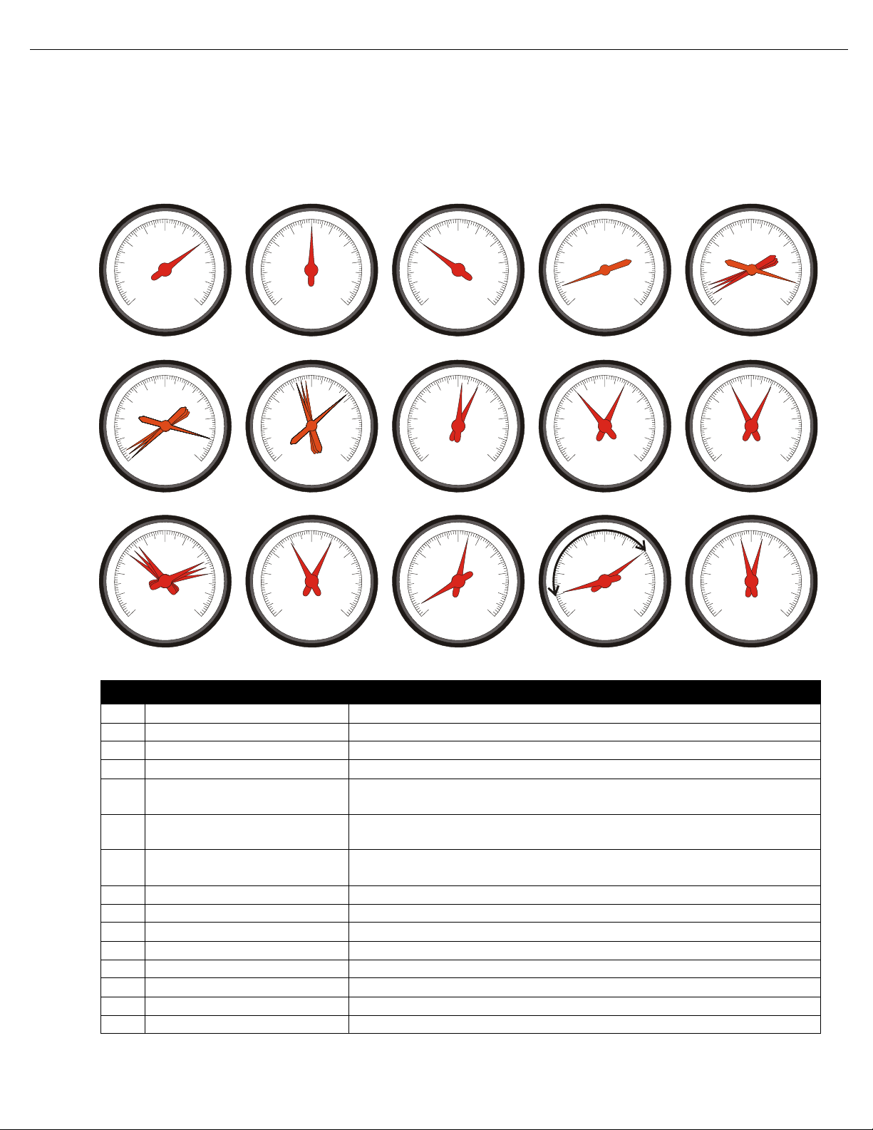
Intake Manifold Vacuum Testing
Test Procedures 1. Install a vacuum gauge to a good intake manifold source (usually
2. Observe the vacuum gauge while operating the engine over a
Test Results
1. A steady vacuum reading between 14 and 19in. Hg. (47-64 kPa)
2. A vacuum reading below 14 in. Hg. (47 kPa) at idle, indicates an
3. Possible causes of low intake manifold vacuum are late ignition
4. If the gauge fluctuates at idle, possible causes are sticking or leak-
5. If the gauge fluctuates at idle but smooths out as engine RPM
6. If the gauge fluctuates more with increases engine RPM, check for
7. If the vacuum gauge fluctuates regularly with each engine cycle,
at the PCV valve port), following the gauge manufacturer’s instructions. Start and warm up the engine.
range of engine speeds.
at idle indicates an engine in good mechanical condition.
engine that is not developing enough vacuum. Further testing for
base mechanical problems is needed.
timing, low compression, poor engine sealing, leaks at vacuum
lines and connections or bad MAP sensor.
ing valves, or an ignition miss.
increases, check for bad valves or camshaft.
weak or broken valve springs, bad valves, ignition miss, or a leaking head gasket.
check for a bad valve.
6 VPA 7746872 English 2006-10
Page 11
General Information
10
15
10
15
30
15
30
10
15
25
30
10
10
15
30
15
25
10
25
15
20
30
15
20
30
30
20
25
10
25
30
10
O
8. If the vacuum reading drops steadily as engine RPM increases,
check the exhaust system between the engine and vertical drive
for restrictions.
9. See table and chart below and on the following page for more
information.
15
10
5
0
10
5
0
20
25
30
In./Hg.
15
20
25
30
In./Hg.
15
10
5
0
10
5
0
20
25
30
In./Hg.
15
20
25
30
In./Hg.
15
10
5
0
10
5
0
20
25
30
In./Hg.
15
20
25
30
In./Hg.
15
10
5
0
10
5
0
20
25
30
In./Hg.
15
20
25
30
In./Hg.
FGH I
15
10
5
0
20
25
30
In./Hg.
15
10
5
0
20
25
30
In./Hg.
15
10
5
0
20
25
30
In./Hg.
15
10
5
0
20
25
30
In./Hg.
15
10
5
0
20
25
30
In./Hg.
EABCD
15
10
5
0
20
25
30
In./Hg.
J
15
10
5
0
20
25
30
In./Hg.
K
Pos Condition Reading
A Normal at Idle 14-19 in. Hg. (47-64 kPa)
B Late Ignition Timing 11-17 in. Hg. (37-57 kPa)
C Late Valve Timing 8-15 in. Hg. (27-50 kPa).
L
MN
D Intake Leak Low but steady reading
E Normal Acceleration Drops to 2 then rises to 25 when throttle is rapidly increased and
decreased.
F Worn Rings Drops to 0, then rises to 22 when throttle is rapidly increased and
decreased
G Sticking Valve(s) Normally steady, intermittently flicks downward approx. 4 in. Hg. (13 kPa)
from highest level.
H Leaking Valve Drops 2 in. Hg. (6 kPa) from highest reading.
I Burned or Warped Valve Evenly spaced down-scale flicker approximately 5 in. Hg (17 kPa).
J Worn Valve Oscillates Approximately 4 in. Hg. (13 kPa).
K Weak Valve Springs Violent oscillations as RPM increases.
L Improper Idle Mixture Floats slowly between 13-17 in. Hg. (44-57 kPa)
M Restricted Exhaust Normal when first started. Drops to approx. 0 as RPM increases
N Head Gasket Leak Floats between 5-20 in. Hg. (17-68 kPa)
O Defective Ignition Component Slight float between 14-16 in. Hg. (47-54 kPa)
VPA 7746872 English 2006-10 7
Page 12

General Information
Gasoline Requirements
DANGER!
Gasoline is extremely flammable and highly explosive
under certain conditions. Always stop engine and do not
smoke or allow open flames or sparks near the boat when
refuelling gas tanks. When filling the gas tank, ground the
tank to the source of gasoline by holding the hose nozzle
firmly against the side of the deck filler plate, or ground it
in some other manner. This action prevents static electricity buildup which could cause sparks and ignite fuel
vapors.
USE ONLY UNLEADED FUEL. Use lead-free gasoline with the fol-
lowing minimum or higher octane specification:
Inside the U.S.: (R+M)/2 (AKI) = 87
Outside the U.S.: (RON) = 90
If fuels with 89 AKI pump posted (93 RON) octane number or higher
are used an increase in power can be expected with EFI models.
Premium fuels contain injector cleaners and other additives that protect the fuel system and provide optimum performance.
Gasoline Containing Alcohol
Caution!
Engine damage resulting from the use of gasoline with
octane 86 AKI (89 RON) and lower is considered misuse of
the engine and will void the engine warranty. Vol vo Pe nta
suggests the use of 89 AKI or higher fuels. These fuels
have additives that are beneficial to maximum engine performance and long life of service components.
To prevent gum formation and corrosion in the fuel system, use a
Marine Fuel Stabilizer in the gasoline.
Many brands of gasoline being sold today contain alcohol. Two commonly used alcohol additives are Ethanol (ethyl alcohol) and Methanol
(methyl alcohol).
Caution!
Do not use any gasoline which contains Methanol (methyl
alcohol).
See the boat’s Operators Manual to determine if the boats fuel system
is compatible with alcohol blended fuels. If it is, your engine may use
gasoline blended with no more than 10% Ethanol (ethyl alcohol) meeting the minimum octane specification. Do not use any gasoline which
contains METHANOL (methyl alcohol).
Continued use of METHANOL (methyl alcohol) fuel will cause serious
damage to the fuel system.
If you use gasoline containing alcohol, be aware of the following:
8 VPA 7746872 English 2006-10
Page 13

Crankcase Oil
General Information
• ïThe engine will operate leaner. This may cause engine problems such as vapor lock, low speed stalling, or hard starting.
• ïAlcohol blended fuels attract and hold moisture. Moisture can
cause fuel tank corrosion. Inspect fuel tanks at least annually.
Replace corroded or leaking fuel tanks.
• ïFrequently inspect non-metallic parts of fuel system and
replace if excessively stiff, deteriorated or leaking.
Fuel leakage can contribute to a fire and/or explosion.
Initial factory fill is a high quality motor oil for API Service SJ. During the
break-in period (20 hours), frequently check the oil level. Somewhat
higher oil consumption is normal until piston rings are seated. The oil
level should be maintained in the safe range between the Add and Full
marks on the dipstick. This range represents approximately 1 litre (1
quart). If it is necessary to add or change the motor oil, use a quality oil
with API service category SJ.
At the end of the break-in period (20 hours), change the crankcase oil
and replace the oil filter. Refer to Lubrication and Inspection Chart
for recommended oil change intervals.
Draining and Filling the Engine
Crankcase
NOTE! The use of multi-viscosity oils, such as 10W-30 or 10W-40,
is not recommended.
If using Volvo Penta Premium Synthetic Engine Oil, drain and refill
crankcase every 200 hours of operation or once a year, whichever occurs first.
If using oil other than Volvo Penta Premium Synthetic Engine Oil, drain
and refill crankcase every 100 hours of operation or once a year, whichever occurs first.
DANGER!
To prevent fire and explosion, always make sure engine
compartment is free of gasoline fumes before using any
spark-producing tools such as the electric drill motor
used with oil withdrawal pump kit.
Check the motor oil level frequently with the dipstick. When oil is to be
changed, remove dipstick and withdraw oil from crankcase through
withdrawal/dipstick tube. The oil withdrawal tube is provided so oil does
not have to be drained into the bilge. Withdraw oil with a suction pump.
Fill the crankcase to the specified capacity with a quality motor oil labelled for service category SH. When changing motor oil, select from
the following chart the SAE viscosity that matches the temperature
range in which the boat will be operated. If it is necessary to add motor
VPA 7746872 English 2006-10 9
Page 14
General Information
oil, use motor oil of the same viscosity.
Table 2: Temperature Viscosity Recommendations
If the lowest Anticipated
Temperature is:
32° F (0° C) and above SAE 30
0° F (-18° C) to 32° F (0° C) SAE 20W-20
Below 0° F (-18° C) SAE 10
NOTE! Disregard any reference to multi-viscosity oil printed on
engine. Such reference is intended for automotive use
only and not marine application.
Caution!
Do not fill above full mark. Overfilling results in high operating temperatures, foaming (air in oil), loss of power, and
overall reduced engine life.
Table 3: Crankcase Capacities
Model With Filter
4.3GXi/OSi 5.0 qts. (4.7 liters)
The Following SAE Viscosity
Oils are Recommended
Sterndrive
Off-Season Storage
5.0GXi/OSi 5.5 qts. (5.2 liters)
5.7Gi/GXi/OSi/OSXi 5.5 qts. (5.2 liters)
8.1Gi/GXi 9.0 qts. (8.5 liters)
Inboards
5.7GiI/GXiI 5.5 qts. (5.2 liters)
8.1GiI/GXiI 9.0 qts. (8.5 liters)
Oil Filter Replace the oil filter whenever the motor oil is changed. This filter is a
self-contained, screw-on type. To remove, unscrew filter canister
counterclockwise and discard. When attaching a new filter, be sure the
gasket is lightly lubricated with motor oil. Hand tighten only, run engine
and check for leaks. Do not run engine without supplying cooling
water. See Parts Catalog for model and filter requirements.
Maintain the level with Volvo Penta Power Trim/Tilt & Steering Fluid.
Approved power steering fluids such as GM power steering fluid or
Dexron II automatic transmission fluid can also be used. Do not overfill
the pump reservoir.
There are nine steps that must be completed for Off-Season Storage
Preparation
10 VPA 7746872 English 2006-10
Page 15

General Information
When gasoline engines are removed from service for long periods (2
months or more), it is important that they are correctly stored or protected (internally). Today’s gasoline blends are not as stable as in the
past and consideration must be given if the fuel will not be used within
a short time or if the engine is being placed in storage. Failure to properly stabilize the fuel can damage fuel system components and is not
considered as warrantable.
Boat manufacturers should follow the gasoline storage mixture
section for testing prior to shipment.
Note! Volvo Penta has discontinued the fuel stabilizer #3855832,
a suitable replacement can be purchased locally at most
automotive supply stores.
Limited Use If the vessels fuel within the tank(s) will not be consumed within a 30-
day period from the time of filling, a gasoline fuel stabilizer must be
added as per the manufacturers instructions. This will help prevent the
fuel from breaking down and causing reduced engine performance or
damage from uncontrolled combustion.
Storage If the boat is being placed into storage, a gasoline fuel stabilizer must
be added to the tank(s) as per the manufacturers instructions. The
amount of stabilizer required is determined by the quantity of fuel and
the length of time it will be placed in storage. The maximum period that
fuel can be stabilized is six months due to limitations of the stabilizers
and fuels.
DANGER!
Any fuel leakage should be corrected immediately to prevent possible fire and/or explosion.
Caution!
Do not run engine out of fuel or run the electric fuel
pumps dry more than 10 seconds. Running the electric
fuel pumps dry will cause fuel pump damage.
Prepare a storage mixture In addition to stabilization of the fuel, it is highly desirable to have the
valves and cylinders coated with a light film of oil previously accomplished through fogging. Today’s fuel injection manifolds are designed
with a complex air channel design that will not allow the traditional fogging oils to be injected past the throttle plate while running. The oil will
get stuck in the plenum and never reach the cylinders. Together with
the stabilizer, two-cycle motor oil can be added to a fuel mixture for
stabilization purposes.
• Using an outboard motor six-gallon fuel tank, add two-cycle
motor oil at a ratio of 50:1 (one pint to 6 gallons) and stabilizer
at one ounce per gallon (unless stated otherwise on the manufacturers label). Mix well.
• Disconnect boat fuel line at engine fuel pump. Attach the storage mixture fuel tank.
• Connect a suitable engine flush device if the boat is not in the
water.
VPA 7746872 English 2006-10 11
Page 16

General Information
Electric Fuel Pumps and Fuel Cells Regardless of the ratio of fuel stabilizer to fuel we use, the maximum
• Run the engine on the storage mixture for approximately 5 minutes at 1500 RPM. This will ensure that all fuel system and
internal engine components are thoroughly protected. Do not
operate the engine above 1500 RPM as the water pump
demand may exceed the supply, damaging the pump.
• Reduce the engine speed to idle and stop the engine.
• Reconnect the fuel fitting and check for fuel leaks.
recommended storage time for gasoline, according to STA-BIL, is six
months. During final assembly testing at our Lexington factory, each
engine is run on a fuel mix that is stabilized. Each engine is shut off
without running the fuel pumps dry and the fuel system is sealed to
prevent damage. With the delay in time between the product getting
installed in a boat, shipped to you, sold and finally delivered; the sixmonth time frame can easily be exceeded.
Since delivering a quality, dependable product is one of our highest
goals; we work closely with our suppliers to identify the root cause of
failure on any parts returned for warranty credit. While there are certainly legitimate failures of fuel pumps, the major portion of them are
returned to us due to varnished fuel from long term storage. We would
like to offer some advice on dealing with these issues.
Stuck Pumps If a fuel pump appears stuck and will not operate, you may try briefly
reversing the polarity to the pump to turn it in the opposite direction.
You should disconnect the electrical plug of one pump at a time on the
fuel cell to determine which pump might have a problem.
Noisy Fuel Pumps Electric pumps will often cavitate and become noisy if they are starving
for fuel. On carbureted engines or low-pressure fuel cell pumps, check
the fuel supply, quality of the fuel hose, anti-siphon valve, and filter
before replacing the fuel pump.
A noisy high-pressure pump on a fuel cell may indicate a low fuel level
in the reservoir. Check the fuel supply and low pressure pump operation to be sure the reservoir is receiving the correct volume of fuel. The
same information would apply to engines with the earlier vapor separator tank design.
This information may help prevent the needless replacement of pumps
in many cases and reduce the repair time for the boat owner.
Change Motor Oil and Oil Filter • Engine should first be operated under load until oil is thoroughly
warmed up. If oil is allowed to warm up before draining, a more
complete draining will be accomplished. In addition, accumulated impurities will be held in suspension by the oil and be
removed during draining operation.
• Remove motor oil by siphoning it out of oil withdrawal tube. Follow the procedure under Draining and Filling the Engine
Crankcase.
• Install a new oil filter and fill crankcase with recommended oil.
Caution!
12 VPA 7746872 English 2006-10
Page 17
Change Sterndrive Lubricant
Drain Cooling System
D
C
A
B
23681
General Information
Sterndrive must be submerged in water or an accessory
flushing adaptor must be used while operating engine.
When using a flushing adaptor, remove propeller before
starting engine to prevent accidental contact with rotating
propeller.
• With sterndrive in full down position, run engine at a fast idle for
a few minutes to distribute clean oil through engine.
• Shut off engine and check oil level. Check oil filter gasket for
leaks. Add oil if necessary to bring oil level up to, but not over,
the full mark.
Drain and refill with fresh Volvo Penta GL-5 Synthetic Gear Lubricant
or Mobilube 1 SHC Fully Synthetic SAE 75W-90 (meeting or exceeding MIL-L-2105C or D, API GL-4 or 5) gear lubricant. Refer to Vertical
Drive Service Manual.
When draining the cooling system, raise or lower the bow of the boat
to position the engine in a level horizontal plane. This will provide complete drainage of the engine block and manifolds. If the bow is higher
or lower that the stern, some water may be trapped in the engine block
or manifolds.
Improper or incomplete draining may result in freeze damage to the
engine, manifolds, sterndrive, or other components. Freeze damage is
not covered under Volvo Penta’s Limited Warranty.
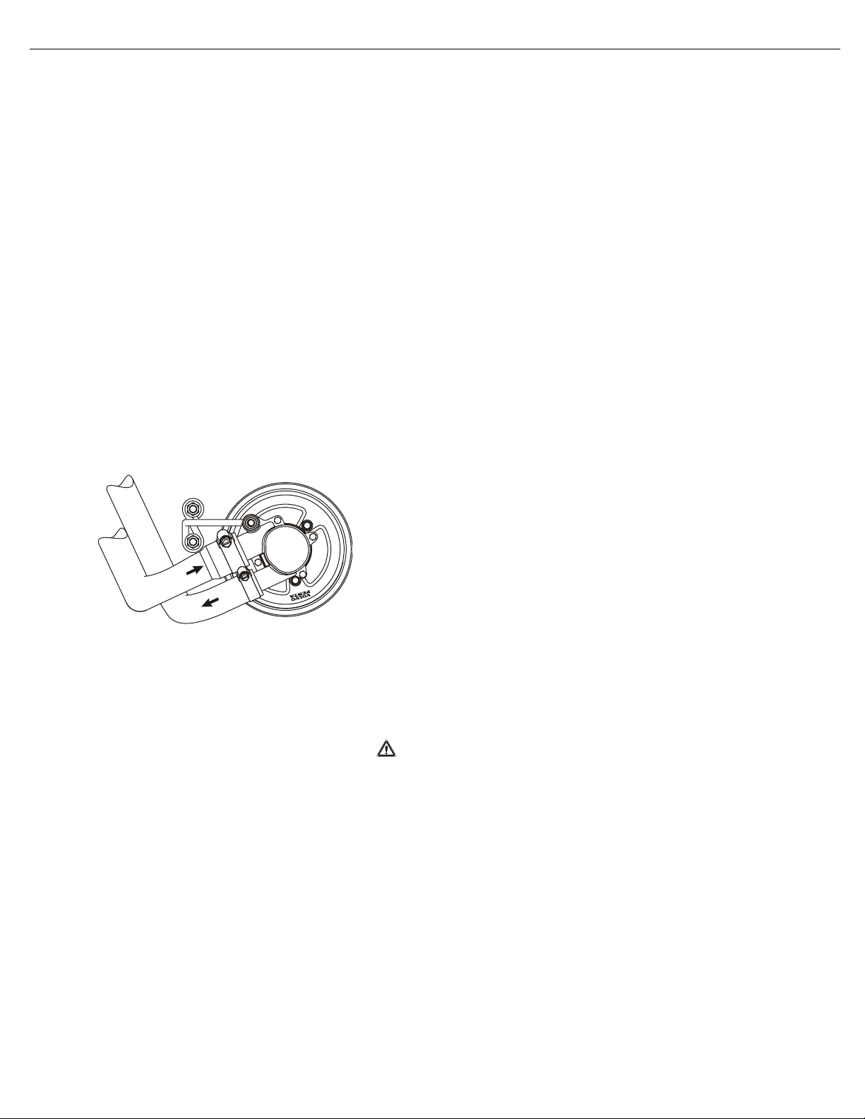
4.3GXi, 4.3OSi
Front
Port
1. Remove inlet (A) and outlet (B) hoses from raw water pump and
rotate engine with starter 1-2 revolutions. If engine starts to run,
shut off immediately.
Caution!
Do not run engine without water. If engine starts with the
water intake hose disconnected, shut off immediately.
Allowing the engine to run without water will damage the
engine and cooling components.
2. Disconnect the small water by-pass hose at the top of the thermo-
stat housing.
3. Disconnect and drain large hose at the circulation pump.
4. Disconnect the fuel cell water discharge hose. Lower the hose into
the bilge to allow draining. Blow out and remaining water with
compressed air. Reconnect after draining is complete.
5. Remove cylinder block drain plug. Clear hole with small wire to
ensure complete drainage.
6. Remove exhaust manifold drain plug. Clear hole with small wire to
ensure complete drainage.
VPA 7746872 English 2006-10 13
Page 18

General Information
Starboard 7. Remove cylinder block drain plug. Clear hole with small wire to
ensure complete drainage.
8. Remove exhaust manifold drain plug. Clear hole with small wire to
ensure complete drainage.
9. Reinstall drain plugs after draining is complete to keep the threads
of the drain holes from corroding. It will be difficult to install the
drain plugs if the plugs are left out over the winter.
5.0GXi, 5.0OSi, 5.7Gi, 5.7OSi, 5.7GXi, 5.7OSXi, 5.7GiI-F, 5.7GXiI-G
Front
Port
Starboard
1. Remove inlet (A) and outlet (B) hoses from raw water pump and
rotate engine with starter 1-2 revolutions. If engine starts to run,
shut off immediately.
Caution!
Do not run engine without water. If engine starts with the
water intake hose disconnected, shut off immediately.
Allowing the engine to run without water will damage the
engine and cooling components.
2. Disconnect and drain large hose at the circulation pump.
1. Remove cylinder block drain plug. Clear hole with small wire to
ensure complete drainage.
2. Remove exhaust manifold drain plug located at the rear of the
exhaust manifold. Clear hole with small wire to ensure complete
drainage.
1. Remove cylinder block drain plug. Clear hole with small wire to
ensure complete drainage.
2. Remove exhaust manifold drain plug located at the rear of the
exhaust manifold. Clear hole with small wire to ensure complete
drainage.
3. Reinstall drain plugs after draining is complete to keep the threads
of the drain holes from corroding. It will be difficult to install the
drain plugs if the plugs are left out over the winter.
8.1Gi, 8.1GXi, 8.1OSi, 8.1GiI-G, 8.1GXiI-F
Front
1. Remove inlet (A) and outlet (B) hoses from raw water pump and
rotate engine with starter 1-2 revolutions. If engine starts to run,
shut off immediately.
Caution!
Do not run engine without water. If engine starts with
intake hose disconnected, shut off immediately. Allowing
the engine to run without water will damage the engine
and cooling components.
2. Disconnect and drain large hose at the circulation pump.
Port
1. Remove cylinder block drain plug. Clear hole with small wire to
ensure complete drainage.
14 VPA 7746872 English 2006-10
Page 19

General Information
2. Remove exhaust manifold drain plug located at the front of the
port exhaust manifold, behind the power steering pump. Clear
hole with small wire to ensure complete drainage.
Starboard
1. Remove cylinder block drain plug. Clear hole with small wire to
ensure complete drainage.
2. Remove exhaust manifold drain plug located at the rear of the
exhaust manifold. Clear hole with small wire to ensure complete
drainage.
3. Reinstall drain plugs after draining is complete to keep the threads
of the drain holes from corroding. It will be difficult to install the
drain plugs if the plugs are left out over the winter.
Preparation for Boating After Storage
1. Install all drain plugs if they were left out during storage. Install
cooling hoses and clamps. Check condition of hoses, manifold
end caps and clamps. Connect hoses to engine and tighten
clamps securely. Install boat drain plug, if removed.
2. Remove the distributor cap and rotor. Wipe the inside of the dis-
tributor cap dry with a clean cloth and spray with Corrosion Spray.
Replace the rotor and cap.
3. Clean the battery terminals. With the ignition switch in the "OFF"
position, install the battery and attach the battery cables. Spray
terminals with Corrosion Spray.
4. Open the fuel shut-off valve (if so equipped) and check all fuel
line connections for leaks.
5. Check the flame arrestor and clean if necessary. Reinstall, make
sure all parts are in place and tighten nut securely.
Warning!
Do not place fingers in the throttle body on electronic
throttle equipped engines. The throttle plate has a powerful motor that can cause severe injury if the ignition energized.
6. Make a thorough check of the boat and engine for loose or miss-
ing nuts and screws. Pump the bilge dry and air out the engine
compartment.
Danger!
To prevent a possible explosion, operate the blower as
recommended by the boat manufacturer before starting
engine. If the boat is not equipped with a bilge blower,
open engine cover or hatch prior to starting and leave
open until after engine is running.
If operating boat in water, tie boat securely to dock to prevent forward or backward movement.
When using a flushing adaptor, remove the propeller
before starting engine to prevent accidental contact with
rotating propeller.
VPA 7746872 English 2006-10 15
Page 20

General Information
Engine Break-in
7. Test run engine: Launch boat or use a flushing adaptor installed
on Sterndrive.
Caution!
Do not start engine out of water unless using a flushing
adaptor. Always turn water on before starting engine.
Control water pressure as full water pressure may cause
damage to supply pump and engine.
8. With engine compartment open, start the engine. Monitor the volt-
meter, oil pressure and water temperature gauges frequently to be
sure all systems are operating properly. Check for fuel, oil, and
water leaks.
All engines have been run for a short period of time as a final test at
the factory. You must follow the Engine Break-In procedure during the
first 20 hours of operation to ensure maximum performance and longest engine life.
NOTE!
To ensure proper lubrication during the break-in period,
do not remove factory break-in oil until after the 20-hour
break-in is completed.
First Two Hours For the first five to ten minutes of operation, operate engine at a fast
idle (above 1500 RPM). After engine has reached operating temperature, momentarily reduce engine speed, then increase engine speed,
to assist break-in of piston rings and bearings.
During the remaining first two hours of operation, accelerate boat onto
plane quickly and bring throttle back to maintain a planing attitude.
During this period, vary the engine speed frequently by accelerating to
approximately three-fourths throttle for two to three minutes, then back
to minimum planing speed. Maintain planing attitude to avoid excessive engine load.
DO NOT RUN ENGINE AT A CONSTANT RPM FOR PROLONGED
PERIODS OF TIME DURING THE BREAK-IN PERIOD.
Next Eight Hours During next eight hours, continue to operate at approximately three-
fourths throttle or less (minimum planing speed). Occasionally reduce
throttle to idle speed for a cooling period. During this eight hours of
operation it is permissible to operate at full throttle for periods of less
than two minutes.
DO NOT RUN ENGINE AT A CONSTANT RPM FOR PROLONGED
PERIODS OF TIME DURING THE BREAK-IN PERIOD.
Final Ten Hours During the final ten hours of break-in, after warming engine to operat-
ing temperature, it is permissible to operate at full throttle for five to ten
minutes at a time. Momentarily reduce then increase engine speed to
assist break-in of rings and bearings. Occasionally reduce engine
speed to idle to provide cooling periods.
DO NOT RUN ENGINE AT A CONSTANT RPM FOR PROLONGED
PERIODS OF TIME DURING THE BREAK-IN PERIOD.
16 VPA 7746872 English 2006-10
Page 21

General Information
During break-in period, be particularly observant during initial running
of engine, as follows:
1. Check crankcase oil level frequently. Maintain oil level in safe
range, between “add” and “full” marks on dipstick.
NOTE! If you have a problem getting a good oil level reading on
dipstick, rotate dipstick 180° in tube.
2. Watch oil pressure gauge. If indicator fluctuates whenever boat
attitude (i.e. turning, climbing on plane, etc.) is changed, it may be
the oil pickup screen is not covered with oil. Check crankcase dipstick, and add oil to crankcase if required. DO NOT OVERFILL. If
oil level is correct and condition still exists, check for possible
gauge or oil pump malfunction.
NOTE! Oil pressure will rise as RPM increases, and fall as RPM
decreases. In addition, cold oil will generally show higher
oil pressure for any specific RPM than hot oil. Both of
these conditions reflect normal engine operation.
3. Watch engine temperature indicator to be sure there is proper
water circulation.
Caution
Failure to follow the break-in procedure will void the
engine warranty.
At end of break-in period (20 hours), change the motor oil and replace
oil filter. Fill crankcase with recommended motor oil, See “Crankcase
Oil” on page 9.
Operation After Break-in After break-in, the engine can be operated at any RPM from idle to full
throttle. However, cruising at 3600 RPM or less saves fuel, reduces
noise, and prolongs engine life.
When starting a cold engine, always allow engine to warm up gradually. Never run engine at full throttle until engine is thoroughly warmed
up. Be sure to check oil level frequently during the first 50 hours of
operation, since oil consumption will be high until piston rings are
properly seated.
Submerged Engine Remove engine from water as quickly as possible.
It is imperative that all water is removed from the engine and immediately lubricate all internal parts. All electrical devices must also be
dried and inspected for water damage. Delay in completing these
actions may allow extensive engine damage.
Frequently check engine compartment for gasoline fumes and excessive water accumulation; water depth in bilge should be kept well
below flywheel housing.
20-Hour Check
1. Change engine oil and oil filter.
2. Check power trim/tilt reservoir for proper fluid level.
3. Change fuel filter/water separator.
4. Check flame arrestor for proper mounting, cleanliness or damage.
5. Start engine and check complete fuel system for leaks.
VPA 7746872 English 2006-10 17
Page 22
General Information
3
8
6
0
0
9
1
6. Lubricate steering cable ram with Volvo Penta grease. Check
power steering pump reservoir for correct fluid level on models
equipped with power steering. Failure to properly lubricate the
steering system could lead to loss of steering control.
7. Check shift system for proper adjustment and operation.
8. Inspect exhaust system. Tighten all hose clamps, and check for
leaks.
9. Check tension on all drive belts.
10. Check all engine mount screws for tightness.
11. Check for any deficiencies, malfunctions, signs of abuse, etc. Cor-
rection of any problems at this time will prevent the worsening of a
minor problem and help ensure a trouble-free boating season.
12. Check oil level in Sterndrive and add as necessary with GL-5 Syn-
thetic Gear Lubricant or Mobilube 1 SHC Fully Synthetic SAE
75W-90 (meeting or exceeding MIL-L-2105C or D, API GL-4 or 5)
gear lubricant.
13. Make sure engine can achieve maximum rated RPM. See engine
specifications.
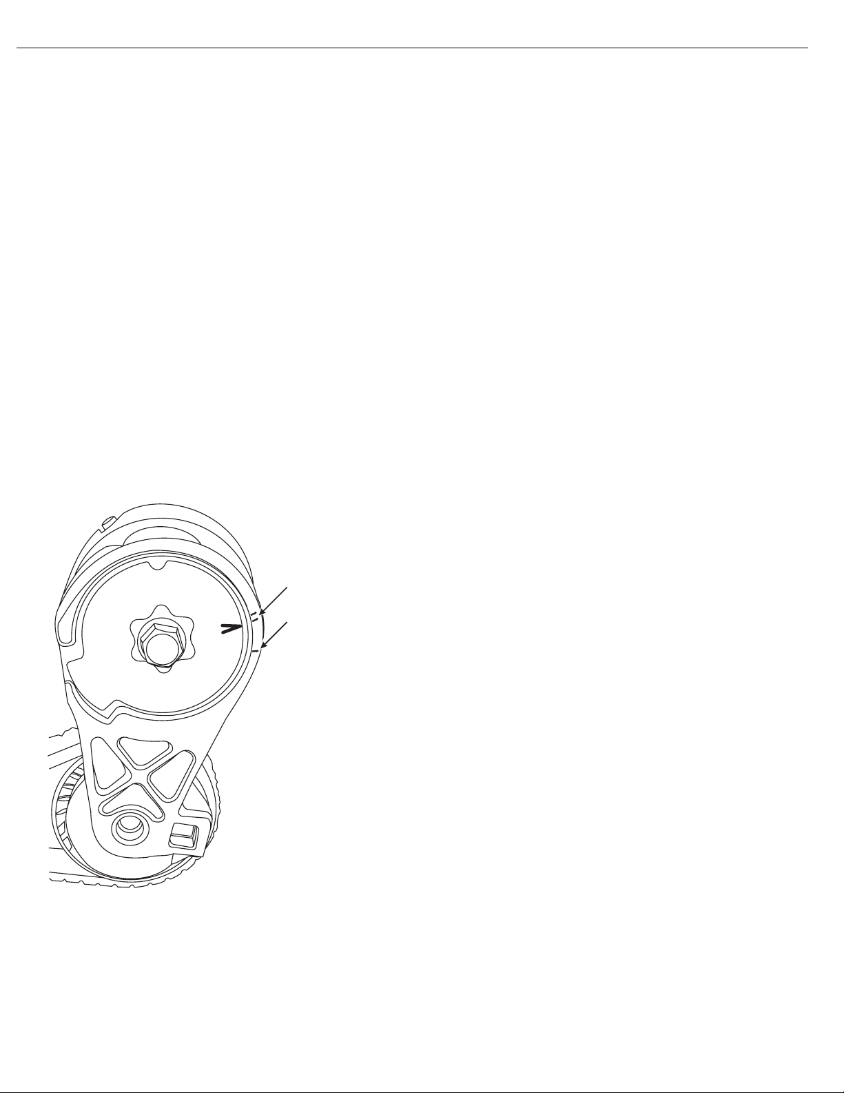
Belt Tension
22902 Serpentine belts are tensioned automatically and do not require
adjustment. Replace when the tension indicator lines up with the single line on the housing (A).
The Volvo Penta serpentine belts are for heavy-duty marine use. DO
NOT replace with automotive belts.
A
B
Positive Closed-Type Ventilation System
5.0L and 5.7L engines only A malfunctioning closed crankcase ventilation system may be indi-
cated by loping or rough engine idle. Do not attempt to compensate for
this idle condition by disconnecting the crank-case ventilation system
and making adjustments. The removal of the crankcase ventilation
system from the engine will adversely affect fuel economy and engine
18 VPA 7746872 English 2006-10
Page 23

General Information
ventilation with resultant shortening of engine life. To determine
whether loping or rough idle condition is caused by a malfunctioning
crankcase ventilation system, perform the following tests.
NOTE! 8.1 engines have an internal crankcase ventilation system
and have no serviceable components.
NOTE! 4.3 engines do not have a PCV valve. The crankcase venti-
lation is provided by a fixed orifice located in the port
valve cover and connected by a hose to the intake manifold.
With Engine Idling
With Engine Stopped Remove PCV valve from its mounting and shake it. A metallic clicking
Servicing PCV Valve Caution!
1. Remove PCV valve from its mounting, but leave vacuum inlet side
connected to hose. If the valve is functioning properly and not
plugged, a hissing noise will be heard as air passes through valve.
A strong vacuum will be felt when a finger is placed over valve
inlet. Check for vacuum leaks in hose line and at all connections.
2. Reinstall PCV valve, then remove crankcase air inlet hose at
flame arrestor connection. Loosely hold a small piece of stiff paper
(such as a 3 x 5 memo card or parts tag card) over opening at end
of inlet hose. After a minute or so, (to allow crankcase pressure to
lower) the piece of paper should be sucked against hose opening
with a noticeable force.
noise should be heard, indicating that valve parts are free, and not
sticking.
If ventilation system passes these two tests, it can be considered functionally OK, and no further service is required. If it fails either test,
replace PCV valve and repeat Engine Idling Test.
If system still does not pass test, clean ventilation system hoses and
all passages to induction system in accordance with established procedures.
Do not attempt to clean crankcase ventilation regulator
valve. It should be replaced.
Clean crankcase ventilation system connection(s) on intake manifold
by probing with a flexible wire or bottle brush. Clean hoses, tubes and
associated hardware with a low-volatility, petroleum-base solvent and
dry with compressed air.
Troubleshooting - System Isolation
The following is to help you isolate a malfunction of one or possibly
several systems. After determining which systems are related to the
VPA 7746872 English 2006-10 19
Page 24

General Information
Engine Does not Start
malfunction, refer to the individual system troubleshooting charts to
isolate the specific cause.
Engine should crank at specified RPM. If not, check for
1. Discharged or dead Battery
Cranking System
2. Loose or corroded connections
3. Cranking System Troubleshooting Chart in the Elec-
trical Ignition/ Fuel Service Manual
Ignition System Must have good spark at spark plugs. If not, check the:
1. Distributor Cap
2. Coil and spark plug leads
3. Ignition timing
4. Automatic spark advance
5. Appropriate Ignition Troubleshooting Chart in the
Electrical/Ignition/Fuel Service Manual.
Fuel System
1. Fuel Tank, valves, and lines
2. Fuel pump and filter
3. Boat Fuel System Troubleshooting Chart
4. Engine Fuel System Troubleshooting Chart
Engine Runs Improperly Check the following:
1. Compression
2. Ignition system
3. Fuel and injection system
4. Lubrication system
5. Cooling System
6. Sterndrive and propeller
7. PCV Valve
8. Engine Troubleshooting Guides
Engine Troubleshooting Guides
These guides were written to help you trace the symptoms of the trouble to the source, without having to read through and prove every possibility. Much of the information here will be familiar to well informed
mechanics.
Also, many factors will seem insignificant but when you think of it, usually the toughest problem to troubleshoot is caused by the smallest
error. The greatest aid to solving a service problem is information.
Start gathering information from the boat operator and write it on his
job card or work ticket. Find out pertinent facts, such as:
• When did this trouble start?
• How was the boat loaded?
• Did the trouble occur suddenly, or start gradually?
Analyze this information and try to match it to similar situations you
have experienced in the past. Keep in mind the fundamental rules:
20 VPA 7746872 English 2006-10
Page 25

General Information
• COMPRESSION - Mixture inducted into cylinder and compressed.
• SPARK - Proper intensity at the proper time.
• FUEL - Proper mixture of air and fuel.
These are very old rules, but necessary for the engine to run. Use
these charts and the service information they refer to. Do not try to
remember tolerances, settings, measurements, etc., as they are written in the service manual. Leave your mind free to analyze the problem.
Following is a list of the troubleshooting guides which may be found on
the pages indicated.
Engine Will Not Crank . . . . . . . . . . . . . . . . . . . . . . . . . . . . . . . . . . . . . page 21
Engine Cranks, But Will Not Start . . . . . . . . . . . . . . . . . . . . . . . . . . . . page 21
Hard Starting - Cold Engine . . . . . . . . . . . . . . . . . . . . . . . . . . . . . . . . page 22
Hard Starting - Hot Engine . . . . . . . . . . . . . . . . . . . . . . . . . . . . . . . . . page 22
Engine Runs Rough . . . . . . . . . . . . . . . . . . . . . . . . . . . . . . . . . . . . . . page 23
Engine Will Not Crank
Starter Circuit - Check: • Battery condition: weak, dead, sulfated, bad cells
Engine Noises and Vibrations . . . . . . . . . . . . . . . . . . . . . . . . . . . . . . . page 23
Engine Overheats . . . . . . . . . . . . . . . . . . . . . . . . . . . . . . . . . . . . . . . . page 24
Engine Dies Out . . . . . . . . . . . . . . . . . . . . . . . . . . . . . . . . . . . . . . . . . page 24
Engine Won’t Reach Operating RPM . . . . . . . . . . . . . . . . . . . . . . . . . page 25
Defective Engine Lubricating System . . . . . . . . . . . . . . . . . . . . . . . . . page 25
Low Battery Voltage After Short Storage. . . . . . . . . . . . . . . . . . . . . . . page 26
• Battery cables for loose or corroded connections
• Shorted or open ignition switch
• Starter motor and solenoid for shorts, grounds or open circuits
• Starter assist solenoid/starter relay
• Circuit breakers
• Wiring from battery to ignition switch
•See Electrical/Ignition/Fuel Service Manual
Engine Cranks, But Will Not Start
Ignition Circuit - Check: • Primary circuit wiring from ignition switch to ignition coil/ignition
module
• Secondary circuit wiring from coil to spark plug
• Spark plugs for proper gap, fouling, burned electrodes, cracked
or dirty insulator
•See Electrical/Ignition/Fuel Service Manual
• Low battery voltage
VPA 7746872 English 2006-10 21
Page 26

General Information
Fuel System - Check: • Quantity and condition of fuel in boat tank
Cylinder Compression - Check • Conduct test following procedure in this section, and compare
Hard Starting - Cold Engine
• Operation and flow capacity of boat anti-siphon valve
• Fuel tank vent is unrestricted
• Fuel tank pick-up screen is clean
• Correct diameter/unrestricted boat fuel lines
• Fuel shutoff and multiple tank valves are open and operating
properly
• Fuel pump vent hose for signs of fuel or oil that would indicate a
fuel pump failure.
• Fuel pump/relay/circuit breaker operation
• External fuel filter
• See Electrical/Ignition/Fuel System Service Manual
readings to Compression Limit Chart.
Has Engine Always Done This?
Check:
Was Engine Used For A Long Time?
Check:
Is This A New Condition? Check:
Hard Starting - Hot Engine
Has Engine Always Done This?
Check:
Ask these questions first:
1. Fuel tank antisiphon valve (if equipped)
2. Fuel lines for obstructions
3. For debris inside fuel tank
4. See Electrical/Ignition/Fuel System Service Manual
1. For clean external fuel filters
2. Water in fuel due to condensation
3. Fuel quality deterioration
4. See Electrical/Ignition/Fuel System Service Manual
1. Fuel tank antisiphon valve (if equipped)
2. Fuel system for leaks, dirt, or obstructions
3. Engine and ignition system
4. See Electrical/Ignition/Fuel System Service Manual
Ask these questions first:
1. Fuel tank antisiphon valve (if equipped)
2. See Electrical/Ignition/Fuel System Service Manual
Is This A New Condition? Check:
1. Brand, type or octane of fuel
2. Spark plugs
3. Water in fuel
4. Condition of battery and cables
5. Starter motor for overheat damage
22 VPA 7746872 English 2006-10
Page 27

General Information
Did Engine Refuse To Start After
Being Run? Check:
Ignition coil(s)/ignition module
Engine Runs Rough
If At Slow Speed - Check: 1. Fuel tank antisiphon valve (if equipped)
If At High Speed - Check:
1. Ignition system primary circuit
2. Engine timing
3. Fuel tank antisiphon valve (if equipped)
4. See Electrical/Ignition/Fuel System Service Manual
2. Idle speed
3. Engine timing and spark plugs
4. Fuel pressure
5. Water or contaminants in fuel
6. Manifold vacuum leak
7. See Electrical/Ignition/Fuel System Service Manual
1. Air leak on suction side of fuel system
2. Too low octane fuel
3. Ignition system secondary circuit
4. Engine timing
Engine Noises and Vibrations
Valves - Hydraulic Lifters 1. Rapping only when starting (oil too heavy for prevailing weather,
Ignition System (Ping or Knock)
5. Fuel filter
6. Fuel pump pressure
7. Engine compression
8. Water or contaminants in fuel, water in cylinders
9. See Electrical/Ignition/ Fuel System Service Manual
varnish on lifter, oil needs to be changed)
2. Intermittent rapping (leakage at lifter check ball)
3. Idle noise (excessive leak down rate, faulty check ball seat)
4. Generally noisy (excessive oil in crankcase, stuck lifter plunger)
5. Loud noise at operating temperature (scored lifter plunger, fast
leak down rate, oil viscosity too light for prevailing weather or operating temperatures)
6. See appropriate Engine section
1. Incorrect spark plugs
2. Incorrect spark plug wire routing
3. Use higher octane fuel
4. See Electrical/Ignition/Fuel Service Manual
Cooling System
1. Supply pump
2. Loose belts, pulleys
VPA 7746872 English 2006-10 23
Page 28

General Information
3. See Cooling System section
Crankshaft Balancer or Flywheel
Engine Overheats
Mountings
Alternator
Sterndrive
1. Loose, broken or worn engine mounts
2. Loose lag screws holding mounts to stringer
3. Check engine alignment see Removing and Installing Engine sec-
tion
1. Loose bolt(s)
1. Loose pulley, worn bearings
2. Loose mounting bolts
1. Failed U-joints or gimbal bearing
2. Damaged internal drive components
3. Worn, bent or broken propeller hub or blades
4. Loose, worn or damaged engine coupler
1. Actual engine temperature by verifying with an accurate thermom-
eter
2. Gauge operation and wiring circuit
3. Sending unit operation and wiring circuit
4. Supply pump, circulating pump and belt(s)
5. Water intake screens for blockage
6. Thermostat
7. Water supply hoses
8. Engine timing
9. Water leaks on pressure side of supply pump
10. Air leaks on suction side of supply pump
11. Engine compression
Engine Dies Out
Loss Of, Or Out Of, Fuel - Check: 1. Fuel gauge operation and wiring
2. Fuel level in tank
3. Water or debris in fuel
4. Fuel pickup tube and screen blockage
5. Fuel tank vent blockage
6. Plugged fuel filter
7. Air leak on suction side of fuel system
8. Fuel leak on pressure side of fuel system
9. Inoperative, restricted or incorrectly sized anti-siphon valve
10. Boat fuel lines too small in diameter
11. Fuel pump pressure and suction
24 VPA 7746872 English 2006-10
Page 29

General Information
12. See Electrical/Ignition/Fuel System Service Manual
Loss Of Ignition - Check:
Engine Stops Or Dies Out Due To
Seizure - Check:
1. Primary and secondary ignition circuits
2. Ignition switch
3. Circuit breakers
4. Wiring between engine and dash
5. Main engine harness wiring
6. See Electrical/Ignition/Fuel Service Manual
1. Sterndrive for internal damage
2. Oil pressure gauge
3. Crankcase oil level
4. Water in engine or sterndrive oil
5. Temperature gauge and cooling system operation
6. Internal engine components as required
Engine Won’t Reach Operating RPM
1. Fuel type or octane
2. Propeller pitch or diameter, damaged blades, slipping hub
3. Crankcase oil level
4. Marine growth on hull and drive
5. Wrong Sterndrive gear ratio
6. Operating at high altitude
7. Restricted air intake
8. Restricted exhaust outlets in engine, transom bracket or drive
9. Poor cylinder compression
10. Fuel pump pressure and vacuum
11. Boat overloaded, or load improperly placed
12. Engine overheating
13. Engine timing and ignition system operation
14. Remote control cables and linkage for proper attachment and
travel
Defective Engine Lubricating System
Engine Components - Check: 1. Clogged or incorrect oil filter
2. Worn oil pump gears, cover or shaft
3. Worn or collapsed oil pump relief valve spring, or foreign material
caught on valve seat
4. Oil pump relief valve plunger loose in cover
5. Damaged filter bypass grommet
6. Clogged oil pickup screen, broken tube or housing
7. Plugged crankshaft or blocked oil galleys
VPA 7746872 English 2006-10 25
Page 30

General Information
8. Dirty or defective hydraulic lifters, clogged push rod passages
9. Poor quality, incorrect viscosity or oil level
10. Incorrect hose routing on remote filter systems
11. Water in crankcase oil from condensation, defective head gasket,
oil cooler, or cracked manifold/block water passages
Oil Pressure Warning System -
Check:
1. Oil gauge/warning horn operation and wiring
2. Engine temperature
3. Oil pressure gauge and warning horn sender operation and wiring
Low Battery Voltage After Short Storage
Engine/Boat Components - Check: 1. All electrical accessories including ignition circuit off
2. Disconnect main battery negative cable from battery
3. Connect ammeter or voltmeter in series between negative battery
cable and negative battery post
• Meter reading of “0” indicates no draw, test battery and charging system
• Meter movement no matter how slight indicates draw from battery
4. Disconnect main engine harness 10-Pin Connector
• Meter drops back to “0”, problem caused by boat system, continue to isolate each boat electrical accessory until problem is
found
• Meter does not drop back to “0”, problem caused by engine
electrical system, continue to isolate each engine electrical
accessory until problem is found
5. Repair or replace components as necessary
26 VPA 7746872 English 2006-10
Page 31

Abbreviations
General Information
Table 4: Abbreviations used in this manual
BP
CAN
CKP
CMP
DBW
DTC
DVOM
ECM
ECT
EGC
EGT
EPC
ET
IAC
IAT
IVS
KS
LED
MAP
MIL
PWM
TCP
TPS
OBD
DLC
MEFI
IC
ODM
EEPROM
EI
PFI
ICM
COP
EVC
A/D
T- MA P
AC
Barometric Pressure
Controller Area Network
Crankshaft Position Sensor
Camshaft Position Sensor
Drive-By-Wire
Diagnostic Trouble Code
Digital Voltage and Ohm Meter
Engine Control Module
Engine Coolant Temperature Sensor
Electronic Gas Control System
Exhaust Gas Temperature
Electronic Parts Catalog
Electronic Throttle
Idle Air Control Valve
Intake Air Temperature Sensor
Idle Validation Switch
Knock Sensor
Light Emitting Diode
Manifold Absolute Pressure
Malfunction Indicator Lamp
Pulse Width Modulated
Throttle Control Position Sensor
Throttle Position Sensor
On-board Diagnostics
Data Link Connector
Marine Electronic Fuel Injection
Ignition Control
Output Driver Module
Electrically Erasable Programmable Read-only Memory
Electronic Ignition System
Port Fuel Injection
Ignition Control Module
Internal Micro Processor
Electronic Vessel Control
Analog/Digital
Manifold Absolute Pressure / Manifold Air Temperature sensor
Alternating Current
VPA 7746872 English 2006-10 27
Page 32

General Information
NOTES
- - - - - - - - - - - - - - - - - - - - - - - - - - - - - - - - - - - - - - - - - - - - - - - - - - - - - - - - - - - - - - -
- - - - - - - - - - - - - - - - - - - - - - - - - - - - - - - - - - - - - - - - - - - - - - - - - - - - - - - - - - - - - - -
- - - - - - - - - - - - - - - - - - - - - - - - - - - - - - - - - - - - - - - - - - - - - - - - - - - - - - - - - - - - - - -
- - - - - - - - - - - - - - - - - - - - - - - - - - - - - - - - - - - - - - - - - - - - - - - - - - - - - - - - - - - - - - -
- - - - - - - - - - - - - - - - - - - - - - - - - - - - - - - - - - - - - - - - - - - - - - - - - - - - - - - - - - - - - - -
- - - - - - - - - - - - - - - - - - - - - - - - - - - - - - - - - - - - - - - - - - - - - - - - - - - - - - - - - - - - - - -
- - - - - - - - - - - - - - - - - - - - - - - - - - - - - - - - - - - - - - - - - - - - - - - - - - - - - - - - - - - - - - -
- - - - - - - - - - - - - - - - - - - - - - - - - - - - - - - - - - - - - - - - - - - - - - - - - - - - - - - - - - - - - - -
- - - - - - - - - - - - - - - - - - - - - - - - - - - - - - - - - - - - - - - - - - - - - - - - - - - - - - - - - - - - - - -
- - - - - - - - - - - - - - - - - - - - - - - - - - - - - - - - - - - - - - - - - - - - - - - - - - - - - - - - - - - - - - -
- - - - - - - - - - - - - - - - - - - - - - - - - - - - - - - - - - - - - - - - - - - - - - - - - - - - - - - - - - - - - - -
- - - - - - - - - - - - - - - - - - - - - - - - - - - - - - - - - - - - - - - - - - - - - - - - - - - - - - - - - - - - - - -
- - - - - - - - - - - - - - - - - - - - - - - - - - - - - - - - - - - - - - - - - - - - - - - - - - - - - - - - - - - - - - -
- - - - - - - - - - - - - - - - - - - - - - - - - - - - - - - - - - - - - - - - - - - - - - - - - - - - - - - - - - - - - - -
- - - - - - - - - - - - - - - - - - - - - - - - - - - - - - - - - - - - - - - - - - - - - - - - - - - - - - - - - - - - - - -
- - - - - - - - - - - - - - - - - - - - - - - - - - - - - - - - - - - - - - - - - - - - - - - - - - - - - - - - - - - - - - -
- - - - - - - - - - - - - - - - - - - - - - - - - - - - - - - - - - - - - - - - - - - - - - - - - - - - - - - - - - - - - - -
- - - - - - - - - - - - - - - - - - - - - - - - - - - - - - - - - - - - - - - - - - - - - - - - - - - - - - - - - - - - - - -
- - - - - - - - - - - - - - - - - - - - - - - - - - - - - - - - - - - - - - - - - - - - - - - - - - - - - - - - - - - - - - -
- - - - - - - - - - - - - - - - - - - - - - - - - - - - - - - - - - - - - - - - - - - - - - - - - - - - - - - - - - - - - - -
- - - - - - - - - - - - - - - - - - - - - - - - - - - - - - - - - - - - - - - - - - - - - - - - - - - - - - - - - - - - - - -
- - - - - - - - - - - - - - - - - - - - - - - - - - - - - - - - - - - - - - - - - - - - - - - - - - - - - - - - - - - - - - -
- - - - - - - - - - - - - - - - - - - - - - - - - - - - - - - - - - - - - - - - - - - - - - - - - - - - - - - - - - - - - - -
- - - - - - - - - - - - - - - - - - - - - - - - - - - - - - - - - - - - - - - - - - - - - - - - - - - - - - - - - - - - - - -
28 VPA 7746872 English 2006-10
Page 33

Section 2: System Description
Visual / Physical Inspection . . . . . . . . . . . . . . . . . . . . . . . . . . . 29
Basic Knowledge and Tools Required . . . . . . . . . . . . . . . . . . 29
Electrostatic Discharge Damage . . . . . . . . . . . . . . . . . . . . . . . 29
Engine Wiring . . . . . . . . . . . . . . . . . . . . . . . . . . . . . . . . . . . . . . 30
Engine Control Module (ECM) Self-Diagnostics . . . . . . . . . . 30
Malfunction Indicator Lamp (MIL) . . . . . . . . . . . . . . . . . . . . . . 30
Intermittent Malfunction Indicator Lamp (MIL) . . . . . . . . . . . . 30
Reading Diagnostic Trouble Codes (DTC’s) . . . . . . . . . . . . . 31
Service Mode . . . . . . . . . . . . . . . . . . . . . . . . . . . . . . . . . . . . . . . 32
Normal Mode . . . . . . . . . . . . . . . . . . . . . . . . . . . . . . . . . . . . . . . 32
On-Board Diagnostic (OBD) System Check . . . . . . . . . . . . . . 32
DLC Scan Tools . . . . . . . . . . . . . . . . . . . . . . . . . . . . . . . . . . . . 32
System Description
Special Tool and Equipment . . . . . . . . . . . . . . . . . . . . . . . . . . . . 33
Visual / Physical Inspection A careful visual and physical inspection must be performed as part of
any diagnostic procedure. This can often lead to fixing a problem without further diagnostics. Inspect all vacuum hoses for correct routing,
pinches, cracks or disconnects. Be sure to inspect hoses that are difficult to see. Inspect all the wires in the engine compartment for proper
connections, burned or chafed spots, pinched wires or contact with
sharp edges or hot manifolds. This visual/physical inspection is very
important. It must be done carefully and thoroughly.
Basic Knowledge and Tools Required To use this manual most effectively, a general understanding of basic
electrical circuits and circuit testing tools is required. You should be
familiar with wiring diagrams, the meaning of voltage, ohms, amps and
the basic theories of electricity. You should also understand what happens if a circuit becomes open, shorted to ground or shorted to voltage.
To perform system diagnostics, several special tools and equipment
are required. Please become acquainted with the tools and their use
before attempting to diagnose the system. Special tools that are
required for system service are illustrated in this section.
Electrostatic Discharge Damage Electronic components used in control systems are often designed to
carry very low voltage, and are very susceptible to damage caused by
electrostatic discharge. It is possible for less than 100 volts of static
electricity to cause damage to some electronic components. By comparison, it takes as much as 4,000 volts for a person to feel the zap of
a static discharge.
There are several ways a person can become statically charged. The
most common methods of charging are by friction and by induction. An
example of charging by friction is a person sliding across a seat, in
which a charge of as much as 25,000 volts can build up. Charging by
induction occurs when a person with well insulated shoes stands near
a highly charged object and momentarily touches ground. Charges of
the same polarity are drained off, leaving the person highly charged
VPA 7746872 English 2006-10 29
Page 34

System Description
with the opposite polarity. Static charges of either type can cause
damage. Therefore, it is important to use care when handling and testing electronic components.
Engine Wiring When it is necessary to move any of the wiring, whether to lift wires
away from their harnesses or move harnesses to reach some component, take care that all wiring is replaced in its original position and all
harnesses are routed correctly. If clips or retainers break, replace
them. Electrical problems can result from wiring or harnesses becoming loose and moving from their original positions, or from being
rerouted.
Engine Control Module (ECM) SelfDiagnostics
Malfunction Indicator Lamp (MIL) The Malfunction Indicator Lamp (MIL) is part of the Diagnostic Trouble
The Engine Control Module (ECM) performs a continuous self-diagnosis on certain control functions. This diagnostic capability is complemented by the diagnostic procedures contained in this manual. The
ECM’s language for communicating the source of a malfunction is a
system of Diagnostic Trouble Codes (DTC’s). The DTC’s are two digit
numbers that can range from 12 to 81. When a malfunction is detected
by the ECM, a DTC is set and the Malfunction Indicator Lamp (MIL) is
illuminated.
Code (DTC) tool, or it can be a dash mounted warning light on some
applications.
• If present, it informs the operator that a problem has occurred
and that the boat should be taken for service as soon as reasonably possible.
• It displays DTC’s stored by the ECM which help the technician
diagnose system problems.
As a bulb and system check, the light will come “ON” with the key
“ON,” engine “OFF.” When the engine is started, the light will turn
“OFF.” If the light remains “ON,” the self-diagnostic system has
detected a problem. If the problem goes away, the light will go out in
most cases after 10 seconds, but a DTC will remain stored in the
ECM.
When the light remains “ON” while the engine is running, or when a
malfunction is suspected due to a driveability problem, the “On-Board
Diagnostic (OBD) System Check” must be performed as the first step.
These checks will expose malfunctions which may not be detected if
other diagnostics are performed prematurely.
Intermittent Malfunction Indicator
Lamp (MIL)
30 VPA 7746872 English 2006-10
In the case of an “intermittent” problem, the Malfunction Indicator
Lamp (MIL) may light for 10 seconds, and then go out. However, the
corresponding DTC will be stored in the memory of the ECM. When
DTC’s are set by an intermittent malfunction, they could be helpful in
diagnosing the system.
If an intermittent DTC is cleared, it may or may not reset. If it is an
intermittent failure, consult the “Diagnostic Aids” on the facing page of
the corresponding DTC table. A physical inspection of the applicable
sub-system most often will resolve the problem.
Page 35

System Description
AiP Q
Pket PCoc
EFM I
Reading Diagnostic Trouble Codes
(DTC’s)
23822
4
8
1
5
Data Link Connector
VODIA Scan Tool The VODIA tool is an advanced flexible diagnostic tool which is com-
VODIA
EDC4
EFMI
EDC1
P ket PCoc
AiP Q
23859
The provision for communicating with the ECM is the Data Link Connector (DLC). It is part of the engine wiring harness, and is a 8-pin connector, which is electrically connected to the ECM. It is used in the
assembly plant to receive information in checking that the engine is
operating properly before it leaves the plant. The DTC(s) stored in the
ECM’s memory can be retrieved with several Diagnostic Trouble Code
(DTC) tools listed below.
patible with all Volvo Penta Gas and Diesel engines with electronic
control systems, including the new EGC Control System. The VODIA
tool is a full-feature scan tool which will read and record all vital engine
parameters, read and reset fault codes, and perform engine tests. The
tool will also allow access to EVC systems and links to the Volvo
Penta Partner Network where updates can be downloaded online for
future expansion.
The VODIA tool may only be ordered through the Volvo Penta Partner
Network. From the home page, select Service/Warranty and then
select VODIA from the menu. Detailed information and pricing may be
found on the VODIA website.
Dealers who currently have a VODIA tool can order the connection
cable for EGC engines (PN 3883170) from our Parts and Accessories
department. The program itself is available for download to all registered users from the VODIA website on the Volvo Penta Partner Network.
Volvo Penta Marine Diagnostic Scan
Tool (P/N 3851228)
YES
NO
PAU SE
SETUP
TEST
23852
Diacom PC Software The Diacom program will provide full access to all vital engine parame-
23854
This full-function scan tool will:
• Provide complete access to all vital engine parameters.
• Read and reset fault codes.
• Perform output tests on EGC Control Systems.
The tool is also compatible with all GM based Volvo Penta EFI engines
with MEFI 1, 3, 4, and 4B controls. The tool features an easy to use
keypad and a high visibility two line text display. The kit includes connectors for EGC and MEFI engines, and a carrying case. Updates
Dealers who currently have earlier versions of this tool with the Techmate faceplate can obtain updated internal software and a connection
cable by contacting Rinda Technologies, Chicago, IL, at (773) 7366633 or by visiting http://www.rinda.com
ters, read and reset fault codes, and perform output tests on EGC
Control Systems. The program allows easy access to all vital engine
parameters on Windows based PC’s. Fault codes can be read and
reset, and output tests can be performed. The system can easily
record and store test runs. Live or recorded readings may be graphed
for analysis and can also be e-mailed to VPA Technical Assistance for
review. The software is also compatible with all Volvo Penta General
Motors based EFI engines with MEFI 1, 3, 4, and 4b controls. The kit
includes connectors for EGC and MEFI engines and may be purchased directly by contacting Rinda Technologies, Chicago, IL, at
(773) 736-6633 or by visiting http://www.rinda.com.
VPA 7746872 English 2006-10 31
Page 36

System Description
Updates Dealers who currently have earlier versions of this software can obtain
updated software and an EGC connection cable by contacting Rinda
Technologies, Chicago, IL, at (773) 736-6633 or by visiting http://
www.rinda.com.
Service Mode When the Diagnotic tool is installed at the DLC and “service mode” or
“ON” is selected, the system will enter what is called the “Service
Mode.” In this mode, the ECM will:
• Display any stored DTC’s.
• The ignition timing is controlled to a fixed timing degree programmed in the ECM. This will allow base timing to be adjusted
on distributor ignition engines.
Normal Mode When the Diagnotic tool is in the “normal mode” or “OFF,” it has no
affect on the engine operation.
On-Board Diagnostic (OBD) System
Check
After the visual/physical inspection, the “On-Board Diagnostic (OBD)
System Check” is the starting point for all diagnostic procedures.
The correct procedure to diagnose a problem is to follow two basic
steps:
1. Are the on-board diagnostics working? This is determined by per-
forming the “On-Board Diagnostic (OBD) System Check.” Since
this is the starting point for the diagnostic procedures, always
begin here. If the on-board diagnostics are not working, the OBD
system check will lead to a diagnostic table to correct the problem.
If the on-board diagnostics are working properly, the next step is:
2. Is there a DTC stored? If a DTC is stored, go directly to the num-
ber in the DTC table. This will determine if the fault is still present.
DLC Scan Tools The ECM can communicate a variety of information through the DLC.
This data is transmitted at a high frequency which requires a scan tool
for interpretation.
With an understanding of the data which the scan tool displays, and
knowledge of the circuits involved, the scan tool can be very useful in
obtaining information which would be more difficult or impossible to
obtain with other equipment.
A scan tool does not make the use of diagnostic tables unnecessary,
nor do they indicate exactly where the problem is in a particular circuit.
Tables are provided for the use of a scan tool.
32 VPA 7746872 English 2006-10
Page 37

Special Tool and Equipment
AiP Q
Pket PCoc
EDC1
EFMI
EDC4
Table 1: Special Tools and Equipment
System Description
Illustration
VODIA
EDC1
SETUP
PAUS E
Tool Num b er /
Description
VODIA Scan Tool
Illustration
Tool Num b er /
Description
Fuel Pressure Test Kit
(PN 3855533)
EDC4
EFMI
P ket PCoc
AiP Q
The VODIA tool is an
advanced flexible diagnostic tool which is compatible with all Volvo
Penta Gas and Diesel
engines with electronic
control systems, including
the new EGC Control
System. The VODIA tool
is a full-feature scan tool
which will read and
record all vital engine
This kit includes adapter
P/N 3862357 for attachment to the larger
Schrader valves found on
the high-pressure fuel rail
on EGC engines, and the
smaller Schrader valve
adapter P/N 3855354 for
low pressure test ports.
Each adapter is also
available individually.
parameters, read and
reset fault codes, and
perform engine tests.
Volvo Penta Marine Diagnostic Scan Tool (P/N
PN 3861684 Schrader
adapter.
3851228)
For checking fuel pump
YES
NO
TEST
The tool is also compatible with all GM based
Volvo Penta EFI engines
with MEFI 1, 3, 4, and 4B
pressure near the high
pressure fuel pump (the
valve is in the fuel rail)
controls. The tool features an easy to use keypad and a high visibility
two line text display. The
kit includes connectors
for EGC and MEFI
engines, and a carrying
case.
Diacom PC Software
The Diacom program will
provide full access to all
vital engine parameters,
read and reset fault
codes, and perform output tests on EGC ControlSystems. The program
allows easy access to all
vital engine parameters
on Windows based PC’s.
VPA 7746872 English 2006-10 33
Page 38

System Description
Notes
- - - - - - - - - - - - - - - - - - - - - - - - - - - - - - - - - - - - - - - - - - - - - - - - - - - - - - - - - - - - - - -
- - - - - - - - - - - - - - - - - - - - - - - - - - - - - - - - - - - - - - - - - - - - - - - - - - - - - - - - - - - - - - -
- - - - - - - - - - - - - - - - - - - - - - - - - - - - - - - - - - - - - - - - - - - - - - - - - - - - - - - - - - - - - - -
- - - - - - - - - - - - - - - - - - - - - - - - - - - - - - - - - - - - - - - - - - - - - - - - - - - - - - - - - - - - - - -
- - - - - - - - - - - - - - - - - - - - - - - - - - - - - - - - - - - - - - - - - - - - - - - - - - - - - - - - - - - - - - -
- - - - - - - - - - - - - - - - - - - - - - - - - - - - - - - - - - - - - - - - - - - - - - - - - - - - - - - - - - - - - - -
- - - - - - - - - - - - - - - - - - - - - - - - - - - - - - - - - - - - - - - - - - - - - - - - - - - - - - - - - - - - - - -
- - - - - - - - - - - - - - - - - - - - - - - - - - - - - - - - - - - - - - - - - - - - - - - - - - - - - - - - - - - - - - -
- - - - - - - - - - - - - - - - - - - - - - - - - - - - - - - - - - - - - - - - - - - - - - - - - - - - - - - - - - - - - - -
- - - - - - - - - - - - - - - - - - - - - - - - - - - - - - - - - - - - - - - - - - - - - - - - - - - - - - - - - - - - - - -
- - - - - - - - - - - - - - - - - - - - - - - - - - - - - - - - - - - - - - - - - - - - - - - - - - - - - - - - - - - - - - -
- - - - - - - - - - - - - - - - - - - - - - - - - - - - - - - - - - - - - - - - - - - - - - - - - - - - - - - - - - - - - - -
- - - - - - - - - - - - - - - - - - - - - - - - - - - - - - - - - - - - - - - - - - - - - - - - - - - - - - - - - - - - - - -
- - - - - - - - - - - - - - - - - - - - - - - - - - - - - - - - - - - - - - - - - - - - - - - - - - - - - - - - - - - - - - -
- - - - - - - - - - - - - - - - - - - - - - - - - - - - - - - - - - - - - - - - - - - - - - - - - - - - - - - - - - - - - - -
- - - - - - - - - - - - - - - - - - - - - - - - - - - - - - - - - - - - - - - - - - - - - - - - - - - - - - - - - - - - - - -
- - - - - - - - - - - - - - - - - - - - - - - - - - - - - - - - - - - - - - - - - - - - - - - - - - - - - - - - - - - - - - -
- - - - - - - - - - - - - - - - - - - - - - - - - - - - - - - - - - - - - - - - - - - - - - - - - - - - - - - - - - - - - - -
- - - - - - - - - - - - - - - - - - - - - - - - - - - - - - - - - - - - - - - - - - - - - - - - - - - - - - - - - - - - - - -
- - - - - - - - - - - - - - - - - - - - - - - - - - - - - - - - - - - - - - - - - - - - - - - - - - - - - - - - - - - - - - -
- - - - - - - - - - - - - - - - - - - - - - - - - - - - - - - - - - - - - - - - - - - - - - - - - - - - - - - - - - - - - - -
- - - - - - - - - - - - - - - - - - - - - - - - - - - - - - - - - - - - - - - - - - - - - - - - - - - - - - - - - - - - - - -
- - - - - - - - - - - - - - - - - - - - - - - - - - - - - - - - - - - - - - - - - - - - - - - - - - - - - - - - - - - - - - -
- - - - - - - - - - - - - - - - - - - - - - - - - - - - - - - - - - - - - - - - - - - - - - - - - - - - - - - - - - - - - - -
34 VPA 7746872 English 2006-10
Page 39

Volvo Penta Diagnostic Scan Tool
Section 3: Volvo Penta Diagnostic Scan Tool
The Volvo Penta Diagnostic Scan tool is a multi-function device that is
used as a scan tool and fuel injector tester. The scan tool supports all
Volvo Penta/GM electronic fuel injection products and is software
upgradable for future applications. In addition to the scan tool’s functions, the tool also contains a programmable fuel injector tester that is
compatable with most multi-port marine fuel injectors.
PAU SE
SETUP
TEST
YES
NO
23852
YES
NO
PAUSE
The tool automatically tailors its menu choices and available functions
based on the type of ECM it detects on the engine. A flowchart of the
menu choices and their functions are on following pages. Some functions and features may vary between similar ECM types. This variation
is due to the way a particular ECM is programmed. Some ECM functions may have certain features enabled or disabled which will cause
the scan tool to automatically adjust its menu and data display
choices.
UP Button - Scrolls to next menu choice or use to increase a value
DOWN Button - Scrolls to previous menu choice or used to decrease
value.
YES Button - Used to choose or activated menu options.
NO Button - Exits the current menu or test mode.
PAUSE Button - Stops information that is scrolling across the display.
SETUP Button - Displays scan tool setup option.
SETUP
TEST Button - Used to activate outputs or pulse injectors depending
TEST
TEST
on test mode.
HELP Button - Provides information on menu selections or engine
parameters.
Scan Tool Compatibility The Volvo Penta Diagnositc Scan tool is compatibile with all Volvo
Penta/General Motors Marine Electronic Fuel Injection (MEFI) generations, and the Volvo Penta Electronic Gas Controller (EGC). Please
note that other manufacturers products may also be compatable
based on the software updates.
Setup The setup function is accessible while in any of the scan tool’s menus
or while in the data scanning mode. Pressing the “SETUP” key causes
the scan tool to suspend its current mode of operation and enter a
special setup menu. The setup menu contains items that allow you to
tailor various functions of the scan tool.
VPA 7746872 English 2006-10 35
Page 40

Volvo Penta Diagnostic Scan Tool
English / Metric
select
GPH Scaling
select
MAP Scaling
select
Save Settings
select
Screen Adjust
select
ENGLISH / METRIC Mode changes related pressure, temperature
and velocity to display in English or Metric units.
GPH Scaling - Affects the display of MEFI 1 and 2 fuel flow readings.
Use scale 1 for all Volvo Penta engines.
MAP Scaling - only used on supercharged engines.
SAVE SETTINGS - Saves the changes made to the English/Metric,
GPH Scaling, Screen Contrast, and Fuel Injector time settings to the
scan tool’s non-volitile memory. The selected settings are stored permanently and will automatically load each time the tool is turned ON.
These settings will remain in effect until changed via the menus.
SCREEN ADJUST - Adjusts the scan tool’s display contrast. The display’s readability is affected by both ambient light and environmental
temperature. Use the screen adjustment feature as necessary to produce suitable contrast for your operating environment.
Connecting to the EGC System The Volvo Penta Diagnostic Scan Tool has the ability to diagnose both
singe and twin engine applicaitons. The connection and operation of
the tool is simple and straightforwared.
1. Locate and remove the EGC Diagnositc Link Connector (DLC).
from its protective cover located on the starboard exhaust manifold fuse box mounting bracket.
DSCN 1985
2. With the ignition switch in the OFF position, and the EGC adapter
installed on the Diagnostic Scan Tool, connect the Diagnostic
Scan Tool to the engine’s DLC.
3. With the Diagnostic Scan Tool connected, turn the ignition switch
to the ON position. A series of screens will appear giving the version and copyright information. If no screens appear when the
ignition switch is turned ON, check the connections at the DLC,
the scan tool adaptor, main engine harness connector, battery
power and ground connections to the engine.
DSCN 1995
36 VPA 7746872 English 2006-10
Page 41

Volvo Penta Diagnostic Scan Tool
Copyright and
version
Information
Marine
Volvo
Penta
EFI
EGC
Support Info
Injector Test
Ken Industrial
Merc
Outboard
Thunderbolt V
Merc
D-
Tronic
4. After the Diagnositc Scan Tool displays its version and copyright
information the “Marine EFI” operating mode is displayed by
Marine EFI
default. Press YES to select this mode.
select
Operation The and keys are used to access all menu choices thoughout the
operation of the scan tool.
The YES key is used to select or activate the currently displayed menu
item.
The HELP key provides information on current menu choices or items.
After the scan tool displays its initial opening messages, use the
and to access one of the following operating modes, then press the
YES key to select it.
Marine EFI - Selects troubleshooting diagnostics for Volvo Penta MEFI
and EGC systems
Marine EFI
select
Injector Test - Selects the injector tests.
Injector Test
select
Support Information - Selects the support and contact information for
the vairous products.
Support Info
select
Connecting to Twin Engine Systems In a twin engine configuration, the ECM modules (one on each engine)
may be electronically linked together through a master/slave wire connection. This connection allows the engines to communicate and diagnose either engine through one connection. In order for the Diagnostic
Scan Tool to function properly in this mode, BOTH ignitions should be
ON. It is not necessary to have both engines running, but both engines
need to have the ignition turned ON.
The master/slave connection is highly recommended but not required
and is usually installed by the boat manufacturer. If the master/slave
connection is not installed, each engine needs to be diagnosed individually.
Obtaining Data After selecting the “Marine EFI” function, the diagnostic scan tool will
attempt to communicate and identify the ECM. After identification has
VPA 7746872 English 2006-10 37
Page 42

Volvo Penta Diagnostic Scan Tool
Engine Run Hours
#.#
Scan for Codes
Yes/No
ECM Data
been made, the diagnostic scan tool will display the type of ECM it has
identified. The diagnostic scan tool will then display the “ECM Data”
function.
Next, the diagnostic scan tool will provide “Engine Run Hours
Once the diagnostic scan tool has interrogated the ECM, it will ask if
you would like to scan for codes. To scan for codes, press the but-
ton. To bypass this function press the button to continue to the
“ECM Data” function.
Marine
EFI
Main Data List
8.1 Engines
ECM
Data
Read Engine
Operating
Hours
Read
Codes?
No
Warning Monitor
Main Data List
4.3, 5.0, 5.7
Engines
ECM
Tests
ECM
Information
Sea Trial Monitor
Injector Monitor
Throttle Monitor 8.1
Engines Only
38 VPA 7746872 English 2006-10
Page 43

Main Data List
8.1 Engines
Engine Speed
Desired Idle Speed
Cam Retard
MAP Volts
Barometric Pressure
Manifold Pressure
Engine Load
Injector Pulse Width
TCP Actual %
TCP Commanded %
TP
Actual %
ECT
Volts
ECT
Sensor Temp
IAT
Volts
IAT
Sensor Temp
Oil Pressure Volts
Oil Pressure
Oil Pressure Status
Ignition Switch Volts
Battery Volts
Spark Advance
Knock Intensity
Fuel Flow Rate
Trim Volts
EGT
Switch Input
Warning Horn Status
MIL Status
Engine
Derate
Derate
Driver
1
2
Engine
Low Rev Limit
Fuel Relay Driver
Ignition Relay Driver
Horn Driver
MIL Driver
Tach
Shift Interrupt Volts
Neutral Safety Switch
Dual Helm Input
Master/Slave Input
Engine Run State
Engine Starts
Operating Hours
Main Data List
4.3, 5.0, 5.7 Engines
Engine Speed
Desired Idle Speed
IAC
Position
Cam Retard
MAP Volts
Barometric Pressure
Manifold Volts
Engine Load
Injector Pulse Width
TP
Volts
TP
%
ECT
Volts
ECT
Sensor Temp
Oil Pressure Volts
Oil Pressure
Oil Pressure Status
Ignition Switch Volts
Battery Volts
Spark Advance
Knock Average Volts
Knock Retard
Octane Rating
Knock Intensity
Fuel Flow Rate
Trim Volts
EGT
Switch Input
Warning Horn Status
MIL Status
Engine
Derate
Derate
Driver
1
2
Engine
Low Rev Limit
Fuel Pump Relay Driver
Ignition Relay Driver
Horn Driver
MIL Driver
Tach
Shift Interrupt Volts
Neutral Safety Switch
Dual Help Input
Engine Run State
Engine Starts
Operating Hours
Volvo Penta Diagnostic Scan Tool
After choosing the “ECM Data” function, you will be presented with a
data list depending on which engine you are servicing. This function
contains valuable information for determining the status of sensors in
the engine.
Viewing Speciaized Diagnostic Data
ECM
Data
Warning Monitor
ECM
Tests
Warning Monitor
ECM
Data
Warning Monitor
EGT
Switch Input
Oil Pressure
Oil Pressure Status
Oil Pressure Volts
ECT
Sensor Temp
ECT
Volts
Engine
Derate
Derate
1
2
Engine
Low Rev Limit
MIL Status
Warning Horn Status
ECM
Tests
Marine
EFI
ECM
Info
Sea Trial Monitor
Injector Monitor
Throttle Monitor
In addition to providing ECM Data as listed above, the diagnostic scan
tool has access to more data which is taylored for specific purpose.
This data is accessable from the Volvo Penta EGC main menu and are
as follows.
Marine
EFI
ECM
Info
Sea Trial Monitor
Injector Monitor
Throttle Monitor
VPA 7746872 English 2006-10 39
Page 44

Volvo Penta Diagnostic Scan Tool
ECM Info
ECM
Data
Warning Monitor
ECM
Tests
The items under this menu provde quick access to a subset of ECG
parameters and status indicators that are considered critical system
items. Items in this list provide important operating data such as oil
pressure, engine temperature, MIL status and other critical engine
functions.
Marine
EFI
ECM
Info
Engine Size
Engine Part No.
Engine Serial No.
Emission Checksum
Total Checksum
Calibration Name
Initial Cal Model
Current Cal Model
Hardware Part No.
Cyl
. 1 Fire Order
Cyl
. 2 Fire Order
Cyl
. 3 Fire Order
Cyl
. 4 Fire Order
Cyl
. 5 Fire Order
Cyl
. 6 Fire Order
Cyl
. 7 Fire Order
Cyl
. 8 Fire Order
Sea Trial Monitor
Injector Monitor
Throttle Monitor
Sea Trial Monitor
ECM
Data
Warning Monitor
ECM
Tests
This list of menu items will allow the technician to see information
about the the ECM version, serial number, calibration information
related to the EGC module. This information is non-diagnostic in
nature and includes hardware and software version numbers, calibration checksum, serial number and engine firing order data.
Marine
EFI
ECM
Info
Sea Trial List 8.1
Engines
Engine Speed
Fuel Flow Rate
Engine Load
TCP Actual %
TCP Commanded %
TP
Commanded %
TP
Actual %
Sea Trial Monitor
Injector Monitor
Sea Trial List 4.3,
5.0, 5.7 Engines
Engine Speed
Fuel Flow Rate
Engine Load
TP
%
Throttle Monitor
The Sea Trial Monitor menu includes a sit of engine parameters that
are useful when performing boat tests. The parameters that are monitored include engine RPM, fuel flow rate, engine load and throttle position data.
40 VPA 7746872 English 2006-10
Page 45

Injector Monitor
ECM
Data
Warning Monitor
ECM
Tests
Volvo Penta Diagnostic Scan Tool
Marine
EFI
ECM
Info
Sea Trial Monitor
Injector Monitor
Injector 1 ON Volts
Injector 1 OFF Volts
Injector 2 ON Volts
Injector 2 OFF Volts
Injector 3 ON Volts
Injector 3 OFF Volts
Injector 4 ON Volts
Injector 4 OFF Volts
Injector 5 ON Volts
Injector 5 OFF Volts
Injector 6 ON Volts
Injector 6 OFF Volts
Injector 7 ON Volts
Injector 7 OFF Volts
Injector 8 ON Volts
Injector 8 OFF Volts
Throttle Monitor
This menu will display the ON and OFF voltages for each injector
driver. The technician can diagnose and isolate an injector that has an
electricl problem by using this menu.
Throttle Monitor
ECM
Data
Warning Monitor
ECM Tests
ECM
Tests
Marine
EFI
ECM
Info
Sea Trial Monitor
Injector Monitor
Throttle Monitor
TCP Actual %
TCP Commanded%
TP
Commanded %
TP
Actual %
TCP 1 Volts
TCP 2 Volts
TCP 1 %
TCP 2 %
IVS
Volts
IVS
State
TP
1 Volts
TP
2 Volts
TP
1 %
TP
2 %
This function is reserved for engine equipped with Electronic Throttle
Control (ETC). This menu will allow the technician to monitor throttle
commands and throttle position and compare the two functions.
Marine
EFI
ECM
Spark Kill
Test
Data
Injector Kill
Test
Warning Monitor
Spark Fire
Test
ECM
Injector Fire
Test
Tests
Relay Test
ECM
Info
Compression
Test
Sea Trial Monitor
Idle Speed
Test
Drive-By-Wire
Test
Injector Monitor
Throttle Monitor
VPA 7746872 English 2006-10 41
Page 46

Volvo Penta Diagnostic Scan Tool
ECM Tests
select
Spark Kill Test This test allows individual spark outputs to be disabled. Perform this
The ECM Tests will let the technician access a variety of EGC funtion
tests.
1. After selecting the “ECM Tests” menu from the diagnostic scan
tool main EGC menu, you will be given the following options.
2. Use the and keys to select the desired function and then
press the YES button to enter the desired function.
test under moderate load within an RPM range of 1000 to 2000 RPM.
Running the engine under moderate load will allow you to audibly hear
a drop in engine speed when the spark is disabled. When selecting
this test, you will be prompted to select the spark output 1 through 8 to
disable. The spark output follows the firing order, i.e. for the 8.1 engine
spark output 1 = cylinder 1, spark output 2 = cylinder 8, spark output 3
= cylinder 7 etc... Use the and keys to select the desired spark
output and then press TEST key to start the test. The test will run for
approxomately 10 seconds.
NOTE! To abort the Spark Kill Test at any time, press and hold
the NO key.
Injector Kill Test lnjector Kill Test This test allows individual fuel injectors to be disabled.
This test should be performed with the engine under a moderate load
within an RPM range of 1000 to 2000 rpm. Running the engine under
a moderate load will allow you to audibly hear a drop in engine speed
when the injector is disabled. Upon selecting this test you will be
prompted to select the fuel injector, 1 thru 8, to disable. Injector num-
bers follow cylinder-firing order. Use the and keys to select the
desired fuel injector and then press the TEST key to start the test. The
test will run for approximately 10 seconds.
NOTE! To abort the lnjector Kill test at any time, press and hold
the scanner's NO key.
Spark Fire Test This test allows individual spark outputs to be fired.
WARNING: Engine backfire and external flame can occur
during this test. As a safety precaution, purge fuel vapors
from the engine before proceeding. Do not remove the
flame arrestor.
IMPORTANT! Before performing this test disconnect the
engine's Crank Position Sensor.
NOTE! This test must be performed with Key-On and Engine Off.
Upon selecting this test you will be prompted to select the spark output
to fire. Spark outputs follow cylinder firing order. Use the and
keys to select the desired spark output and then press the TEST key
to start the test. The test will run for approximately 10 seconds. Use an
inductive pickup KV tester to verify the spark output's operation.
NOTE! To abort the lnjector Kill test at any time, press and hold
the scanner's NO key.
42 VPA 7746872 English 2006-10
Page 47

Volvo Penta Diagnostic Scan Tool
Injector Fire Test This test allows individual fuel injectors to be pulsed. The test must be
performed with Key ON / Engine OFF. This test is intended to be used
for injector leak-down testing and it can assist in identifying clogged
injectors. Use Fuel Pressure Test Kit (PN 3855533) in conjunction with
this test.
After selecting this test you will first be prompted to select a fuel injector ON time. The ON time can be adjusted from I to 999 milliseconds.
Use the and keys to set the injector ON time and then press the
YES key to proceed to the test. Holding either the or key continuously for more than two seconds accelerates the injector ON time
adjustment.
After setting the time and pressing YES you will be prompted to select
the fuel injector to pulse. Use the and keys to select the desired
fuel injector and then press the TEST key to activate the injector. The
injector sequence follows the engine firing order, same as in the spark
kill test.
NOTE! After the injector is pulsed you will be prompted to run
then engine for a short period of time to clear out the
unburned fuel from the cylinder. The test cannot be re-run
unless this procedure is performed.
Relay Test This test allows the EGC module's relay outputs to be activated. The
test must be performed with Key ON / Engine OFF. After selecting this
test you will be prompted to select either the Ignition Relay output or
All Relays (including the Fuel Pump relay). Pressing the TEST key will
activate the selected relay(s) for approximately two seconds.
Compression Test The Compression Test is a special test mode that the EGC system
provides to allow a technician to safely perform a cylinder compression
check by disabling the ignition system and fuel system to prevent fuel
and spark from being introduced into the engine compartment with the
spark plugs removed.
Warning! The fuel and ignition systems are disabled during this test, it should only be performed at the dock or on
land. The test must be properly exited from the diagnostic
scan tool in order to re-enable normal ignition and fuel
system operation. If the diagnostic scan tool is diconnected from the engine during the Compression Test, the
engine will remain in the disabled state. You must reconnect the diagnostic scan tool, re-enter the Compression
Test mode and then properly exit the test.
Idle Speed Test This test is used to verify the operation of the engine's idle speed con-
trol system. This test must be performed with the engine idling, in neutral and at normal operating temperature. The test overrides the
factory set engine idle speed and allows a technician to adjust the idle
speed from 600 to 2000 RPM. After selecting the Idle Speed Test the
scan tool will initially command the engine to idle at 700 RPM. Use the
and keys to vary the commanded speed in 100-RPM increments.
VPA 7746872 English 2006-10 43
Page 48

Volvo Penta Diagnostic Scan Tool
Drive by Wire Test This test is available only when connected to engines equipped with
NOTE! To stop the Idle Speed test at any time, press and hold the
scanner's NO key.
Electronic Throttle Control (ETC). The test checks the functionality of
the ETC system by commanding the engine's throttle blade to track
helm throttle control lever movements.
This test must be performed with Key ON Engine OFF. After selecting
this test you will be prompted to move the helm throttle lever and
observe movements of the engine throttle blade. The scan tool will
also display the commanded Throttle Control Position percentage as
well as the commanded Throttle Position percentage (percentage of
throttle blade movement).
NOTE! To stop the Drive by Wire test at any time, press and hold
the scanner's NO key.
44 VPA 7746872 English 2006-10
Page 49

Section 4: Symptoms
Symptoms
On-Board Diagnostics System Check (OBD) . . . . . . . . . . . . . . 134
Malfunction Indicator Lamp (MIL) . . . . . . . . . . . . . . . . . . . . . 134
Circuit Description . . . . . . . . . . . . . . . . . . . . . . . . . . . . . . . . . 134
Preliminary and Intermittent Checks . . . . . . . . . . . . . . . . . . . . . 136
Hard Starting . . . . . . . . . . . . . . . . . . . . . . . . . . . . . . . . . . . . . . . . 138
Surginig . . . . . . . . . . . . . . . . . . . . . . . . . . . . . . . . . . . . . . . . . . . . 140
Hesitation, Sag or Stumble . . . . . . . . . . . . . . . . . . . . . . . . . . . . 141
Detonation/Spark Knock . . . . . . . . . . . . . . . . . . . . . . . . . . . . . . 142
Lack of Power, Sluggish or Spongy . . . . . . . . . . . . . . . . . . . . . 143
Cuts Out, Misses . . . . . . . . . . . . . . . . . . . . . . . . . . . . . . . . . . . . . 145
Rough, Unstable, or Incorrect Idle; Stalling . . . . . . . . . . . . . . . 147
Backfire . . . . . . . . . . . . . . . . . . . . . . . . . . . . . . . . . . . . . . . . . . . . 149
Dieseling, Run-On . . . . . . . . . . . . . . . . . . . . . . . . . . . . . . . . . . . . 151
Poor Fuel Economy . . . . . . . . . . . . . . . . . . . . . . . . . . . . . . . . . . 152
ECM Connector Identification . . . . . . . . . . . . . . . . . . . . . . . . . . 154
4.3 Liter Engines . . . . . . . . . . . . . . . . . . . . . . . . . . . . . . . . . . . 154
5.0 and 5.7 Liter . . . . . . . . . . . . . . . . . . . . . . . . . . . . . . . . . . . . 157
8.1 Liter . . . . . . . . . . . . . . . . . . . . . . . . . . . . . . . . . . . . . . . . . . 160
Before Using This Section
Before using this section you should have checked for Diagnostic
Trouble Codes and determined that:
The ECM is operating correctly
There are no DTCs ative or stored.
Symptom
Verify the customer complaint, and locate the correct symptom in the
table of contents. Check the items indicated under that symptom.
Visual / Physical Checks
Several of the symptom procedures call for a careful visual and physical check. The importance of this step cannot
be stressed too strongly. I can lead to correcting a problem without further checks and save valuable time.
These check should include:
• ECM grounds and sensors for clean, tight connections and in their proper location.
• Vacuum hoses for splits, kinks, and connected properly. Check for any type of leak or restriction.
• Air leaks at the throttle body mounting area and intake manifold sealing surfaces.
• Ignition wires for cracking, hardness, proper routing and carbon tracking.
• Wiring for proper connections, pinches, and cuts. If wiring harness or connection repair is necessary, See Wiring Harness Repair.
• Moisture in primary or secondary ignition circuit connections
• Salt corrosion on electrical connections and exposed body linkages.
VPA 7746872 English 10-2006 45
Page 50

Symptoms
On-Board Diagnostics System Check (OBD)
Malfunction Indicator Lamp (MIL)
Circuit Description The Volvo Penta Fuel system is equipped with on-board diagnostics
(OBD). The system has an optional dash mounted check engine light
for the indication of system problems. Engine control system problems
that affect emissions or driveability of the boat will set a diagnostic
trouble code (DTC). The MIL lamp is powered from the ignition switch.
The Engine Control Module (ECM) will provide a path to ground
through pin 80 at the ECM and then via Pin 9 in the engine harness
connector to illuminate the MIL lamp.
The MIL has the following functions:
Malfunction
Indicator
Lamp (MIL)
GN/Y
S
R
ACC
OFF
Engine
Control
Module
(ECM)
9
GN/Y
V Bat
MIL
80
23628
1. Notifies the operator of a problem with the fuel system, ignition
system, engine temperature, exhaust temperature, or oil pressure
so the operator can arrange for service as soon as possible.
2. It will display DTC’s that have been stored due to a system mal-
function.
The lamp should illuminate when the key is in the run position, and the
engine is not running. This feature verifies that the lamp is in proper
working order.
If the lamp does not illuminate with the key ON/engine OFF, repair the
lamp as soon as possible. Once the engine is in the run mode, the
lamp should turn off. If the lamp illuminates while the engine is running
a current DTC may be set. Always use the OBD system check chart to
verify proper MIL operation before proceeding with a DTC repair
On-Board Diagnostics System Check (OBD)
Step Action Value(s) Yes No
1 • Key ON engine OFF
Go to step 2 Go to step 3
Does MIL illuminate?
2 • Start the engine
MIL is working properly.
Go to step 10
OBD system check is
Does the MIL turn off
3 • Key ON engine OFF.
• Check for voltage between
MIL power source and
complete.
Go to step 4 Repair MIL voltage
source. Refer to the wiring
diagram.
engine ground.
Is voltage present?
4 • Replace MIL Lamp.
Go to step 1 Go to step 5
Did this solve the problem
46 VPA 7746872 English 10-2006
Page 51

On-Board Diagnostics System Check (OBD)
Step Action Value(s) Yes No
Symptoms
5•Key OFF.
• Disconnect the ECM wire
harness connector.
• Using DVOM, check for
continuity between the MIL
ground and the ECM terminal 80.
Is there continuity?
6 • Inspect the MIL lamp
socket, the ECM connector
and ECM terminal 80 for
damage, corrosion, or contamination.
Was there a problem?
7 • Replace ECM.
Is the replacement complete?
8 • Back probe the MIL and
ECM side of the ECM connector.
• Using a DVOM, check for
continuity through ECM
connector pin #80
Go to step 6 Go to step 8
Repair the circuit as necessary. See Wiring Har-
ness Repair.
Go to step 1.
Go to step 9 Repair open circuit in the
Go to step 7
ECM connector.
Is there continuity?
9 • Inspect the MIL lamp
socket, and ECM connector
socket #80 for damage,
corrosion, or contamination.
Did you find a problem?
10 • Active DTCs are stored in
memory. Proceed with DTC
diagnosis. If no active
DTCs are found in memory,
return to table 1, Step 11
11 • Key OFF.
• Disconnect the ECM wire
harness connector.
• Using a DVOM check for
continuity between the
ECM terminal 80 and battery voltage.
Do you have continuity?
Repair the damaged
socket or terminal as
required. See Wiring Har-
ness Repair.
Repair the shorted ground
circuit as necessary. See
Wiring Harness Repair.
Repair the open circuit as
necessary. See Wiring
Harness Repair.
Go to step 7.
VPA 7746872 English 10-2006 47
Page 52

Symptoms
Preliminary and Intermittent Checks
Preliminary and Intermittent Checks
Checks Action
Before Using this
Section
Visual and Physical
Checks
Preliminary Checks • Refer to table 2
Faulty Electrical
Connections or Wiring
Before using this section, you should have performed an OBD check and determined
that:
1. The ECM and MIL are operating properly.
2. There are no DTCs stored. or a DTC exists but without a MIL.
Several of the following symptom procedures call for a careful visual and physical check.
The visual and physical checks are very important. The checks can lead to correcting a
problem without further checks that may save valuable time.
• Check all ECM system fuses and circuit breakers.
• Check the ECM ground is clean, tight and in its proper location.
• Check thoroughly for any type of leak or restriction.
• Check for vacuum leaks at all the mounting areas of the intake manifold sealing surfaces, and vacuum hoses and connections.
• Check the ignition wires for the following conditions:
—Cracking
—Hardness
—Proper routing
—Carbon tracking
• Check the wiring harness for the following items:
—Loose or disconnected sensors
—Proper connections, pinches or cuts.
• The following symptom tables contain groups of possible causes for each symptom.
The order of these procedures are not important. If using the diagnostic readings do
not indicate the problems, the proceed in logical order, easiest or most likely to cause
the symptom first.
• Do not use the DTC tables. If a fault is intermittent, use of the DTC tables may result in
the replacement of good parts.
• Faulty electrical connections or wiring can cause most intermittent problems.
• Check the suspected circuit for the following conditions:
—Faulty fuse or circuit breaker
—Connections poorly mated or misaligned
—Terminals not fully seated in the connector (backed out)
—Terminals not properly formed or damaged
—Terminal to wires poorly connected
—Terminal tension insufficient (loose in socket)
• Carefully remove all the connector terminals in the problem circuit to ensure the proper
contact tension. If necessary, replace all the connector terminals in the proper circuit to
ensure proper contact tension.
• Checking for poor terminal to wire connections requires removing the terminal for the
connector body.
48 VPA 7746872 English 10-2006
Page 53

Symptoms
Preliminary and Intermittent Checks
Operational Test If visual and physical checks do not reveal the cause of the problem, operate the boat
with a diagnostic tool connected to the engine’s Data Link Connector. When the problem
occurs, an abnormal voltage or scan reading indicates the problem may be in that circuit.
Intermittent Malfunction Indicator Lamp
DTC Memory All DTCs are stored in EEPROM and are not erased unless intentionally erased using
The following components can cause an intermittent MIL and no DTC(s):
• Defective relay, ECM driven solenoid, or a switch that can cause electrical system
interference. Normally, the problem will occur when the faulty component is operating.
• The improper installation of electrical devices, such as pumps, bilge blowers, radios,
etc.
• The MIL circuit or diagnostic test terminal intermittently shorted to ground.
• ECM grounds
the diagnostic tools.
VPA 7746872 English 10-2006 49
Page 54

Symptoms
Hard Starting
Definition: Engine cranks OK, but does not start for a long time. Does eventually run, or may start but
immediately dies.
Preliminary
• See Preliminary and Intermittent Checks page 48 before starting in Symptoms section.
• Check the ECM grounds for being clean, tight and in the proper locations.
• Search Service Bulletins.
Sensor System
• Check the engine coolant temperature (ECT) sensor for being shifted in value. Connect a Scan
tool. Compare the engine coolant temperature against the intake air temperature (IAT) on a cold
engine. The ECT sensor and IAT sensor values should be within 3°C (5°F) of each other. If the
ECT sensor is out of range with the IAT sensor, check the resistance of the ECT sensor. Replace
the ECT sensor if the resistance is not within specification. If the sensor is within specification,
check and repair the ECT signal circuit for high resistance.
• Check the camshaft position (CMP) sensor for proper mounting and or a bad connection. A long
crank time occurs if the ECM does not receive a CMP signal.
Fuel System
• Check the fuel pump relay operation. The fuel pump should turn ON for 5 seconds when you turn
ON the ignition.
• A faulty fuel pump check valve allows the fuel in the lines to drain back to the tank after the engine
stops.
• Check for incorrect fuel pressure.
• Check for a restricted fuel filter.
• Check for a contaminated fuel condition.
Ignition System
• Check for proper ignition voltage output per manufacturers recommendations.
• Remove the spark plugs and check for the following:
• Correct heat range
• Wet plugs
•Cracks
•Wear
• Improper gap
• Burned electrodes
• Heavy deposits
• Determine the cause of the fouling before replacing the spark plugs if the spark plugs are gas,
coolant or oil fouled.
• Check for bare or shorted ignition wires.
• Check for loose ignition coil grounds.
Engine Mechanical
• Check for excessive oil in combustion chamber - Leaking valve seals.
• Check for low cylinder compression
• Check combustion chambers for excessive carbon buildup. Clean the chambers using top engine
cleaner. Follow the instructions on the can.
• Inspect the following components for incorrect basic engine parts:
• Cylinder Heads
• Camshaft
50 VPA 7746872 English 10-2006
Page 55

• Pistons, etc.
• Refer to the appropriate procedures in Engine Mechanical.
Symptoms
VPA 7746872 English 10-2006 51
Page 56

Symptoms
Surginig
Definition: Engine power variation under steady throttle or cruise. Feels like the boat speeds up and slows
down with no change in throttle position.
NOTE! Make sure that the boat is checked in calm water. Light chop or small seas can produce a surging
sensation.
Preliminary
• See Preliminary and Intermittent Checks page 48 before starting in Symptoms section.
• Check the ECM grounds for being clean, tight and in the proper locations.
• Search Service Bulletins.
Fuel System
• Check for incorrect fuel pressure.
• Check for a restricted fuel filter.
• Check for a contaminated fuel condition.
• Check that each injector harness is connected to the correct injector or cylinder according to the
firing order.
• Check the items that cause an engine to run rich long term.
• Check the items that cause an engine to run lean long term.
Ignition System
• Wet down the secondary ignition system with water from a spray bottle. Wetting down the secondary ignition system may help locate damaged or deteriorated components. Look and listen for arcing or misfiring as you apply the water
• Check for proper ignition voltage output per manufacturers recommendations.
• Remove the spark plugs and check for the following:
• Correct heat range
• Wet plugs
•Cracks
•Wear
• Improper gap
• Burned electrodes
• Heavy deposits
• Determine the cause of the fouling before replacing the spark plugs if the spark plugs are gas,
coolant or oil fouled.
• Check for bare or shorted ignition wires.
• Check for loose ignition coil grounds.
Engine Mechanical
• Ensure that the engine is not overheating, causing the engine to go into RPM reduction mode.
Additional
• Visually check the vacuum hoses for splits, kinks and proper connections and routing.
52 VPA 7746872 English 10-2006
Page 57

Symptoms
Hesitation, Sag or Stumble
Definition: Momentary lack of response as the throttle is increased. Can occur at any boat speed. Usually
more pronounced when first trying to make the boat move, as from a stop. May cause the engine to stall if
severe enough.
Preliminary
• See Preliminary and Intermittent Checks page 48 before starting in Symptoms.
• Check the ECM grounds for being clean, tight and in the proper locations.
• Search for Service Bulletins.
• Remove the flame arrestor and check for dirt or for being restricted
Sensor/System
• Check the MAP sensor operation.
• Check the TP sensor operation.
Fuel System
• Check for incorrect fuel pressure.
• Check for a restricted fuel filter.
• Check for a contaminated fuel.
• Check the fuel injectors.
• Check the items that cause an engine to run rich long term.
• Check the items that cause an engine to run lean long term.
• Worn throttle linkage.
Ignition System
• Wet down the secondary ignition system with water from a spray bottle. Wetting down the secondary ignition system may help locate damaged or deteriorated components. Look and listen for arcing or misfiring as you apply the water.
• Check for proper ignition voltage output per manufacturers recommendations.
• Remove the spark plugs and check for the following:
• Correct heat range
• Wet plugs
•Cracks
• Wear
• Improper gap
• Burned electrodes
• Heavy deposits
• Determine the cause of the fouling before replacing the spark plugs if the spark plugs are gas,
coolant or oil fouled.
• Check for bare or shorted ignition wires.
• Check for loose ignition coil grounds.
Addtional Checks
• Check the engine thermostat for proper operation and heat range.
• Check the alternator output voltage. Repair the charging system if the alternator output voltage is
less than 12 volts or more than 16 volts.
• Throttle linkage for sticking, binding, or wear
• Intake Valves for deposits
VPA 7746872 English 10-2006 53
Page 58

Symptoms
Detonation/Spark Knock
Definition: A mild to severe ping, usually worse under acceleration. The engine makes sharp metallic
knocks that change with throttle opening.
Preliminary
• See Preliminary and Intermittent Checks page 48 before starting in Symptoms.
• Check the ECM grounds for clean, tight connectiona and in the proper locations.
• Search for Service Bulletins.
• If the scan tool readings are normal, refer to supporting text of the Diagnostic Check, and there are
no engine mechanical faults, fill the fuel tank with a known high quality fuel that meets the boats
minimum octane requirements. Refer to Fuel System Specifications. Test the boat and re-evaluate the performance.
Sensor/System
• Knock sensors connected and functioning.
• ECT - Refer to Diagnostics section.
• TP sensor for binding, sticking, or corrosion. Voltage should increase as throttle is moved to wide
open throttle (WOT) on mechanical throttle engines.
Fuel System
• Check fuel quality and proper octane rating.
• Check for incorrect fuel pressure.
• Check for a restricted fuel filter.
• Check for a contaminated fuel condition.
• Check the items that cause an engine to run lean long term.
Ignition System
• Check the spark plugs for proper heat range.
Engine Cooling
• Check for obvious overheating problems.
• Insufficient coolant flow through the engine.
• Wrong or stuck thermostat.
• Inoperative water supply pump.
Engine Mechanical
• Low oil level
• Check for excessive oil in combustion chamber - Leaking valve seals.
• Check for low cylinder compression
• Check combustion chambers for excessive carbon buildup. Clean the chambers using top engine
cleaner. Follow the instructions on the can.
• Camshaft timing
• Inspect the following components for incorrect basic engine parts:
• Cylinder Heads
• Camshaft
• Pistons, etc.
• Refer to the appropriate procedures in Engine Mechanical Workshop Manual.
54 VPA 7746872 English 10-2006
Page 59

Symptoms
Lack of Power, Sluggish or Spongy
Definition: Engine delivers less than expected power. Little or no increase in speed when throttle is
opened.
Preliminary
• See Preliminary and Intermittent Checks page 48 before starting in Symptoms.
• Check the ECM grounds for being clean, tight and in the proper locations.
• Search for Service Bulletins.
• Remove the flame arrestor and check for dirt or for being restrict
Sensor/System
• Ensure that the engine is not going into RPM reduction mode.
• Use a diagnostic tool in to monitor the knock sensor system for excessive spark retard activity.
Fuel System
• Check for incorrect fuel pressure.
• Check for a restricted fuel filter.
• Check for contaminated fuel.
• Check the fuel injectors. Refer to Fuel Injector Test
• Check the items that cause an engine to run rich long term.
• Check the items that cause an engine to run lean long term.
Ignition System
• Wet down the secondary ignition system with water from a spray bottle. Wetting down the secondary ignition system may help locate damaged or deteriorated components. Look and listen for arcing or misfiring as you apply the water.
• Check for proper ignition voltage output per manufacturers recommendations.
• Remove the spark plugs and check for the following:
• Correct heat range
• Wet plugs
•Cracks
•Wear
• Improper gap
• Burned electrodes
• Heavy deposits
• Determine the cause of the fouling before replacing the spark plugs if the spark plugs are gas,
coolant or oil fouled.
• Check for bare or shorted ignition wires.
• Check for loose ignition coil grounds.
Engine Mechanical
• Restricted Exhaust
• Excessive oil in combustion chamber - Leaking valve seals.
• Low cylinder compression
• Combustion chambers for excessive carbon buildup. Clean the chambers using top engine
cleaner. Follow the instructions on the can.
• Inspect the following components for incorrect basic engine parts:
• Cylinder Heads
• Camshaft
• Pistons, etc.Refer to the appropriate procedures in Engine Mechanical.
VPA 7746872 English 10-2006 55
Page 60

Symptoms
Addtional Checks
• Proper Alternator Output
• ECM grounds for clean tight connections and in their proper location.
• Dirty boat bottom from marine growth
• Propeller for proper pitch, size and condition
56 VPA 7746872 English 10-2006
Page 61

Symptoms
Cuts Out, Misses
Definition: Steady pulsation or jerking that follows engine speed, usually more pronounced as engine load
increases. This condition is not normally felt above 1,500 RPM. The exhaust has a steady spitting sound at
idle or low speed.
Preliminary
• See Preliminary and Intermittent Checks page 48 before starting in Symptoms.
• Check the ECM grounds for clean, tight connectiona and in the proper locations.
• Search for Service Bulletins.
• If the scan tool readings are normal, refer to supporting text of the Diagnostic Check, and there are
no engine mechanical faults, fill the fuel tank with a known high quality fuel that meets the boat’s
minimum octane requirements. Refer to Fuel System Specifications. Test the boat and re-evaluate the performance.
Sensor/System
• TPS for open or grounded circuits
Fuel System
• Check for incorrect fuel pressure.
• Check for a restricted fuel filter.
• Check for a contaminated fuel condition.
• Check the items that cause an engine to run rich long term.
• Check the items that cause an engine to run lean long term.
Ignition System
• Wet down the secondary ignition system with water from a spray bottle. Wetting down the second-
• Check for proper ignition voltage output.
• Remove the spark plugs and check for the following:
• Determine the cause of the fouling before replacing the spark plugs if the spark plugs are gas,
• Check for bare or shorted ignition wires.
• Check for loose ignition coil grounds.
• Visually and physically inspect the secondary ignition for the following:
ary ignition system may help locate damaged or deteriorated components. Look and listen for arcing or misfiring as you apply the water.
• Correct heat range
• Wet plugs
•Cracks
•Wear
• Improper gap
• Burned electrodes
• Heavy deposits
coolant or oil fouled.
• Ignition wires arcing to ground.
• Ignition wires for proper engagement to spark plug and coil.
• Ignition coils for cracks or carbon tracking.
• Ignition wires for resistance, should not exceed 30,000 Ohms.
Engine Mechanical
• Check engine mechanical for the following:
• Low compression.
• Sticking or leaking valves.
VPA 7746872 English 10-2006 57
Page 62

Symptoms
• Worn camshaft lobes.
• Valve timing.
• Bent push rods.
• Worn rocker arms.
• Broken Valve Springs.
• Excessive oil in the combustion chamber.
Additional Checks
• Inspect the exhaust system for possible restriction.
• Electromagnetic interference (EMI) on the reference circuit can cause an engine miss condition. A
sudden increase in indicated RPM with little change in actual engine RPM change indicates EMI
is present. Check for high voltage components near ignition control circuits if a problem exists.
• Check the exhaust manifold passages for casting flash.
58 VPA 7746872 English 10-2006
Page 63

Symptoms
Rough, Unstable, or Incorrect Idle; Stalling
Definition: Engine runs unevenly at idle. If severe, the engine may shake. Engine idle speed may vary in
RPM (hunting). Either condition may be severe enough to stall the engine. Engine idles at incorrect speed
Preliminary
• See Preliminary and Intermittent Checks page 48 before starting in Symptoms.
• Check the ECM grounds for being clean, tight and in the proper locations.
• Search for Service Bulletins.
• Remove the flame arrestor element and check for dirt or for restrictions.
Sensor/System
• Check the air intake system and crankcase for air leaks.
• Check the crankcase ventilation valve for proper operation(If equipped). Place a finger over the
inlet hole in the valve end several times. The valve should snap back. If not, replace valve.
• Check the Cam sensor (CMP) for code.
• Check the idle air control (IAC) valve for proper operation for engines without electronic throttles.
• Use a diagnostic tool to monitor the knock sensor (KS) system for excessive spark retard activity.
Fuel System
• Check the fuel injectors. Refer to Fuel Injector Test.
• Check for incorrect fuel pressure.
• Check for a restricted fuel filter.
• Check for a contaminated fuel condition.
• Check that each injector harness is connected to the correct injector and cylinder.
• Check for foreign material accumulation in the throttle bore, coking on the throttle valve or on the
• Check the items that cause an engine to run rich long term.
• Check the items that cause an engine to run lean long term.
Ignition System
• Wet down the secondary ignition system with water from a spray bottle. Wetting down the second-
• Check for proper ignition voltage output.
• Remove the spark plugs and check for the following:
• Determine the cause of the fouling before replacing the spark plugs if the spark plugs are gas,
• Check for bare or shorted ignition wires.
• Check for loose ignition coil grounds.
• Visually and physically inspect the secondary ignition for the following:
throttle shaft. Also check for throttle body tampering.
ary ignition system may help locate damaged or deteriorated components. Look and listen for arcing or misfiring as you apply the water.
• Correct heat range
• Wet plugs
•Cracks
•Wear
• Improper gap
• Burned electrodes
• Heavy deposits
coolant or oil fouled.
• Ignition wires arcing to ground.
• Ignition wires for proper engagement to spark plug and coil.
• Ignition coils for cracks or carbon tracking.
VPA 7746872 English 10-2006 59
Page 64

Symptoms
• Ignition wires for resistance, should not exceed 30,000 Ohms.
Engine Mechanical
• Check engine mechanical for the following:
• Low compression
• Sticking or leaking valves
• Worn camshaft lobes
• Valve timing
• Bent push rods
• Worn rocker arms
• Broken Valve Springs
• Excessive oil in the combustion chamber - Leaking valve seals.
• Inspect the following components for incorrect basic engine parts:
• Camshaft
• Cylinder heads
• Pistons, etc.
• Refer to the appropriate procedures in Engine Mechanical.
Additional Checks
• Inspect the exhaust system for possible restriction.
• Electromagnetic interference (EMI) on the reference circuit can cause an engine miss condition. A
sudden increase in indicated RPM with little change in actual engine RPM change indicates EMI
is present.
• Check for high voltage components near ignition control circuits if a problem exists.
• Check for faulty motor mounts.
• Check the intake manifold and the exhaust manifold passages for casting flash.
60 VPA 7746872 English 10-2006
Page 65

Backfire
Definition: Fuel ignites in manifold making a loud popping noise.
Preliminary
• See Preliminary and Intermittent Checks page 48 before starting in Symptoms.
• Check the ECM grounds for being clean, tight and in the proper locations.
• Search for Service Bulletins.
Fuel System
• Check for incorrect fuel pressure.
• Check for a restricted fuel filter.
• Check for a contaminated fuel condition.
• Check the fuel injectors. Refer to Fuel Injector Test.
• Check that each injector harness is connected to the correct injector and cylinder.
Sensor System
• Check the air intake system and crankcase for air leaks.
• Check the crankcase ventilation valve for proper operation (if equipped). Place a finger over the
inlet hole in the valve end several times. The valve should snap back. If not, replace the valve.
• Use a scan to in order to monitor the knock sensor system for excessive spark retard activity.
Symptoms
Ignition System
• Wet down the secondary ignition system with water from a spray bottle. Wetting down the secondary ignition system may help locate damaged or deteriorated components. Look and listen for arcing or misfiring as you apply the water.
• Check for proper ignition voltage output.
• Remove the spark plugs and check for the following:
• Correct heat range
• Wet plugs
•Cracks
• Wear
• Improper gap
• Burned electrodes
• Heavy deposits
• Determine the cause of the fouling before replacing the spark plugs if the spark plugs are gas,
coolant or oil fouled
• Check for bare or shorted ignition wires.·Check for loose ignition coil grounds.·Visually and physically inspect the secondary ignition for the following:·Ignition wires arcing to ground·Ignition wires
for proper routing·Ignition coils for cracks or carbon tracking
• Engine Cooling·Check for restrictions to the water intake.·Check the engine thermostat for proper
operation and for the correct heat range.
Engine Mechanical
• Check engine mechanical for the following:
• Low compression
• Sticking or leaking valves
• Worn camshaft lobes
• Valve timing
• Bent pushrods
• Worn rocker arms
• Broken valve springs
VPA 7746872 English 10-2006 61
Page 66

Symptoms
Additional
• Excessive oil in the combustion chamber - leaking valve seals
• Inspect the following components for incorrect basic engine parts:
• Camshaft
• Cylinder heads
• Pistons, etc.
• Inspect the exhaust system for possible restriction.
• Electromagnectic interference (EMI) on the reference circuit can cause an engine miss condition.
A sudden increase in indicated RPM with little change in actual engine RPM change indicates
EMI is present. Check for high voltage components near ignition control circuits if a problem
exists.
• Check intake and exhaust manifold passages for casting flash or debris.
• Visually and physically check the vacuum hoses for splits, kinks and proper connections and routing.
62 VPA 7746872 English 10-2006
Page 67

Symptoms
Dieseling, Run-On
Definition: Engine continues to run after key is turned OFF, but runs very rough. If the engine runs smooth,
check the ignition switch and the ignition switch adjustment.
Preliminary
• See Preliminary and Intermittent Checks page 48 before starting in Symptoms.
• Check the ECM grounds for being clean, tight and in the proper locations.
• Search for Service Bulletins.
Fuel System
• Inspect the injectors for a leaking condition.
Cooling System
• Faulty or incorrect thermostat.
• Engine overheating, resulting from cooling system restriction.
VPA 7746872 English 10-2006 63
Page 68

Symptoms
Poor Fuel Economy
Definition: Fuel economy, as measured by actual fuel used, is noticeably lower than expected. Also, fuel
economy is noticeably lower than it was on this vessel at one time, as previously shown by actual
measurement.
Preliminary
• See Preliminary and Intermittent Checks page 48 before starting in Symptoms.
• Check the ECM grounds for being clean, tight and in the proper locations.
• Search for Service Bulletins.
• Check how the boat is operated.
• Are there excessive loads being carried or is the boat overloaded?
• Is the acceleration rate too much, too often?
• Remove the flame arrestor element and check for dirt or for restrictions.
Fuel System
• Check the type, quality and alcohol content of the fuel. Oxygenated fuels have lower energy and
may deliver reduced fuel economy.
• Check the fuel injectors. Refer to Fuel Injector Test.
• Check for incorrect fuel pressure.
• Check for a restricted fuel filter.
• Check for a contaminated fuel condition.
• Check that each injector harness is connected to the correct injector and cylinder.
• Check for foreign material accumulation in the throttle bore, coking on the throttle valve or on the
throttle shaft. Also check for throttle body tampering.
• Check the items that cause an engine to run rich long term.
Sensor System
• Check the air intake system and crankcase for air leaks.
• Check the crankcase ventilation valve for proper operation (if equipped). Place a finger over the
• Use a diagnostic tool to monitor the knock sensor (KS) system for excessive spark retard activity.
Ignition System
• Wet down the secondary ignition system with water from a spray bottle. Wetting down the second-
• Check for proper ignition voltage output.
• Remove the spark plugs and check for the following:
• Determine the cause of the fouling before replacing the spark plugs if the spark plugs are gas,
• Check for bare or shorted ignition wires.
• Check for loose ignition coil grounds.
• Visually and physically inspect the secondary ignition for the following:
inlet hole in the valve end several times. The valve should snap back. If not, replace valve.
ary ignition system may help locate damaged or deteriorated components. Look and listen for arcing or misfiring as you apply the water.
• Correct heat range
• Wet plugs
•Cracks
•Wear
• Improper gap
• Burned electrodes
• Heavy deposits
coolant or oil fouled.
64 VPA 7746872 English 10-2006
Page 69

• Ignition wires arcing to ground
• Ignition wires for proper engagement to spark plug and coil
• Ignition coils for cracks or carbon tracking
Engine Cooling
• Check for water flow restrictions.
• Check the engine thermostat for proper operation and for the correct heat range.
Engine Mechanical
• Check engine mechanical for the following:
• Low compression
• Sticking or leaking valves
• Worn camshaft lobes
• Valve timing
• Bent push rods
• Worn rocker arms
• Broken Valve Springs
• Excessive oil in the combustion chamber - Leaking valve seals.
• Inspect the following components for incorrect basic engine parts:
• Camshaft
• Cylinder heads
• Pistons, etc.
• Refer to the appropriate procedures in Engine Mechanical.
Symptoms
Additional
• Inspect the exhaust system for possible restriction.
• Electromagnetic interference (EMI) on the reference circuit can cause an engine miss condition. A
sudden increase in indicated RPM with little change in actual engine RPM change indicates EMI
is present. Check for high voltage components near ignition control circuits if a problem.·Check
the intake manifold and the exhaust manifold passages for casting flash.
• Check for excessive drag on the boat (e.g. barnacles on bottom and sterndrive.
VPA 7746872 English 10-2006 65
Page 70

Symptoms
ECM Connector Identification
This chart is to further aid in diagnosis of symptoms.
4.3 Liter Engines
ECM Connector Identification 4.3 Liter
Pin Color Function
1
2
3
4
5 PU/LBL IAC Coil B+
6 LBL/DBL IAC Coil B-
7 LGN MAP Signal
8
9 DBL/OR (TPS Signal All Others)
10
11
12
13 W/OR CAN 1 Termination +
14 BL/P CAN 1 High +
15 BL/W CAN 1 Low —
16
17
18
19 LGN/R 5V ref # 1
20 SB/GN Isolated Ground for Vref #1
21 PU/W CKP Signal + (twisted pair)
22 W/PU CKP Ground — (twisted pair)
23 GR/BN CMP Signal +(twisted pair)
24 PU/OR CMP Ground — (twisted pair)
25
26
27 SB/Y Knock Sensor Signal (Port)
28 SB Ground (Port KS)
29 SB/W Knock Sensor Signal (Stbd)
30 SB Ground (Stbd KS)
31 Y IC Circuit
32
33
34
35
36
37
66 VPA 7746872 English 10-2006
Page 71

ECM Connector Identification 4.3 Liter
38
39 Y/GR IAT Signal
40 T/W ECT Signal
41 T/R Exhaust Temp Switches Input
42 P/LGN Master/Slave Input
43
44
45 PU Ignition Feed (Run, Start)
46 BN/W Trim Position Sensor Signal
47 LGN/W Shift Interrupt Input
48
49
50
51
52
53 LBL (OPS) Oil Pressure Sensor Signal
54 OR/LGN Dual Helm Enable Input
55 DGN/Y Serial Data Transmit
56 OR/Y Serial Data Receive
57
58 GR Tach Output
59
60 R/PU Battery Feed 1
61 T/LBL Injector Driver cylinder #1
62 GR/Y Injector Driver cylinder #6
63 T/BN Injector Driver cylinder #5
64 GR/W Injector Driver cylinder #4
65 T/Y Injector Driver cylinder #3
66 GR/OR Injector Driver cylinder #2
67
68
69 SB Power Ground
70
71 W/LBL Ignition Relay Driver
72
73
74
75
76 T/SB Warning Horn Driver
77
78
Symptoms
VPA 7746872 English 10-2006 67
Page 72

Symptoms
ECM Connector Identification 4.3 Liter
79 R/PU Battery Feed 2
80 GN/Y MIL Driver (Malfunction Indicator Lamp)
81 SB Power Ground
82 P/W IAC Coil A +
83 T/OR IAC Coil A —
84 LBL/W Fuel Pump Relay Driver
85
86 BN/W Trim Gauge Driver
87 T Coolant Temperature Gauge Driver
88 DBL Oil Pressure Gauge Driver
89
90
68 VPA 7746872 English 10-2006
Page 73

5.0 and 5.7 Liter
Pin Color Function
1
2
3
4
5 PU/LBL IAC Coil B+
6 LBL/DBL (IAC Coil B —
7 LGN MAP Signal
8
9 DBL/OR TPS Signal
10
11
12
13 W/OR CAN 1 Termination +
14 BL/P CAN 1 High +
15 BL/W CAN 1 Low —
16
17
18
19 LGN/R 5V ref # 1
20 SB/GN Isolated Ground for Vref #1
21 PU/W CKP Signal (twisted pair)
22 W/PU CKP Ground (twisted pair)
23 GR/BN CMP Signal (twisted pair)
24 PU/OR CMP Ground (twisted pair)
25
26
27 SB/Y Knock Sensor Signal (Port)
28 SB Ground (Port KS)
29 SB/W Knock Sensor Signal (Stbd)
30 SB Ground (Stbd KS)
31 Y IC Circuit
32
33
34
35
36
37
38
39 Y/GR IAT Signal
Symptoms
ECM Connector Identification 5.0 and 5.7 Liter
VPA 7746872 English 10-2006 69
Page 74

Symptoms
ECM Connector Identification 5.0 and 5.7 Liter
40 T/W ECT Signal
41 T/R Exhaust Temp Switches Input
42 P/LGN Master/Slave Input
43
44
45 PU Ignition Feed (Run, Start)
46 BN/W Trim Position Sensor Signal
47 LGN/W Shift Interrupt Input
48
49
50
51
52
53 LBL (OPS) Oil Pressure Sensor Signal
54 OR/LGN Dual Helm Enable Input
55 DGN/Y Serial Data Transmit
56 OR/Y Serial Data Receive
57
58 GR Tach Output
59
60 R/PU Battery Feed 1
61 T/LBL Injector Driver Fire Order # 1
62 GR/BL Injector Driver Fire Order # 8
63 GR/W Injector Driver Fire Order # 4
64 T/Y Injector Driver Fire Order # 3
65 GR/Y Injector Driver Fire Order # 6
66 T/BR Injector Driver Fire Order # 5
67 T/GR Injector Driver Fire Order # 7
68 GR/O Injector Driver Fire Order # 2
69 SB Power Ground
70
71 W/LBL Ignition Relay Driver
72
73
74
75
76 T/SB Warning Horn Driver
77
78
79 R/PU Battery Feed 2
80 GN/Y MIL Driver (Malfunction Indicator Lamp)
70 VPA 7746872 English 10-2006
Page 75

ECM Connector Identification 5.0 and 5.7 Liter
81 SB Power Ground
82 P/W IAC Coil A+
83 T/OR IAC Coil A —
84 LBL/W Fuel Pump Relay Driver
85
86 BN/W Trim Gauge Driver
87 T Coolant Temperature Gauge Driver
88 DBL Oil Pressure Gauge Driver
89
90
Symptoms
VPA 7746872 English 10-2006 71
Page 76

Symptoms
8.1 Liter
ECM Connector Identification 8.1 Liter
Pin Color Function
1
2
3
4
5 PU/LBL TPS #1 Signal
6 LBL/DBL TPS #2 Signal
7 LGN MAP Signal
8
9 DBL/OR TCP #1 Signal
10 OR/SB TCP #2 Signal
11
12
13 W/OR CAN 1 Termination
14 BL/P CAN 1 High
15 BL/W CAN 1 Low
16 R/SB CAN 2 Low
17 R/W CAN 2 High
18 OR/W CAN 2 Termination
19 LGN/R 5V ref # 1
20 SB/GN Isolated Ground for Vref #1
21 PU/W CKP Signal (twisted pair)
22 W/PU CKP Ground (twisted pair)
23 GR/BN CMP Signal (twisted pair)
24 PU/OR CMP Ground (twisted pair)
25
26
27 SB/Y Knock Sensor Signal (Port)
28 SB Ground (Port KS)
29 SB/W Knock Sensor Signal (Stbd)
30 SB Ground (Stbd KS)
31 Y Ignition Control cylinder #1
32 W/R Ignition Control cylinder #8
33 W/GN Ignition Control cylinder #7
34 Y/GN Ignition Control cylinder #2
35 Y/W Ignition Control cylinder #6
36 W/SB Ignition Control cylinder #5
37 W/T Ignition Control cylinder #4
38 Y/BL Ignition Control cylinder #3
39 Y/GR IAT Signal
72 VPA 7746872 English 10-2006
Page 77

ECM Connector Identification 8.1 Liter
40 T/W ECT Signal
41 T/R Exhaust Temp Switches Input
42 P/LGN Master/Slave Input
43
44
45 PU Ignition Feed (Run, Start)
46 BN/W Trim Position Sensor Signal
47 LGN/W Shift Interrupt Input
48 PU/Y IVS (Idle Validation Switch) Input
49 LGN/PU 5V ref # 2
50 SB/LGN Isolated Ground for Vref # 2
51
52
53 LBL OPS Signal (Oil Pressure Sensor)
54 OR/LGN Dual Helm Enable Input
55 DGN/Y Serial Data Transmit
56 OR/Y Serial Data Receive
57
58 GR Tach Output
59
60 R/PU Battery Feed 1
61 T/LBL Injector Driver cylinder #1
62 GR/BL Injector Driver cylinder #8
63 T/GN Injector Driver cylinder #7
64 GR/O Injector Driver cylinder #2
65 GR/Y Injector Driver cylinder #6
66 T/BN Injector Driver cylinder #5
67 GR/W Injector Driver cylinder #4
68 T/Y Injector Driver cylinder #3
69 SB Power Ground
70
71 W/LBL Ignition Relay Driver
72
73
74
75
76 T/SB Warning Horn Driver
77
78
79 R/PU Battery Feed 2
80 GN/Y MIL Driver (Malfunction Indicator Lamp)
Symptoms
VPA 7746872 English 10-2006 73
Page 78

Symptoms
ECM Connector Identification 8.1 Liter
81 SB Power Ground
82 P/W DBW + Drive By Wire Motor
83 T/OR DBW — Drive By Wire Motor
84 LBL/W Fuel Pump Relay Driver
85
86 BN/W Trim Gauge Driver
87 T Coolant Temperature Gauge Driver
88 DBL Oil Pressure Gauge Driver
89
90
74 VPA 7746872 English 10-2006
Page 79

Symptoms
VPA 7746872 English 10-2006 75
Page 80

Section 5: Diagnostics
Contents
DTC 0016 - Never Crank Synced At Start . . . . . . . . . . . . . . . . . . . . . . . . . . . . . . . . . . . . . . . . . . . . . . . . . . . . . 77
DTC 0107 - MAP Low Voltage . . . . . . . . . . . . . . . . . . . . . . . . . . . . . . . . . . . . . . . . . . . . . . . . . . . . . . . . . . . . . . 79
DTC 0108 - MAP High Pressure . . . . . . . . . . . . . . . . . . . . . . . . . . . . . . . . . . . . . . . . . . . . . . . . . . . . . . . . . . . . . 81
DTC 0111 - IAT Higher Than Expected 1 . . . . . . . . . . . . . . . . . . . . . . . . . . . . . . . . . . . . . . . . . . . . . . . . . . . . . . 83
DTC 0112 - IAT Low Voltage . . . . . . . . . . . . . . . . . . . . . . . . . . . . . . . . . . . . . . . . . . . . . . . . . . . . . . . . . . . . . . . 85
DTC 0113 - IAT High Voltage . . . . . . . . . . . . . . . . . . . . . . . . . . . . . . . . . . . . . . . . . . . . . . . . . . . . . . . . . . . . . . . 87
DTC 0116 - ECT Higher Than Expected 1 . . . . . . . . . . . . . . . . . . . . . . . . . . . . . . . . . . . . . . . . . . . . . . . . . . . . . 89
DTC 0117 - ECT Low Voltage . . . . . . . . . . . . . . . . . . . . . . . . . . . . . . . . . . . . . . . . . . . . . . . . . . . . . . . . . . . . . . . 91
DTC 0118 - ECT High Voltage . . . . . . . . . . . . . . . . . . . . . . . . . . . . . . . . . . . . . . . . . . . . . . . . . . . . . . . . . . . . . . 93
DTC 0121 - TPS 1 Lower Than TPS 2 . . . . . . . . . . . . . . . . . . . . . . . . . . . . . . . . . . . . . . . . . . . . . . . . . . . . . . . . 95
DTC 0122 - TPS 1 Signal Voltage Low (ETC) . . . . . . . . . . . . . . . . . . . . . . . . . . . . . . . . . . . . . . . . . . . . . . . . . . 97
DTC 0122 - TPS Signal Voltage Low (IAC) . . . . . . . . . . . . . . . . . . . . . . . . . . . . . . . . . . . . . . . . . . . . . . . . . . . . 99
DTC 0123 - TPS 1 Signal Voltage High (ETC) . . . . . . . . . . . . . . . . . . . . . . . . . . . . . . . . . . . . . . . . . . . . . . . . . 101
DTC 0123 - TPS Signal Voltage High (IAC) . . . . . . . . . . . . . . . . . . . . . . . . . . . . . . . . . . . . . . . . . . . . . . . . . . . 103
DTC 0127 - IAT Higher Than Expected 2 . . . . . . . . . . . . . . . . . . . . . . . . . . . . . . . . . . . . . . . . . . . . . . . . . . . . . 105
DTC 0129 - BP Low Pressure . . . . . . . . . . . . . . . . . . . . . . . . . . . . . . . . . . . . . . . . . . . . . . . . . . . . . . . . . . . . . . 107
DTC 0217 - ECT Higher Than Expected 2 . . . . . . . . . . . . . . . . . . . . . . . . . . . . . . . . . . . . . . . . . . . . . . . . . . . . 109
DTC 0219 - Maximum Governor Speed Override . . . . . . . . . . . . . . . . . . . . . . . . . . . . . . . . . . . . . . . . . . . . . . 111
DTC 0221 - TPS 1 Higher Than TPS 2 . . . . . . . . . . . . . . . . . . . . . . . . . . . . . . . . . . . . . . . . . . . . . . . . . . . . . . . 113
DTC 0222 - TPS 2 Low Voltage . . . . . . . . . . . . . . . . . . . . . . . . . . . . . . . . . . . . . . . . . . . . . . . . . . . . . . . . . . . . 115
DTC 0223 - TPS 2 High Voltage . . . . . . . . . . . . . . . . . . . . . . . . . . . . . . . . . . . . . . . . . . . . . . . . . . . . . . . . . . . . 117
DTC 0261 - Injector Driver 1 Open . . . . . . . . . . . . . . . . . . . . . . . . . . . . . . . . . . . . . . . . . . . . . . . . . . . . . . . . . . 119
DTC 0264 - Injector Driver 2 Open . . . . . . . . . . . . . . . . . . . . . . . . . . . . . . . . . . . . . . . . . . . . . . . . . . . . . . . . . . 121
DTC 0265 - Injector Driver 2 Shorted . . . . . . . . . . . . . . . . . . . . . . . . . . . . . . . . . . . . . . . . . . . . . . . . . . . . . . . 123
DTC 0267 - Injector Driver 3 Open . . . . . . . . . . . . . . . . . . . . . . . . . . . . . . . . . . . . . . . . . . . . . . . . . . . . . . . . . . 125
DTC 0268 - Injector Driver 3 Shorted . . . . . . . . . . . . . . . . . . . . . . . . . . . . . . . . . . . . . . . . . . . . . . . . . . . . . . . 127
DTC 0270 - Injector Driver 4 Open . . . . . . . . . . . . . . . . . . . . . . . . . . . . . . . . . . . . . . . . . . . . . . . . . . . . . . . . . . 129
DTC 0271 - Injector Driver 4 Shorted . . . . . . . . . . . . . . . . . . . . . . . . . . . . . . . . . . . . . . . . . . . . . . . . . . . . . . . 131
DTC 0273 - Injector Driver 5 Open . . . . . . . . . . . . . . . . . . . . . . . . . . . . . . . . . . . . . . . . . . . . . . . . . . . . . . . . . . 133
DTC 0274 - Injector Driver 5 Shorted . . . . . . . . . . . . . . . . . . . . . . . . . . . . . . . . . . . . . . . . . . . . . . . . . . . . . . . 135
DTC 0276 - Injector Driver 6 Open . . . . . . . . . . . . . . . . . . . . . . . . . . . . . . . . . . . . . . . . . . . . . . . . . . . . . . . . . . 137
DTC 0277 - Injector Driver 6 Shorted . . . . . . . . . . . . . . . . . . . . . . . . . . . . . . . . . . . . . . . . . . . . . . . . . . . . . . . 139
DTC 0279 - Injector Driver 7 Open . . . . . . . . . . . . . . . . . . . . . . . . . . . . . . . . . . . . . . . . . . . . . . . . . . . . . . . . . . 141
DTC 0280 - Injector Driver 7 Shorted . . . . . . . . . . . . . . . . . . . . . . . . . . . . . . . . . . . . . . . . . . . . . . . . . . . . . . . 143
DTC 0282 - Injector Driver 8 Open . . . . . . . . . . . . . . . . . . . . . . . . . . . . . . . . . . . . . . . . . . . . . . . . . . . . . . . . . . 145
DTC 0283 - Injector Driver 8 Shorted . . . . . . . . . . . . . . . . . . . . . . . . . . . . . . . . . . . . . . . . . . . . . . . . . . . . . . . 147
DTC 0326 - Knock 1 Excessive Signal . . . . . . . . . . . . . . . . . . . . . . . . . . . . . . . . . . . . . . . . . . . . . . . . . . . . . . 149
DTC 0327 - Knock Sensor 1 Open . . . . . . . . . . . . . . . . . . . . . . . . . . . . . . . . . . . . . . . . . . . . . . . . . . . . . . . . . . 151
DTC 0331 - Knock 2 Excessive Signal . . . . . . . . . . . . . . . . . . . . . . . . . . . . . . . . . . . . . . . . . . . . . . . . . . . . . . 153
DTC 0332 - Knock Sensor 2 Open . . . . . . . . . . . . . . . . . . . . . . . . . . . . . . . . . . . . . . . . . . . . . . . . . . . . . . . . . . 155
DTC 0336 - Crank Sync Noise . . . . . . . . . . . . . . . . . . . . . . . . . . . . . . . . . . . . . . . . . . . . . . . . . . . . . . . . . . . . . 157
DTC 0337 - Crankshaft Sensor Loss . . . . . . . . . . . . . . . . . . . . . . . . . . . . . . . . . . . . . . . . . . . . . . . . . . . . . . . . 159
DTC 0341 - Camshaft Sensor Noise . . . . . . . . . . . . . . . . . . . . . . . . . . . . . . . . . . . . . . . . . . . . . . . . . . . . . . . . 161
DTC 0342 - Camshaft Sensor Loss . . . . . . . . . . . . . . . . . . . . . . . . . . . . . . . . . . . . . . . . . . . . . . . . . . . . . . . . . 163
76 VPA 7746782 English 10-2006
Page 81

DTC 0508 - IAC Ground Short . . . . . . . . . . . . . . . . . . . . . . . . . . . . . . . . . . . . . . . . . . . . . . . . . . . . . . . . . . . . . 165
DTC 0509 - IAC Coil Open/Short . . . . . . . . . . . . . . . . . . . . . . . . . . . . . . . . . . . . . . . . . . . . . . . . . . . . . . . . . . . 167
DTC 0522 - Oil Pressure Sender Low Voltage . . . . . . . . . . . . . . . . . . . . . . . . . . . . . . . . . . . . . . . . . . . . . . . . 169
DTC 0523 - Oil Pressure Sender High Voltage . . . . . . . . . . . . . . . . . . . . . . . . . . . . . . . . . . . . . . . . . . . . . . . . 171
DTC 0524 - Low Oil Pressure . . . . . . . . . . . . . . . . . . . . . . . . . . . . . . . . . . . . . . . . . . . . . . . . . . . . . . . . . . . . . . 173
DTC 0562 - System Voltage Low . . . . . . . . . . . . . . . . . . . . . . . . . . . . . . . . . . . . . . . . . . . . . . . . . . . . . . . . . . . 175
DTC 0563 - System Voltage High . . . . . . . . . . . . . . . . . . . . . . . . . . . . . . . . . . . . . . . . . . . . . . . . . . . . . . . . . . . 177
DTC 0601 - Flash Checksum Invalid . . . . . . . . . . . . . . . . . . . . . . . . . . . . . . . . . . . . . . . . . . . . . . . . . . . . . . . . 179
DTC 0604 - RAM Failure . . . . . . . . . . . . . . . . . . . . . . . . . . . . . . . . . . . . . . . . . . . . . . . . . . . . . . . . . . . . . . . . . . 181
DTC 0606 - COP Failure . . . . . . . . . . . . . . . . . . . . . . . . . . . . . . . . . . . . . . . . . . . . . . . . . . . . . . . . . . . . . . . . . . 183
DTC 0627 - Fuel Pump Relay Coil Open . . . . . . . . . . . . . . . . . . . . . . . . . . . . . . . . . . . . . . . . . . . . . . . . . . . . . 185
DTC 0628 - Fuel Pump Relay Control Ground Short . . . . . . . . . . . . . . . . . . . . . . . . . . . . . . . . . . . . . . . . . . . 187
DTC 0629 - Fuel Pump Relay Coil Short to Power . . . . . . . . . . . . . . . . . . . . . . . . . . . . . . . . . . . . . . . . . . . . . 189
DTC 0642 - V REF #1 Voltage Low (ETC) . . . . . . . . . . . . . . . . . . . . . . . . . . . . . . . . . . . . . . . . . . . . . . . . . . . . 191
DTC 0642 - V REF Voltage Low (IAC) . . . . . . . . . . . . . . . . . . . . . . . . . . . . . . . . . . . . . . . . . . . . . . . . . . . . . . . 193
DTC 0642 - V REF Voltage Low (IAC) . . . . . . . . . . . . . . . . . . . . . . . . . . . . . . . . . . . . . . . . . . . . . . . . . . . . . . . 195
DTC 0643 - V REF #1 Voltage High (ETC) . . . . . . . . . . . . . . . . . . . . . . . . . . . . . . . . . . . . . . . . . . . . . . . . . . . . 197
DTC 0643 - V REF Voltage High (IAC) . . . . . . . . . . . . . . . . . . . . . . . . . . . . . . . . . . . . . . . . . . . . . . . . . . . . . . . 199
DTC 0652 - V REF #2 Voltage Low . . . . . . . . . . . . . . . . . . . . . . . . . . . . . . . . . . . . . . . . . . . . . . . . . . . . . . . . . . 201
DTC 0653 - V REF #2 Voltage High . . . . . . . . . . . . . . . . . . . . . . . . . . . . . . . . . . . . . . . . . . . . . . . . . . . . . . . . . 203
DTC 0685 - Ignition Relay Coil Open . . . . . . . . . . . . . . . . . . . . . . . . . . . . . . . . . . . . . . . . . . . . . . . . . . . . . . . . 205
DTC 0686 - Ignition Relay Control Ground Short . . . . . . . . . . . . . . . . . . . . . . . . . . . . . . . . . . . . . . . . . . . . . . 207
DTC 0687 - Ignition Relay Coil Short to Power . . . . . . . . . . . . . . . . . . . . . . . . . . . . . . . . . . . . . . . . . . . . . . . . 209
DTC 1111 - Fuel Rev Limit . . . . . . . . . . . . . . . . . . . . . . . . . . . . . . . . . . . . . . . . . . . . . . . . . . . . . . . . . . . . . . . . 211
DTC 1112 - Spark Rev Limit . . . . . . . . . . . . . . . . . . . . . . . . . . . . . . . . . . . . . . . . . . . . . . . . . . . . . . . . . . . . . . . 213
DTC 1121 - TCP 1/2 Simultaneous Voltages Out-of-Range . . . . . . . . . . . . . . . . . . . . . . . . . . . . . . . . . . . . . . 215
DTC 1122 - TCP 1 and TCP 2 Do Not Match or IVS . . . . . . . . . . . . . . . . . . . . . . . . . . . . . . . . . . . . . . . . . . . . 217
DTC 1511 - Trim Sender Voltage High (2-Wire) . . . . . . . . . . . . . . . . . . . . . . . . . . . . . . . . . . . . . . . . . . . . . . . 219
DTC 1511 - Trim Sender Voltage High (3-Wire) . . . . . . . . . . . . . . . . . . . . . . . . . . . . . . . . . . . . . . . . . . . . . . . 221
DTC 1611 - 5V 1/2 Simultaneous Out-of-Range . . . . . . . . . . . . . . . . . . . . . . . . . . . . . . . . . . . . . . . . . . . . . . . 223
DTC 1612 - RTI 1 Loss . . . . . . . . . . . . . . . . . . . . . . . . . . . . . . . . . . . . . . . . . . . . . . . . . . . . . . . . . . . . . . . . . . . 225
DTC 1613 - RTI 2 Loss . . . . . . . . . . . . . . . . . . . . . . . . . . . . . . . . . . . . . . . . . . . . . . . . . . . . . . . . . . . . . . . . . . . 227
DTC 1614 - RTI 3 Loss . . . . . . . . . . . . . . . . . . . . . . . . . . . . . . . . . . . . . . . . . . . . . . . . . . . . . . . . . . . . . . . . . . . 229
DTC 1615 - A/D Loss . . . . . . . . . . . . . . . . . . . . . . . . . . . . . . . . . . . . . . . . . . . . . . . . . . . . . . . . . . . . . . . . . . . . . 231
DTC 1616 - Invalid Interrupt . . . . . . . . . . . . . . . . . . . . . . . . . . . . . . . . . . . . . . . . . . . . . . . . . . . . . . . . . . . . . . . 233
DTC 1628 - CAN Address Conflict Failure . . . . . . . . . . . . . . . . . . . . . . . . . . . . . . . . . . . . . . . . . . . . . . . . . . . 235
DTC 1631 - Water Temperature Gauge Open/Short to Ground . . . . . . . . . . . . . . . . . . . . . . . . . . . . . . . . . . . 237
DTC 1631 - Water Temperature Gauge Open/Short to Ground . . . . . . . . . . . . . . . . . . . . . . . . . . . . . . . . . . . 239
DTC 1632 - Water Temperature Gauge Short to Power . . . . . . . . . . . . . . . . . . . . . . . . . . . . . . . . . . . . . . . . . 241
DTC 1633 - Oil Pressure Gauge Open / Short to Ground . . . . . . . . . . . . . . . . . . . . . . . . . . . . . . . . . . . . . . . 243
DTC 1634 - Oil Pressure Gauge Short to Power . . . . . . . . . . . . . . . . . . . . . . . . . . . . . . . . . . . . . . . . . . . . . . . 245
DTC 1635 - Trim Position Gauge Open / Short to Ground . . . . . . . . . . . . . . . . . . . . . . . . . . . . . . . . . . . . . . 247
DTC 1636 - Trim Position Gauge Short to Power . . . . . . . . . . . . . . . . . . . . . . . . . . . . . . . . . . . . . . . . . . . . . . 249
DTC 1641 - Buzzer Control Ground Short . . . . . . . . . . . . . . . . . . . . . . . . . . . . . . . . . . . . . . . . . . . . . . . . . . . . 251
DTC 1642 - Buzzer Open . . . . . . . . . . . . . . . . . . . . . . . . . . . . . . . . . . . . . . . . . . . . . . . . . . . . . . . . . . . . . . . . . . 253
DTC 1643 - Buzzer Control Short to Power . . . . . . . . . . . . . . . . . . . . . . . . . . . . . . . . . . . . . . . . . . . . . . . . . . 255
DTC 2111 - Throttle Unable To Close . . . . . . . . . . . . . . . . . . . . . . . . . . . . . . . . . . . . . . . . . . . . . . . . . . . . . . . 257
DTC 2112 - Throttle Unable To Open . . . . . . . . . . . . . . . . . . . . . . . . . . . . . . . . . . . . . . . . . . . . . .
TC 2115 - TCP 1 Higher Than IVS limit . . . . . . . . . . . . . . . . . . . . . . . . . . . . . . . . . . . . . . . . . . . . . . . . . . . . . 261
D
. . . . . . . . . . 259
VPA 7746782 English 10-2006 77
Page 82

DTC 2116 - TCP 2 Higher Than IVS Limit . . . . . . . . . . . . . . . . . . . . . . . . . . . . . . . . . . . . . . . . . . . . . . . . . . . . 263
DTC 2120 - TCP 1 Invalid Voltage, TCP 2 Disagrees with IVS . . . . . . . . . . . . . . . . . . . . . . . . . . . . . . . . . . . 265
DTC 2121 - TCP 1 Lower Than TCP 2 . . . . . . . . . . . . . . . . . . . . . . . . . . . . . . . . . . . . . . . . . . . . . . . . . . . . . . . 267
DTC 2122 - TCP 1 High Voltage . . . . . . . . . . . . . . . . . . . . . . . . . . . . . . . . . . . . . . . . . . . . . . . . . . . . . . . . . . . . 269
DTC 2123 - TCP 1 Low Voltage . . . . . . . . . . . . . . . . . . . . . . . . . . . . . . . . . . . . . . . . . . . . . . . . . . . . . . . . . . . . 271
DTC 2125 - TCP 2 Invalid Voltage, TCP 1 Disagrees with IVS . . . . . . . . . . . . . . . . . . . . . . . . . . . . . . . . . . . 274
DTC 2126 - TCP 1 Higher Than TCP 2 . . . . . . . . . . . . . . . . . . . . . . . . . . . . . . . . . . . . . . . . . . . . . . . . . . . . . . . 276
DTC 2127 - TCP 2 Low Voltage . . . . . . . . . . . . . . . . . . . . . . . . . . . . . . . . . . . . . . . . . . . . . . . . . . . . . . . . . . . . 278
DTC 2128 - TCP 2 High Voltage . . . . . . . . . . . . . . . . . . . . . . . . . . . . . . . . . . . . . . . . . . . . . . . . . . . . . . . . . . . . 281
DTC 2130 - IVS Stuck At-Idle TCP 1/2 Match . . . . . . . . . . . . . . . . . . . . . . . . . . . . . . . . . . . . . . . . . . . . . . . . . 283
DTC 2131 - IVS Stuck Off-Idle . . . . . . . . . . . . . . . . . . . . . . . . . . . . . . . . . . . . . . . . . . . . . . . . . . . . . . . . . . . . . 285
DTC 2135 - TPS 1/2 Simultaneous Voltages Out-of-Range . . . . . . . . . . . . . . . . . . . . . . . . . . . . . . . . . . . . . . 287
DTC 2139 - TCP 1 Lower Than IVS limit . . . . . . . . . . . . . . . . . . . . . . . . . . . . . . . . . . . . . . . . . . . . . . . . . . . . . 289
DTC 2140 - TCP 2 Lower Than IVS Limit . . . . . . . . . . . . . . . . . . . . . . . . . . . . . . . . . . . . . . . . . . . . . . . . . . . . . 291
DTC 2229 - BP High Pressure . . . . . . . . . . . . . . . . . . . . . . . . . . . . . . . . . . . . . . . . . . . . . . . . . . . . . . . . . . . . . 293
DTC 2428 - EGT Temperature High . . . . . . . . . . . . . . . . . . . . . . . . . . . . . . . . . . . . . . . . . . . . . . . . . . . . . . . . . 295
DTC 2618 - Tachometer Output Ground Short . . . . . . . . . . . . . . . . . . . . . . . . . . . . . . . . . . . . . . . . . . . . . . . . 297
DTC 2619 - Tachometer Output Short to Power . . . . . . . . . . . . . . . . . . . . . . . . . . . . . . . . . . . . . . . . . . . . . . . 299
78 VPA 7746782 English 10-2006
Page 83

DTC 0016 - Never Crank Synced At Start
Circuit Description The crankshaft position sensor (CKP) is a magnetic transducer
mounted on the engine block adjacent to a pulse wheel located on the
crankshaft. It determines crankshaft position by monitoring the pulse
wheel. The crankshaft position sensor is used to measure engine RPM
and it is used in conjunction with the cam sensor (CMP) to synchronize
the ignition system and fuel injectors.
The CKP sensor works in conjunction with a reluctor wheel. The CKP
sensor has a 5 volt reference signal from the ECM, a ground circuit
and a signal circuit. As the crankshaft rotates, the reluctor wheel teeth
interrupt a magnetic field produced by a magnet within the sensor. The
sensor’s internal circuitry detects this and produces a 5 volt square
wave which the ECM reads. The ECM uses this signal to accurately
measure crankshaft velocity and piston location which is a variable
used in order to control spark and fuel injection quantity and injection
timing.
The ECM must see a valid crankshaft position signal while cranking
before the engine starts. If no signal is present within 4 cranking revolutions, this fault will set. If there is no signal present, then code 0337,
CKP signal loss sets. Code 0016 sets when any of the following conditions occur:
—The signal from the CKP is not the correct signal (i.e. it shows
an incorrect number of reluctor wheel teeth) but a signal
exists.
DTC 0016 - Never Crank Synced At Start
SPN-636 FMI-8
—The CMP signal is incorrect (i.e. wrong number of teeth) but a
signal exists or...
—The CKP and CMP signals are correct but out of sequence.
(i.e. timing chain has jumped teeth) AND this condition exists
for 4 revolutions of the crankshaft WHILE cranking the
engine.
Conditions for setting the DTC • Crankshaft position sensor.
• Fault condition - 4 cranking revolutions without proper sync
between the CKP and the CMP sensors and engine speed is
greater than 90 RPM.
• MIL - on during active fault.
To CMP IAC/TCP
MAT & MAP
CRANKSHAFT
Magnetic
Pickup
Solid
State
Crankshaft Position
Sensor (CKP)
LGN/R
C
W/PU
B
PU/W
A
19
CKP +
22
CKP —
21
CKP Sensor
Signal
Engine
Control
Module
(ECM)
23786
AB
C
+
-
CKP Sensor Connection
50635
VPA 7746782 English 10-2006 79
Page 84

DTC 0016 - Never Crank Synced At Start
Troubleshooting If this code is present after engine repairs to the crankshaft, examine
the reluctor wheel for damage or alignment.
Check code is valid and active Connect the diagnostic tool to the DLC and verify that the code is
present and not intermittent. Check the "starts since code last set"
counter. It should be at 0. If the start counter is higher than 0, then the
code is an intermittent code. See Preliminary and Intermittent Checks”
on page 48” in Section 4.
Check V REF Disconnect CKP sensor. Check the LGN/R wire (pin-c) at the sensor
for 5 volt Vref. Using DVOM connect to pin-C at the CKP connector
and a known good engine ground. Does the voltage read approximately 5 volts?
YES: Go to Check V REF power and ground on this page
NO: Go to Check CKP signal circuit for continuity on this page
Check V REF power and ground Connect a DVOM set to DC Volts between the B and C terminals of
the CKP sensor connector. Does the voltage read approximately 5
volts?
YES: Replace CKP sensor
NO: Go to Check CKP sensor ground circuit continuity on this
page
Check CKP sesnor connector Check for corroded terminals or open wires if the resistance is much
higher. Did you find a problem?
YES: Repair wiring as necessary.
NO: Go to Check CKP signal circuit for continuity on this page
Check CKP sensor ground circuit
continuity
Check CKP signal circuit for
continuity
Check the ECM ground terminals Check that the ECM ground terminals are clean and tight. Did you find
Check the W/PU wire at the sensor connector for ground. Connect a
DVOM set to Ohms between the B terminal of the CKP sensor connector and engine ground. Is there approximately 4-5 Ohms?
YES: Go to Check CKP signal circuit for continuity on this page
NO: Repair wiring as necessary
Check the PU/W wire pin-A between the Crank sensor connector and
the ECM connector (pin-21) for continuity. Do you have continuity?
YES: Go to Check the ECM ground terminals on this page
NO: Repair wiring as necessary
a problem?
YES: Repair wiring as necessary
NO: Go to Check Crankshaft Position Sensor on this page
Check Crankshaft Position Sensor Place an DVOM set to Ohms across terminals B and C of the CKP
sensor. The reading should be open (infinite resistance). Do you have
infinite resistancee?
YES: Replace ECM
NO: Replace sensor if resistance is indicated.
80 VPA 7746782 English 10-2006
Page 85

DTC 0107 - MAP Low Voltage
N
NSB/LGN
LGN
LGN/R
Circuit Description The Manifold Absolute Pressure (MAP) sensor responds to changes in
Diagnostic Aids If the engine is running rough, unstable, or missing due to a suspected
4.3, 5.0, 5.7 TMAP Sensor
MAT
2
1
To ECT/IAT/
TP Sensors
To TPS/TCP
Sensors
Y/GN
4
MAT/MAP
Sensor
3
SB/LGN
To
ECT/TP
Sensors
8.1 MAP Sensor
Manifold
Absolute
Pressure
(MAP)
Sensor
LGN/R
LGN/R
LGN
LGN/R
SB/LGN
LGN
SB/LGN
39
7
19
20
20
7
19
Sensor
Signal
MAP
Sensor
Signal
#1 Ref
5 Volt
#1 Sensor
Ground
Sensor
Ground
Sensor
Signal
5 Volt
Reference
Engine
Control
Module
23785
Engine
Control
Module
(ECM)
50640
DTC 0107 - MAP Low Voltage
SPN-106 FMI-4
manifold pressure (vacuum).The ECM receives this information as a
signal voltage that will vary from about 1.0-1.5 volts at idle to about
4.0-4.5 volts at Wide Open Throttle (WOT). If the MAP sensor fails, the
ECM will substitute a default MAP value that will vary with RPM. The
MAP sensor voltage of 5 volts is delivered to the MAP sensor from
ECM (pin-19) to terminal “C or 1” of the MAP sensor harness connector. Terminal “A” or “1” at the sensor is the sensor ground circuit for the
MAP sensor and returns current back to (pin-20) of the ECM. The
MAP signal terminal “B” or “4” returns a voltage signal back to the
ECM proportional to what the manifold pressure is (i.e. low pressure
[high vacuum] at idle equals low voltage, high pressure [low vacuum]
at wide open throttle equals high voltage).
mechanical problem, vacuum leak or other issue causing misfire,
these problems must be taken care before using the diagnostic table.
Failure to follow this recommendation will result in a false MAP diagnostic and repair procedure. Condition for setting the DTC are:
• Check condition - during cranking or running.
• Fault condition -
• 4.3, 5.0, and 5.7 engines -MAP voltage less than 0.05,
throttle position greater than 2 percent, and engine speed
is less than maximum RPM.
• 8.1 engine - MAP voltage less than 0.10, throttle position
greater than 2 percent, and engine speed is less than
maximum RPM.
• MIL - on for remainder of key on cycle.
• Miscellaneous - fueling is based on RPM and TPS limp-home
condition during this fault. The ECM does not derate the engine
when this fault is active but there is a soft warning while the
code is active.
TMAP Sensor
1
SB/LG
4
LGN
3
LGN/R
2
Y/GR
50551
MAP Sensor
A
B
C
SB/LG
LGN
LGN/R
50638
VPA 7746782 English 10-2006 81
Page 86

DTC 0107 - MAP Low Voltage
Troubleshooting The following items should be checked in sequence when diagnosing
DTC0107.
Check code is valid and active Connect the diagnostic tool to the DLC and verify that the code is
present and not intermittent. Check the "starts since code last set"
counter. It should be at 0. If the start counter is higher than 0, then the
code is an intermittent code. See Preliminary and Intermittent Checks”
on page 48” in Section 4.
Check MAP Circuit. Using diagnostic tool, view MAP volts. If MAP volts are less than 0.1
volts, the circuit is open.
• Disconnect the MAP sensor from the wiring harness.
• Using a jumper, connect the V REF (LGN/R wire), and MAP signal
circuit (LGN wire) together at the MAP sensor connector.
• Key ON. Does the diagnostic tool should display MAP voltage of 4.5
volts or greater. If not, repair the circuit as necessary
Check MAP Sensor • Remove MAP Sensor from intake manifold
• Connect vacuum pump to MAP sensor.
• Key ON, engine OFF.
• Apply vacuum to the sensor and compare voltage drop to table
below. If voltage does not change or does not agree with the table,
replace the sensor.
NOTE: The voltage drop is calculated by subtracting the signal
voltage output from the no load voltage input from the
sensor.
Applied Vacuum
in. Hg.
mm Hg
8.1 Voltage Drop ± 0.1 .73 1.44 2.16 2.88 3.60
4.3, 5.0, 5.7 Voltage Drop ±0.1 .6 1.1 1.7 2.2 2.8
Check MAP Connector for Damage. • Inspect MAP connector pins for corrosion, contamination or
Check ECM Connectors for Damage. • Inspect ECM connector and wire harness connector terminals for
4.0
101.6
mechanical damage.
corrosion, contamination or mechanical damage.
8.0
203.2
12.0
304.8
16.0
406.4
20.0
508
82 VPA 7746782 English 10-2006
Page 87

DTC 0108 - MAP High Pressure
e
e
0
N
NSB/LGN
LGN
LGN/R
Circuit Description The Manifold Absolute Pressure (MAP) sensor responds to changes in
manifold pressure (vacuum).The ECM receives this information as a
signal voltage that will vary from about 1.0-1.5 volts at idle to about
4.0-4.5 volts at Wide Open Throttle (WOT). If the MAP sensor fails, the
ECM will substitute a default MAP value that will vary with RPM. The
MAP sensor voltage of 5 volts is delivered to the MAP sensor from
ECM (pin-19) to terminal “C or 1” of the MAP sensor harness connector. Terminal “A” at the sensor is the sensor ground circuit for the MAP
sensor and returns current back to (pin-20) of the ECM. The MAP signal terminal “B” returns a voltage signal back to the ECM proportional
to what the manifold pressure is (i.e. low pressure [high vacuum] at
idle equals low voltage, high pressure [low vacuum] at wide open
throttle equals high voltage).
Diagnostic Aids If the engine is running rough, unstable, or missing due to a suspected
mechanical problem, vacuum leak or other issue causing misfire,
these problems must be corrected before using the diagnostic table.
Failure to follow this recommendation will result in a false MAP diagnostic and repair procedure. Conditions for setting the DTC are:
4.3. 5.0, 5.7 TMAP Sensor
MAT
2
1
To ECT/IAT/
TP Sensors
Y/GN
4
MAT/MAP
Sensor
3
SB/LGN
To
ECT/TP
Sensors
8.1 MAP Sensor
Manifold
Absolute
Pressure
(MAP)
Sensor
LGN
LGN/R
39
7
19
20
SB/LGN
Sensor
Signal
MAP
Sensor
Signal
#1 Ref
5 Volt
#1 Sensor
Ground
SB/LGN
20
Sensor
Ground
Engine
Control
Module
23785
Engin
Contro
Modul
(ECM)
DTC 0108 - MAP High Pressure
SPN-106 FMI-16
• Manifold absolute pressure too high during running.
• Check condition - engine speed is greater than 800 RPM, throttle command less than 10 percent, and steady MAP and TPS.
• Fault condition -
• 8.1 engines - MAP greater than 14 psi, TPS less than 10
percent, and engine speed is greater than 1800 RPM.
• 4.3, 5.0, 5.7 engines - MAP greater than 16 psi, TPS less
than 10 percent, and engine speed is greater than 1800
RPM.
• MIL - on for remainder of key on cycle.
• Miscellaneous - fuel is based on RPM and TPS in limp-home
condition during this fault.
4.3. 5.0, 5.7 TMAP Sensor
1
SB/LG
4
LGN
3
LGN/R
2
Y/GR
50551
SB/LG
LGN
LGN/R
50638
To TPS/TCP
Sensors
LGN/R
LGN/R
Sensor
7
LGN
Signal
19
5 Volt
Reference
5064
8.1 MAP Sensor
A
B
C
VPA 7746782 English 10-2006 83
Page 88

DTC 0108 - MAP High Pressure
Troubleshooting The following items should be checked in sequence when diagnosing
DTC 0108
Check code is valid and active Connect the diagnostic tool to the DLC and verify that the code is
present and not intermittent. Check the "starts since code last set"
counter. It should be at 0. If the start counter is higher than 0, then the
code is an intermittent code. See Preliminary and Intermittent Checks”
on page 48” in Section 4.
Check MAP Sensor circuit. Key OFF. Disconnect the MAP sensor connector. Turn the key to the
ON position. The diagnostic tool should display MAP pressure less
than 0.5 volts. If the diagnostic tool displays MAP pressure more than
0.5 volts, the MAP signal circuit is shorted to voltage. Locate the short
and repair as necessary.
Check MAP Sensor Remove MAP sensor from intake manifold. Connect MAP sensor wir-
ing harness connector. Connect a vacuum pump to the map sensor
port. Key ON, engine OFF. Apply vacuum to the sensor and compare
voltage drop to table below. If voltage does not change or does not
agree with the table, replace sensor.
Applied Vacuum
in. Hg.
mm Hg
8.1 Voltage Drop ± 0.1 .73 1.44 2.16 2.88 3.60
4.3, 5.0, 5.7 Voltage Drop ±0.1 .6 1.1 1.7 2.2 2.8
Check MAP Senor ground circuit Key ON, engine OFF, disconnect MAP connector and measure
Check ECM connectors for damage. Key OFF. Disconnect ECM connector and inspect terminals for dam-
4.0
101.6
between the 5 volt ref (LGN/R wire) and ground (SB/LG N wire ) to
ensure there is 5 volts in the wire (and not 12v). If 12v, the ground wire
is shorted to power, repair as necessary. If 5v, then measure between
the 5v ref (LGN/R wire) and sensor return (LGN wire) in the MAP
connector. If voltmeter reads 0, repair open sensor return.
age, corrosion or contamination.
8.0
203.2
12.0
304.8
16.0
406.4
20.0
508
84 VPA 7746782 English 10-2006
Page 89

DTC 0111 - IAT Higher Than Expected 1
Circuit Description The Intake Air Temperature sensor is a negative temperature coeffi-
8.1 IAT Sensor
Thermistor
50643
Conditions for setting the DTC • Intake Air Temperature greater than 71°C (160°F) for more than
8.1 IAT Circuit
cient thermistor (temperature sensitive resistor) located in the intake
manifold of the engine. It is used to monitor incoming air and the output, in conjunction with other sensors, is used to determine the total
airflow to the engine. The ECM provides a voltage divider circuit so
that when the air is cool, the signal reads higher voltage, and lower
voltage when the air is warm.
This fault will set if the Intake Air Temperature is greater than 71°C
(160°F) and engine RPM is greater than 1500 for longer than 1
minute. The code will be erased from the ECM after 100 key cycles
provided the code is not set again within the 100 cycles.
1 minute and engine RPM greater than 1500.
DTC 0111 - IAT Higher Than Expected 1
SPN-105 FMI-15
39
20
IAT
Sensor
Signal
Sensor
Ground
Intake Air
Temperature
(IAT) Sensor
TO
MAP/TP
ECT
Sensors
Y/GN
A
B
SB/LGN
4.3, 5.0, and 5.7 TMAP Circuit
MAT
LGN
LGN/R
39
7
19
20
Sensor
Signal
MAP
Sensor
Signal
#1 Ref
5 Volt
#1 Sensor
Ground
Y/GN
4
2
MAT/MAP
Sensor
SB/LGN
To
ECT/TP
Sensors
3
1
Engine
Control
Module
(ECM)
Engine
Control
Module
23785
50664
IAT Temperature vs. Resistance
8.1 IAT Sensor
F° Ohms C°
242.4 101 116.8
231.9 121 111
211.6 175 99.7
201.4 209 94.1
181.9 302 83.2
163.1 434 72.8
144.9 625 62.7
127.4 901 53
102.4 1,556 39.1
78.9 2,689 26
49.9 5,576 9.9
23.5 11,562 -4.7
-5.7 28,770 -20.9
-21.2 49,715 -29.5
-30.8 71,589 -34.8
-40 99,301 -40
4.3, 5.0 and 5.7 TMAP Sensor
F° Ohms C°
248 110 120
239 125 115
221 162 105
203 214 95
185 284 85
167 383 75
149 522 65
131 721 55
104 1,200 40
77 2,063 25
50 3,791 10
23 7,419 -5
-4 15,614 -20
-22 26,854 -30
-31 35,763 -35
-40 48,153 -40
VPA 7746782 English 10-2006 85
Page 90

DTC 0111 - IAT Higher Than Expected 1
Troubleshooting The following items should be checked in sequence when diagnosing
DTC0111.
Check code is valid and active Connect the diagnostic tool to the DLC and verify that the code is
present and not intermittent. Check the "starts since code last set"
counter. It should be at 0. If the start counter is higher than 0, then the
code is an intermittent code. See Preliminary and Intermittent Checks”
on page 48” in Section 4.
If the code is inactive, check the current IAT output to determine if the
sensor is giving appropriate readings for the current conditions. If the
sensor is reading correctly go to the next step. If the sensor has incorrect readings,.
Verify code . If the code is active, check the engine intake air temperature with a
mechanical thermometer to verify the intake air temperature is below
the values for setting DTC0111. If the engine intake temperature is
below the specified values, go to the next step. If the engine air intake
temperature exceeds the specified values, increase engine compartment ventilation until the engine compartment ambient air temperature
is within limits.
Check the IAT sensor connector for
damage.
Check ECM connector for damage. Remove the ECM connector and inspect the ECM and connector pins
Check the IAT sensor. Remove and check the IAT sensor returns the values specified in the
Remove the IAT sensor connector and inspect the pins for damage or
corrosion and the pins are not pushed out of the socket.
for damage or corrosion and are properly seated in position.
Temperature v. Resistance Table. If the sensor does not conform to
the specified values, replace the sensor.
86 VPA 7746782 English 10-2006
Page 91

DTC 0112 - IAT Low Voltage
Circuit Description The MAT Intake Air Temperature sensor is a negative temperature
8.1 MAT Sensor
Thermistor
50643
DTC 0112 - IAT Low Voltage
SPN-105 FMI-4
coefficient thermistor (temperature sensitive resistor) located in the
intake manifold of the engine. It is used to monitor incoming air and the
output, in conjunction with other sensors, is used to determine the total
airflow to the engine. The ECM provides a voltage divider circuit so
that when the air is cool, the signal reads higher voltage, and lower
voltage when the air is warm.
The Manifold Air Temperature is a calculated value based mainly on
the IAT sensor at high airflow and influenced more by the ECT at low
airflow. It is used to monitor incoming air and the output, in conjunction
with other sensors, is used to determine the amount of airflow into the
engine, and ignition timing.
This fault will set if the signal voltage is less than 0.05 volts anytime
the engine is cranking or running. The ECM will use the default value
for the IAT sensor in the event of this fault. The code will be erased
from the ECM after 100 key cycles provided the code is not set again
within the 100 cycles.
Conditions for setting the DTC are: • Intake air temperature reading does not change with engine
8.1 MAT Circuit
39
20
IAT
Sensor
Signal
Sensor
Ground
Intake Air
Temperature
(IAT) Sensor
TO
MAP/TP
ECT
Sensors
Y/GN
A
B
SB/LGN
4.3, 5.0, and 5.7 TMAP Circuit
MAT
LGN
LGN/R
39
7
19
20
Sensor
Signal
MAP
Sensor
Signal
#1 Ref
5 Volt
#1 Sensor
Ground
Y/GN
4
2
MAT/MAP
Sensor
SB/LGN
To
ECT/TP
Sensors
3
1
Engine
Control
Module
(ECM)
Engine
Control
Module
23785
50664
operation.
• Check condition-engine running.
• Fault condition-IAT sensor voltage less than 0.05 volts for
longer than 2 seconds with the engine running.
• MIL On during active fault and for 2 seconds after active fault.
IAT Temperature vs. Resistance
8.1 IAT Sensor
F° Ohms C°
242.4 101 116.8
231.9 121 111
211.6 175 99.7
201.4 209 94.1
181.9 302 83.2
163.1 434 72.8
144.9 625 62.7
127.4 901 53
102.4 1,556 39.1
78.9 2,689 26
49.9 5,576 9.9
23.5 11,562 -4.7
-5.7 28,770 -20.9
-21.2 49,715 -29.5
-30.8 71,589 -34.8
-40 99,301 -40
4.3, 5.0 and 5.7 TMAP Sensor
F° Ohms C°
248 110 120
239 125 115
221 162 105
203 214 95
185 284 85
167 383 75
149 522 65
131 721 55
104 1,200 40
77 2,063 25
50 3,791 10
23 7,419 -5
-4 15,614 -20
-22 26,854 -30
-31 35,763 -35
-40 48,153 -40
VPA 7746782 English 10-2006 87
Page 92

DTC 0112 - IAT Low Voltage
Troubleshooting If DTC-0642 is also set, repair this code before proceeding.
Check code is valid and active Connect the diagnostic tool to the DLC and verify that the code is
present and not intermittent. Check the "starts since code last set"
counter. It should be at 0. If the start counter is higher than 0, then the
code is an intermittent code. See Preliminary and Intermittent Checks”
on page 48” in Section 4.
Check IAT voltage Key ON, engine OFF.
With the diagnostic tool connected and in ECM DATA mode, go to the
IAT voltage screen. Does the IAT voltage 0.05 volts or less. If not the
problem is intermittent. If the voltage is 0.05 volts or less, go to the
next step.
Does the diagnostic tool display IAT voltage greater than 4.9 volts. If
so the sensor signal circuit is shorted to engine ground or to sensor
ground, or the ECM is faulty.
Check IAT sensor. Using a DVOM, check the resistance between the two terminals of the
IAT sensor. Compare the resistance readings to the table, if the resistance deviates more than 10% or is infinite (open) replace the sensor.
88 VPA 7746782 English 10-2006
Page 93

DTC 0113 - IAT High Voltage
Circuit Description The MAT sensor is a negative temperature coefficient thermistor (tem-
8.1 MAT Sensor
Thermistor
50643
Conditions for setting the DTC
8.1 IAT Circuit
39
7
19
20
IAT
Sensor
Signal
39
Sensor
Ground
20
MAT
Sensor
Signal
MAP
Sensor
Signal
#1 Ref
5 Volt
#1 Sensor
Ground
Engine
Control
Module
(ECM)
Engine
Control
Module
23785
50664
Y/GN
A
Intake Air
Temperature
(IAT) Sensor
B
SB/LGN
TO
MAP/TP
ECT
Sensors
4.3, 5.0, and 5.7 TMAP Circuit
Y/GN
SB/LGN
To
ECT/TP
Sensors
LGN
MAT/MAP
Sensor
LGN/R
3
4
2
1
DTC 0113 - IAT High Voltage
SPN-105 FMI 3
perature sensitive resistor) located in the intake manifold of the
engine. It is used to monitor incoming air and the output, in conjunction
with other sensors, is used to determine the injector pulse width and
timing to the engine.
The ECM provides a voltage divider circuit so that when the air is cool,
the signal reads higher voltage, and lower voltage when the air is
warm.
This fault will set if the signal voltage is more than 4.95 volts anytime
the engine is running. The ECM will use a default value for the IAT
sensor in the event of this fault. The diagnostic tool will display this
default temperature value (110°F), however the diagnostic tool will
always display the actual voltage from the IAT sensor while this code
is active. The code will be erased from the ECM after approximately
100 key cycles provided the code is not set again within the 100
cycles.
Check condition-engine running.
Fault condition-IAT sensor voltage greater than 4.95 longer than 1 sec.
MIL On during active fault and for 2 seconds after active fault.
IAT Temperature vs. Resistance
8.1 IAT Sensor
F° Ohms C°
242.4 101 116.8
231.9 121 111
211.6 175 99.7
201.4 209 94.1
181.9 302 83.2
163.1 434 72.8
144.9 625 62.7
127.4 901 53
102.4 1,556 39.1
78.9 2,689 26
49.9 5,576 9.9
23.5 11,562 -4.7
-5.7 28,770 -20.9
-21.2 49,715 -29.5
-30.8 71,589 -34.8
-40 99,301 -40
4.3, 5.0 and 5.7 TMAP Sensor
F° Ohms C°
248 110 120
239 125 115
221 162 105
203 214 95
185 284 85
167 383 75
149 522 65
131 721 55
104 1,200 40
77 2,063 25
50 3,791 10
23 7,419 -5
-4 15,614 -20
-22 26,854 -30
-31 35,763 -35
-40 48,153 -40
VPA 7746782 English 10-2006 89
Page 94

DTC 0113 - IAT High Voltage
Troubleshooting The following items should be checked in sequence when diagnosing
DTC 0113.
Check code is valid and active Connect the diagnostic tool to the DLC and verify that the code is
present and not intermittent. Check the "starts since code last set"
counter. It should be at 0. If the start counter is higher than 0, then the
code is an intermittent code. See Preliminary and Intermittent Checks”
on page 48” in Section 4.
Check for open IAT circuit. Key ON, engine OFF, Does the diagnostic tool display a IAT voltage
4.95V or greater. If yes, continue to the next step. If no, problem is
intermittent, See Preliminary and Intermittent Checks page 48.
Check for open IAT signal circuit. Disconnect MAT connector. Measure volts between sensor signal wire
and a known good engine ground, preferably the engine-grounding
stud if accessible. Voltmeter should read 5 volts. If not, check for the
following conditions
• If voltmeter reads 0, circuit is open or shorted to ground.
• If voltmeter reads higher than 5 volts (i.e. 6-7 volts), then circuit
is shorted to battery voltage.
If either condition exists, repair circuit as necessary.
Check for IAT ground circuits. Short signal wire to sensor return #1 in MAT connector. Check IAT
voltage display on diagnostic tool. If voltage is 0, there is an open in
the MAT sensor and the sensor should be replaced. If 5 volts then
sensor return #1 is open and the circuit should be repaired.
90 VPA 7746782 English 10-2006
Page 95

DTC 0116 - ECT Higher Than Expected 1
Circuit Description The engine coolant temperature (ECT) sensor is a temperature-sensi-
ECT
Thermistor
50642
Conditions for setting the DTC • Engine coolant temperature.
tive resistor (Thermistor) located in the engine coolant jacket, near the
thermostat. The ECT output is used drive the engine termperature
gauge and for fuel injection pulse width calculation, and for engine protection. The ECM provides a voltage divider circuit so when the sensor
reading is cool the sensor reads higher voltage, and lower when warm.
This fault will set in the event of an engine over temperature condition.
When the coolant exceeds 87° C (190° F) and engine exceeds 500
RPM, this fault will set and the engine alarm will sound a soft warning
one beep every 5 seconds and the MIL lamp will illuminate. During this
fault, maximum throttle position is limited to 50% on engines equipped
with electronic throttle.
• Check condition - engine running.
• Engine coolant temperature reading greater than 87°C (190° F)
for longer than 1 minute and engine speed is greater than 500
RPM.
• Alarm will sound soft warning 1 beep every 5 seconds during
active fault and MIL - will illuminate.
DTC 0116 - ECT Higher Than Expected 1
SPN-110 FMI-15
Engine Coolant
Temperature
(ECT) Sensor
A
B
SB/LGN
TO
MAP/TP/
IAT Sensors
T/W
Diagnostic Aids Possible causes for this code include the following items and should
be checked as a preliminary inspection.
ECT
40
Sensor
Signal
Engine
Control
Module
20
Sensor
Ground
(ECM)
• Poor water flow through the cooling system on raw water
cooled engines. Check for debris in or obstructions to the water
intake. Check raw water pump impeller for wear or damage.
• Poor water flow through the heat exchanger, low water level in
closed side of the closed circuit cooling system. Check for
debris in or obstructions to the water intake. Check raw water
pump impeller for wear or damage. Check circulating pump belt
23784
for slipping and proper tension.
• Too much current flow through ECT for a given temperature.
Table 1: Temperature vs. Resistance
C° F° Ohms C° F° Ohms
100 212 177 20 68 3520
90 194 241 15 59 4450
80 176 332 10 50 5670
70 158 467 5 41 7280
60 140 667 0 32 9420
50 122 973 -5 23 12300
45 113 1118 -10 14 16180
40 104 1459 -15 5 21450
35 95 1802 -20 -4 28680
30 86 2238 -30 -22 52700
25 77 2796 -40 -40 100700
VPA 7746782 English 10-2006 91
Page 96

DTC 0116 - ECT Higher Than Expected 1
Troubleshooting The following items should be checked in sequence when diagnosing
DTC 0116.
Check code is valid and active Connect the diagnostic tool to the DLC and verify that the code is
present and not intermittent. Check the "starts since code last set"
counter. It should be at 0. If the start counter is higher than 0, then the
code is an intermittent code. See Preliminary and Intermittent Checks”
on page 48” in Section 4.
Check engine temperature. Diagnostic tool connected in ECT temperature mode. Drive the boat to
simulate the conditions that set the code. Using a digital non-contact
infrared thermometer, check the temperature of the thermostat housing and compare that reading to the ECT temperature displayed on the
diagnostic scan tool. The two readings should be within ± 5°F (3° C) of
each other.
• If the readings agree and the temperature is more than 190°F
(87°C), the engine has insufficient water flow. Correct the water
flow condition and retest.
• If the reading disagree and the temperature from the infrared
thermometer is within limits, the ECT has excessive current
flow (low circuit resistance), continue diagnostics of the ECT
circuit.
Verify ECT function Disconnect ECT wiring harness connector. Using DVOM check resis-
tance in table for the current engine temperature. If temperature deviates more than 5%, replace ECT sensor.
Verify ECT circuit function. Disconnect ECT wiring harness connector. Inspect the ECT wire har-
ness connector terminals for damage, shorts, corrosion, or contamination
Using a jumper, connect the ECT signal (pin-A) at the ECT connector
to engine ground. The ECT voltage should be 0.05 volts or less. If not
go to next step.
Check ECT ground circuit. Using a DVOM check for continuity between ECT sensor ground (pin-
B) and ECM connector (pin-20). Do you have continuity between
them? If not repair break in wiring. If there is continuity, go to the next
step.
Check ECM connector for damage Disconnect ECM wiring harness connector. Inspect ECM connector
(pin-40 and 20) for damage corrosion, or contamination.
Check ECT signal circuit Using DVOM, check for continuity between ECT connector signal (pin-
A) and ECM connector terminal 40.
92 VPA 7746782 English 10-2006
Page 97

DTC 0117 - ECT Low Voltage
Circuit Description The engine coolant temperature (ECT) sensor is a temperature-sensi-
ECT
Thermistor
50642
Conditions for setting the DTC
DTC 0117 - ECT Low Voltage
SPN-110 FMI-4
tive resistor (Thermistor) located in the engine coolant jacket, near the
thermostat. The ECT output is used drive the engine termperature
gauge and for fuel injection pulse width calculation, and to detect
engine overheat conditions. The ECM provides a voltage divider circuit
so when the sensor reading is cool the sensor reads higher voltage,
and the voltage is lower when the sensor is warm.
This fault will set if the signal voltage is less than 0.05 volts anytime
the engine is running. The ECM will use a default temperature for the
ECT sensor in the event of this fault.
• Engine coolant temperature.
Engine Coolant
Temperature
(ECT) Sensor
A
B
SB/LGN
TO
MAP/TP/
IAT Sensors
T/W
ECT
40
Sensor
Signal
Engine
Control
Module
20
Sensor
Ground
(ECM)
• Check condition - engine stopped or running.
• Fault condition - ECT sensor voltage less than 0.05.
• MIL - on during active fault.
Table 2: Temperature vs. Resistance
C° F° Ohms C° F° Ohms
23784
100 212 177 20 68 3520
90 194 241 15 59 4450
80 176 332 10 50 5670
70 158 467 5 41 7280
60 140 667 0 32 9420
50 122 973 -5 23 12300
45 113 1118 -10 14 16180
40 104 1459 -15 5 21450
35 95 1802 -20 -4 28680
30 86 2238 -30 -22 52700
25 77 2796 -40 -40 100700
VPA 7746782 English 10-2006 93
Page 98

DTC 0117 - ECT Low Voltage
Troubleshooting If DTC-0642 is also set, repair this code before proceeding.
Check code is valid and active Connect the diagnostic tool to the DLC and verify that the code is
present and not intermittent. Check the "starts since code last set"
counter. It should be at 0. If the start counter is higher than 0, then the
code is an intermittent code. See Preliminary and Intermittent Checks”
on page 48” in Section 4.
Check ECT circuit. Diagnostic tool in ECT voltage mode. Key OFF. Disconnect ECT wir-
ing harness connection. Key ON. Does diagnostic tool display voltage
of 4.9 or greater?
YES: Replace ECT.
NO: Go to Check ECT signal circuit. on this page.
Check ECT signal circuit. Disconnect ECM wiring harness connector. Using DVOM set for
Ohms, check resistance between pin-40 at the ECM connector and a
known good engine ground, preferably the engine grounding stud if
accessible. Do you have continuity?
YES: Sensor signal circuit is shorted, repair circuit as necessary.
NO: Go to Check ECT circuit for short on this page
Check ECT circuit for short Check between pin-40 and pin-20 at the ECM connector. Do you have
continuity?
YES: Circuit is shorted, repair circuit as necessary
NO: Go to Check ECM connector on this page.
Check ECM connector Check ECM connections for bend, corrosion, pushed out pins or other
damage. Did you find a problem?
YES: Repair circuit as necessary
NO: Replace ECM
94 VPA 7746782 English 10-2006
Page 99

DTC 0118 - ECT High Voltage
DTC 0118 - ECT High Voltage
SPN-110 FMI-3
Circuit Description The engine coolant temperature (ECT) sensor is a temperature-sensi-
tive resistor (Thermistor) located in the engine coolant jacket, near the
ECT
Thermistor
50642
Conditions for setting the DTC
thermostat. The ECT output is used drive the engine termperature
gauge and for fuel injection pulse width calculation, and to detect
engine overheat conditions. The ECM provides a voltage divider circuit
so when the sensor reading is cool the sensor reads higher voltage,
and the voltage is lower when the sensor is warm.
The ECM sends 5 volts to the ECT and monitors the output voltage. If
the ECM sees too much resistance (open circuit) the voltage will
exceed the voltage threshold of 4.95 volts and set the code.
This code sets when there is an open circuit in the ECT circuitry i.e.
the ECT sensor, the signal wire, or the ground #1 circuit.
• Open signal circuit
Engine Coolant
Temperature
(ECT) Sensor
A
B
SB/LGN
TO
MAP/TP/
IAT Sensors
T/W
ECT
40
Sensor
Signal
Engine
Control
Module
20
Sensor
Ground
(ECM)
23784
• Open sensor ground circuit
• Open internal ECT circuit.
• Check condition - engine stopped or running, depending on
software version. Later versions of the software check this condition with engine stopped.
• Fault condition - ECT sensor voltage exceeds 4.95.
• MIL - on during active fault.
Table 3: Temperature vs. Resistance
C° F° Ohms C° F° Ohms
100 212 177 20 68 3520
90 194 241 15 59 4450
80 176 332 10 50 5670
70 158 467 5 41 7280
60 140 667 0 32 9420
50 122 973 -5 23 12300
45 113 1118 -10 14 16180
40 104 1459 -15 5 21450
35 95 1802 -20 -4 28680
30 86 2238 -30 -22 52700
25 77 2796 -40 -40 100700
VPA 7746782 English 10-2006 95
Page 100

DTC 0118 - ECT High Voltage
Troubleshooting The following items should be checked in sequence when diagnosing
DTC-0118
Check code is valid and active Connect the diagnostic tool to the DLC and verify that the code is
present and not intermittent. Check the "starts since code last set"
counter. It should be at 0. If the start counter is higher than 0, then the
code is an intermittent code. See Preliminary and Intermittent Checks”
on page 48” in Section 4.
Check ECT circuit Turn ignition ON, engine OFF. Diagnostic tool connected and set for
ECT volts mode. If diagnostic tool shows more than 4.95 volts, disconnect ECT connector. Using DVOM check voltage between terminals A
and B on the ECT connector. If DVOM reads 5 volts, circuit is OK,
replace ECT sensor.
If DVOM reads less than 5 volts or no volts, Go to Check ECT signal
circuit on this page.
If DVOM reads 6-12 volts Go to Check ECT circuit for short to
power on this page.
Check ECT circuit for short to power If voltage is 6-12 volts, the signal circuit is shorted to power. Repair cir-
cuit as necessary. Check for damage to ECT sensor and ECM
because of overvoltage condition.
Check ECT connector Inspect the ECT wire harness connector terminals for damage, corro-
sion, or contamination.
Check ECT signal circuit Key ON ECT disconnected, using DVOM check voltage on the signal
wire (pin-A) at the ECT connctor and a known good engine ground, the
engine ground stud is preferred if accessable.
If there is 5 volts present, Go to Check ECT ground circuit on this
page.
If less than 5 volts or no volts, repair oprn ECT signal circuit
Check ECT ground circuit Disconnect ECM connector. Using a DVOM check for continuity
between ECT sensor ground (pin-B) and ECM connector (pin-20). Do
you have continuity between them? If no continuity, repair ground circuit.
Check ECM connector Inspect ECM connector pins 40 and 20 for damage corrosion, or con-
tamination.
96 VPA 7746782 English 10-2006
 Loading...