

Volvo XC90 PREMIER, 2005 XC90 PREMIER Wiring Diagram
2005
VOLVO
XC90 PREMIER
TP 3980202

© Volvo Car Corporation
Vehicles with SRS (Airbag)/SIPS bag/
IC (Inflatable curtain)
Warning!
Extra caution must be exercised when working on vehicles equipped with SRS/SIPS bag/IC
in order to avoid:
1. Personal injuries when performing repair work.
2. Damage or malfunction of the SRS/SIPS bag/IC system.
Work involving the SRS/SIPS bag/IC systems or other components in the vehicle that may
affect the SRS/SIPS bag/IC systems must always be performed by an authorized Volvo
workshop.
In case of doubt, consult the SRS and SIPS bag/IC service manual.
Is the vehicle equipped with SRS/SIPS bag/IC ?
Vehicles with SRS are most easily recognized by the letters SRS in the center of the steering
wheel. If the vehicle also has a passenger side airbag, the letters SRS are stamped on the
dashboard above the glove compartment. SRS vehicles from 1993 and onward also have
explosive seat belt tensioners. SIPS bags are only installed on SRS vehicles from 1995 and
onward. SIPS bag decals are located on the windshield and seat compartment. Vehicles with
IC can be recognized by the letters IC on the C/D panel (4 door) or the B panel (5 door).
General recommendations
• Be especially careful when working on or around SRS, SIPS, and IC components.
• Make sure that no wires are pinched, frayed, or pierced.
• Never fit accessories by the sensors.
• Where applicable, work on the steering wheel, steering shaft, or steering gear must be done
in accordance with the methods in the SRS section of VADIS.
• Certain components of the aforementioned systems must be grounded while working. Read
the appropriate sections in VADIS.
• Do not install any accessories in the areas between the A and B-pillars, the B and C-pillars,
and the C and D-pillars.
Test terminal
Fuse in cargo compartment auxiliary fuse box
Changes introduced up to and including June 2004
Any changes made to the vehicle after this date are not included in the
manual. If necessary, refer to service bulletins.
Volvo models are sold in versions adapted for different markets. These
adaptations depend on factors such as legal requirements, taxation, and
market demands.
This manual may therefore include illustrations and text that do not apply to
the vehicles in your country .

TP3980202 XC90 Premier 2005
Vehicles with SRS (Airbag)/SIPS bag/IC
(Inflatable curtain)............................................ ... ........... 2
Abbreviations.......................................... ... .................... 4
How to use the wiring diagrams 1:2............................... 5
Electrical distribution 1:2................................................ 7
Fuses
Cargo compartment 11E & 11F......................................9
Ground connections
31/10 - 31/118 ............................................................. 10
Group 39 Other
Rear Seat Entertainment (RSE) 1:2............................ 11
Cooler ........................................................................ 13
Connectors
54/33 - 54/303 ............................................................. 14
54/274 - 54/275 ........................................................... 15
54/276 - 54/277 ........................................................... 16
Junction points
53/403 - 53/521............................................................ 17
53/522 - 53/731............................................................ 18
Cable harness routing in vehicle
Harnesses, XC90 Premier............................................19
Component illustrations
1/1 - 3/1........................................................................ 20
4/9 - 11E...................................................................... 21
11F - 16/82 .................................................................. 22
16/105 - 54/98.............................................................. 23
54/274 - 54/303............................................................ 24
Index
List of components
Table of Contents

TP3980202 XC90 Premier 2005 4
Explanations
Abbreviations
Groups
Group 39 = Other
Ignition switch symbols
X = Accessories (audio position)
S = Powered upon insertion of key
15 = The switch remains connected during
start
15l = Contact is broken while starting
30 = Constant power from the battery
50 = Start
Countries/Markets
A= Austria
AUS = Australia
B = Belgium
CDN = Canada
CH = Switzerland
D= Germany
DK = Denmark
E= Spain
EU/OS = Markets outside USA and Canada
FIN = Finland
GB = Great Britain
ISR = Israel
J= Japan
KOR = Korea
N= Norway
NL = Netherlands
S= Sweden
USA = United States of America
WEU = Western Europe
Other
AUD = Audio Module (AUD)
AUX = Socket for external equipment
CEM = Central Electronic Module (CEM)
DVD = DVD player
MMM = Multimedia Module (MMM)
RAS = Rear Audio Separation module (RAS)
REM = Rear Electronic Module (REM)
RSE = Rear Seat Entertainment module
(RSE)
TFT = TV display in head restraint
Colors
BL = Blue
BN = Brown
GN = Green
GR = Gray
LBL = Light Blue
LGN = Light Green
OR = Orange
P= Pink
R= Red
SB = Black
VO = Violet
W= White
Y= Yellow

TP3980202 XC90 Premier 2005 5
The descriptions below apply in general
to all wiring diagram manuals, although
not all sections are necessarily contained in this manual.
How to use the wiring diagrams 1:2
A. Component designation
Every component has a component designation that
consists of two parts.
The first part is a type number that describes the
type of component in question, for example 3/xx.
The second part of the designation is a serial number, for examp le x/2.
Combined these give a component designation, for
example 3/2.
At the end of the manual is a list of components,
where, with the help of the component designation,
you can read off the name of the component, for
example, 3/2 = light switch.
List of type numbers
The list shows which type of component that respective type numbers refer to, for example, 3/x = switch,
6/x = electric motor, etc.
1 Battery
2Relay
3Switch
4 Control module
5 Driver Information Module
6 Electric motor
7 Sensor
8Actuator
9 Heating element
10 Light
11 Fuse
15 Electrical distribution rail/box
16 Audio
17 Service/diagnostics
18 Contact reel
19 Meter
20 Ignition component/shunt
26 Converter
27 Optics
31 Ground connection
53 Junction point
54 Connector
B. Junction points
The wiring diagrams contain numbered junction
points, for example 53/352.
This manual contains a section with a list of junction
points. This list shows all the components which are
connected to each junction point.
The location of the junction points is shown in the
"Cable harness routing in vehicle" section.
C. Connectors
Connectors provide a bridge between two cable harnesses and are described in the "Connectors" section.
D. Electrical distribution
Operation of the fuses and relays is shown in the
"Electrical distribution" section.
E. Data communication
Today’s cars are equipped with CAN & MOST networks that transmit information. Connections to
these networks are shown in their entirety on the
respective wiring diagram. Complete information on
CAN & MOST communication can be found in the
section entitled "Control modules".
F. Abbreviations
A number of different abbreviations are used in the
manual. These are explained in the section "Abbr eviations".
G. Component location
There is a section at the end of the manual in which
the appearance and location of components is
described in numerical order.
TP3980202 XC90 Premier 2005 6
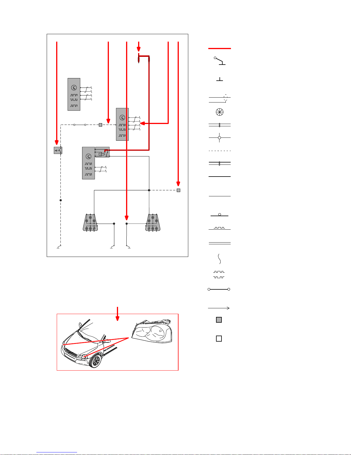
How to use the wiring diagrams 2:2
List of symbols
= System voltage
= Ground connection
via wiring
= Ground connection on
component/chassis
= Screened wire
= Junction point
= Twisted cable
= Electrical connection
= Variant
= CAN communication
= CAN high data signal
(CAN H)
= CAN low data signal
(CAN L)
= MOST communication
= LIN communication
= DIN cable, coaxial cable,
etc.
= Data communication
= CAN communication
= Connection with distribution
box
= Further connection to...
= Connector between
cable harnesses
= Connector connected
to component
CAN
1
1
A
F
BD E C
G
CEM
4/56
CAN
BL
15/20:13
3
5
2
1
4
R
2/80
1
2
3/10
RMI4
3
1
4/58
REM
A:1
SB
31/96
3
54/3LF
15/24:2
Y-GR Y-GR Y-GR
MAN
53/326
SB
MAN
11D/3
2
11
2
11D/4
30+
4/28
TCM
B:14
B:2
B:1
B:13
D:3
D:2
B:17
B:18
10/17
B:1
B:3
31/73
SB
SB
10/4810/55
A:14
A:16
53/604
SB
53/601
SB
31/72
BL
54/51
12
53/615
B:3
B:1
10/18
CAN
CAN
BL
BL
10/1-2
TP3980202 XC90 Premier 2005 7
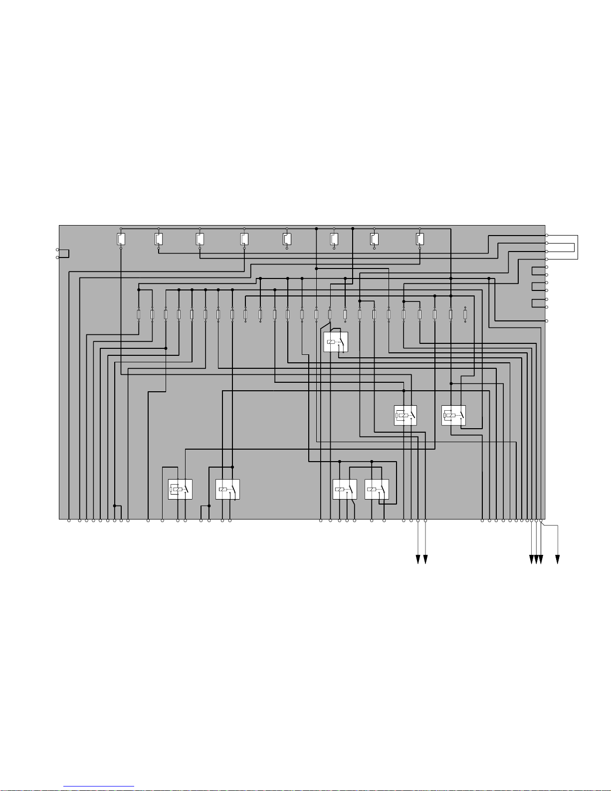
Electrical distribution 1:2
Overview
5
2
1
3
45
2
1
3
45
2
1
3
2
5
3
1
E
R
11A 11A 11A
3
2
1
21212121212121212121212121212121212121212112122
1
17/17
C6:2
C3:2
A1:1
C5:14
C4:11
C4:6
A1:5
C6:1
C4:8
C4:5
C6:9
C6:8
C5:15
C2:2
FST1
2/91
FST3
2/90
C3:4
A1:10
A1:11
C4:9
C4:10
C4:2
C3:3
C3:1
A1:13
2/32
3
2/14
FMA2
5
2
1
FMA3
2
11A
7
22
11A
6
11A
8
11B/14
11B/15
11B/16
11B/17
11B/18
11B/19
11B/20
11B/21
11B/22
11B/23
11B/24
A1:6
C5:11
C4:16
A1:8
C4:12
C4:14
A1:3
C5:13
C6:3
A1:14
A1:2
A1:7
FMI1
2/22
FMA4
2/35
C2:1
15/30
C6:7
5
2
11A
4
11A
3
2 222
2
1
11B/1
11B/2
11B/3
11B/4
11B/5
11B/6
11B/7
11B/8
11B/9
11B/10
11B/11
11B/12
11B/13
B
R-W
SB
F
15/31
1
2
FST2
2/182
3
5
C5:12
C6:4
C4:4
C4:3
C6:12
C6:13
C1:1
C1:2
C4:15
C6:10
C6:6
4
5 4
R
R
C4:1
A1:12
A
BL
D
R
C
BL-R
TP3980202 XC90 Premier 2005 8
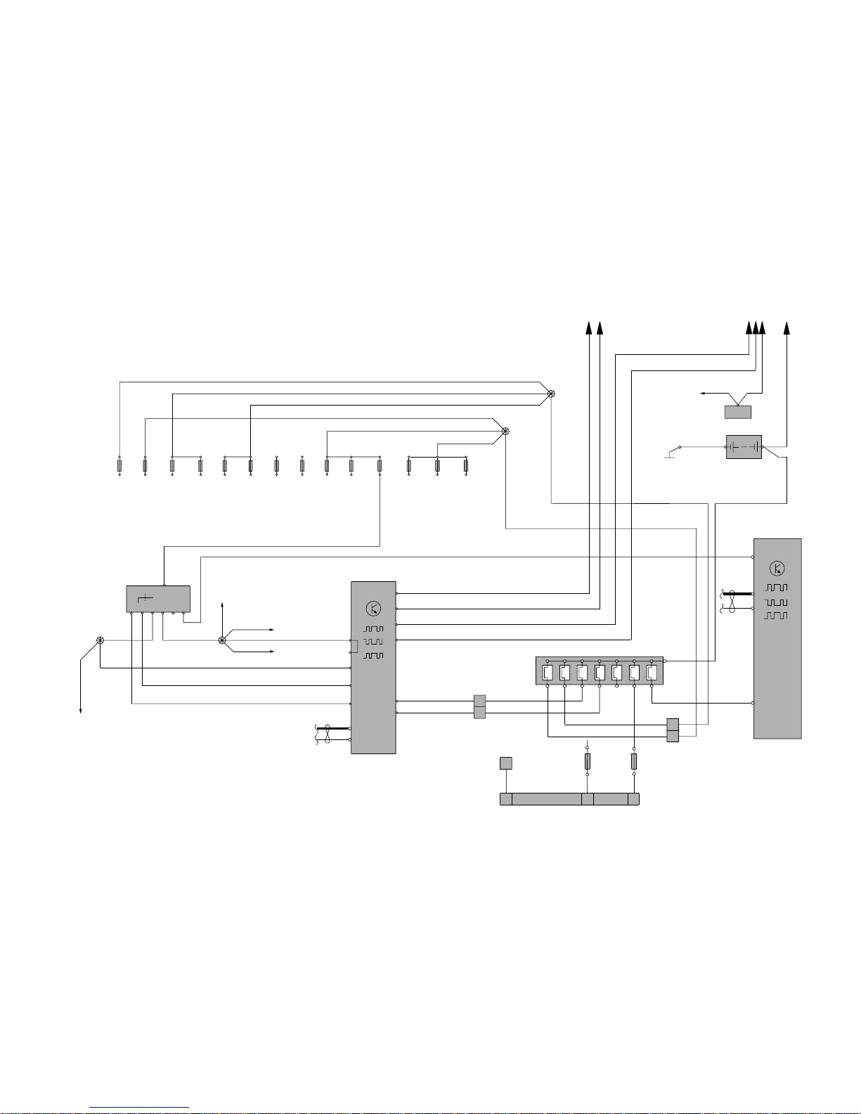
Electrical distribution 2:2
Overview
6/25:1
R
2
R
R
R
R
R
R-W
6/26A:1
BL-R
E
11C/1111C/1
1 1
11C/2
2 2
11C/4
11
11C/3
1
11C/5
222
53/408
11C/8
1
11C/61111C/7
2 22
1
11C/91111C/10
2 22
4
3/1
R-SB
X
30
5
S
37506
15
8
1
15 15I
16/65:1
BL-R
53/443
BL-R
BL-R
11C/1311C/12
1 1
2 2
53/415
4/9B:28/56
3/157:2
1
11E
67
245222322
1
D:16
B:2
B:24
B:3
B:16
D:8
D:15
4/56
CEM
D:60
CAN
1/1
12V
+SB-
31/53
VO
VO
BL-R
2
R
F
SB
C:13
C:14
REM
CAN
LIN
4/58
54/40D
2
VO
C:14
D:50
D:35
LIN
Y
Y-W
R
R
R
53/403
11C/14
1
2
1
E:A
E:B
R
R
R
R
R
R
R
BL
VO
R
54/40C
1
2
K:1
AB DC
BL
BL
R-W
BL-R
R
A:29
4/9B:27/55
1 32
54/303
54/98
3
11F /2
R
11F /1
2
1
2
1
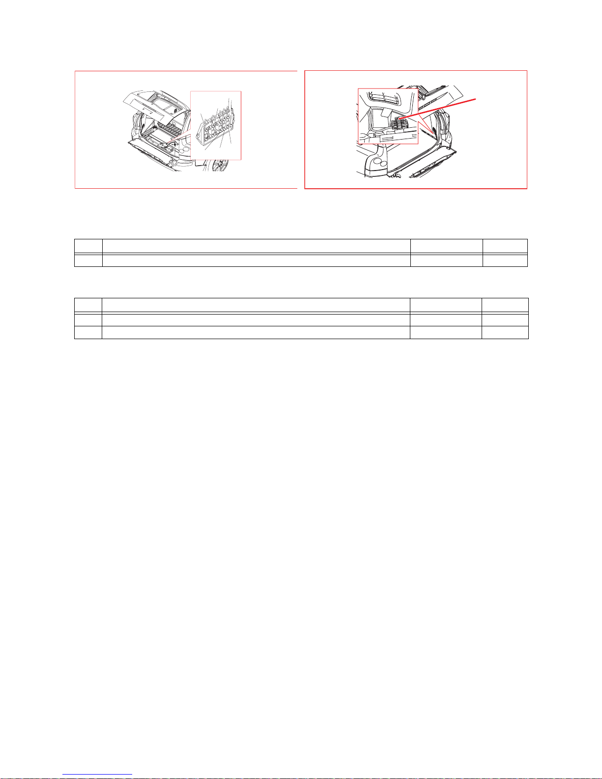
TP3980202 XC90 Premier 2005 9
11E Fuses by the battery
11F Fuses in cargo compartment auxiliary fuse box
No. Fuse function via A
2 16/124 Rear Seat Entertainment module (RSE) - 40
No. Fuse function via A
1 16/124 Rear Seat Entertainment module (RSE), 30 feed - 10
2 16/124 Rear Seat Entertainment module (RSE), X feed - 5
P2S04_11F
11F / 1
11F / 2
P2S04_11E
11E/3
11E/1
11E/2
11E/7
11E/5
Fuses
Cargo compartment 11E & 11F
 Loading...