

Volvo 2001, 2002, 2003, 2003T Workout Manual
FOREWORD
workshop
This
The
instructions
the
heading
Both the
when
ordering
reserve
We
binding
.
UNIT
SI
Units
accordingtothe
Power
TorqueisgiveninNm
is
earlier unithp(horse-power)
earlier unit
earlier unit
PressureisgiveninPa
earlier
earlier
manual
"Special
engine
designation
parts
the
right
giveninkW
kpm
lbf
unit
kp/cm
unit
Ibf/in2(pounds
concerning overhauling
tools"
.
to
SYSTEM
internationalSIsystem
(kilowatt)
(kilopond
ft (poundfoot)earlier unit
2
(kiloponds
contains
.
and
carry
out
(newton
metre)
(Pascal)
metre)
per
repair
its
serial
design
per
square
square
instructions
describe
number
modifications
inch)
the
mustbeclearly
have been
Imp
centimetre)
for
the 2001,
most
and,
for
usedinthis
. gal (Imperial gallon)
2002
suitable
working
statedinall
this
reason,
Speedisgiven
earlier
Volume
earlier
earlier
and
the
book.The
unit
is
givenindm3(cubic
unitl(litre)
unitUSgal
2003
engines
method
correspondence
contentsofthis
rev/min
earlier
in
rev/s
using
Technical
units
(revolutions
(revolutions
(United
.
the
special
concerning
manual cannotberegarded
Publications
are
decimetre)
States
given
per
per
tools
AB
VOLVO
after
second)
minute)
gallon)
listed
the
engine
Department
the
PENTA
SI
under
and
as
units
.

INDEX
Components
DISASSEMBLY
Cylinder
Transmission
Piston,
Flywheel
Crankshaft
Camshaft
OVERHAUL
Disassembling
Valve
Valve
Valves......
Valve
Rocker
Injector
Injectors....
Assembling
Feed-pump.. . ... . . . . . ... . . . . . ... . . . . . ... . . . . . .....
Pistons...... . ....... . ... . . . . . ... . . . . . ..... . . . .....
Crankshaft..
Camshaft.... . ....... . ....... . ....... . ....... . .....
Connecting
Thermostat.. . ....... . ... . . . . . ... . . . . . ... . . . . . ... . .
Sea-water
guide..
head
. ... . ... . .....
. ... . ... . ....... . ..... . . . ....... . ... . . .
piston
. . ... . .
. . . . ... . ... . ....... . ... . . . . . ... . ... . ... . . .
. ... . ... . ... . ....... . .....
..... . ........... . ..... . . . ... . . . . . ... . . .
guides
seats.. . ....... . ....... . ... . . . . . ... . . . . . . . . . . .
. . ....... . ... . ... . ....... . .....
springs
. ....... . ....... . ....... . ... . ... . ... . . .
arm
mechanism...... . ... . . . . . ....... . ..... .
sleeve..
. . ....... . ....... . ..... . . . ....... . ... . ..8
the
...
rods
pump....
. . ....... . ... . . . . . ... . . . . . ... . .
.
. . ....... . ....... . ... . . .
rods..
. . ... . ... . ... . . . . . ....... . ... . . .
... . ....... . ....... . ... . ... . ... . . .
...
. . .
...
.
.
.
the
cylinder
. . ... . ....... . ..... . . . ....... . .....
cylinder
.
...
.
. . . . . . . . . . . ....... . ... . ... . . ... . . .
head.... . . . ..... . . . ... . . .
... .
head
. . ..... . . . ... . . . . . ... . ..9
.
.
. . . . . . ... . . . . . ... . ... . .....
. .
. . ... . . . . . ... . . . . . ..... . . . .....
. . ... . . .
.
. .
. .
.12
.
2
3
4
5
5
5
5
7
7
7
7
8
8
8
.
10
11
11
11
13
13
ASSEMBLY
Crankshaft
Pistons...... . ..... . . . ... . . . . . ....... . ... . ... . ... . .
Flywheel
Transmission
Adjusting the
Checking
2003
Fresh
Electrical
Fault tracing
Special
Technical
... . ... . ... . ... . ... . ... . . . . . ....... . ... . .
. . . . . . ... . ... . ... . ... . ..:........ . ... . ... . .
. ... . ... . ... . ... . ........... . ... . ... . .
valve
clearance
the
injection
Turbo..
water
. . ... . . . . . . . . . . . . . . . .
cooling
system
scheme
tools.. . . . . . . . . . . . ... . . . . . . . . ... . . . . . . . . . . . .
Data.. . . . . . . . ..... . . . . . . . . . . . . . . . . . . . . . . .
. . . . . . . . . . . . . . . . . ... . . . . . . . . . . . .
. . . . . . . . . . . . . . . . . . . . . . . . . . . . . . . . . . .
. . . . . . . . . . . . . . . . ... . . . . . . . . . . . .
. . . . ... . . . ... . . ....... .
angle
. . . . . ... . . . ... . . ... . ... .
. . . . . . . . . ..... . . .
14
14
15
15
17
17
21
25
26
28
29
30
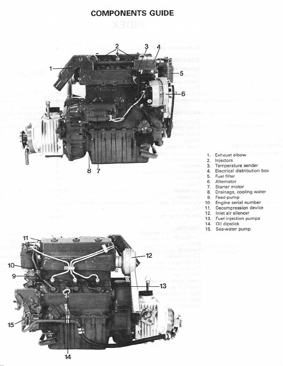
COMPONENTS
8
GUIDE
1
.Exhaust
2.Injectors
3.Temperature
4
.Electrical
5
.Fuel
6.Alternator
7
8
9.Feed-pump
10
11
12
13
14.Oil
15
filter
.Starter
.Drainage,
Engine
.
.Decompression
air
.Inlet
injection
.Fuel
dipstick
.Sea-water
elbow
sender
distribution
motor
cooling
serial
number
silencer
pumps
pump
box
water
device
Halpert@Optonline.net
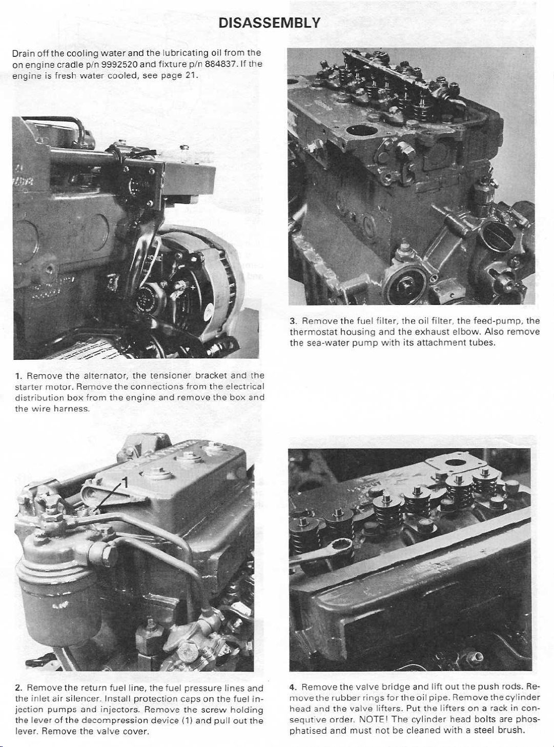
Drain
off
the
on
engine
engineisfresh
cradle
cooling
p/n
water
water
9992520
cooled,
and
the
and
see
lubricating
fixture
p/n
page21.
DISASSEMBLY
oil
from
the
.Ifthe
884837
1.Remove
starter
motor.Remove
distribution
wire
the
harness
the
alternator,
box
from
.
the
the
the
tensioner
connections
engine
and
from
remove
bracket
the
the
and
the
electrical
box
and
3.Remove
thermostat
the
sea-water
the
fuel
housing
pump
filter,
and
with
the
the
its
oil
filter,
exhaust
attachment
the
feed-pump,
elbow.Also
tubes
the
remove
.
2
.
Remove
the
inlet
the leverofthe
lever.Remove
the
air
silencer.Install
pumps
return
fuel
and
injectors
decompression
the
valvecover
line,
the
protection
.
Remove
device
.
fuel
pressure
capson
the
screw
and
(1)
the
pull
lines
fuel
holding
out
and
injection
the
4.Remove
the
head
and
the
rubber
the
valve
rings
valve
and
bridge
fortheoil
lifters.Put the
lift
out
the
pipe.Remove
liftersona
push
the
rack
rods
.
cylinder
in
consecutive
Remove
order, NOTE!Thecylinder
head
boltsare
phosphatised
andmustnot becleanedwitha
steel
brush.

5.Remove
ensure
were
removed.Take
on
the
.
the
fuel
injection
installationinthe
careofthe
side of
the
engine
pumps.Mark
same
block
cylinders
shims.Remove
and
fromwhich
lift
out the
the
pumps
the
pump
they
screws
to
lifters
7.Remove
throttle
the spring
gear
(When
facing
using
camshaft.Remove
and
the
control
the
spring
(3).Remove
wheels
outwards).Remove
the
pinbypunching
pullitstraight
withacolour-pen
installing
special
transmission
cover.Usea
(1).Then
the
the
gear
tool
p/n
it
out,
the
screws
outwards
cover:Startbyremoving
suitable
remove
oil
wheels,
the
bracing
884839.Never
this
.
pump
on
the
before
the
can
the
typeofpliers
end-nipple
cover
removing
marked
pinofthe
remove
very
transmission
and
side
well
to
(2)
and
mark
them
must
camshaft
the
bracing
bend
cover
the
remove
the
.
be
the
6.
Remove
using
the
puller
damaged
puller
and
.
the
pulley
9992265.Place
p/n
the
crankshafttoavoid
center
bolt
a
and
pull
protection
the
crankshaft
off
the
pulley
padbetween
being
8.The
are
set
this
will
9.Remove
the
rearof
holding
max
.-volume-screw
Volvo
by
affect
the
the
block
the
control
Penta
the
engineoutput
control
and
rod
(1)
and
the
max
and
must
never
be
.
rod.Startbyremoving
thetwo
.
screwsonthe
.-rev-screw
changed
the
plug
pump
(2)
since
at
plane,
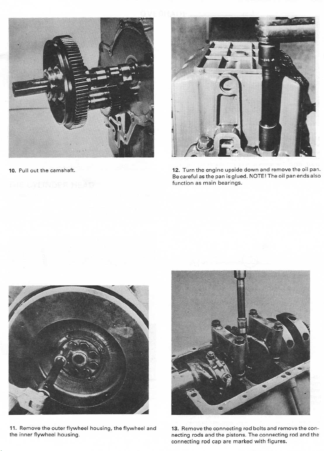
10.Pull
out the
camshaft
oil
pan
.
12.Turn
Be
functionasmain
the
engine
carefulasthe
upside
panisglued
bearings
.
down
.
NOTE!
and
remove
The
oil
pan
the
ends
.
also
11
.
Remove
the inner
the
flywheel
outer
flywheelhousing,
housing
the
flywheel
.
and
13.Remove
connecting
rods
the
and
rod
connecting
the
pistons
cap
are
marked
rod
.
bolts
The
with
and
remove
connecting
figures
the
rod
and
the
connecting
.
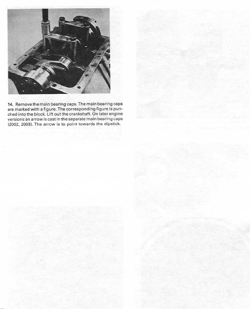
14.Remove
are
marked
versions
(2002,
the
with
into
the
block.Lift
arrowiscastinthe
an
2003).Thearrowisto
main
bearing
a figure.The
out
caps.The
corresponding
crankshaft.On
the
separate
point
main
main
towards
bearing
figure
later
bearing
the
dipstick
caps
is
engine
punched
caps
.

3.Use
the
884559
down
new
mandrel
valve
install
to
to
the
.
p/n
guides
them.Press
cylinder
5218topress
externally
down
head.Ream
out the
and
the
mandrel
the
valve
use
valve
guides.Oil
mandrel
all
the
guides
p/n
way
if
necessary
THECYLINDER
1 .
Remove
bow.Remove
Place
stand
the
"collets"
the valves.Removethe
the
valves
.
HEAD
valve
springs
sequence
and
in
the
proper
valve
using
a
stem
inavalve
valve
seals
.
Valve
guides
2.Check
into
the
necessary,
Wear
limits
Inlet
valve,
Exhaust
the valve
guide.Measure
replace the
valve,
:
max
guide
play
max
wearbyinserting
the play
valve
guides
. ...
. . . . . . ... . .0.15
play
. . . . . . . . . . . .0.15
using
.
anew
a
dial
mm(0.0059
mm(0.0059
valve
stem
indicator.If
in)
in)
Valve
seats
and
valves
4.Millorream
(for
2003T,
(B)
shouldbe1±0.1
in
a valve
the
disc
thickness
for
naturally
bent
stems,orif
in)
must
rockersifnecessary.Lapinthe
paste
and
the
valve
seats.The
30°
for
the
inlet
valve).The
mm(0.039±0
grinding
engines,
alsobescrapped.Grind
check
machine.The
after
aspirated
the
the
the
grindingisless
engines
valves
measurement
contact
area
angle
sealing
.0039
in).Grind
angle
(D),
than
or 0.8mm
must
bescrapped.Valves
(A)
exceeds2.5mm(0
valve
the
valves
using
with
marking
shouldbe45°
(C)
surface's
the
valves
Tech.data.If
see
1.0mm(0.039
in)
for
(0.031
tip
towards
valve
grinding
dye
.
width
in)
with
turbocharged
.098
the
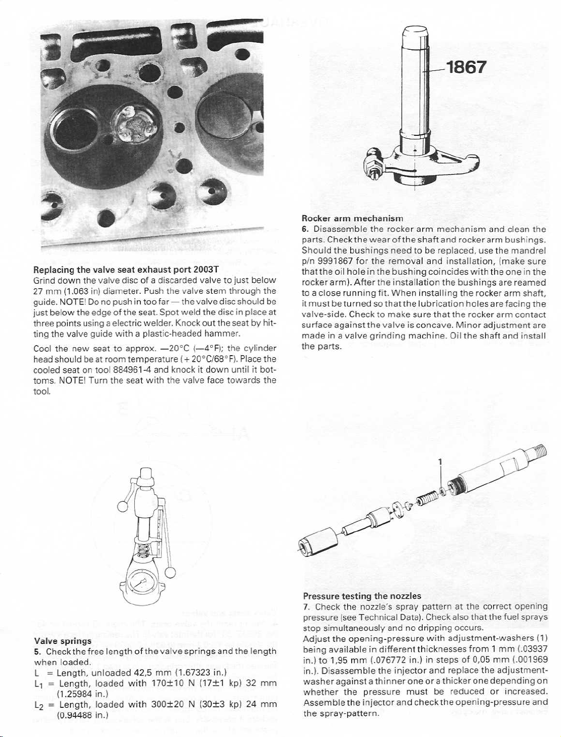
Replacing
Grind
27
mm(1.063
guide.NOTE!Do
just
three points usingaelectric
Cool
head
cooled
tool
down
below
the
the
should
.
valve
new
seat on
NOTE!
the
the
the
beat
Turn
valve
seat
valve
discofa
in)
diameter
not
push
edge
of the
withaplastic-headed
guide
to
tool
approx.-20°C
room
temperature
884961-4
the seat
seat
exhaust
.
in too
seat.Spot
port
discarded
Push
the
valve
far-
the
weld
welder.Knockout
(+
and
knockitdown
with
the
valve
2003T
valve
to just
below
stem
through
valve
disc
should
the
discinplace
the seat
hammer
(-4°F);the
20°0168°F).Place
face
.
cylinder
until
towards
by
it
the
be
at
hitting
the
bottoms.
the
Rocker
6
parts.Check
Should
p/n
that
rocker
toaclose
it
valve-side
surface
made
the
arm
.
Disassemble
the
9991867
the
arm)
must
beturnedsothat
inavalve
parts
mechanism
the
bushings
for the
oil
holeinthe
.
After
running
.
Checktomake
againstthe
.
the
rocker
armmechanism
wearofthe
the
fit
valveisconcave.Minor
grinding
shaft
needtobe
removal
bushing
installation
. When
installing
the
lubrication
sure
machine.Oil
replaced,
and
coincides
that the
and
rockerarm
usethe
installation,
with
the
bushings
the rockerarm shaft,
holes
rocker
adjustments
the
shaft
and
(make
the
are
are
arm
and
clean
the
bushings
mandrel
sure
oneinthe
reamed
facing
the
contact
install
.
are
Valve
springs
5.Checkthe
when
loaded
L =
Length,
L
1 =
Length,
(1
.25984
L2=
Length,
(0
.94488in.)
free
length
.
unloaded
loaded
in
.)
loaded
of
42,5
with
with
the
valve
mm
170±10N
300±20
springs
(1
.67323in.)
(17±1
N
(30±3
and
kp)
kp)
the
length
32
24
Pressure
7.Check
pressure
stop
Adjust
being
in.)to 1,95
in.).
mm
whether
mm
Assemble
the
testing
the
nozzle's
(see
Technical
simultaneously
the
opening-pressure
available
mm(.076772in.)insteps
Disassemble
the
pressure
the
injector
spray-pattern
the
nozzles
spray
Data)
andnodripping
in
different
the
injector
and
.
patternatthe
Check
.
with
thicknesses
and
must
be
check
correct
also that the
occurs
.
adjustment-washers
from1mm
of
0,05
mm(.001969
replace
reduced
the
the
or
opening-pressure
opening
fuel
sprays
(1)
U3937
adjustment-washer
increased
againstathinneroneorathickeronedependingon
.
and
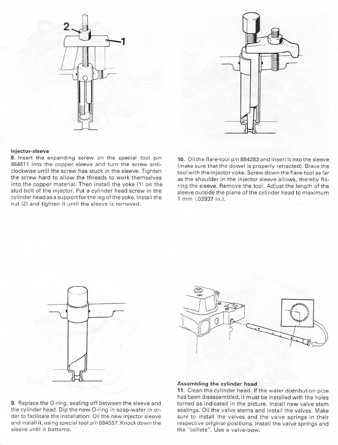
Injector-sleeve
8.Insert
884811
the
into
stud
cylinder
nut
screw
the
bolt of
(2)
and
into
the
hardtoallow
copper
the
headasa
tightenituntil
expanding
the
copper
material.Then
injector.Putacylinder
supportforthe
screw
sleeve
the
the
threads
on
the
special
and
turn
the
to
work
install
the
yoke
head
legofthe
sleeveisremoved
yoke.Install
tool
p/n
screw
anti-clockwise
themselves
(1)
on
the
screwinthe
the
.
until
the
screw
has
stuckinthe
sleeve. Tighten
10.Oil
(make
with
tool
as
the
sleeve
1
mm
theflare-tool
sure
that
the
shoulder
the
sleeve.Remove
outside
(
.03937in.)
the
injector
in
the
.
p/n
884283 and
dowelisproperly
yoke.Screw
the
injector
planeofthe
the
tool.Adjust
sleeve
cylinder
insertitintothe
retracted).Brace
down
the
flare-toolasfar
allows,
the
headtomaximum
thereby
length
sleeve
the
flaring
of the
9.Replace
the
cylinder
to
facilitate
and
install
sleeve
untilitbottoms
the
O-ring,
head.Dip the
the
installation.Oil
it,
using
special
sealing
new
tool
.
off
between
O-ring
the
p/n
884557.Knock
the
in
soap-water
new
sleeve
injector
down
and
in
order
sleeve
the
Assembling
11.Clean
has
been
turnedasindicatedinthe
sealings.Oil
suretoinstall
respective
the
"collets".Useavalve-bow
the
cylinder
the
cylinder
disassembled,
the
valve
the
valves
original
positions.Install
head.If
stems
head
the
water
it
must
be
installed
picture.Install
and
install
and
the
.
distribution
with
new
the valves.Make
valve
springs
the
valve
the
valve
in
springs
pipe
holes
stem
their
and
 Loading...