

Volvo 120 Operating & Service Manual
2-DOOR
CARS
(120 T)
DESCRIPTION
OPERATING INSTRUCTIONS
SERVICING

BEFORE YOU START DRIVING YOUR NEW VOLVO PLEASE
READ THROUGH THIS INSTRUCTION BOOK CAREFULLY.
I
T CONTAINS ALL THE INFORMATION YOU NEED TO
BE ABLE TO DRIVE AND SERVICE YOUR VEHICLE IN THE
BEST POSSIBLE WAY. BY FOLLOWING THE INSTRUCTIONS
GIVEN IN THIS BOOK, YOU WILL FIND THAT YOUR
VOLVO WILL COME UP TO ALL THE EXPECTATIONS
CONCERNING ECONOMICAL OPERATION AND EXCELLENT
PERFORMANCE THAT YOU HAVE EVERY RIGHT TO
EXPECT OF A TOP-QUALITY VEHICLE. DO NOT WAIT
UNTIL SOMETHING GOES WRONG BEFORE YOU START
READING THIS BOOK. READ IT NOW. THE SHORT TIME
THIS TAKES WILL MORE THAN REPAY YOU IN THE
LONG RUN. THIS INSTRUCTION BOOK IS NOT INTENDED
TO BE A COMPREHENSIVE TECHNICAL MANUAL AND
DOES NOT CLAIM TO MAKE THE READER INTO A PERFECT
CAR MECHANIC. IT WILL, HOWEVER, SHOW YOU HOW
TO LOOK AFTER YOUR VEHICLE SO THAT TROUBLE
I
N FUTURE CAN BE AVOIDED. FOR A MORE DETAILED
MECHANICAL DESCRIPTION AND REPAIR PROCEDURES, YOU
ARE REFERRED TO THE SPECIAL SERVICE MANUAL
FOR THE VEHICLE.
CONTENTS
VOLVO SERVICE
page
The Volvo Service Organization
4
Warranty and Service Booklet
5
Service Inspections
5
TECHNICAL DESCRIPTION
page
Type designations
6
Engine
8
Electrical system
9
Power transmission
1
0
Brakes
11
Wheels and tyres
11
Body
1
2
I
nstruments and controls
1
6
OPERATING INSTRUCTIONS
page
Running-in
22
Starting the engine
23
Gear-changing
24
Points worth noting
25
S E R V I C I N G
page
General
27
Maintenance scheme
28
Lubrication
30
Engine
34
Electrical system
39
Power transmission
43
Brakes
43
Front end
43
Wheels and tyres
44
Body
46
Servicing before long-distance trip
49
Procedure in cold weather
50
Lubricating chart
60
FAULT TRACING
page 52
SPECIFICATIONS
page53
3

VOLVO SERVICE
4
Volvo Service Organization
I
n order to get the most out of the invested capital represented by a car,
itmust be looked after and serviced regularly. Volvo has gone to a great
deal of trouble in the design and selection of material to ensure that
the car in question only requires a minimum of servicing. All this work
will
be in vain unless we can count on your co-operation - that is to
say, that you make sure that your vehicle gets the regular servicing it
needs. In order to help you, Volvo has built up a world-wide service
organization.
All
Volvo dealers have specially trained personnel and
receive a continuous supply of technical information from the Volvo
Service Organization concerning repairs and adjustment work. They
have also special tools, designed at the Volvo factory.
All
Volvo dealers have a comprehensive stock of spare parts which is
your guarantee for genuine Volvo spares. Our dealers are, therefore, in
the very best position to give your vehicle first-class service concerning
both maintenance operations and repairs. You should also refer to your
dealer if you need information about your Volvo that is not included in
this instruction book .
Not only is there a Volvo workshop within easy reach in your own
country:
Volvo has also a widely distributed service network in other
countries.
VOLVO SERVICE
Warranty and Service Booklet
A warranty and service booklet accompanies each vehicle when it is
delivered. This book contains a coupon entitling you to a free service
i
nspection after 2 500 km (1 500 miles). If possible, let the dealer who
supplied the vehicle carry out this service inspection. If necessary,
however, any of our dealers can do this.
If
our six-month guarantee is to apply, we make one absolute condition
and that is that the above-mentioned free inspection is carried out
at roughly the mileage shown and that the vehicle has been looked after
i
n accordance with the instructions in this book.
Service Inspections
After the free service inspection has been carried out, you should
make an agreement with your dealer concerning continued, regular ser-
vice inspections in accordance with the suggestions made in our Ser-
vice Book. Thorough and regular servicing is of vital importance for the
performance and length of life of the vehicle.
Always use genuine Volvo spares.
5
Type designations
This instruction book deals with cars having the
following type designations (note that some variations are not to be found on certain markets)
6
DESCRIPTION
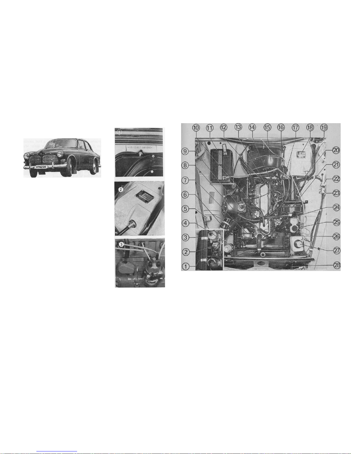
1.
The car type designation and chassis number
are stamped on the cowl under the bonnet.
2.
Stamped on a plate to the left under the bonnet
i
s the type designation together with the code
numbers for colour and upholstery.
3.
The engine type designation, part number and
serial number are given on the left-hand side of
the cylinder block. The last figures of the part
number are stamped on a tab. The serial number
follows this with all the figures stamped on. For
i
dentifying the engine, both the part number and
serial
number should be quoted, for example
496918-3456.
I
n all correspondence concerning your vehicle with
the dealer and when orderi
ng spare parts, the type
designation,
chassis
and
engine number should always be quoted.
Engine compartment (B 20 A)
7
Engine (B 20 B)
1.
Air cleaner (B 20 B)
10.Hoses for positive
19.Fusebox
2.
Floatchamber (B 20 B)
3.
Carburettors (B 20 B)
11.
crankcase ventilation
Battery
20.
Oil filler cap
21.
Brake servo cylinder
4.
Expansion tank with
1
2.
Hoses for heater system
22.
Relay for reversing lights
filler cap for coolant13.
Oil dipstick
23.
Relay for headlight flasher
5.
Voltage regulator
14.
Distributor
24. Fuel pump
6.
Hoses for air preheating
7.
Alternator
8.
Air cleaner (B 20 A)
15.Car heater
1
6.
Starter motor
25.
Brake fluid container
26. Steering box
27.
Windscreen wipers
17.I
gnition coil
9.
Carburettor (B 20 A)
18.
Data plate - type,
28.
Horn
upholstery colour code
Type designation
Engine
Gearbox
1
3-134
B 20 A
M 40
1
3-334
B 20 B
M 40
1
3-344
B 20 B
M 40

Engine
8
DESCRIPTION
The engine is a four-cylinder carburettor unit with overhead valves. The
pistons are made of light-alloy and the upper compression rings on
each piston are chromed. The main bearing and big-end bearing shells
are replaceable. The crankshaft is statically and dynamically balanced.
Engine type B 20 A has an output of 90 h.p. (SAE) and is equipped with
a Zenith-Stromberg horizontal carburettor. (On certain markets SU horizontal carburettor.)
Engine type B 20 B has an output of 118 h.p. (SAE) and is equipped
with twin SU horizontal carburettors. (On certain markets twin ZenithStromberg horizontal carburettors.)
Fuel system
Fuel is fed from the tank to the carburettor by a fuel pump which is
driven by a cam on the engine camshaft. There is a filter in the fuel
pump which traps water and other impurities in the fuel.
Exhaust emission control
The engine is fitted with exhaust emission control, that is, a system as a
result of better mixing and distributing of fuel and air provides a more
complete combustion and thereby cleaner exhaust gases. On the B 20 A
engine, the exhaust emission control is obtained through the carburettor
which is specially designed for this purpose. On the B 20 B engine the
exhaust emission control is provided partly through carburettors specially
designed for this purpose and partly by the engine having a special induction manifold with throttles and preheating chamber. When driving at
l
ow speeds the throttles are closed so that the fuel-air mixture is forced
to pass the preheating chamber.
When higher output is required, the throttles open so that the fuel-air
mixture flows directly to the cylinders.
It
DESCRIPTION
Air preheating
Certain variations of the 120 models are provided with thermostatically
controlled air preheating.
With this arrangement the induced air is maintained at a constant, favourable temperature. Air preheating counteracts ice formation in the carburettor and also contributes to a shorter warming up period after starti
ng from cold.
Lubricating system
The engine lubrication is taken care of by a gear pump which sucks up
oil from the sump on the bottom of the engine and forces it through the
oil filter out to the lubricating points in the engine. A relief valve is built
i
nto the oil filter which prevents the oil pressure from reaching exces-
sively high values.
Cooling system
The engine is water-cooled and the cooling system is of the pressure
type.
Water is circulated by means of a pump fitted on the fan shaft.
A wax-type thermostat with an opening temperature of about 82
°
C
(180°F)
prevents the cooling water from passing through the radiator
before the engine has reached its normal working temperature. On
certain
markets a fan with a slip-type coupling is fitted.
Electrical system
The electrical system is of the 12-volt type and is fitted with a voltage-
regulated alternator. The starter motor is operated from the instrument
panel by the ignition key, which also switches on the rest of the electrical
system. The cables to the headlights, parking lights and internal lighting,
however, are not taken over the ignition switch but can be switched on
and off without the ignition key being in position.
9

DESCRIPTION
Lighting
The lighting on the car consists of two headlights (mainbeam and
dipped) together with two combined flasher and parking lights. The rear
l i
ghting consists of two tail lights including flashers, combined lamps
for the tail lights and brake warning lights as well as the reversing light.
I
nternal lighting consists of a roof light above the rearview mirror and
a light for the parcel shelf.
See pages 40-42 concerning replacement of bulbs.
Fuses
The electrical system is protected by means of fuses fitted in a fusebox
to the left on the bulkhead under the bonnet. When replacing a fuse,
be sure that you use one with the right rating. If any fuse should blow
repeatedly
,
do not fit a more powerful fuse. Instead, have a workshop
check the electrical system.
Power transmission
The clutch is of the single dry plate type with diaphragm spring. The
diaphragm spring functions partly as a lever when declutching and partly
as a pressure spring when engaging. Clutch pedal pressure is transmitted
mechanically to the release fork.
Clutch
Gearbox
The gearbox is used to regulate the speed ratio between the engine and
the rear axle so that the engine always operates in its most favourable
speed range. The gearboxes are fully synchronized. The M 40 gearbox
i
s four-speed.
10
DESCRIPTION
Propeller shaft
The propeller shaft, which is the connecting link between the gearbox
and the rear axle, is divided into two sections. The front section is
journalled at its rear end in a bearing housing consisting of a rubberized
ring.
Rear axle
The engine driving power is transmitted via the propeller shaft to the
rear wheels through the rear axle. The rear axle is of the hypoid type,
that is, the drive pinion is below the centreline of the drive shafts.
On certain markets, the rear axle is fitted with a differential brake as
extra equipment. The function of the differential brake is to transfer
automatically the pulling power to the wheel with the best grip on the
road surface when one of the wheels begins to skid. Except for the
differential, the rear axle is similar to a conventional rear axle.
Brakes
The brake system is of the two-circuit type with disc brakes front and
drum brakes rear. The system is provided with a tandem-type master
cylinder and a directly-operating booster cylinder.
The principle of the two-circuit system is that both front wheels are
connected to a rear wheel. Should there be a failure in one of the circuits
there is always braking power on both front wheels and the other rear
wheel. The pressure lines to the rear wheels are fitted with relief valves
which prevent involuntary locking of the rear wheels.
This system has a warning light located on the instrument panel. The
warning light shows if there is a failure in one of the circuits when
braking. It also serves as a warning light for the handbrake.
Wheels and tyres
The car has pressed steel wheels with lugs for the attachment of the
hub caps. All wheels are carefully balanced and the tyres are of the
tubeless type. Tyre size: 165 S 15, 165 SR 15, or 6.85-15.
11
DESCRIPTION
Body
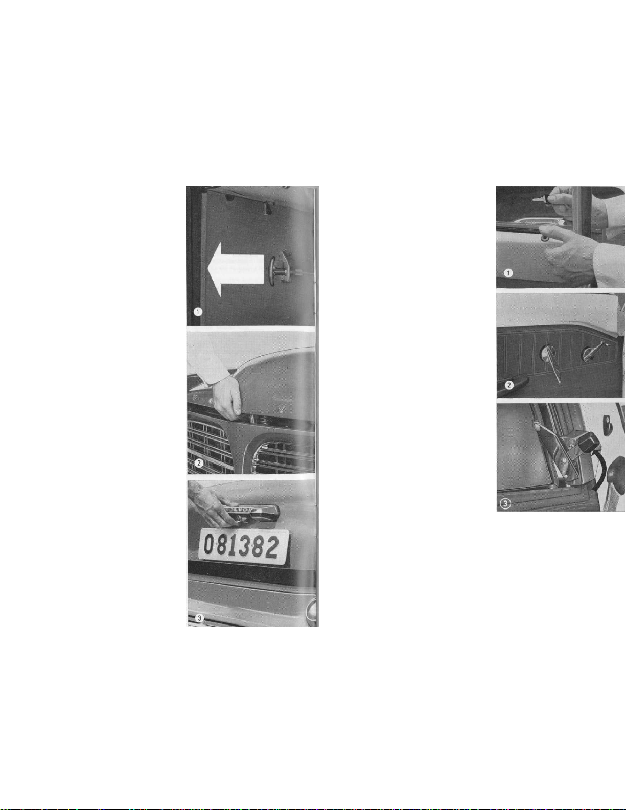
Bonnet
•
The bonnet is fitted with a locking catch
which is operated from the driving seat
by means of a handle located to the
l
eft under the dashboard.
Pulling out the handle releases the bon-
net.
•
When the bonnet locking catch has been
released, the bonnet is still retained by
a safety catch. Press up this catch as
shown in the picture opposite and the
bonnet can be lifted up. Closing the
bonnet locks it so that it can only be
opened by pulling out the release handle.
Always make sure that the bonnet locks
properly when closed.
Boot
•
The boot is locked with the same key
as that used for the doors. The lid is
opened by pressing the handle upwards
as shown in the picture opposite. The
li
d is balanced and will thus remain in
the position opened. In the boot to the
l
eft there is space sufficient for the
spare wheel and a tool kit. Always make
sure that the spare wheel is fastened
securely and that the tool kit is firmly
stowed, otherwise irritating rattles can
occur.
1
2
Doors and locks
•
Both the doors are fitted with a lock
and keyhole.
Both doors can be locked from inside
the
car
by pressing down the lock
button on the window ledge. The lock
button lifts automatically when the door
isopened from the inside. The doors
can be locked from the outside by pressi
ng the lock button on the window ledge
and shutting the door. Do not leave the
keys in the car.
•
The doors are opened from the inside by
pulling the door handle to the rear. The
ventilation
windows for the doors are
opened by unscrewing the lock stud,
pressing it in and then turning the handle
upwards. Screwing in the stud locks the
handle.
•
The rear side windows can be partly
opened by turning up the catch as
shown in the picture.
To prevent the locks from freezing up
i
n cold weather, apply a suitable antifreeze agent. If the locks are already
frozen, do not exert undue force on the
key otherwise you might break it. Instead, heat it with a match or similar and
place it quickly in the keyhole.
Should you lose the car keys, contact
your nearest Volvo dealer for new keys
and quote the code number of the keys
which have been lost.
1
3
DESCRIPTION
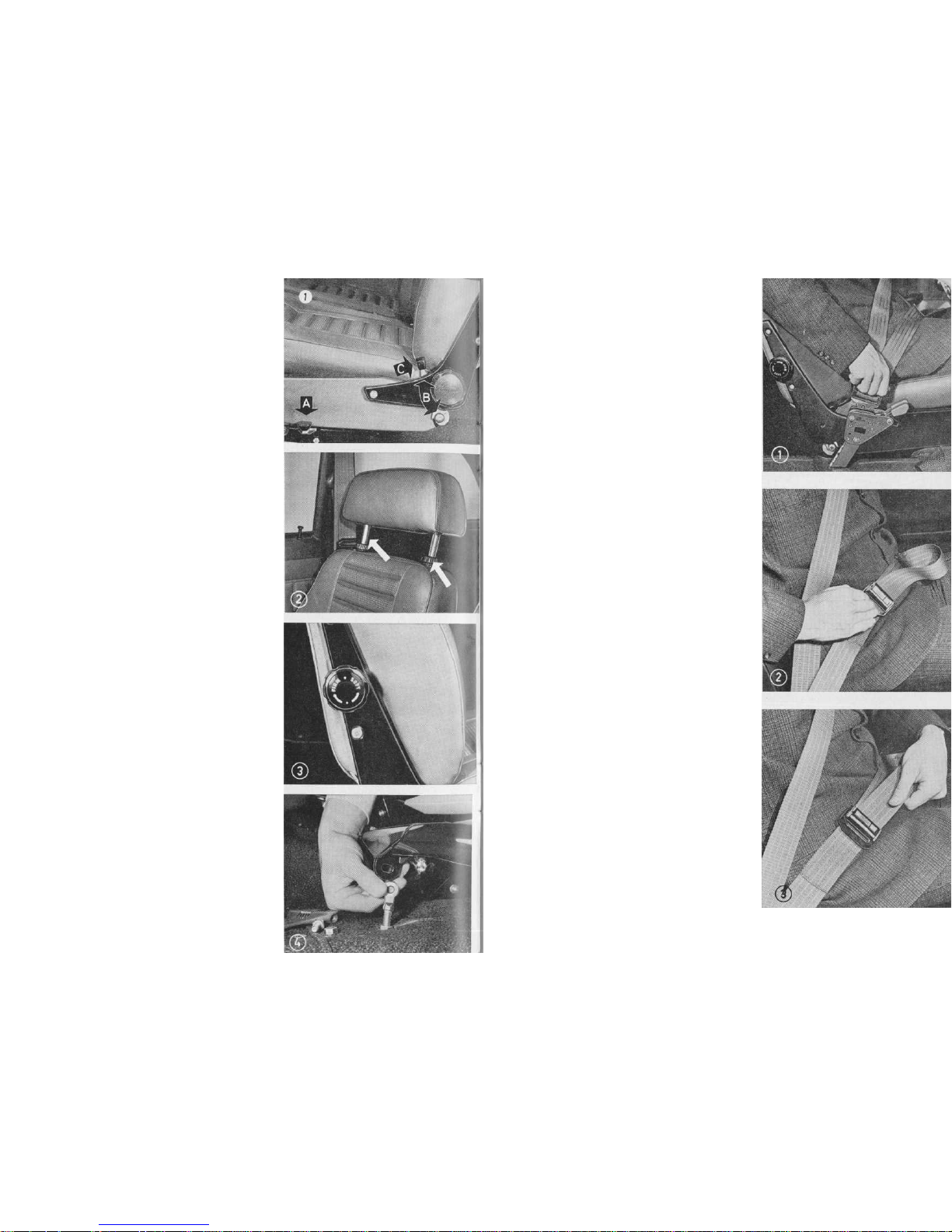
Front seats
•
The front seats can be moved backwards or forwards after the knob (A) is
pressed down. If necessary, the seats
can be moved further to the rear than
permitted by the slide rail by using the
extra holes in the seat frames.
The backrest inclination of the front
seats is smoothly adjusted by means of
a knob (B) on the outside of the seat.
A catch automatically locks the backrest
and thus prevents it from falling forwards. To fold the backrest backwards,
release the catch (C).
•
The front seats are provided with head-
rests.
Before driving, always make sure
that the headrest is at the proper height.
To adjust, slacken the plastic nuts on
the headrest holders. The car is delivered
with the headrests adjusted to a standard height. After adjusting lock them
by turning the plastic nuts clockwise.
•
The front seats are also provided with
an adjustable lumbar support. To tension
the lumbar support, and thus exert more
pressure against the small of the back,
turn the knob clockwise. Turning it anticlockwise slackens the tension on the
support
and
reduces
the
pressure
against the small of the back.
•
The inclination
angle of the entire seat
can be adjusted with the eyelet screw
at the front under the seat. Remove the
screw which goes through the eyelet
and tip the seat backwards as shown in
the picture. Then slacken the locknut on
the floor and screw the eyelet screw upwards or downwards to the desired
height.
Then secure the eyelet screw
with the locknut.
The whole seat can be raised or lowered,
which is done as follows: Remove the
seat cushion, also the screw and nut on
the seat frame attachment on the floor.
Then place the screw in one of the other
holes in the attaching bracket.
1
4
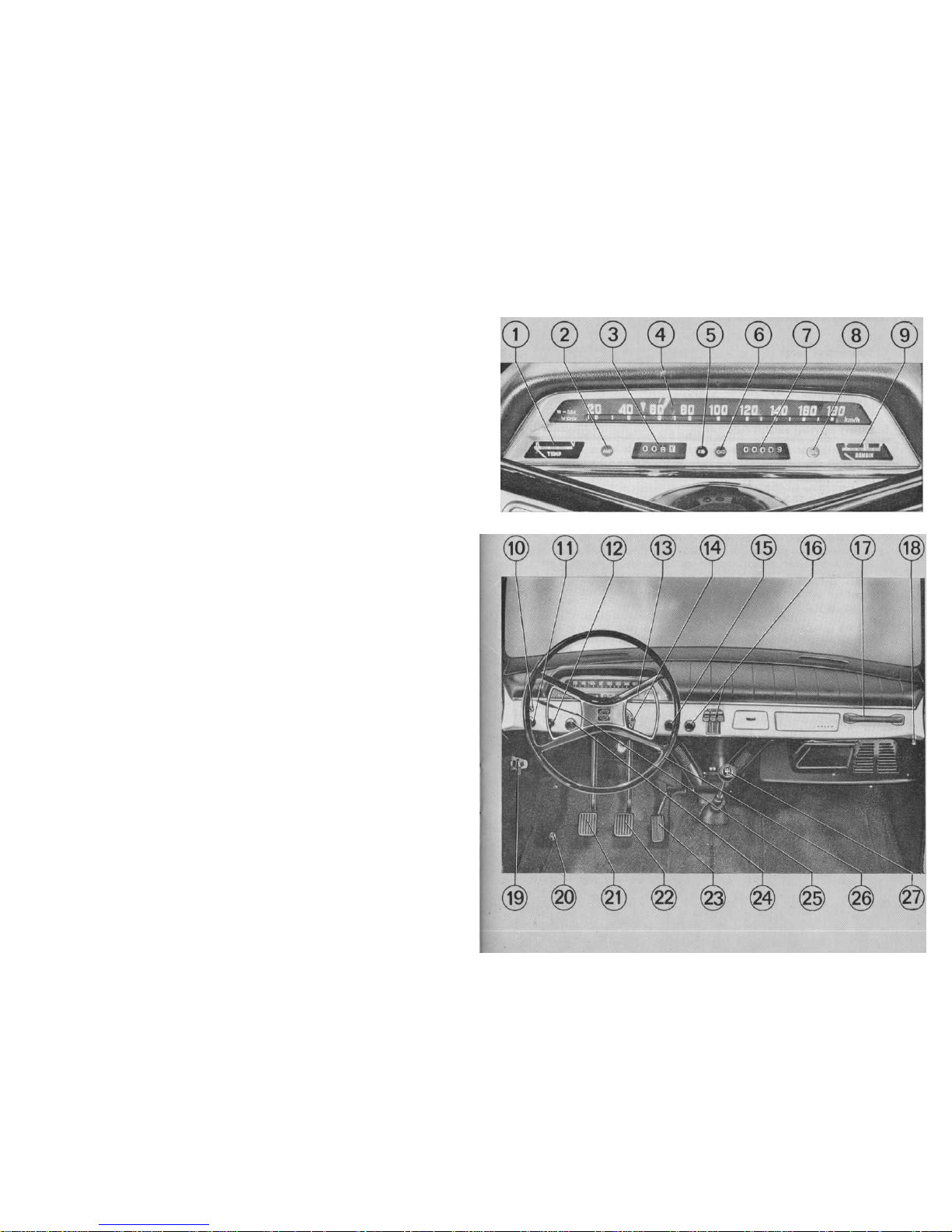
Safety belts
•
Always use the safety belt when driving.
Place one strap across the lap and the
other over the shoulder and chest and
fasten the belt by inserting the buckle
tongue into the locking device between
the front seats. A loud clicking noise
i
ndicates that the belt is locked.
Make sure that the parts of the belt in
contact with the body are not twisted.
Always ensure that the belt is so adjusted that it fits well against the body.
•
Ifthe belt requires lengthening, make
sure that the upper part of the lap strap
i
s slack and take hold of the adjusting
grip
with one hand and with the other
hand pull out to the desired length. Tidy
up any slackness by pulling in the upper
part.
•
I
f the belt is to be shortened, pull in the
upper part of the lap strap. The belt is
released from the locking device by
moving to the rear the lever concerned
on the locking device. Do not let the
belt lie on the floor otherwise it will
become dirty and probably be a hindrance
when getting in and out of the
car. Now and again check that the bolts
anchoring the belt are properly tightened and that the belt is in good condition.
Use water mixed with a synthetic
washing agent for cleaning the belt.
As the safety belts lose much of their
strength
when
exposedtoviolent
stretching, they should be replaced after
a collision,even though they may
appear to be undamaged. Never modify
or repair the belt on your own but have
this done by a Volvo workshop.
Rear seat
On certain markets, two rear safety belts
are fitted as standard. These are of the
2-point lap type.
The belts are fastened by pushing the
buckle tongue on one part of the belt
i
nto the lock of the other.
To release simply lift up the spring-
l
oaded cap on the lock.
I
n principle the belts are adjusted in the
same way as for the front seat belts.
DESCRIPTION
1
6
1.
Temperature gauge
2.
Warning light, battery charging
3.
Trip meter
4.
Speedometer
5.
Mainbeam control light
6.
Turn indicator control light
7.
Mileometer
8.
Oil pressure warning light
9.
Fuel gauge
10.Warning lamp, handbrake,
brake system
11.
Windscreen wiper and washer
switch
12.Choke control
13.Horn ring
1
4. Ignition switch and steering
wheel lock
I
nstruments and controls
Before you start the car, sit behind the wheel and carefully check
through all the instruments and controls. The location of these is shown
i
n the illustration opposite. The instruments and controls are described
inmore detail on the following pages with reference to the numbers in
the illustration. Note that variations may occur on different markets.
I
mmediately after starting, and now and then while driving, glance at the
i
nstruments to make sure they are showing normal readings according
to the values given in the following text.
15.Cigarette lighter
1
6.
Fan switch, heater/ventilation
controls
17.Grab handle
18.Switch for glove locker light
19.Bonnet release handle
20. Foot dipper switch
21.
Clutch pedal
22.
Brake pedal
23.
Accelerator pedal
24. Lighting switch
25. Turn indicator, switch
headlight flasher
26.
Steering wheel
27.
Gear lever
DESCRIPTION
1
2
This light goes on when the battery discharges. If it goes on during
driving, this means either that there is some fault in the electrical system
or that the 'fan belt is not sufficiently tensioned and is thus slipping on
the pulley, causing poor charging.
3
Trip meter
The trip meter, which is graduated in tenths of a mile, can be used to
measure even short distances. The meter can be reset to zero by means
of a reset knob placed under the instrument panel to the left of the
steering column. The knob is turned first to the right and then to the left.
4
Speedometer
The speedometer has a horizontal red ribbon indicator, the ribbon point
showing the speed at which you are travelling. Since the length of the
red ribbon is proportional to the speed, this is in itself a safety factor
- the more red shown, the more dangerous your speed.
7
Mileometer
The mileometer shows the total distance covered in miles. After 99999
miles it returns to zero and starts going round again.
8
Oil pressure warning light
This light goes on when the engine oil pressure is too low. When the
i
gnition is switched on, the light should go on and then go out again
when the engine has been started. Never start driving until the light goes
out.
Should the light remain on during driving, the engine should be
stopped and the cause for this determined. In most cases it means that
the oil level is too low. After hard driving it may happen that the warning
li
ght comes on when the engine is at idling speed. This is normal provid-
i
ng it goes out again when the engine speed is increased.
18
The windscreen wiper and washer switch has four positions. When
pressed fully in, the switch is switched off. When the switch is pulled
out to the first position, the windscreen wipers operate at normal speed.
When it is pulled out to the second position, the wipers operate more
quickly. Pulling the switch out fully also operates the windscreen washers.
The liquid container for the windscreen washers is placed under the
bonnet and holds about 1.5 litres (2.6 Imp. pints = 3.2 US pints). Never
allow the wiper blades to operate on a dry and dusty surface since this
can easily scratch the glass and 'blades.
12
Choke control
The choke control is used when the engine is started from cold. When
pulled out about 10-15 mm ('/
2
") the control operates the throttle flap
and increases idling speed. Pulling the control out further, enriches the
fuel-air mixture, and this steps up the idling speed.
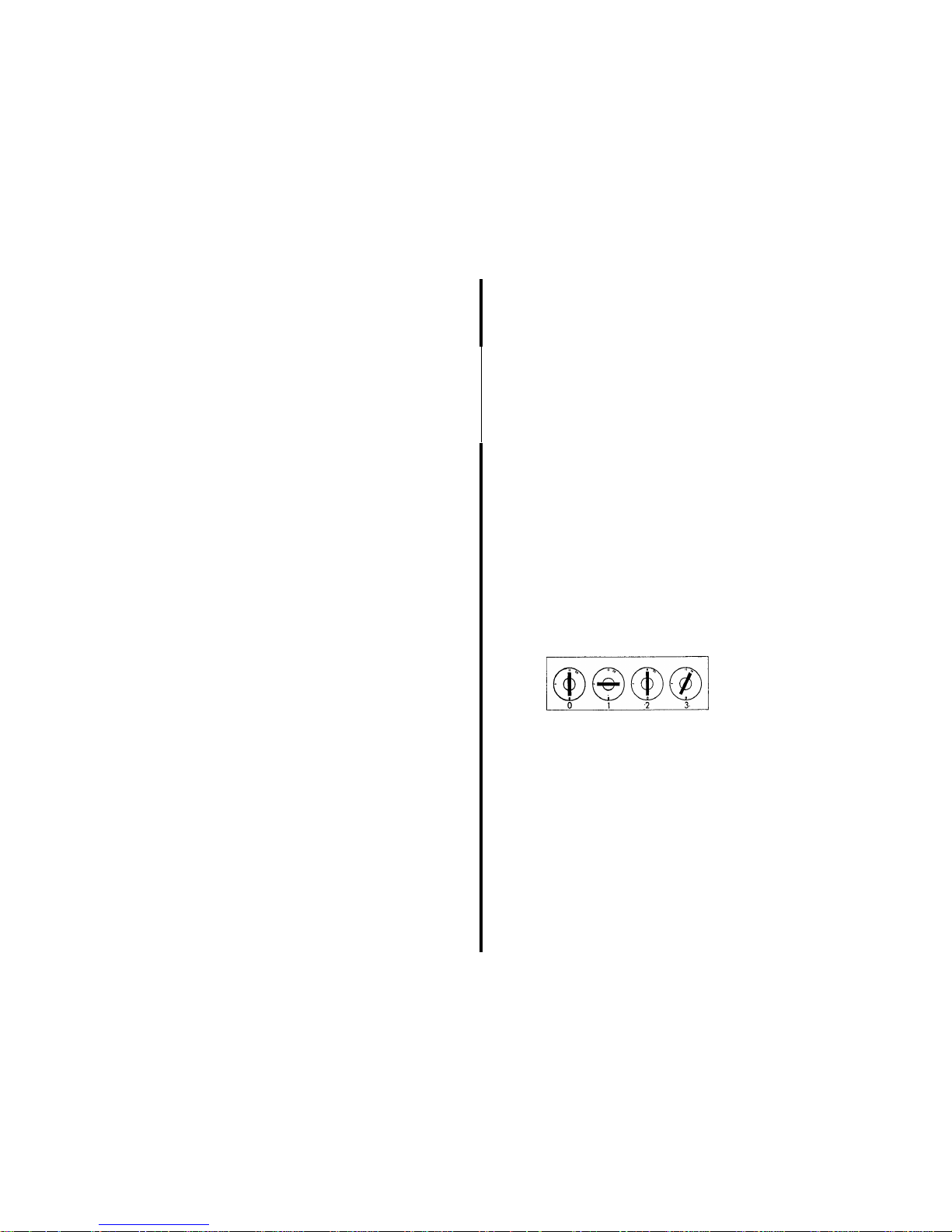
14
Combined ignition switch and steering wheel lock
The switch has four positions:
(0) Locking position, (1) Garage
position, (2) Driving position and
(3)
Starting position.
The key can be taken out of the
l
ock in the Locking position.
Removing the key when in the
Locking
position automatically
l
ocks the steering wheel. With
the key in the Garage position,
the entire electrical system is
DESCRIPTI
ON
connected up except for the
engine ignition system.
During driving, the key should
be in the Driving position.
To start the engine, turn the key
to the Starting position and this
automatically engages the starter
motor. As soon as the en-
gine starts,
release the key
which automatically returns to
the Driving position.
I
f the car is parked in such a
way as to make it difficult to un-
l
ock the steering wheel, unlock-
i
ng can be made easier by
slightly
turning
the
steering
wheel
one way and then the
other.
15
Cigarette lighter
To use the cigarette lighter, push it in. As soon as it attains sufficient
heat, it will automatically spring out.
19
Temperature
gauge
10
Handbrake warning light
Battery
The temperature gauge shows the temperature of the coolant and thus
1 t
This lights red when the handbrake is applied and the ignition is on.
The light also functions as a warning light should a failure arise in one
of the brake service circuits. If the light goes on when driving, the car
should be taken without delay to a workshop for a check on the brake
system. Observe due care when driving on such occasions.
Windscreen wiper and washer switch
i
ndicates the working temperature of the engine.
gauge should remain within the green sectors.
charging warning light
The pointer on this
 Loading...