

Page 1

Labornetzgerät PS-1305-230
쮕
BEDIENUNGSANLEITUNG
Seite 4 - 14
Laboratory Power Unit PS-1305-230
OPERATING INSTRUCTIONS Page 15 - 25
Alimentation de laboratoire PS-1305-230
NOTICE D’EMPLOI Page 26 - 36
Laboratoriumvoeding PS-1305-230
GEBRUIKSAANWIJZING Pagina 37 - 47
Best.-Nr. / Item-No. /
N° de commande / Bestnr.:
51 23 23
Version 05/10
®
°
Page 2

VOLTCRAFT IM INTERNET http://www.voltcraft.de
Impressum
Diese Bedienungsanleitung ist eine Publikation von Voltcraft®, Lindenweg 15, D-92242 Hirschau, Tel.-Nr. 0180/586 582 7
(www.voltcraft.de).
Alle Rechte einschließlich Übersetzung vorbehalten. Reproduktionen jeder Art, z.B. Fotokopie, Mikroverfilmung, oder die Erfassung in
elektronischen Datenverarbeitungsanlagen, bedürfen der schriftlichen Genehmigung des Herausgebers. Nachdruck, auch auszugsweise, verboten.
Diese Bedienungsanleitung entspricht dem technischen Stand bei Drucklegung. Änderung in Technik und Ausstattung vorbehalten.
© Copyright 2010 by Voltcraft
®
Impressum /legal notice in our operating instructions
These operating instructions are a publication by Voltcraft®, Lindenweg 15, D-92242 Hirschau/Germany, Phone +49 180/586 582 7
(www.voltcraft.de).
All rights including translation reserved. Reproduction by any method, e.g. photocopy, microfilming, or the capture in electronic data
processing systems require the prior written approval by the editor. Reprinting, also in part, is prohibited.
These operating instructions represent the technical status at the time of printing. Changes in technology and equipment reserved.
© Copyright 2010 by Voltcraft
®
Informations /légales dans nos modes d'emploi
Ce mode d'emploi est une publication de la société Voltcraft®, Lindenweg 15, D-92242 Hirschau/Allemagne, Tél. +49 180/586 582 7
(www.voltcraft.de).
Tous droits réservés, y compris de traduction. Toute reproduction, quelle qu'elle soit (p. ex. photocopie, microfilm, saisie dans des
installations de traitement de données) nécessite une autorisation écrite de l'éditeur. Il est interdit de le réimprimer, même par extraits.
Ce mode d'emploi correspond au niveau technique du moment de la mise sous presse. Sous réserve de modifications techniques et de
l'équipement.
© Copyright 2010 by Voltcraft
®
Colofon in onze gebruiksaanwijzingen
Deze gebruiksaanwijzing is een publicatie van de firma Voltcraft®, Lindenweg 15, D-92242 Hirschau/Duitsland, Tel. +49 180/586 582 7
(www.voltcraft.de).
Alle rechten, vertaling inbegrepen, voorbehouden. Reproducties van welke aard dan ook, bijvoorbeeld fotokopie, microverfilming of de
registratie in elektronische gegevensverwerkingsapparatuur, vereisen de schriftelijke toestemming van de uitgever. Nadruk, ook van
uittreksels, verboden.
Deze gebruiksaanwijzing voldoet aan de technische stand bij het in druk bezorgen. Wijziging van techniek en uitrusting voorbehouden.
© Copyright 2010 by Voltcraft
®
01_0510_01/IB
쮕
Page 3

2
쮕
Diese Bedienungsanleitung gehört zu diesem Produkt. Sie enthält wichtige Hinweise zur Inbetriebnahme und Handhabung. Achten Sie hierauf, auch wenn Sie dieses Produkt an Dritte weitergeben.
Heben Sie deshalb diese Bedienungsanleitung zum Nachlesen auf!
Eine Auflistung der Inhalte finden Sie in dem Inhaltsverzeichnis mit Angabe der entsprechenden
Seitenzahlen auf Seite 4.
These operating instructions belong with this product. They contain important information for
putting it into service and operating it. This should be noted also when this product is passed on
to a third party.
Therefore look after these operating instructions for future reference!
A list of contents with the corresponding page numbers can be found in the index on page 15.
Ce mode d'emploi appartient à ce produit. Il contient des recommandations en ce qui concerne
sa mise en service et sa manutention. Veuillez en tenir compte et ceci également lorsque vous
remettez le produit à des tiers.
Conservez ce mode d'emploi afin de pouvoir vous documenter en temps utile.!
Vous trouverez le récapitulatif des indications du contenu à la table des matières avec mention
de la page correspondante à la page 26.
Deze gebruiksaanwijzing hoort bij dit product. Er staan belangrijke aanwijzingen in betreffende
de ingebruikname en gebruik, ook als u dit product doorgeeft aan derden.
Bewaar deze handleiding zorgvuldig, zodat u deze later nog eens kunt nalezen!
U vindt een opsomming van de inhoud in de inhoudsopgave met aanduiding van de paginanummers op pagina 37.
Page 4
Page 5

4
쮕
Einführung
Sehr geehrter Kunde,
mit diesem Voltcraft®-Produkt haben Sie eine sehr gute Entscheidung getroffen, für die wir
Ihnen danken möchten.
Sie haben ein überdurchschnittliches Qualitätsprodukt aus einer Marken-Familie erworben, die sich
auf dem Gebiet der Mess-, Lade und Netztechnik durch besondere Kompetenz und permanente Innovation auszeichnet.
Mit Voltcraft® werden Sie als anspruchsvoller Bastler ebenso wie als professioneller Anwender auch
schwierigen Aufgaben gerecht. Voltcraft® bietet Ihnen zuverlässige Technologie zu einem außergewöhnlich günstigen Preis-/Leistungsverhältnis.
Wir sind uns sicher: Ihr Start mit Voltcraft ist zugleich der Beginn
einer langen und guten Zusammenarbeit.
Viel Spaß mit Ihrem neuen Voltcraft®-Produkt!
Inhaltsverzeichnis
Einführung . . . . . . . . . . . . . . . . . . . . . . . . . . . . . . . . . . . . . . . . . . . . . . . . . . . . . . . . . . . . . . . . . . . . . . .4
Lieferumfang . . . . . . . . . . . . . . . . . . . . . . . . . . . . . . . . . . . . . . . . . . . . . . . . . . . . . . . . . . . . . . . . . . . . .4
Bestimmungsgemäße Verwendung . . . . . . . . . . . . . . . . . . . . . . . . . . . . . . . . . . . . . . . . . . . . . . . . . . .5
Bedienelemente . . . . . . . . . . . . . . . . . . . . . . . . . . . . . . . . . . . . . . . . . . . . . . . . . . . . . . . . . . . . . . . . . . .6
Sicherheits- und Gefahrenhinweise . . . . . . . . . . . . . . . . . . . . . . . . . . . . . . . . . . . . . . . . . . . . . . . . . . .7
Funktionsbeschreibung . . . . . . . . . . . . . . . . . . . . . . . . . . . . . . . . . . . . . . . . . . . . . . . . . . . . . . . . . . . .8
Inbetriebnahme . . . . . . . . . . . . . . . . . . . . . . . . . . . . . . . . . . . . . . . . . . . . . . . . . . . . . . . . . . . . . . . . . . .9
Auswahl der Netzspannung . . . . . . . . . . . . . . . . . . . . . . . . . . . . . . . . . . . . . . . . . . . . . . . . . . . . . . . . .9
Anschluss des Netzkabels . . . . . . . . . . . . . . . . . . . . . . . . . . . . . . . . . . . . . . . . . . . . . . . . . . . . . . . . . .9
Aufstellen des Gerätes . . . . . . . . . . . . . . . . . . . . . . . . . . . . . . . . . . . . . . . . . . . . . . . . . . . . . . . . . . . .9
Ausgangsspannung von Ausgang „DC OUTPUT“ einstellen . . . . . . . . . . . . . . . . . . . . . . . . . . . . . .10
Strombegrenzung von Ausgang „DC OUTPUT“ einstellen . . . . . . . . . . . . . . . . . . . . . . . . . . . . . . . .10
Ausgangsspannung von Ausgang „AC OUTPUT“ einstellen . . . . . . . . . . . . . . . . . . . . . . . . . . . . . . .10
Anschluss eines Verbrauchers . . . . . . . . . . . . . . . . . . . . . . . . . . . . . . . . . . . . . . . . . . . . . . . . . . . . .11
Entsorgung . . . . . . . . . . . . . . . . . . . . . . . . . . . . . . . . . . . . . . . . . . . . . . . . . . . . . . . . . . . . . . . . . . . . . .12
Wartung und Reinigung . . . . . . . . . . . . . . . . . . . . . . . . . . . . . . . . . . . . . . . . . . . . . . . . . . . . . . . . . . .12
Primäre Netzsicherung wechseln . . . . . . . . . . . . . . . . . . . . . . . . . . . . . . . . . . . . . . . . . . . . . . . . . . .12
Behebung von Störungen . . . . . . . . . . . . . . . . . . . . . . . . . . . . . . . . . . . . . . . . . . . . . . . . . . . . . . . . . .13
Technische Daten . . . . . . . . . . . . . . . . . . . . . . . . . . . . . . . . . . . . . . . . . . . . . . . . . . . . . . . . . . . . . . . .14
Lieferumfang
Labornetzgerät
Schutzkontakt-Netzkabel
Bedienungsanleitung
Page 6

5
Bestimmungsgemäße Verwendung
Das Labornetzgerät ist eine Kombination aus Gleichspannungs-Netzgerät und Sicherheits-Trennstelltransformator mit Wechselspannungsausgang. Das Gerät kann als Tischgerät aufgestellt oder in Rack-Systeme
integriert werden.
Die DC-Spannungsquelle dient zum Betrieb von Kleinspannungsverbrauchern. Es steht ein regelbarer
Ausgang mit Spannungs- und Stromeinstellung und ein Festspannungsausgang mit fester Strombegrenzung zur Verfügung. Der Anschluss kann an der Vorder- oder Rückseite erfolgen.
Der AC-Trennstelltrafo dient als galvanisches Trennglied für Arbeiten an netzspannungsversorgten
Elektrogeräten. Die AC-Ausgangsspannung ist dabei stufenlos regelbar.
Bei der Reihenschaltung der DC-Ausgänge mehrerer DC-Netzgeräte können berührungsgefährliche
Spannungen >75 V/DC erzeugt werden. Ebenso können am AC-Ausgang Spannungen >50 V/AC
erzeugt werden. Ab diesen Spannungen müssen aus Sicherheitsgründen schutzisolierte Leitungen/Messkabel zum Einsatz kommen.
Der DC-Anschluss erfolgt an der Vorderseite über 4 mm Sicherheits-Buchsen, an der Rückseite über
Schraubklemmbuchsen. Die Ausgänge (vorne und hinten) sind miteinander verbunden.
Der AC-Ausgang erfolgt über eine potentialfreie Steckdose ohne Schutzleiterkontakt. Für Messzwecke müssen geeignete Messadapter verwendet werden.
Am AC-Ausgang darf immer nur 1 Gerät angeschlossen werden. Die Verwendung von
Steckdosenleisten ist untersagt, da im Fehlerfall ggf. die Netzspannung über den
Schutzleiterkontakt auf die anderen Geräte übertragen werden kann. Lebensgefahr!
Unisolierte Leitungen oder offene Kontakte sind unbedingt zu vermeiden. Stromschlaggefahr bei Berührung zweier spannungsführender Leitungen!
Es müssen ausreichend dimensionierte Anschlusskabel verwendet werden. Ein zu
geringer Leiterquerschnitt kann zur Überhitzung und zum Brand führen.
Die Ausgangsdaten sind wie folgt:
Ausgang 1 „DC OUTPUT“: 0 - 30 VDC, 0 - 5 A
Ausgang 2 „5V/3A“: 5 VDC max. 3 A
Ausgang 3 „AC OUTPUT“: 0 - 250 VAC max. 4,5 A(max. 1125 VA)
Die Einstellung für Spannung und Strom für Ausgang 1 und Spannung für Ausgang 3 erfolgt stufenlos
über Drehregler. Die Werte werden in den entsprechenden Displays angezeigt.
Das Gerät ist überlast- und kurzschlussfest. Der Wechselspannungsausgang ist über einen Sicherungsautomaten geschützt.
Das Labornetzgerät ist in Schutzklasse 1 aufgebaut. Es ist nur für den Anschluss an Schutzkontaktsteckdosen mit Schutzerdung und einer haushaltsüblichen Wechselspannung von 230V/AC zugelassen. Die Ausgänge sind alle potentialfrei.
Ein Betrieb unter widrigen Umgebungsbedingungen ist nicht zulässig. Widrige Umgebungsbedingungen sind:
- Nässe oder zu hohe Luftfeuchtigkeit
- Staub und brennbare Gase, Dämpfe oder Lösungsmittel.
- Gewitter bzw. Gewitterbedingungen wie starke elektrostatische Felder usw.
Eine andere Verwendung als zuvor beschrieben, führt zur Beschädigung dieses Produktes, außerdem
ist dies mit Gefahren wie z.B. Kurzschluss, Brand, elektrischer Schlag etc. verbunden. Das gesamte
Produkt darf nicht geändert bzw. umgebaut werden!
Die Sicherheitshinweise sind unbedingt zu beachten!
Page 7

6
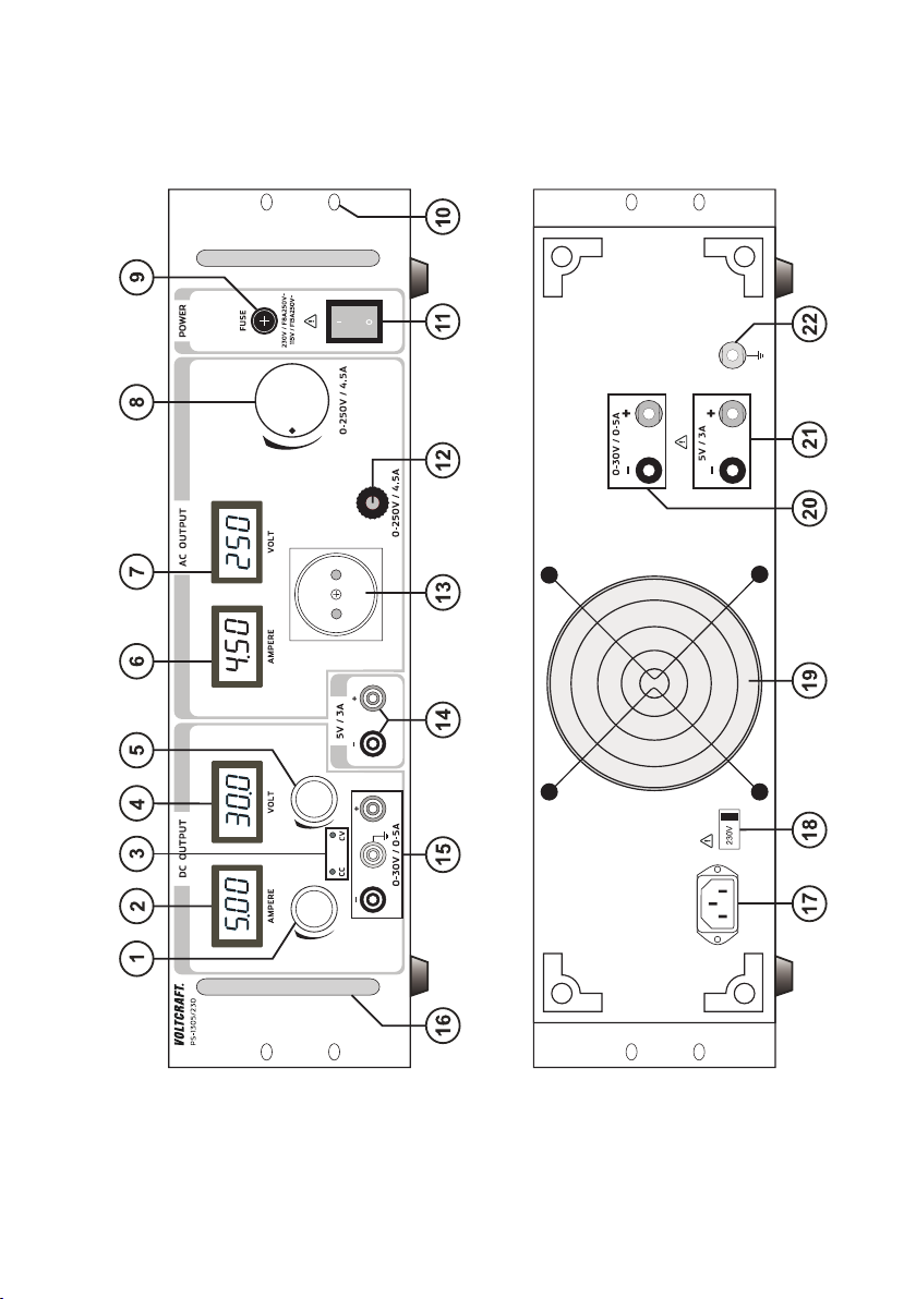
Bedienelemente
(siehe Bild auf der Ausklappseite)
(1) Einstellregler für die DC-Strombegrenzung (AMPERE = Einheit der el. Stromstärke)
(2) DC-Stromanzeige „AMPERE“
(3) DC-Statusanzeigen: „CC“ (Strombegrenzung/Konstantstrombetrieb),
„CV“ (Konstantspannungsbetrieb)
(4) DC-Spannungsanzeige „VOLT“
(5) Einstellregler für die DC-Ausgangsspannung (VOLT = Einheit der el. Spannung)
(6) AC-Stromanzeige „AMPERE“
(7) AC-Spannungsanzeige „VOLT“
(8) Einstellregler für die AC-Ausgangsspannung
(9) Netz-Eingangssicherung (Schmelzsicherung)
(10) Befestigungsöffnungen für Rack-Systeme
(11) Netzschalter zur Inbetriebnahme (I = Ein / 0 = Aus)
(12) Sicherungsautomat für AC-Ausgang
(13) Potentialfreie AC-Steckdose (ohne Schutzleiterkontakte)
(14) Festspannungsausgang 5VDC, (Pluspotential = rot „+“, Minuspotential = blau „-„)
(15) DC-Ausgang regelbar (Pluspol = rot „+“, Minuspol = blau „-„ Erdpotential = gelb/grün)
(16) Tragegriffe
(17) Schutzkontakt-Kaltgeräteanschluss für Netzkabel
(18) Eingangswahlschalter für Netzspannung. Achtung! in Europa nur 230 V!
(19) Gerätelüfter. Nicht abdecken!
(20) Rückseitiger DC-Regelausgang (Schraubklemme mit Buchsenfunktion)
(21) Rückseitiger DC-Festspannungsausgang (Schraubklemme mit Buchsenfunktion)
(22) Erdpotential. Der Anschluss ist direkt mit dem Schutzleiter am Netzstecker verbunden.
Page 8

7
Sicherheits- und Gefahrenhinweise
Bei Schäden, die durch Nichtbeachten dieser Bedienungsanleitung verursacht werden,
erlischt die Gewährleistung/Garantie! Für Folgeschäden und bei Sach- oder Personenschäden, die durch unsachgemäße Handhabung oder Nichtbeachten der Sicherheitshinweise verursacht werden, übernehmen wir keine Haftung!
Dieses Gerät hat das Werk in sicherheitstechnisch einwandfreien Zustand verlassen.
Um diesen Zustand zu erhalten und einen gefahrlosen Betrieb sicherzustellen, muss der Anwender
die Sicherheitshinweise und Warnvermerke beachten, die in dieser Gebrauchsanweisung enthalten
sind. Folgende Symbole gilt es zu beachten:
Ein in einem Dreieck befindliches Ausrufezeichen weist auf wichtige Hinweise in dieser
Bedienungsanleitung hin, die unbedingt zu beachten sind.
Ꮨ
Ein Blitzsymbol im Dreieck warnt vor einem elektrischen Schlag oder der Beeinträchtigung
der elektrischen Sicherheit des Geräts.
☞
Das „Hand“-Symbol ist zu finden, wenn Ihnen besondere Tipps und Hinweise zur Bedienung gegeben werden sollen.
Nur zur Verwendung in trockenen Innenbereichen
Dieses Gerät ist CE-konform und erfüllt die erforderlichen nationalen und europäischen
Richtlinien.
Schutzleiteranschluss; diese Schraube darf nicht gelöst werden
Erdpotential, Massepotential
Elektrogeräte und Zubehör sind keine Spielzeuge und gehören nicht in Kinderhände!
In gewerblichen Einrichtungen sind die Unfallverhütungsvorschriften des Verbandes der gewerblichen
Berufsgenossenschaften für elektrische Anlagen und Betriebsmittel zu beachten.
In Schulen und Ausbildungseinrichtungen, Hobby- und Selbsthilfewerkstätten ist der Umgang mit
Netzgeräten durch geschultes Personal verantwortlich zu überwachen.
Achten Sie darauf, dass ihre Hände, Schuhe, Kleidung, der Boden und das Netzgerät unbedingt
trocken sind.
Beim Öffnen von Abdeckungen oder entfernen von Teilen, außer wenn dies von Hand möglich ist, können spannungsführende Teile freigelegt werden.
Vor einem Öffnen, muss das Gerät von allen Spannungsquellen getrennt werden.
Kondensatoren im Gerät können noch geladen sein, selbst wenn das Gerät von allen Spannungs-
quellen getrennt wurde.
°
Page 9

8
Schalten Sie das Labornetzgerät niemals gleich dann ein, wenn es von einem kalten in einen warmen
Raum gebracht wird. Das dabei entstandene Kondenswasser kann unter ungünstigen Umständen Ihr
Gerät zerstören. Lassen Sie das Gerät uneingeschaltet auf Zimmertemperatur kommen.
Das Netzgerät erwärmt sich bei Betrieb; Achten Sie auf eine ausreichende Belüftung. Lüftungsschlitze
dürfen nicht abgedeckt werden!
Setzen Sie das Gerät keinem direkten Sonnenlicht aus. Heizquellen sind in unmittelbarer Nähe zu vermeiden. Das Gerät könnte sich zu stark aufheizen.
Netzgeräte und die angeschlossenen Verbraucher dürfen nicht unbeaufsichtigt betrieben werden.
Stellen Sie z.B. keine mit Flüssigkeit gefüllten Gefäße, Vasen oder Pflanzen auf oder neben das Netz-
gerät. Ein Umfallen kann das Gerät zerstören, außerdem besteht höchste Gefahr eines Brandes.
Bei Arbeiten mit Netzgeräten ist das Tragen von metallischem oder leitfähigem Schmuck wie Ketten,
Armbändern, Ringen o.ä. verboten.
Das Netzgerät ist nicht für die Anwendung an Menschen und Tieren zugelassen.
Setzen Sie das Gerät keinen mechanischen Beanspruchungen aus. Bereits der Fall aus geringer
Höhe kann das Gerät beschädigen. Vibrationen sind zu vermeiden.
Wenn anzunehmen ist, dass ein gefahrloser Betrieb nicht mehr möglich ist, so ist das Gerät außer
Betrieb zu setzen und gegen unbeabsichtigten Betrieb zu sichern. Es ist anzunehmen, dass ein
gefahrloser Betrieb nicht mehr möglich ist, wenn:
- das Gerät sichtbare Beschädigungen aufweist,
- das Gerät nicht mehr arbeitet und
- nach längerer Lagerung unter ungünstigen Verhältnissen oder
- nach schweren Transportbeanspruchungen.
Beachten Sie auch die Sicherheitshinweise in den einzelnen Kapiteln bzw. in den Bedienungsanlei-
tungen der angeschlossenen Geräte.
Funktionsbeschreibung
Das DC-Labornetzgerät ist linear geregelt und weist sehr geringe Restwelligkeiten auf. Alle Gleichspannungsausgänge sind potentialfrei und weisen eine Schutztrennung gegenüber der Netzspannung
auf. Sekundärseitig erfolgt der DC-Anschluss jeweils über farbige Sicherheits-Buchsen an der Vorderseite und Schraubklemmen mit Buchse an der Rückseite.
Die Spannungs- und Stromanzeige (V = Volt = Einheit der elektrischen Spannung, A = Ampere = Einheit der elektrischen Stromstärke) erfolgt in separaten Displays.
Diverse Schutzmechanismen, z.B. Überlastschutz und Strombegrenzung etc. sind für den sicheren
und zuverlässigen Betrieb eingebaut.
Die Kühlung des Netzgerätes erfolgt über einen Lüfter. Auf eine ausreichende Luftzirkulation ist deshalb zu achten.
Am Netzgerät kann die Ausgangsspannung und der Ausgangsstrom stufenlos eingestellt werden.
Der AC-Trennstelltrafo weist eine galvanische Trennung zwischen Primär- und Sekundärseite auf. Die
Netzspannung wird über einen Trenntrafo potentialfrei entkoppelt und anschließend über einen Stelltrafo geregelt. Über den gesamten Einstellbereich steht so der max. Strom von 4,5 Azur Verfügung.
Page 10

9
Am AC-Ausgang darf aus Sicherheitsgründen immer nur 1 Gerät angeschlossen
werden.
Inbetriebnahme
Das Labornetzgerät ist kein Ladegerät. Verwenden Sie zum Laden von Akkus geeignete Ladegeräte mit entsprechender Ladeabschaltung.
Bei längerem Betrieb mit Nennlast wird die Gehäuseoberfläche warm. Achtung! Mögliche Verbrennungsgefahr! Achten Sie daher unbedingt auf eine ausreichende Belüftung
des Netzgerätes und betreiben Sie es niemals teilweise oder ganz abgedeckt, um eventuelle Schäden zu vermeiden.
Achten Sie beim Anschluss eines Verbrauchers unbedingt darauf, dass dieser im
nicht eingeschalteten Zustand angeschlossen wird. Ein eingeschalteter Verbraucher
kann beim Anschluss an die Ausgangsbuchsen des Netzgerätes zu einer Funkenbildung führen, welche wiederum die Buchsen bzw. die angeschlossenen Leitungen
und/oder deren Klemmen beschädigen können.
Wenn Sie Ihr Netzgerät nicht benötigen, schalten Sie es aus und trennen es vom
Netz. Die Anzeigen bleiben nach dem Ausschalten noch einige Sekunden an, um die
internen Kondensatoren zu entladen.
Auf einen ausreichenden Leiterquerschnitt der Anschlussleitungen ist unbedingt zu
achten, da eine Überlastung zum Leitungsbrand führen kann.
Auswahl der Netzspannung
Das Labornetzgerät kann wahlweise mit 115 V oder mit 230 V/AC betrieben werden.
Stellen Sie vor der Erstinbetriebnahme sicher, dass sich der rückseitige Netzspannungs-Wahlschalter (18) in der richtigen Position befindet. In Europa beträgt die Netzspannung zwischen 220 und 240 V/AC. Stellen Sie den Umschalter mit einem Schraubendreher in Position „230 V“.
Anschluss des Netzkabels
Verbinden Sie das beiliegende Schutzkontakt-Netzkabel mit dem Kaltgeräte-Einbaustecker (17) am
Netzgerät. Achten Sie auf festen Sitz.
Verbinden Sie das Netzkabel mit einer Schutzkontakt-Steckdose mit Schutzerdung.
Aufstellen des Gerätes
Stellen Sie das Labornetzgerät auf eine stabile, ebene und unempfindliche Oberfläche ab. Achten Sie
darauf, dass die Lüftungsschlitze im Gehäuse nicht verdeckt werden.
Page 11

10
Ausgangsspannung von Ausgang „DC OUTPUT“ einstellen
Entfernen Sie angeschlossene Verbraucher von Ausgang „DC OUTPUT (15).
Schalten Sie das Netzgerät über den Betriebsschalter (11) ein. Der Schalter leuchtet und im Display
erscheint die Spannungs- und Stromanzeige.
Stellen Sie den Stromeinstellregler „AMPERE“ (1) in Mittelstellung.
Über den Drehregler „VOLT“ (5) kann die Ausgangsspannung eingestellt werden.
Die Ausgangsspannung wird imDisplay „VOLT“ (4) angezeigt.
☞
Im normalen Betrieb arbeitet das Gerät im Konstantspannungsmodus. Das heißt, das
Netzgerät gibt eine konstante voreingestellte Ausgangsspannung ab. Dieser Betrieb wird
mit der Statusanzeige „CV“ (3) signalisiert.
Strombegrenzung von Ausgang „DC OUTPUT“ einstellen
Die Begrenzung des Ausgangsstromes ist ein Schutzmechanismus, um den Verbraucher oder die
Anschlussleitungen zu schützen. Die Strombegrenzung kann nur mit einem Kurzschluss am Ausgang
kontrolliert werden. Das Netzgerät liefert dann maximal den voreingestellten Strom.
Entfernen Sie angeschlossene Verbraucher von Ausgang „DC OUTPUT“ (15).
Schalten Sie das Netzgerät über den Betriebsschalter (11) ein. Der Schalter leuchtet und im Display
erscheint die Spannungs- und Stromanzeige.
Drehen Sie den Stromregler „AMPERE“ (1) ganz nach links.
Verbinden Sie die Ausgangsbuchsen „+“ und „-„ (15) mit einem Verbindungskabel (mind. 1,0 mm
2
).
Der Ausgang wird kurzgeschlossen. Im Display „AMPERE“ (2) kann der Stromwert abgelesen werden.
Die Anzeige „CC“ leuchtet während der Einstellung.
Über den Drehregler „AMPERE“ (1) kann die max. Stromstärke (Strombegrenzung) eingestellt werden.
Entfernen Sie nach erfolgter Einstellung die Kurzschlussbrücke. Das Display zeigt wieder die tatsäch-
liche Stromstärke (bei unbelastetem Ausgang 0,00 A). Die Statusanzeige „CV“ leuchtet.
Wird die voreingestellte Stromstärke im Normalbetrieb erreicht, schaltet das Netzgerät in den Strom-
begrenzungsmodus und reduziert dabei den Spannungswert. Dieser Betrieb wird mit der roten Statusanzeige „CC“ (3) signalisiert.
Ausgangsspannung von Ausgang „AC OUTPUT“ einstellen
Entfernen Sie angeschlossene Verbraucher von Ausgang „AC OUTPUT (13).
Schalten Sie das Netzgerät über den Betriebsschalter (11) ein. Der Schalter leuchtet und im Display
erscheint die Spannungs- und Stromanzeige.
Über den Drehregler (8) kann die Ausgangsspannung eingestellt werden.
Im Display „VOLT“ (7) wird die Ausgangsspannung angezeigt, im Display „AMPERE“ (6) wird der ent-
nommene Ausgangsstrom angezeigt.
☞
Der max. Ausgangsstrom ist auf 4,5 A begrenzt. Bei Überschreitung löst der Sicherungsautomat (12) aus. Der rote Stift des Sicherungsautomaten wird herausgedrückt.
Kontrollieren Sie in diesem Fall die Nennlast des Verbrauchers und drücken den Stift nach
einer kurzen Abkühlphase von ca. 10 Minuten wieder in den Automaten.
Page 12
11
Der AC-Ausgang darf nicht parallel oder in Reihe geschaltet werden. Die Verschaltung mit anderen Netzgeräten oder Netzspannung ist nicht zulässig.
Anschluss eines Verbrauchers
Achten Sie beim Anschluss eines Verbrauchers darauf, dass dieser uneingeschaltet
mit dem Netzgerät verbunden wird. Die max. Stromaufnahme des anzuschließenden
Verbrauchers darf die Angaben in den technischen Daten nicht überschreiten.
Bei der Reihenschaltung der DC-Ausgänge mehrerer Netzgeräte können berührungsgefährliche Spannungen(> 75 VDC) erzeugt werden, welche bei Berührung lebensgefährlich sein können. Ab dieser Spannung darf nur schutzisoliertes Zubehör
(Anschlussleitungen, Messleitungen etc.) verwendet werden.
Die Verwendung metallisch blanker Leitungen und Kontakte ist im DC-Bereich zu
vermeiden. Alle diese blanken Stellen sind durch geeignete, schwer entflammbare
Isolierstoffe oder andere Maßnahmen abzudecken und vor direkter Berührung und
Kurzschluss zu schützen.
Im AC-Bereich ist ab einer Spannung >50 V die Verwendung schutzisolierter Leitungen und Anschlusskabel vorgeschrieben.
Achten Sie auf einen ausreichenden Leiterquerschnitt für die vorgesehene Stromstärke.
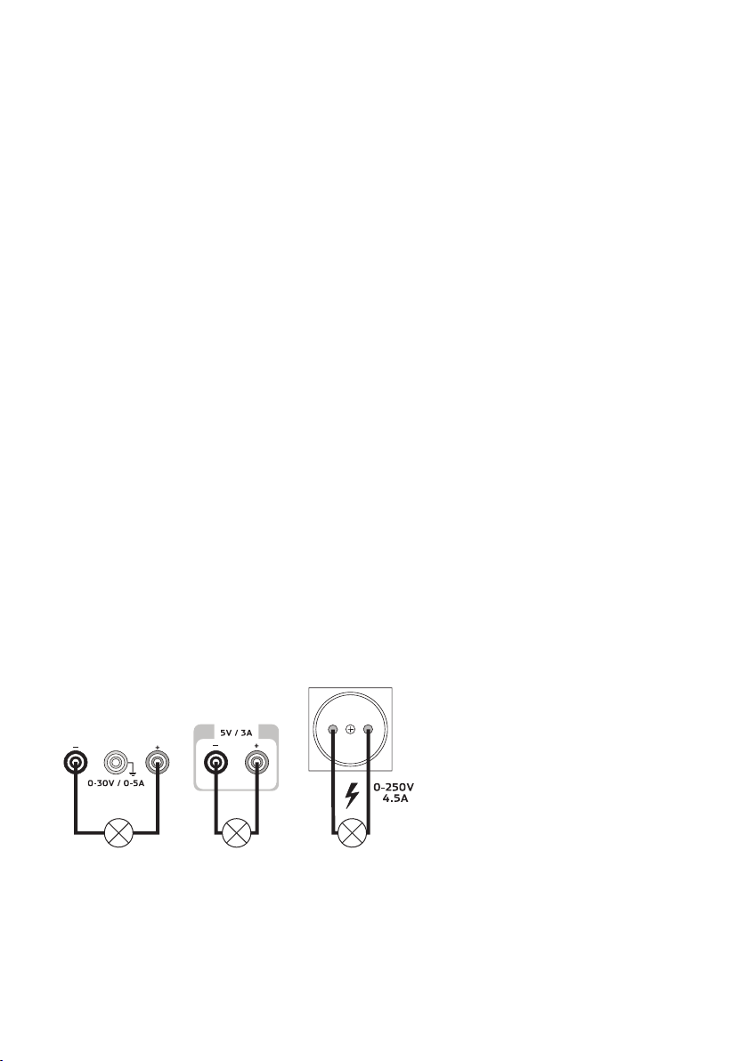
Am Netzgerät sind die DC-Ausgänge doppelt vorhanden (15 und 20 sowie 14 und 21). Diese Ausgänge sind miteinander Verbunden und führen immer die selbe Ausgangsspannung.
Entfernen Sie angeschlossene Verbraucher vom Ausgang.
Schalten Sie das Netzgerät über den Betriebsschalter (1) ein. Die Betriebsanzeige (2/3) leuchtet und
im Display erscheint die Spannungs- und Stromanzeige.
Stellen Sie die Parameter nach Ihren Vorgaben wie im Kapitel „Inbetriebnahme“ beschrieben ein.
Kontrollieren Sie nochmals die korrekt eingestellte Ausgangsspannung.
Verbinden Sie den Verbraucher wie abgebildet mit dem entsprechenden Ausgang. Beachten Sie bei
den beiden DC-Ausgängen die Polarität (+ und -)
Der angeschlossene Verbraucher kann jetzt eingeschaltet werden.
☞
Die Stromaufnahme des angeschlossenen Verbrauchers wird im Display (2 und 6) in
Ampere (A) angezeigt. Der mittlere Festspannungsausgang hat keine Anzeige für Spannung und Strom.
Page 13

12
Entsorgung
Elektronische Altgeräte sind Wertstoffe und gehören nicht in den Hausmüll. Ist das Gerät
am Ende seiner Lebensdauer, so entsorgen Sie es nach den geltenden gesetzlichen
Bestimmungen bei den kommunalen Sammelstellen. Eine Entsorgung über den Hausmüll
ist untersagt.
Wartung und Reinigung
Bis auf eine gelegentliche Reinigung oder einen Sicherungswechsel ist das Labornetzgerät wartungsfrei. Zur Reinigung des Gerätes nehmen Sie ein sauberes, fusselfreies, antistatisches und trockenes
Reinigungstuch ohne scheuernde, chemische und lösungsmittelhaltige Reinigungsmittel.
Primäre Netzsicherung wechseln
Lässt sich das Labornetzgerät nicht mehr einschalten, so ist vermutlich die primäre Netzsicherung (9)
defekt.
Zum Auswechseln der Netzsicherung gehen Sie wie folgt vor:
Schalten Sie das Netzgerät aus und entfernen alle Anschlusskabel und den Netzstecker vom Gerät.
Schrauben Sie den Sicherungseinsatz mit einem geeigneten Schraubendreher aus der Halterung.
Ersetzen Sie die defekte Sicherung gegen eine neue Feinsicherung (5x20 mm) des selben Typs und
Nennstromstärke. Den Sicherungswert finden Sie im Kapitel „Technische Daten“
Schrauben Sie den Sicherungseinsatz in den Sicherungshalter.
Page 14

13
Behebung von Störungen
Mit dem Labornetzgerät haben Sie ein Produkt erworben, welches zuverlässig und betriebssicher ist.
Dennoch kann es zu Problemen oder Störungen kommen.
Hier möchten wir Ihnen beschreiben, wie Sie mögliche Störungen leicht selbst beheben können:
Beachten Sie unbedingt die Sicherheitshinweise!
Fehler Mögliche Ursache
Das Netzgerät lässt sich nicht Leuchten am Netzgerät die Anzeigen (2/4/6/7) ?
einschalten. Kontrollieren Sie die Netzspannung (evtl. Netzsicherung im
Gerät bzw. Leitungsschutzschalter überprüfen).
Angeschlossene Verbraucher Ist die korrekte Spannung eingestellt ?
funktionieren nicht. Ist die Polarität korrekt ?
Kontrollieren Sie die techn. Daten der Verbraucher.
Kontrollieren Sie die Sekundärsicherung (12) am AC-Ausgang
Die „CC“-Anzeige (3) leuchtet. DC-Konstantstrombetrieb
Die voreingestellte Stromstärke wurde überschritten.
Kontrollieren Sie die Stromaufnahme an Ihrem Verbraucher und
erhöhen Sie ggf. die Strombegrenzung am Netzgerät.
Die „CV“-Anzeige (3) leuchtet Konstantspannungsbetrieb
Das Netzgerät arbeitet normal. Am Ausgang wird die
eingestellte, konstante Spannung ausgegeben.
Überprüfen Sie regelmäßig die technische Sicherheit des Gerätes z.B. auf Beschädigung des Gehäuses usw.
Sicherungen sind Ersatzteile und werden nicht durch die Gewährleistung/Garantie
abgedeckt.
Andere Reparaturen als zuvor beschrieben sind ausschließlich durch eine autorisierte Fachkraft durchzuführen. Sollten Sie Fragen zum Umgang des Gerätes haben,
steht Ihnen unser Techn. Support unter folgender Telefonnummer zur Verfügung:
Voltcraft®, 92242 Hirschau, Lindenweg 15, Tel.-Nr. 0180 / 586 582 7.
Page 15

14
Technische Daten
Ausgang 1 Ausgang 2 Ausgang 3
Ausgangsdaten 0 - 30 V/DC, 0 - 5 A 5 V/DC max. 3 A 0 - 250 V/AC max. 4,5 A
Displaygenauigkeit „VOLT“ +/-(0,2 % +/-(1 % der Ablesung
der Ablesung + 2 Counts)
+ 2 Counts)
Displaygenauigkeit „AMPERE“
+/-(1 % der +/-(1 % der Ablesung
Ablesung + 2 Counts)
+ 2 Counts)
Genauigkeit +/-2,5%
DC-Festspannungsausgang
Restwelligkeit 1 mVrms 10 mV
3 mArms
Regelverhalten bei 100% 5 mV 10 mV
Laständerung 7 mA
Regelverhalten bei 3 mV 10 mV
Netzschwankung 5 mA
Betriebsspannung 110 - 127 V/AC (+/- 10%) oder 220 - 240 V/AC (+/- 10%)
Leistungsaufnahme 1500 W
Netzsicherung 115 V: F15A250V
Flink (5 x 20 mm) 230 V: F8A250V
Betriebstemperatur 0 bis +40 °C
Rel. Luftfeuchtigkeit 10 - 80%, nicht kondensierend
Schutzklasse (Primärseitig) 1
Netzanschluss IEC 320 C14, Kaltgeräte-Einbaustecker
Gewicht 26 kg
Abmessungen 480 x 137 x 427
(B x H x T) mm
Betriebshöhe max. 2000 m über Meereshöhe (N.N.)
Page 16

15
Introduction
Dear Customer,
Thank you for making the excellent decision to purchase this Voltcraft® product.
You have acquired an above-average quality product from a brand family which has distinguished itself in the field of measuring, charging and network technology through its expertise and permanent
innovation.
With Voltcraft®, you will be able to cope even with difficult tasks as an ambitious hobbyist or as a professional user. Voltcraft® offers reliable technology with an exceptional cost-performance ratio.
Therefore, we are absolutely sure: your investment in a Voltcraft product will also be the start
of a long and good partnership.
Enjoy your new Voltcraft® product!
Table of Contents
Introduction . . . . . . . . . . . . . . . . . . . . . . . . . . . . . . . . . . . . . . . . . . . . . . . . . . . . . . . . . . . . . . . . . . . . .15
Package contents . . . . . . . . . . . . . . . . . . . . . . . . . . . . . . . . . . . . . . . . . . . . . . . . . . . . . . . . . . . . . . . .15
Intended Use . . . . . . . . . . . . . . . . . . . . . . . . . . . . . . . . . . . . . . . . . . . . . . . . . . . . . . . . . . . . . . . . . . . .16
Operating Controls . . . . . . . . . . . . . . . . . . . . . . . . . . . . . . . . . . . . . . . . . . . . . . . . . . . . . . . . . . . . . . .17
Safety and Hazard Notices . . . . . . . . . . . . . . . . . . . . . . . . . . . . . . . . . . . . . . . . . . . . . . . . . . . . . . . . .18
Functional Description . . . . . . . . . . . . . . . . . . . . . . . . . . . . . . . . . . . . . . . . . . . . . . . . . . . . . . . . . . . .19
Getting Started . . . . . . . . . . . . . . . . . . . . . . . . . . . . . . . . . . . . . . . . . . . . . . . . . . . . . . . . . . . . . . . . . . .20
Selecting the Grid Voltage . . . . . . . . . . . . . . . . . . . . . . . . . . . . . . . . . . . . . . . . . . . . . . . . . . . . . . . . .20
Connecting the Power Cable . . . . . . . . . . . . . . . . . . . . . . . . . . . . . . . . . . . . . . . . . . . . . . . . . . . . . . .20
Unit Installation . . . . . . . . . . . . . . . . . . . . . . . . . . . . . . . . . . . . . . . . . . . . . . . . . . . . . . . . . . . . . . . . .20
Setting the Output Voltage of Output “DC OUTPUT” . . . . . . . . . . . . . . . . . . . . . . . . . . . . . . . . . . . .21
Setting the Current Limitation of Output “DC OUTPUT” . . . . . . . . . . . . . . . . . . . . . . . . . . . . . . . . . .21
Setting the Output Voltage of Output “AC OUTPUT” . . . . . . . . . . . . . . . . . . . . . . . . . . . . . . . . . . . . .21
Connecting a Consumer . . . . . . . . . . . . . . . . . . . . . . . . . . . . . . . . . . . . . . . . . . . . . . . . . . . . . . . . . .22
Disposal . . . . . . . . . . . . . . . . . . . . . . . . . . . . . . . . . . . . . . . . . . . . . . . . . . . . . . . . . . . . . . . . . . . . . . . .23
Maintenance and Cleaning . . . . . . . . . . . . . . . . . . . . . . . . . . . . . . . . . . . . . . . . . . . . . . . . . . . . . . . . .23
Exchanging the Primary Fuse . . . . . . . . . . . . . . . . . . . . . . . . . . . . . . . . . . . . . . . . . . . . . . . . . . . . . .23
Troubleshooting . . . . . . . . . . . . . . . . . . . . . . . . . . . . . . . . . . . . . . . . . . . . . . . . . . . . . . . . . . . . . . . . . .24
Technical Data . . . . . . . . . . . . . . . . . . . . . . . . . . . . . . . . . . . . . . . . . . . . . . . . . . . . . . . . . . . . . . . . . . .25
Package contents
Laboratory power unit
Cable with grounding contact
Operating instructions
Page 17

16
Intended Use
The laboratory power unit is a combination of direct current power unit and safety variable isolating transformer with alternating current output. The device can be set up as a table device or integrated into rack
systems.
The DC voltage source is used for operating low-voltage consumers. Avariable output with adjustable
voltage and current and a fixed voltage output with fixed current limitation are available. Connection is
possible on the front and rear alike.
The AC variable isolating transformer serves as galvanic separator for work on grid-voltage powered
electrical devices. The AC output voltage can be adjusted infinitely.
When switching the DC outputs of several DC power units in series, voltages of >75 V/DC, which are dangerous to contact, may be generated. At the AC output, voltages of >50 V/AC can be generated accordingly. Starting at these voltages, insulated lines/measuring cables must be used for safety reasons.
DC connection on the front is performed with 4 mm safety sockets, on the rear with socket screw
connectors. The outputs (front and back) are connected to each other.
The AC output is connected through a potential-free socket without grounding contact. For measuring
purposes, suitable measuring adapters must be used.
Only 1 device at a time may be connected to the AC output. Never use any multiple
outlets, since the grid voltage can be transferred to the other devices through the
grounding contact in case of an error. Danger to life!
Unisolated lines or open contacts must be avoided under all circumstances. Danger
of electrical shock when touching two live conductors!
The connection cables used must be large enough. Where the conductor section is
too small, overheating and fire may result.
The output data is as follows:
Output 1 “DC OUTPUT” 0 - 30 VDC, 0 - 5 A
Output 2 “5V/3A”. 5 VDC max. 3 A
Output 3 “AC OUTPUT” 0 - 250 VAC max. 4.5 A(max. 1125 VA)
The voltage and current on output 1 and current on output 3 can be set infinitely variable through the
rotary control. The values are displayed on the respective LC displays.
The device is overload- and short-circuit-protected. The alternate voltage output is protected by a circuit breaker.
The laboratory power unit is designed in compliance with protection class 1. It is only approved for
connection to shockproof sockets with protective grounding and an alternating current of 230V/AC
commonly used in households. All outputs are potential-free.
Operation is impermissible under unfavourable ambient conditions. Unfavourable ambient conditions are:
- moistness or high humidity
- dust and combustible gases, vapours or solvents
- thunderstorms or similar conditions such as strong electrostatic fields etc.
Any use other than that described above will damage the product and may involve other risks, such as
short-circuit, fire, electric shock, etc. Do not change or modify any part of the product!
The safety instructions must be observed under all circumstances!
Page 18

17
Operating Controls
(see figure on the fold-out page)
(1) DC current limiter control (AMPERE = unit of el. current)
(2) DC current display “AMPERE”
(3) DC status displays: “CC” (Current limitation/constant current operation),
“CV” (Constant voltage operation)
(4) DC voltage display “VOLT”
(5) DC output voltage control (VOLT = unit of el. voltage)
(6) AC current display “AMPERE”
(7) AC voltage display “VOLT”
(8) AC output voltage control
(9) Mains/input fuse (melting fuse)
(10) Fastening apertures for rack systems
(11) Power switch for putting the device into operation (I=ON / 0=OFF)
(12) Circuit breaker for AC output
(13) Potential-free AC socket (no grounding contacts)
(14) Fixed voltage output 5VDC, (positive potential = red “+”, negative potential = blue “-”)
(15) DC-output adjustable (plus pole = red “+”, minus pole = blue “-” ground potential = yellow/green)
(16) Carrying handles
(17) Grounded low-power connection for mains cable
(18) Input selector switch for mains voltage. Attention! In Europe only 230 V!
(19) Device fan. Do not cover!
(20) Rear DC control output (terminal screw clamp)
(21) Rear DC fixed voltage output (terminal screw clamp)
(22) Ground potential. The connection is directly connected with the grounding conductor on the
mains plug.
Page 19

18
Safety Instructions and Hazard Warnings
The guarantee/warranty will be void if damage is incurred resulting from non-compliance
with the operating instructions. We do not accept liability for damage to property or personal injury caused by misuse or non-compliance with the safety instructions!
This device left the factory in a safe and perfect condition.
We kindly request that you as a user observe the safety instructions and warnings contained in this
operating manual to preserve this condition and to ensure safe operation! Please pay attention to the
following symbols:
An exclamation mark in a triangle indicates important information in these operating
instructions which are to be followed strictly.
Ꮨ
The lightning symbol in a triangle warns against an electric shock or the impairment of the
electrical safety of the appliance.
☞
The “hand” symbol indicates special information and advice on operation of the device.
Only for use in dry interior environments
This product has been CE-tested and meets the necessary European guidelines.
Grounding wire connection; this screw may not be loosened.
Earth potential, ground potential
Electrical appliances and accessories are no toys and have no place in the hands of children.
On industrial sites, the accident prevention regulations of the association of the industrial workers’
society for electrical equipment and utilities must be followed.
Power units used at schools, training facilities, do-it-yourself and hobby workshops should not be
handled unless supervised by trained, responsible personnel.
Please make sure that your hands, your shoes, your clothing, the floor and the power unit are dry.
Live components may be exposed if covers are opened or parts are removed unless this can be done
by hand.
Before opening it, disconnect the device from all voltage sources.
Capacitors inside the device may still be charged, even if the device has been disconnected from all
voltage sources.
Do not switch the laboratory power unit on immediately after it has been taken from a cold to a warm
environment. Under adverse conditions, the resulting condensation could destroy the device. Allow the
device to reach room temperature before switching it on.
°
Page 20

19
The power unit generates heat during operation; ensure that it is adequately ventilated. Do not cover
the ventilation apertures of the device!
Never expose the device to any direct sunlight. Avoid heat sources in direct proximity. The device
might overheat.
Do not leave power units and connected consumer devices in operation unattended.
Do not place any containers filled with liquid, e.g. vases or plants, on or next to the power unit. If they
fall over, the device can be destroyed and there is a great risk of fire.
When working with power supplies, wearing metallic or conductive jewellery, such as necklaces, bra-
celets, rings etc., is prohibited.
The power unit is not designed for use on humans or animals.
Never expose the device to mechanical stress. Dropping the device even from a low height may dama-
ge it! Avoid vibrations.
If you have reason to believe that the device can no longer be operated safely, disconnect it immedia-
tely and make sure it is not unintentionally operated. It must be assumed that safe operation is no longer possible if:
- the device shows visible damage,
- the device no longer works and
- the device was stored under unfavourable conditions for a long period of time or
- after it was exposed to extraordinary stress caused by transport.
You should also heed the additional safety instructions in each chapter of these operating instructions
as well as in the operating instructions of the connected devices.
Functional Description
The DC laboratory power unit is controlled linearly and shows very low residual ripple. All DC outputs
are isolated and feature a protective isolation towards the mains voltage. For the secondary DC
connection, there are two coloured safety sockets on the front and two terminal screw clamps on the
back.
The voltage and current values (V = Volt = unit of electric voltage, A = Ampere = unit of electric current)
are displayed in separate LC displays.
Various protective mechanisms, e.g. overload protection and current limitation, etc. are built in for
secure and reliable operation.
The power unit is cooled by a fan. Therefore, ensure sufficient air circulation.
The output voltage and output current at the power unit are infinitely variable.
The AC variable isolating transformer has galvanically isolated primary and secondary sides. The grid
voltage is uncoupled potential-free through a isolating transformer and then controlled by a variable
transformer. This way, the complete current of 4.5 Ais available throughout the adjustment range.
For safety reasons, only 1 device at a time may be connected to the AC output.
Page 21

20
Getting Started
The laboratory power unit is not a charger. To charge batteries, use suitable chargers with a charging current cut-off.
During a longer period of operation under nominal load, the surface of the housing will
heat up. Attention! Risk of burns! Therefore, make sure that there is adequate ventilation of the power unit and never operate it partly or fully covered to avoid any damage.
When connecting a consumer, ensure that it is not connected when switched on. A
switched on consumer can result in sparks when connecting to the output terminals
of the power unit, which in turn can damage the sockets or the connected cables
and/or their clamps.
If your power unit is not required, switch it off and disconnect it from the mains. The
displays remain on for a few seconds after it is switched off to unload the internal
capacitators.
Always ensure a sufficient conductor cross-section for the connection lines, since
overload may cause fire in the line.
Selecting the Grid Voltage
The laboratory power unit can be operated with either 115 V or 230 V/AC. Before initial
commissioning, ensure that the rear mains voltage selection switch (18) is in the correct
position: In Europe, the mains voltage is between 220 and 240 V/AC. Turn the switch to
the “230 V” position with a screwdriver.
Connecting the Power Cable
Connect the supplied grounding cable to the low-power device installation socket (17) on the power
unit. Ensure a tight fit.
Connect the power cable to a shockproof mains socket with protective grounding.
Unit Installation
Place the laboratory power unit on a stable, level and robust surface. Make sure that ventilation slots
in the casing are not covered up.
Page 22

21
Setting the Output Voltage of Output “DC OUTPUT”
Remove connected consumers from output “DC OUTPUT” (15).
Switch on the power unit at the power switch (11). The switch lights up and the current and voltage display appears on the display.
Put the current control “AMPERE” (1) into its central position.
Use the “VOLT” rotary control (5) to adjust the output voltage.
The output voltage is indicated in the display “VOLT” (4).
☞
In normal mode the device operates in constant voltage mode. This means that the power
unit emits a constant, preset output voltage. This operation is indicated with the “CV“ (3) status
display.
Setting the Current Limitation of Output “DC OUTPUT”
Limiting the output current is a protection mechanism to protect the consumer or connection cables.
Current limitation can only be monitored through with a short circuit at the output. The power unit then
supplies the maximum current set.
Remove connected consumers from output “DC OUTPUT” (15).
Switch on the mains power unit at the power switch (11). The switch lights up and the current and vol-
tage display appears on the display.
Turn the current control “AMPERE” (1) all the way to the left.
Connect the output socket “+” and “-” (15) with a connecting line (at least 1.0 mm
2
The output is short-
circuited. The current value can be read in the display “AMPERE”. The “CC“ display is lit during setting.
Use the “AMPERE” rotary control (1) to adjust the max. current (current limitation).
After completing your settings, remove the shorting bar. The display shows the actual current (for unlo-
aded output: 0.00 A). The status display “CV” is lit.
If the preset current is reached in normal operation, the power unit switches to current limitation mode
and reduces the voltage value. This operation is indicated with a red status display “CC“ (3).
Setting the Output Voltage of Output “AC OUTPUT”
Remove connected consumers from output “AC OUTPUT” (13).
Switch on the mains power unit with the power switch (11). The switch lights up and the current and
voltage display appears on the display.
Use the rotary control (8) to adjust the output voltage.
The “VOLT” display (7) indicates the output current, the “AMPERE” display (6) the tapped output
current.
☞
The max. output current is limited to 4.5 A. When this value is exceeded, the circuit breaker
(12) is triggered. The circuit breaker’s red pin is pressed out.
In this case, check the consumer’s nominal load and press the pin back into the circuit
breaker after a cooling-down time of approx. 10 minutes.
Page 23

22
The AC output must not be switched parallel or in sequence. Parallel switching with
other power units or mains voltage is not permissible.
Connecting a Consumer
When connecting a consumer, make sure that it is switched off when it is connected
to the power unit. The maximum current consumption of the device to be connected
must not exceed the capacity indicated in the technical specifications.
For serial connection of the DC outputs with several power supplies, the resulting
voltages can be fatal on contact (> 75 VDC). As of this voltage, you may only use insulated accessories.
Avoid the use of non-insulated metallic cables and contacts in the DC area. All these
exposed areas must be covered with suitable, flame-resistant insulation materials or
by other measures and be protected from direct contact and short circuits.
In the AC area, conductors and connection lines with protective isolation is mandatory at a voltage >50 V.
Ensure a sufficient cable diameter for the intended current.
The DC outputs on the power unit are present twice (15 and 20, or 14 and 21 respectively). These outputs are connected and always have the same output voltage.
Remove any connected consumers from the output.
Switch on the power unit at the power switch (1). The operating display (2/3) lights up and the current
and voltage display appears on the display.
• Set the parameters according to your specifications as described in the chapter “Start-Up”.
Verify again that the output voltage has been set correctly.
Connect the consumer to the respective output as indicated. Observe the polarity of the two DC out-
puts (+ and -).
Now you can switch on the connected
consumer.
☞
The current consumption of the connected consumer is displayed in Ampere (A) in the displays
(2 and 6). The middle fixed voltage output has no display for voltage and current.
Page 24

23
Disposal
Old electronic devices are recyclable and should not be disposed of in the household was-
te. At the end of its service life, dispose of the product at the community collection point
according to the relevant statutory regulations. It is prohibited to dispose of the device in
the household waste.
Maintenance and Cleaning
Apart from an occasional cleaning or exchanging the fuse, this laboratory power unit is maintenancefree. Use a clean, lint-free, antistatic and dry cloth to clean the device. Do not use any abrasive or chemical agents or detergents containing solvents.
Exchanging the Primary Fuse
If it is no longer possible to switch on the laboratory power unit, the primary mains fuse (9) is probably
defective.
Proceed as follows to replace the mains fuse:
Switch off the power unit and remove all the connection cables and the mains plug from the device.
Screw the fuse insert out of the holder with suitable screwdriver.
Replace the defective fuse with a new fine-wire fuse (5 x 20 mm) of the same type and rated current.
The fuse value is listed in the technical data.
Screw the fuse insert into the fuse holder.
Page 25

24
Troubleshooting
By purchasing the laboratory power unit, you have acquired a product that is reliable and operationally safe.
Nevertheless, problems or errors may occur.
For this reason we want to describe how to troubleshoot potential malfunctions:
Always observe the safety instructions!
Error Possible cause
The power unit cannot Are the control lamps on the power unit lit (2/4/6/7) ?
be turned on. Check the mains voltage (if required, check the mains fuse
in the device or the line circuit breaker).
Connected consumer devices Correct voltage set?
do not function. Is the polarity correct?
Check the technical data of the consumers.
Check the secondary fuse (12) at the AC output
The “CC” (3) indicator is lit. DC constant current operation
The preset current was exceeded.
Check the power consumption of your consumer and
if required, increase the current limitation at the power unit.
The “CV” (3) indicator is lit Constant current operation
The power unit works normally. The set constant voltage
is provided on the output.
Regularly check the technical safety of the device e.g. for damaged housing etc.
Fuses are replacement parts and not covered by the warranty/guarantee.
Repairs other than those described above should only be carried out by an authori-
sed specialist. If you have any questions concerning the handling of the device,
please do no hesitate to contact our Technical Support:
Voltcraft®, 92242 Hirschau, Lindenweg 15, Tel.-No. 0180 / 586,582 7.
Page 26

25
Technical Data
Output 1 Output 2 Output 3
Output data 0 - 30 V/DC, 0 - 5 A 5 V/DC max. 3 A 0 - 250 V/AC max. 4.5 A
Display accuracy “VOLT” +/-(0,2 % +/-(1 % of the readout
of the readout + 2 counts
+ 2 Counts)
Display accuracy “AMPERE“
+/-(1 % of the +/-(1 % of the readout
readout + 2 counts
+ 2 Counts)
Accuracy +/-2,5%
DC fixed voltage output
Residual amplitude 1 mVrms 10 mV
3 mArms
Control response at 100% 5 mV 10 mV
Load change 7 mA
Control response at 3 mV 10 mV
Mains fluctuation 5 mA
Operating voltage 110 - 127 V/AC (+/- 10%) or 220 - 240 V/AC (+/- 10%)
Power consumption 1500 W
Mains fuse 115 V: F15A250V
fast blowing (5 x 20 mm) 230 V: F8A250V
Operating temperature 0 to +40 °C
Rel. air humidity 10 - 80%, non-condensing
Safety class (primary side) 1
Mains Connection IEC 320 C14, Low-power device installation plug
Weight 26 kg
Dimensions 480 x 137 x 427
(W x H x D) mm
Operating height max. 2,000 m above mean sea level
Page 27

26
Introduction
Cher client,
Vous avez pris une très bonne décision en achetant ce produit Voltcraft® et nous vous en
remercions.
Vous avez acquis un produit de qualité supérieure d´une famille de marque qui se distingue par une
compétence technique, une extraordinaire performance et une innovation permanente dans le domaine de la technique de mesure, de charge et de réseau.
Voltcraft® permet de répondre aux tâches exigeantes du bricoleur ambitieux ou de l’utilisateur professionnel. Voltcraft® offre une technologie fiable avec un rapport qualité-prix particulièrement avantageux.
Nous en sommes convaincus : votre premier contact avec Voltcraft marque le début
d’une coopération longue et efficace.
Nous vous souhaitons beaucoup de plaisir avec votre nouveau produit Voltcraft® !
Table des matières
Introduction . . . . . . . . . . . . . . . . . . . . . . . . . . . . . . . . . . . . . . . . . . . . . . . . . . . . . . . . . . . . . . . . . . . . .26
Contenu de la livraison . . . . . . . . . . . . . . . . . . . . . . . . . . . . . . . . . . . . . . . . . . . . . . . . . . . . . . . . . . . .26
Utilisation conforme . . . . . . . . . . . . . . . . . . . . . . . . . . . . . . . . . . . . . . . . . . . . . . . . . . . . . . . . . . . . . .27
Eléments de commande . . . . . . . . . . . . . . . . . . . . . . . . . . . . . . . . . . . . . . . . . . . . . . . . . . . . . . . . . . .28
Consignes de sécurité et avertissements . . . . . . . . . . . . . . . . . . . . . . . . . . . . . . . . . . . . . . . . . . . . .29
Description du fonctionnement . . . . . . . . . . . . . . . . . . . . . . . . . . . . . . . . . . . . . . . . . . . . . . . . . . . . .30
Mise en service . . . . . . . . . . . . . . . . . . . . . . . . . . . . . . . . . . . . . . . . . . . . . . . . . . . . . . . . . . . . . . . . . .31
Sélection de la tension du réseau . . . . . . . . . . . . . . . . . . . . . . . . . . . . . . . . . . . . . . . . . . . . . . . . . . .31
Raccordement du cordon secteur . . . . . . . . . . . . . . . . . . . . . . . . . . . . . . . . . . . . . . . . . . . . . . . . . . .31
Installation de l’appareil . . . . . . . . . . . . . . . . . . . . . . . . . . . . . . . . . . . . . . . . . . . . . . . . . . . . . . . . . . .31
Réglage de la tension de sortie de la sortie « DC OUTPUT » . . . . . . . . . . . . . . . . . . . . . . . . . . . . .32
Réglage de la limitation de la tension de la sortie « DC OUTPUT » . . . . . . . . . . . . . . . . . . . . . . . . .32
Réglage de la tension de sortie de la sortie « AC OUTPUT » . . . . . . . . . . . . . . . . . . . . . . . . . . . . . .32
Connexion d’un appareil . . . . . . . . . . . . . . . . . . . . . . . . . . . . . . . . . . . . . . . . . . . . . . . . . . . . . . . . . .33
Branchement d’un consommateur . . . . . . . . . . . . . . . . . . . . . . . . . . . . . . . . . . . . . . . . . . . . . . . . . .34
Élimination . . . . . . . . . . . . . . . . . . . . . . . . . . . . . . . . . . . . . . . . . . . . . . . . . . . . . . . . . . . . . . . . . . . . . .34
Entretien et nettoyage . . . . . . . . . . . . . . . . . . . . . . . . . . . . . . . . . . . . . . . . . . . . . . . . . . . . . . . . . . . . .34
Dépannage . . . . . . . . . . . . . . . . . . . . . . . . . . . . . . . . . . . . . . . . . . . . . . . . . . . . . . . . . . . . . . . . . . . . . .35
Caractéristiques techniques . . . . . . . . . . . . . . . . . . . . . . . . . . . . . . . . . . . . . . . . . . . . . . . . . . . . . . . .36
Contenu de la livraison
Alimentation de laboratoire
Cordon secteur de sécurité
Notice d’utilisation
Page 28

27
Utilisation conforme
L’alimentation de laboratoire combine une alimentation à courant continu et un transformateur de sectionnement de sécurité à sortie à courant alternatif. L’appareil est disponible à poser sur une table ou à intégrer dans
un système de racks.
La source de tension CC sert au fonctionnement d’appareils à courant faible. Il est équipé d’une sortie
réglable à réglage de tension et de courant ainsi que d’une sortie de tension fixe à limitation de courant.
Le raccordement peut être effectué à l’avant ou à l’arrière.
Le transformateur de sectionnement à CA sert de sectionneur galvanique pour les travaux sur des
appareils électriques alimentés par la tension du réseau. La tension de sortie CA est réglable en continu.
Les tensions dangereuses au contact > 75 V/DC peuvent être obtenues lors d’un montage en série des sorties
CC de plusieurs alimentations CC. Des tensions de sortie CA >50 V/AC peuvent également être générées. A
partir de cette tension et pour des raisons de sécurité, il faut utiliser des fils/câbles de mesure à double isolation.
Le raccordement CC est effectué à l’avant par des prises de sécurité de 4 mm et à l’arrière par des prises à bornes vissées. Les sorties (avant et arrière) sont reliées ensemble.
La sortie CA est sous la forme d’une prise sans potentiel sans contact de conducteur de protection.
Pour les mesures, vous devez utiliser des adaptateurs de mesure adaptés.
Vous ne pouvez raccorder qu’un seul appareil à la sortie CA. Nous vous déconseillons
d’utiliser des multi-prises cas la tension de réseau peut, en cas de défaut, être transmi-
se aux autres appareils par le contact de conducteur de protection. Danger de mort !
Evitez impérativement les câbles non isolés ou les contacts ouverts. Risque de choc
électrique en cas de contact entre deux câbles conducteurs !
Vous devez utiliser des câbles de raccordement suffisamment dimensionnés. Une
section de câble sous-dimensionnée peut provoquer une surchauffe et un incendie.
Les données de sortie sont les suivantes :
Sortie 1 « DC OUTPUT »: 0 - 30 V CC, 0 - 5 A
Sortie 2 « 5 V/3 A» : 5 V CC max. 3 A
Sortie 3 « AOUTPUT » : 0 - 250 V CA max. 4,5 A (max. 1125 VA)
Le réglage de la tension et du courant de la sortie 1 et de la tension et du courant de la sortie 3 est
effectué en continu par le bouton tournant. Les valeurs sont affichées dans les écrans correspondants.
L’appareil résiste à la surcharge et aux courts-circuits. La sortie de tension alternative est protégée par
un automate à fusibles.
Le produit appartient à la classe de protection 1. Il est homologué exclusivement pour le raccordement
sur une prise de courant de sécurité avec protection par mise à la terre et une tension alternative
domestique de 230 V/CA. Les sorties sont toutes sans potentiel.
Le fonctionnement dans des conditions d’environnement défavorables est interdit. Des conditions d’environnement défavorables sont :
- Une humidité ou un taux d’hygrométrie trop élevé
- Poussière et gaz inflammables, vapeurs ou solvants.
- Orage ou conditions orageuses et champs électrostatiques puissants, etc.
Toute utilisation autre que celle décrite précédemment provoque l’endommagement de ce produit. De
plus, elle risque de provoquer des courts-circuits, des incendies, des décharges électriques, etc. L’appareil entier ne doit être ni transformé ni modifié !
Observez impérativement les consignes de sécurité !
Page 29

28
Eléments de commande
(voir illustration sur le volet rabattable)
(1) Bouton de réglage pour la limitation de courant CC (AMPERE = unité du courant électrique)
(2) Affichage de courant CC « AMPERE »
(3) Affichage de statuts CC : « CC » (limitation de courant/fonctionnement à courant constant),
« CV » (fonctionnement à tension constante)
(4) Affichage de courant CC « VOLT »
(5) Bouton de réglage pour la tension de sortie CC (VOLT = unité de la tension électrique)
(6) Affichage de courant CA «AMPERE »
(7) Affichage de tension CA « VOLT »
(8) Bouton de réglage pour la tension de sortie CA
(9) Fusible d’entrée de réseau (fusible à fusion)
(10) Ouvertures de fixation pour les systèmes de racks
(11) Commutateur principal de mise en service (I = marche / 0 = Arrêt)
(12) Automate de fusibles pour la sortie CA
(13) Prise CA sans potentiel (sans contact de conducteur de protection)
(14) Sortie de tension fixe 5 V DC, (potentiel positif = rouge « + », potentiel négatif = bleu « - »)
(15) Sortie CC réglable (potentiel positif = rouge « + », potentiel négatif = bleu « - », potentiel de terre
= jaune/vert)
(16) Poignées de transport
(17) Raccordement de courant de sécurité pour le cordon secteur
(18) Sélectionneur d’entrée pour la tension de réseau Attention ! en Europe, uniquement 230 V !
(19) Ventilateur de l’appareil. Ne pas recouvrir !
(20) Sortie de réglage CC à l’arrière (borne à vis avec fonction de prise)
(21) Sortie de tension fixe CC à l’arrière (borne à vis avec fonction de prise)
(22) Potentiel de terre. Le raccordement est relié directement à la prise réseau avec le conducteur de
protection.
Page 30

29
Consignes de sécurité et indications de danger
Tout dommage résultant d’un non-respect du présent mode d’emploi entraîne l’annulation de
la garantie ! Nous déclinons toute responsabilité pour d’éventuels dommages matériels ou
corporels dus à un maniement incorrect ou à la non observation des consignes de sécurité !
Du point de vue de la sécurité, cet appareil a quitté l’usine en parfait état.
Afin de maintenir l’appareil en bon état et d’en assurer l’utilisation correcte sans risques, l’utilisateur
doit tenir compte des consignes de sécurité et avertissements contenus dans le présent mode d’emploi. Respectez les pictogrammes suivants :
Dans ce mode d’emploi, un point d’exclamation placé dans un triangle signale les informations importantes à respecter impérativement.
Ꮨ
Le symbole de l´éclair dans le triangle met en garde contre tout risque d´électrocution ou
toute compromission de la sécurité électrique de l´appareil.
☞
Le symbole de la « main » précède les recommandations et indications d’utilisation particulières.
N’utiliser qu’à l’intérieur dans des locaux sec
Cet appareil est homologué CE et répond aux directives nationales et européennes requises.
Raccordement du conducteur de protection. Cette vis ne doit pas être desserrée.
Potentiel de terre, potentiel de masse
Les appareils électriques et les accessoires ne sont pas des jouets, ne les laissez pas à la portée des
enfants !
Dans les installations industrielles, il convient d’observer les prescriptions de prévention des accidents
relatives aux installations et aux matériels électriques des associations professionnelles.
Dans les écoles, les centres de formation, les ateliers de loisirs et de réinsertion, l’utilisation d’appareils alimentés par secteur doit être consciencieusement surveillée par un personnel qualifié pour
cette tâche.
Veillez impérativement à ce que vos mains, vos vêtements, le sol et le bloc d’alimentation soient toujours secs.
L’ouverture des capots ou le démontage des pièces risquent de mettre à nu des pièces sous tension,
sauf lorsqu’il est possible d’effectuer ces procédures manuellement.
Avant d’ouvrir l’appareil, il faut le débrancher de toutes les sources de tension.
Les condensateurs de l’appareil peuvent encore être chargés, même lorsque l’appareil a été
déconnecté de toutes les sources de tension.
°
Page 31

30
N’allumez jamais tout de suite l’alimentation de laboratoire lorsqu’elle vient d’être transportée d’un
local froid à un local chaud. L’eau de condensation qui en résulte peut, dans des conditions défavorables, détruire l’appareil. Attendez que l’appareil non branché ait atteint la température ambiante.
Le bloc d’alimentation se réchauffe durant le fonctionnement ; veillez à ce que la ventilation soit suffisante. Ne pas recouvrir les grilles d’aération !
N’exposez pas l’appareil au rayonnement direct du soleil. Evitez les sources de chaleur à proximité
immédiate. L’appareil pourrait trop s’échauffer.
Les alimentations et les appareils connectés ne doivent pas fonctionner sans surveillance.
Ne déposer aucun récipient rempli de liquides tels que des récipients, vases ou plantes sur ou à côté
de l’alimentation. S’il tombe, l’appareil peut être détruit. Il existe en outre un risque élevé d’incendie.
Il est interdit de porter tout bijou métallique ou conducteur tels que des chaînes, bracelets, bagues ou
autres quand vous travaillez avec l’alimentation.
L’alimentation n´est pas agréée pour être utilisée pour les hommes et les animaux.
Evitez d’exposer l’appareil à des sollicitations mécaniques. Une chute même d’une faible hauteur peut
endommager l´appareil. Evitez les vibrations.
Lorsque le fonctionnement sûr de l’appareil n’est plus garanti, mettez-le hors service et empêchez tou-
te remise en marche intempestive. Une utilisation sans danger n’est plus possible si :
- l’appareil présente des dommages visibles,
- l’appareil ne fonctionne plus et
- l’appareil a été stocké durant une période prolongée dans des conditions défavorables, ou
- lorsqu’il a subi de sévères contraintes liées au transport.
Respecter également les consignes de sécurité contenues dans les différents chapitres, respective-
ment dans les notices d’utilisation des appareils raccordés.
Description du fonctionnement
L’alimentation de laboratoire a un réglage linéaire et présente des ondulations résiduelles très faibles.
Toutes les sorties à tension continue sont sans potentiel et présentent un sectionnement de protection
par rapport à la tension de réseau. Côté secondaire, le raccordement CC est effectué sur des prises
de sécurité colorées à l’avant et sur des bornes à vis dotées de prises à l’arrière.
Les affichages de tension et de courant (V = Volt = unité de tension électrique, A = Ampère = unité de
courant électrique) sont effectués sur des écrans séparés.
Le produit intègre divers mécanismes de protection, tel qu’une protection contre la surcharge, une
limitation du courant, etc. afin d’assurer un fonctionnement sûr et fiable.
Le refroidissement de l’alimentation est assuré par des ventilateurs intégrés. Veillez par conséquent à
une circulation d’air suffisante.
La tension et le courant de sortie peuvent être réglés en continu sur l’alimentation.
Le transformateur de sectionnement CA est dotée d’une coupure galvanique entre le côté primaire et le
côté secondaire. La tension de réseau est désaccouplée sans potentiel par un transformateur de sectionnement puis réglée par un transformateur de réglage. Le courant maximal disponible sur la plage de
réglage est de 4,5 A.
Page 32

31
Vous ne pouvez, pour des raisons de sécurité, raccorder qu’un seul appareil à la sortie CA.
Mise en service
L’alimentation de laboratoire n’est pas un chargeur. Veuillez, pour recharger des
accumulateurs, utiliser un chargeur approprié muni d’un dispositif d’interruption de
charge correspondant.
La surface du boîtier chauffe lors d’un fonctionnement prolongé à une charge nominale.
Attention ! Eventuels risques de brûlures ! Veillez donc impérativement à une ventilation suffisante de l´alimentation et n’utilisez jamais l´appareil partiellement ou entièrement couvert, afin d´éviter tout dommage éventuel.
Veillez à mettre les appareils hors service lors de leur branchement à l’alimentation.
Un appareil en service peut provoquer une formation d’étincelles lors du branchement aux prises de sortie de l’alimentation, ce qui peut endommager les prises ainsi
que les câbles connectés et ou leurs bornes.
En cas d’inutilisation de votre alimentation, débranchez-la du secteur. Les affichages restent allumés quelques secondes après l’arrêt pour décharger les condensateurs internes.
Veillez impérativement à utiliser des câbles de raccordement de section suffisante,
une surcharge pouvant provoquer un incendie.
Sélection de la tension du réseau
L’alimentation peut fonctionner avec du 115 V ou du 230 V/AC. Assurez-vous, avant la
première mise en service, que le sélectionneur de tension de réseau (18) à l’arrière de
l’alimentation se trouve dans la bonne position. La tension de réseau est en Europe
comprise entre 220 et 240 V/CA. Mettez le sélectionneur sur la position « 230 V », à l’aide d’un tournevis.
Raccordement du cordon secteur
Branchez le cordon secteur de sécurité fourni sur la fiche intégrée (17) de l´alimentation. Veillez à ce
que le branchement soit solide.
Branchez le cordon secteur à une prise de courant de sécurité avec protection par mise à la terre.
Installation de l’appareil
Placez l´alimentation de laboratoire sur une surface stable, plane et non fragile. Veillez à ne pas recouvrir les fentes d’aération du boîtier.
Page 33

32
Réglage de la tension de sortie de la sortie « DC OUTPUT »
Retirez les appareils connectés de la sortie « DC OUTPUT » (15).
Mettez l’alimentation en marche à l’aide de l’interrupteur de service (11). L’interrupteur s’allume et
l’écran affiche la tension et le courant.
Positionnez le bouton de réglage du courant « AMPERE » (1) en position médiane.
Vous pouvez régler la tension de sortie à l’aide du bouton tournant « VOLT » (5).
La tension de sortie est affichée sur l’écran « VOLT » (4).
☞
En fonctionnement normal, l’appareil fonctionne en mode de tension constante. C’est-àdire que l’alimentation fournit une tension de sortie préréglée constante. Ce mode de
fonctionnement est signalé par l’indicateur d’état vert « CV » (3).
Réglage de la limitation de courant de la sortie « DC OUTPUT »
Le réglage du courant de sortie est un mécanisme de protection pour protéger l’appareil ou les câbles
de raccordement. La limitation de courant ne peut être contrôlée qu’avec un court-circuit en sortie.
L’alimentation fournit alors le courant préréglé maximal.
Retirez les appareils connectés de la sortie « DC OUTPUT » (15).
Mettez l’alimentation en marche à l’aide de l’interrupteur de service (11). L’interrupteur s’allume et
l’écran affiche la tension et le courant.
Tournez le bouton tournant « AMPERE » (1) complètement vers la gauche.
Raccordez les prises de sortie « + » et « - » (15) à l’aide d’un câble de liaison (au moins 1,0 mm
2
). La
sortie est alors court-circuitée. Vous pouvez lire la valeur de courant sur l’écran «AMPERE » (2). L’affichage « CC » s’allume pendant le réglage.
Vous pouvez régler le courant maximal (limitation de courant) à l’aide du bouton tournant «AMPERE » (1).
Une fois le réglage terminé, enlevez le shunt de court-circuit. L’écran affiche de nouveau l’intensité de
courant réelle (en cas d’une sortie désactivée 0,00 A). L’indicateur d’état « CV » s’allume.
Si l’intensité de courant préréglée est atteinte en fonctionnement normal, l’alimentation passe en
mode de limitation de courant et réduit alors la valeur de tension. Ce mode de fonctionnement est signalé par l’indicateur d’état rouge « CC » (3).
Réglage de la tension de sortie de la sortie « AC OUTPUT »
Retirez les appareils connectés de la sortie « AC OUTPUT » (13).
Mettez l’alimentation en marche à l’aide de l’interrupteur de service (11). L’interrupteur s’allume et
l’écran affiche la tension et le courant.
Vous pouvez régler la tension de sortie à l’aide du bouton tournant (8).
La tension de sortie est affichée sur l’écran « VOLT » (7), le courant de sortie mesuré est affiché sur
l’écran « VOLT » (6).
☞
Le courant de sortie maximal est limité à 4,5 A. Lors d’un dépassement, l’automate de fusibles (12) déclenche. Le bouton rouge de l’automate de fusibles est sorti.
Contrôlez, dans ce cas la charge nominale de l’appareil et rentrez le bouton dans l’automate, après une pause de refroidissement d’environ 10 minutes.
Page 34

33
La sortie CA ne doit pas être raccordée en parallèle, ni en série. Le raccordement à
d’autres alimentations ou tension de réseau est interdite.
Branchement d’un consommateur
Veillez à mettre les appareils hors service lors de leur branchement à l’alimentation.
La consommation maximale de courant du consommateur à connecter ne doit pas
dépasser les spécifications indiquées dans les caractéristiques techniques.
Des tensions dangereuses au contact (> 75 V CC) peuvent se produire lors du montage en série des sorties CC de plusieurs alimentations. À partir de cette tension, vous
ne devez utiliser que des accessoires à double isolation (câbles de raccordement,
câbles de mesure etc.).
Evitez d’utiliser des câbles et contacts métalliques dénudés dans la zone CC. Couvrez tous les endroits dénudés à l’aide d’isolants appropriés, difficilement inflammables ou d’autres mesures et préservez-les ainsi de tout contact direct ou court-circuit.
Dans la zone CA et à partir d’une tension >50 V, l’utilisation de conducteurs et câbles
de raccordement isolés est obligatoire.
Veillez à ce que la section du conducteur soit suffisante pour l´intensité de courant
prévue.
Sur l’alimentation, les sorties CC sont doublées (15 et 20 ainsi que 14 et 21). Ces sorties sont reliées
entre elles et ont toujours la même tension de sortie.
Retirez les consommateurs raccordés de la sortie.
Mettez l’alimentation en marche à l’aide de l’interrupteur de service (1). L’indicateur de fonctionnement
(2/3) s’allume et l’écran affiche la tension et le courant.
Réglez les paramètres selon vos spécifications, comme décrit au chapitre « Mise en service ».
Vérifiez à nouveau la tension de sortie correcte réglée.
Raccordez l’appareil à la sortie correspondante, comme illustré. Veillez à observer la bonne polarité (+
et -) sur les deux sorties CC.
Le consommateur connecté peut maintenant être mis en marche.
☞
Le courant absorbé du consommateur raccordé est affiché à l’écran (2 et 6) en ampère (A)
. La sortie centrale de tension fixe n’a aucun affichage de tension ni de courant.
Page 35

34
Élimination
Les appareils électroniques usagés sont des matières recyclables qui ne doivent pas être
jetées dans les ordures ménagères. Lorsque l’appareil arrive en fin de vie, il devra être éliminé conformément aux prescriptions légales en vigueur auprès des centres de récupération de votre commune. Une élimination dans les ordures ménagères est interdite.
Entretien et nettoyage
Hormis un nettoyage occasionnel ou un remplacement de fusible, l’alimentation de laboratoire ne
nécessite aucun entretien. Pour le nettoyage, utiliser un chiffon propre, sec, antistatique et non pelucheux sans produits corrosifs, chimiques et contenant des solvants.
Remplacement du fusible de secteur primaire
Si l´alimentation de laboratoire ne peut plus être mise en service, il est probable que le fusible de secteur (9) soit défectueux.
Pour remplacer le fusible de secteur, procédez comme suit :
Désactivez l’alimentation et retirez tous les câbles de raccordement et la prise réseau de l’appareil.
Dévissez l’insert de fusible du support à l’aide d’un tournevis adapté.
Remplacez le fusible défectueux par un nouveau fusible (5 x 20 mm) de même type et de même intensité de courant nominal. Vous trouverez la valeur du fusible au chapitre « Caractéristiques techniques ».
Vissez l’insert de fusible dans le support.
Page 36

35
Dépannage
Avec cette alimentation de laboratoire, vous avez acquis un produit d’une grande sécurité de fonctionnement.
Il est toutefois possible que des problèmes ou des pannes surviennent.
A ce niveau, nous souhaitons vous décrire comment vous dépanner le cas échéant :
Respectez impérativement les consignes de sécurité !
Problème Cause éventuelle
L’alimentation ne Les indicateurs sont-ils allumés sur l’alimentation (2/4/6/7) ?
se met pas en service. Vérifiez la tension réseau (vérifiez, si nécessaire, le fusible
réseau dans l’appareil ou le disjoncteur).
Les consommateurs raccordés La tension est-elle réglée correctement ?
ne fonctionnent pas. La polarité est-elle correcte ?
Vérifiez les caractéristiques techniques des consommateurs.
Vérifiez le fusible secondaire (12) à la sortie CA
L’indicateur « CC » (3) s’allume. Fonctionnement à courant constant CC
L’intensité de courant préréglée a été dépassée.
Contrôlez la consommation en courant de votre consommateur et
augmentez, le cas échéant, la limitation de courant sur l’alimentation.
L’indicateur « CV » (3) s’allume. Fonctionnement à tension constante
L’alimentation fonctionne normalement. La tension constante
réglée est donnée en sortie.
Contrôlez régulièrement la sécurité technique de l’appareil en vous assurant, p.ex., de l’absence d’endommagements au niveau du boîtier etc.
Les fusibles sont des pièces de rechange et ne sont pas couverts par la garantie.
Les réparations autres que celles qui ont été précédemment décrites doivent être
impérativement exécutées par un technicien qualifié et agréé. Pour toutes vos questions concernant la manipulation de l’appareil, notre support technique est à votre
disposition au numéro de téléphone suivant :
Voltcraft®, 92242 Hirschau, Lindenweg 15, Tél. : 0180 / 586 582 7.
Page 37

36
Caractéristiques techniques
Sortie 1 Sortie 2 Sortie 3
Données de sortie 0 - 30 V/CC, 0 - 5 A 5 V/CC max. 3 A 0 - 250 V/CA max. 4,5 A
Précision de l’écran « VOLT » +/-(0,2 % +/- (1 % de la lecture
de la lecture + 2 comptes)
+ 2 comptes)
Précision de l’écran « AMPERE »
+/-(1 % de la
+/-(1 % de la lecture
de la lecture + 2 comptes)
+ 2 comptes)
Précision +/-2,5%
Sortie de tension fixe CC
Ondulation résiduelle 1 mVrms 10 mV
3 mArms
Mode de régulation à 100% 5 mV 10 mV
Modification de charge 7 mA
Mode de régulation à 3 mV 10 mV
Variation de réseau 5 mA
Tension de service 110 - 127 V/CA(+/- 10%) ou 220 - 240 V/CA (+/- 10%)
Puissance absorbée 1500 W
Fusible de secteur 115 V : F15A250V
Agile (5 x 20 mm) 230 V : F8A250V
Température de service 0 à +40 °C
Humidité relative de l’air 10 - 80%, non condensant
Classe de protection 1
(côté primaire)
Raccordement secteur IEC 320 C14, Fiche intégrée
Poids 26 kg
Dimensions 480 x 137 x 427
(L x H x P) mm
Hauteur de fonctionnement
2000 m au-dessus du niveau de la mer (N.N.)
maximale
Page 38

37
Inleiding
Geachte klant,
Wij danken u hartelijk voor het aanschaffen van dit Voltcraft®-product. Hiermee heeft u een uit-
stekend apparaat in huis gehaald.
U heeft een kwaliteitsproduct aangeschaft dat ver boven het gemiddelde uitsteekt. Een product uit een
merkfamilie die zich op het gebied van meet-, laad-, en voedingstechniek door specifieke vakkundigheid en permanente innovatie onderscheidt.
Met Voltcraft® worden gecompliceerde taken voor u als kieskeurige doe-het-zelver of als professionele gebruiker al gauw kinderspel. Voltcraft® biedt u betrouwbare technologie tegen een buitengewoon
voordelige prijs-kwaliteitverhouding.
Wij zijn ervan overtuigd: uw keuze voor Voltcraft is tegelijkertijd het begin
van een lange en prettige samenwerking.
Veel plezier met uw nieuwe Voltcraft®-product!
Inhoudsopgave
Inleiding . . . . . . . . . . . . . . . . . . . . . . . . . . . . . . . . . . . . . . . . . . . . . . . . . . . . . . . . . . . . . . . . . . . . . . . .37
Leveringsomvang . . . . . . . . . . . . . . . . . . . . . . . . . . . . . . . . . . . . . . . . . . . . . . . . . . . . . . . . . . . . . . . .37
Voorgeschreven gebruik . . . . . . . . . . . . . . . . . . . . . . . . . . . . . . . . . . . . . . . . . . . . . . . . . . . . . . . . . . .38
Bedieningselementen . . . . . . . . . . . . . . . . . . . . . . . . . . . . . . . . . . . . . . . . . . . . . . . . . . . . . . . . . . . . .39
Veiligheidsvoorschriften en risico’s . . . . . . . . . . . . . . . . . . . . . . . . . . . . . . . . . . . . . . . . . . . . . . . . .40
Functiebeschrijving . . . . . . . . . . . . . . . . . . . . . . . . . . . . . . . . . . . . . . . . . . . . . . . . . . . . . . . . . . . . . . .41
Ingebruikname . . . . . . . . . . . . . . . . . . . . . . . . . . . . . . . . . . . . . . . . . . . . . . . . . . . . . . . . . . . . . . . . . . .42
Keuze van de netspanning . . . . . . . . . . . . . . . . . . . . . . . . . . . . . . . . . . . . . . . . . . . . . . . . . . . . . . . .42
Aansluiting van het netsnoer . . . . . . . . . . . . . . . . . . . . . . . . . . . . . . . . . . . . . . . . . . . . . . . . . . . . . . .42
Opstellen van de apparaat . . . . . . . . . . . . . . . . . . . . . . . . . . . . . . . . . . . . . . . . . . . . . . . . . . . . . . . .42
Uitgangsspanning van uitgang “DC OUTPUT” instellen . . . . . . . . . . . . . . . . . . . . . . . . . . . . . . . . . .43
Stroombegrenzing van uitgang “DC OUTPUT” instellen . . . . . . . . . . . . . . . . . . . . . . . . . . . . . . . . . .43
Uitgangsspanning van uitgang “AC OUTPUT” instellen . . . . . . . . . . . . . . . . . . . . . . . . . . . . . . . . . .43
Aansluiting van een verbruiker . . . . . . . . . . . . . . . . . . . . . . . . . . . . . . . . . . . . . . . . . . . . . . . . . . . . .44
Verwijdering . . . . . . . . . . . . . . . . . . . . . . . . . . . . . . . . . . . . . . . . . . . . . . . . . . . . . . . . . . . . . . . . . . . . .45
Onderhoud en reiniging . . . . . . . . . . . . . . . . . . . . . . . . . . . . . . . . . . . . . . . . . . . . . . . . . . . . . . . . . . .45
Primaire netzekering vervangen . . . . . . . . . . . . . . . . . . . . . . . . . . . . . . . . . . . . . . . . . . . . . . . . . . . .45
Verhelpen van storingen . . . . . . . . . . . . . . . . . . . . . . . . . . . . . . . . . . . . . . . . . . . . . . . . . . . . . . . . . . .46
Technische gegevens . . . . . . . . . . . . . . . . . . . . . . . . . . . . . . . . . . . . . . . . . . . . . . . . . . . . . . . . . . . . .47
Leveringsomvang
Laboratoriumvoeding
Netsnoer met randaarde
Gebruiksaanwijzing
Page 39

38
Voorgeschreven gebruik
De laboratoriumvoeding is een combinatie van een gelijkspannigsvoeding en een veiligheidsscheidingstransformator met wisselspanningsuitgang. Het apparaat kan als tafelapparaat worden opgesteld of in reksystemen worden geïntegreerd.
De DC-spanningsbron dient voor de aandrijving van kleinspanningsverbruikers. Er is een regelbare
uitgang met spannings- en stroominstelling en een voorgeschreven spanningsuitgang met vaste
stroombegrenzing beschikbaar. De aansluiting kan aan de voor- of achterkant gebeuren.
De AD-scheidingstransfo dient als galvanisch scheidend element voor werken aan elektrische apparaten onder spanning. De AC-uitgangsspanning is daarbij traploos regelbaar.
Bij de serieschakeling van de DC-uitgangen van meerdere DC-apparaten kunnen aanraakgevaarlijke
spanningen >75 V/DC opgewekt worden. Er kunnen eveneens spanningen >50 V/AC op de AC-uitgang
worden opgewekt. Vanaf deze spanningen moeten omwille van veiligheidsredenen geïsoleerde leidingen/meetsnoeren worden gebruikt.
De DC-aansluiting gebeurt aan de voorkant via 4 mm veiligheidsbussen, aan de achterkant via schroefklembussen. De uitgangen (vooraan en achteraan) zijn met elkaar verbonden.
De AC-uitgang gebeurt via een potientiaalvrije contactdoos zonder randaarde. Voor meetdoeleinden
moeten geschikte meetadapters worden gebruikt.
Op de AC-uitgang mag altijd slechts 1 apparaat worden aangesloten. Het gebruik van
contactdozen is niet toegelaten, aangezien ingeval van fout evt. de netspanning via
de randaarde naar de andere apparaten kan worden overgedragen. Levensgevaarlijk!
Niet-geïsoleerde leidingen of open contacten moeten worden vermeden. Er bestaat
elektrocutiegevaar wanneer u twee spanningsvoerende leidingen aanraakt!
Er moeten voldoende gedimensioneerde aansluitkabels worden gebruikt. Een te
kleine geleiderdoorsnede kan tot oververhitting en brand leiden.
De uitgangsgegevens zijn als volgt:
Uitgang 1 “DC OUTPUT”: 0 - 30 VDC, 0 - 5 A
Uitgang 2, “5V/3A”: 5 VDC max. 3 A
Uitgang 3 “AC OUTPUT”: 0 - 250 VAC max. 4,5 A(max. 1125 VA)
De instelling voor spanning en stroom voor uitgang 1 en voor spanning voor uitgang 3 gebeurt traploos
via draairegelaars. De waarden worden op de overeenkomstige displays weergegeven.
Het apparaat is bestand tegen overbelasting en kortsluiting. De wisselspanningsuitgang wordt via een
aardlekschakelaar beschermd.
De laboratoriumvoeding voldoet aan veiligheidsklasse 1. Dit product is alleen goedgekeurd voor aansluiting op een randgeaarde contactdoos met een gebruikelijke wisselspanning van 230 V/AC. De uitgangen zijn allemaal potentiaalvrij.
Gebruik onder slechte omgevingsvoorwaarden is niet toegestaan. Ongunstige omstandigheden zijn:
- vocht of een te hoge luchtvochtigheid
- stof en brandbare gassen, dampen of oplossingsmiddelen.
- onweer resp. weersomstandigheden zoals sterk elektrostatische velden enz.
Een andere toepassing dan hierboven beschreven kan leiden tot beschadiging van het product.
Daarnaast bestaat het risico van bijv. kortsluiting, brand of elektrische schokken. Het complete product
mag niet worden veranderd of omgebouwd!
Neem altijd de veiligheidsinstructies in acht!
Page 40

39
Bedieningselementen
(zie afbeelding op de uitklappagina)
(1) Instelregelaar voor de DC-stroombegrenzing (AMPERE = eenheid van elekt. stroomsterkte)
(2) DC-stroomindicator “AMPERE”
(3) DC-statusindicatoren: “CC” (stroombegrenzing/gebruik bij constante stroom)
“CV” (gebruik met constante spanning)
(4) DC-spanningsindicator “VOLT”
(5) Instelregelaar voor de DC-stroombegrenzing (VOLT= eenheid van elekt. spanning)
(6) AC-stroomindicator “AMPERE”
(7) AC-spanningsindicator “VOLT”
(8) Instelregelaar voor de AC-uitgangsspanning
(9) Net-ingangszekering (smeltzekering)
(10) Bevestigingsopeningen voor reksystemen
(11) Netschakelaar voor inbedrijfname (I = IN / O = UIT)
(12) Aardlekschakelaar voor AC-uitgang
(13) Potentiaalvrije AC-contactdoos (zonder randaarde)
(14) Voorgeschreven spanningsuitgang 5VDC (pluspotentiaal = rood “+”, minpotentiaal = blauw “-”)
(15) DC-uitgang regelbaar (pluspool = rood “+”, minpool = blauw “-”, aardpotentiaal = geel/groen)
(16) Draaggreep
(17) Beschermcontact-koude apparaataansluiting voor netsnoer
(18) Ingangskeuzeschakelaar voor netspanning. Let op! In Europe enkel 230 V!
(19) Toestelventilator. Niet afdekken!
(20) DC-regeluitgang aan de achterkant (schroefklem met busfunctie)
(21) DC-ruitgang voor voorgeschreven spanning aan de achterkant (schroefklem met busfunctie)
(22) Aardpotentiaal De aansluiting is rechtstreeks met de randaarde aan de stekker verbonden.
Page 41

40
Gevaren en veiligheidsvoorschriften
Bij schade veroorzaakt door het niet opvolgen van de gebruiksaanwijzing, vervalt het recht
op garantie! Voor vervolgschade die hieruit ontstaat en voor materiële schade of persoonlijk letsel veroorzaakt door ondeskundig gebruik of het niet opvolgen van de veiligheidsvoorschriften, zijn wij niet verantwoordelijk!
Dit apparaat heeft de fabriek verlaten in een perfecte staat qua technische veiligheid.
Volg de instructies en waarschuwingen in de gebruiksaanwijzing op om deze status van het apparaat
te handhaven en een veilige werking te garanderen! Let op de volgende symbolen:
Een uitroepteken in een driehoek wijst op belangrijke instructies in deze gebruiksaanwijzing die absoluut moeten worden opgevolgd.
Ꮨ
Een bliksemschicht in een driehoek waarschuwt voor een elektrische schok of een veiligheidsbeperking van elektrische onderdelen in het apparaat.
☞
Het “hand”-symbool vindt u bij bijzondere tips of instructies voor de bediening.
Alleen voor gebruik in droge binnenruimtes
Dit apparaat is CE-goedgekeurd en voldoet aan de betrokken Europese richtlijnen.
Aardklem; deze schroef mag niet losgedraaid worden
Aardpotentiaal, massapotentiaal
Meetapparaten en accessoires zijn geen speelgoed; houd deze buiten bereik van kinderen!
In industriële omgevingen dienen de Arbovoorschriften ter voorkoming van ongevallen met betrekking
tot elektrische installaties en bedrijfsmiddelen in acht te worden genomen.
In scholen, opleidingscentra, hobbyruimten en werkplaatsen moet door geschoold personeel voldoende toezicht worden gehouden op het werken met apparaten op netvoeding.
Zorg dat uw handen, schoenen, kleding, de grond en de netvoeding absoluut droog zijn.
Bij het openen van deksels of het verwijderen van onderdelen, ook wanneer dit handmatig mogelijk is,
kunnen spanningvoerende delen worden blootgelegd.
Voordat het apparaat wordt geopend, moet deze van alle spanningsbronnen zijn losgekoppeld.
Condensators in het apparaat kunnen nog geladen zijn, ook als het apparaat van alle spanningsbron-
nen losgemaakt werd.
°
Page 42

41
Schakel de laboratoriumvoeding apparaat nooit meteen in nadat ze van een koude in een warme ruimte is gebracht. Het condenswater dat wordt gevormd, kan onder bepaalde omstandigheden het apparaat beschadigen. Laat het apparaat uitgeschakeld op kamertemperatuur komen.
De netvoeding wordt warm tijdens gebruik; zorg voor voldoende ventilatie. Ventilatiesleuven mogen
niet worden afgedekt!
Stal het apparaat niet aan direct zonlicht bloot. Warmtebronnen in de onmiddellijke omgeving moeten
worden vermeden. Het apparaat zou kunnen oververhitten.
De netvoeding en aangesloten verbruikers mogen niet zonder toezicht in werking zijn.
Zet geen voorwerpen met vloeistoffen, bijv. vazen of planten, op of naast het apparaat. Als het appa-
raat omvalt, dan kan het beschadigd raken en bestaat het gevaar van explosie of brand.
Tijdens het werken met voedingsapparaten is het dragen van metalen of geleidende sieraden, zoals
kettingen, armbanden, ringen o.i.d. verboden.
De netvoeding is niet voor toepassing op mensen en dieren toegestaan.
Stal het apparaat niet bloot aan mechanische belastingen. Een val van op geringe hoogte kan het
apparaat reeds beschadigen. Trillingen moeten worden vermeden.
Wanneer kan worden aangenomen dat een veilig gebruik niet meer mogelijk is, mag het apparaat niet
meer worden gebruikt en moet het worden beveiligd tegen onbedoeld gebruik. U mag ervan uitgaan
dat een veilig gebruik niet meer mogelijk is indien:
- het apparaat zichtbaar is beschadigd,
- het apparaat niet meer functioneert en
- het product gedurende langere tijd onder ongunstige omstandigheden is opgeslagen of
- het apparaat tijdens transport zwaar is belast.
Neem ook de veiligheidsvoorschriften in acht, zoals die beschreven zijn in de afzonderlijke hoofdstuk-
ken resp. in de gebruiksaanwijzingen van de aangesloten apparaten.
Functieomschrijving
De DC-laboratoriumvoeding is lineair geregeld en vormt heel weinig restspanning. De gelijkspanningsuitgangen zijn potentiaalvrij en voorzien van een veiligheidsontkoppeling ten opzichte van de
netspanning. Verder gebeurt de DC-aansluiting telkens via gekleurde veiligheidsbussen aan de voorkant en schroefklemmen met bussen aan de achterkant.
Op afzonderlijke displays worden spanning en stroom weergegeven (V = Volt = eenheid van elektrische
spanning, A= Ampère = eenheid van elektrische stroomsterkte).
Diverse beveiligingen, zoals bijvoorbeeld tegen overbelasting, stroombegrenzing, enz. werden voorzien voor een veilig en betrouwbaar bedrijf.
De koeling van het apparaat gebeurt door een ventilator. Er moet bijgevolg worden gelet op een voldoende luchtcirculatie.
Op de voeding kan de uitgangsspanning en de uitgangsstroom traploos worden ingesteld.
De AC-scheidingstansfo heeft een galvanische scheiding tussen primaire en secundaire zijde. De net-
spanning wordt via een scheidingstransfo potentiaalvrij ontkoppeld en aansluitend via een instelbare
transfo geregeld. Door het volledige instelbereik is zo de max. stroom van 4,5 Abeschikbaar.
Page 43

42
Op de AC-uitgang mag uit veiligheidsoverwegingen altijd slechts 1 apparaat worden
aangesloten.
Ingebruikname
De voeding is geen lader. Gebruik voor het laden van accu’s geschikte laders met
een geschikte laaduitschakeling.
Bij langdurig gebruik met nominale last wordt het oppervlak van de behuizing warm. Let
op! Mogelijk gevaar op verbranden! Zorg daarom altijd voor voldoende ventilatie rondom de netvoeding en gebruik deze nooit geheel of gedeeltelijk afgedekt om eventuele
schade te voorkomen.
Let er bij het aansluiten van een verbruiker op de voeding op dat deze uitgeschakeld
is. Een ingeschakelde verbruiker kan bij aansluiting op de uitgangsklemen van de
voeding leiden tot vonkvorming, wat op haar beurt kan leiden tot beschadiging van
de aansluitbussen resp. tot schade aan de aangesloten leidingen en/of hun klemmen.
Koppel de voeding los van het net als ze niet wordt gebruikt. De indicatoren blijven
na het uitschakelen nog enkele seconden ingeschakeld om de interne condensatoren te ontladen.
U moet bijzonder letten op een voldoende geleiderdoorsnede van de aansluitleidingen aangezien overbelasting kan leiden tot leidingsbrand.
Keuze van de netspanning
De laboratoriumvoeding kan naar keuze door 115 V of met 230 V/AC worden aangedreven. Wees er voor de eerste ingebruikstelling zeker van dat de netspanningskeuzeschakelaar (18) aan de achterkant zich in de juiste positie bevindt. In Europa bedraagt
de netspanning tussen de 220 en 240 V/AC. Zet de omschakelaar met een schroevendraaier in de positie “230 V”.
Aansluiting van het netsnoer
Verbind de meegeleverde netkabel met randaarde met de netaansluiting (17) van de netvoeding. Controleer de aansluiting.
Verbind het netsnoer met een goedgekeurd stopcontact met randaarde.
Opstellen van het apparaat
Plaats de laboratoriumvoeding op een stabiele, vlakke en degelijke ondergrond. Let er op, dat de verluchtingsgleuven van het apparaat niet worden afgedekt.
Page 44

43
Uitgangsspanning van uitgang “DC OUTPUT” instellen
Verwijder de aangesloten verbruiker van de uitgang “DC OUTPUT” (15).
Schakel de voeding in via de aan/uit-schakelaar (11). De schakelaar licht op en op het display worden
spanning en stroom weergegeven.
Zet de stroominstelregelaar “AMPERE” (1) in de middelste stand zetten.
Via de draairegelaar “VOLT” (5) kan de uitgangsspanning worden ingesteld.
De uitgangsspanning wordt op het display “VOLT” (4) aangeduid.
☞
Bij normaal gebruik werkt het apparaat in de constante spanningsmodus. Dit betekent dat
de voeding een vooraf ingestelde, constante spanning afgeeft. Dit bedrijf wordt aangegeven met de statusindicatie “CV” (3).
Stroombegrenzing van uitgang “DC OUTPUT” instellen
De begrenzing van de uitgangsstroom is een beschermingsmechanisme, om de verbruiker of de
aansluitdraden te beschermen. De stroombegrenzing kan enkel door een kortsluiting aan de uitgang
worden gecontroleerd. De voeding levert dan maximaal de vooraf ingesteld stroom.
Verwijder de aangesloten verbruiker van de uitgang “DC OUTPUT” (15).
Schakel de voeding in via de aan/uit-schakelaar (11). De schakelaar licht op en op het display worden
spanning en stroom weergegeven.
Draai de stroomregelaar “AMPERE” (1) geheel linksom.
Verbind de uitgangsbussen “+” en “-” (15) met een verbindingskabel (minst. 1.0 mm
2
De uitgang wordt
korgesloten. Op het display “AMPERE” (2) kan de stroomwaarde worden afgelezen. De indicator “CC”
licht op tijdens de instelling.
Via de draairegelaar “AMPERE” (1) kan de max. stroomsterkte (stroombegrenzing) worden ingesteld.
Verwijder de kortsluitbrug na het succesvol instellen. Het display geeft weer de werkelijke stroom-
sterkte weer (bij onbelaste uitgang 0,00 A). De statusindicator „CV“ brandt.
Wordt de vooraf ingestelde stroomsterkte tijdens het normale gebruik bereikt, dan schakelt de voeding
over op stroombegrenzing, en vermindert daarbij de spanningswaarde. Dit bedrijf wordt aangegeven
met de rode statusindicatie “CC” (3).
Uitgangsspanning van uitgang “AC OUTPUT” instellen
Verwijder de aangesloten verbruiker van de uitgang “AC OUTPUT” (13).
Schakel de voeding in via de aan/uit-schakelaar (11). De schakelaar licht op en op het display worden
spanning en stroom weergegeven.
Via de draairegelaar (8) kan de uitgangsspanning worden ingesteld.
Op het display “VOLT” (7) wordt de uitgangsspanning weergegeven; op het display “AMPERE” (6)
wordt de afgenomen uitgangsstroom weergegeven.
☞
De max. uitgangsstroom is begrensd op 4,5 A. Bij overschrijding dooft de aardlekschakelaar (12) uit. De rode pin van de aardlekschakelaar wordt naar buiten gedrukt.
Controleer in dit geval de nominale belasting van de verbruiker en druk de pin na een korte afkoelfase van ca. 10 minuten opnieuw in de schakelaar.
Page 45

44
De AC-uitgang mag niet parallel of in serie worden geschakeld. De schakeling met
andere voedingen of netspanning is niet toegelaten.
Aansluiten van een verbruiker
Let bij het aansluiten van een verbruiker op de netvoeding dat deze uitgeschakeld is.
De max. stroomopnale van de aan te sluiten verbruiker mag de aanduidingen uit de
technische gegevens niet overschrijden.
Bij het in serie schakelen van DC-uitgangen van meerdere voedingen ontstaan aanraakgevaarlijke spanningen (> 75 VDC), die levensgevaarlijk kunnen zijn. Vanaf deze
spanning mogen alleen geïsoleerde accessoires (aansluitleidingen, meetleidingen,
enz.) worden gebruikt.
Voorkom het gebruik van niet-geïsoleerde leidingen en contacten in het DC-bereik.
Al deze niet-geïsoleerde plaatsen dienen door geschikt, moeilijk ontvlambaar isolatiemateriaal of andere maatregelen te worden afgedekt om rechtsreeks contact te
voorkomen.
In het AC-bereik is vanaf een spanning >50 V het gebruik van geïsoleerde leidingen
en aansluitkabels voorgeschreven.
Let op een voldoende grote geleiderdoorsnede voor de geplande stroomsterkte.
De DC-uitgangen zijn op de voeding dubbel voorhandne (15 en 20 en 14 en 21). Deze uitgangen zijn
met elkaar verbonden en voeren altijd dezelfde uitgangsspanning.
Verwijder aangesloten verbruikers van de uitgang.
Schakel de voeding in via de aan/uit-schakelaar (1). De bedrijfsindicator (2/3) licht op en op het display
worden spanning en stroom weergegeven.
Stel de parameters in naar wens zoals beschreven in het hoofdstuk “In gebruik nemen”.
Controleer nogmaals de correct ingestelde uitgangsspanning.
Verbind de verbruiker zoals afgebeeld met de overeenkomstige uitgang. Let daarbij op de polariteit (+
en -) van beide DC-uitgangen.
De aangesloten verbruiker kan nu worden ingeschakeld.
☞
De stroomopname van de aangesloten verbruiker wordt op het display (2 en 6) in ampère
(A) weergegeven. De middelste voorgeschreven spanningsuitgang heeft geen aanduiding
voor spanning en stroom.
Page 46

45
Verwijdering
Oude elektronische apparaten kunnen gerecycled worden en horen niet thuis in het huisvuil. Indien het apparaat onbruikbaar is geworden, dient het in overeenstemming met de
geldende wettelijke voorschriften te worden afgevoerd naar de gemeentelijke verzamelplaatsen. Afvoer via het huisvuil is niet toegestaan.
Onderhoud en reiniging
Afgezien van een incidentele reiniging of het vervangen van een zekering is de laboratoriumvoeding
onderhoudsvrij. Gebruik voor het schoonmaken van het apparaat een schone, droge, antistatische en
pluisvrije reinigingsdoek zonder toevoeging van schurende, chemische en oplosmiddelhoudende reinigingsmiddelen.
Primaire netzekering vervangen
Kan de laboratoriumvoeding niet meer ingeschakeld worden, dan is de primaire netbeveiliging (9)
waarschijnlijk defect.
Voor het vervangen van de netzekering gaat u als volgt te werk:
Schakel de netvoeding uit en verwijder alle aansluitsnoeren en stekkers van het apparaat.
Schroef het smeltpatroon met een geschikte schroevendraaier uit de houder.
Vervang de defecte zekering door een nieuwe zwakstroomzekering (5x20 mm) van hetzelfde type en met
dezelfde nominale stroomsterkte. De zekeringwaarde vindt u in het hoofdstuk „Technische gegevens“.
Schroef het smeltpatroon in de houder.
Page 47

46
Verhelpen van storingen
U heeft met deze laboratoriumvoeding een product aangeschaft dat betrouwbaar en veilig is in het
gebruik.
Toch kunnen zich problemen of storingen voordoen.
Hieronder vindt u enkele manieren om eventuele storingen te verhelpen:
Neem altijd de veiligheidsinstructies in acht!
Storing Mogelijke oorzaak
De voeding kan Lichten de aanduidingen (2/4/6/7) op de voeding op?
weer aan. Controleer de netspanning (evt. netzekering in
apparaat of aardlekschakelaar controleren).
Aangesloten verbruikers Is de juiste spanning ingesteld?
werken niet. Is de polariteit juist?
Controleer de technische gegevens van de verbruiker.
Controleer de secundaire zekering (12) op de AC-uitgang
De “CC”-indicator (3) brandt. DC-constante stroomgebruik
De vooringestelde stroomsterkte werd overschreden.
Controleer de stroomopname op uw verbruiker en
verhoog evt. de stroombegrenzing op de voeding.
De “CV”-indicator (3) brandt. Gebruik bij constante spanning
De voeding werkt normaal. Op de uitgang wordt de
ingestelde, constante spanning uitgegeven.
Controleer regelmatig de technische veiligheid van het apparaat, bijv. op beschadiging van de behuizing.
Zekeringen zijn vervangonderdelen, en worden niet door de garantioe gedekt.
Andere reparaties zoals hiervoor omschreven mogen alleen door een geautoriseer-
de vakman worden uitgevoerd. Als u vragen heeft omtrent het gebruik van het product, kunt u contact opnemen met onze technische helpdesk onder het volgende
telefoonnummer:
Voltcraft®, 92242 Hirschau, Lindenweg 15, Tel.nr. +49 ( 0)180 / 586.582 7.
Page 48

47
Technische gegevens
Uitgang 1 Uitgang 2 Uitgang 3
Uitgangsgegevens: 0 - 30 V/DC, 0 - 5 A 5 V/DC max. 3 A 0 - 250 V/AC max. 4,5 A
Displaynauwkeurigheid “VOLT” +/-(0,2 % +/-(1 % van de aflezing
van de aflezing + 2 Counts)
+ 2 Counts)
Displaynauwkeurigheid “AMPERE”
+/-(1 % van de +/-(1 % van de aflezing
aflezing + 2 Counts)
+ 2 Counts)
Nauwkeurigheid +/-2,5%
DC-voorgeschreven spanningsuitgang
Restspanningen 1 mVrms 10 mV
3 mArms
Regelverhouding bij 100% 5 mV 10 mV
Lastverandering 7 mA
Regeling bij 3 mV 10 mV
Netschommeling 5 mA
Voedingsspanning 110 - 127 V/AC (+/- 10%) of 220 - 240 V/AC (+/- 10%)
Vermogensopname 1500 W
Netzekering 115 V: F15A250V
Flink (5 x 20 mm) 230 V: F8A250V
Bedrijfstemperatuur 0 tot +40 °C
Relatieve luchtvochtigheid 10 - 80%, niet condenserend
Beschermklasse (primaire kant) 1
Netaansluiting IEC 320 C14, koude apparaat-Inbouwstekker
Gewicht 26 kg
Afmetingen 480 x 137 x 427
(B x H x D) mm
Bedrijfshoogte max. 2000 m boven de zeespiegel (N.N.)
Page 49

48
Page 50

49
 Loading...