

Page 1
BEDIENUNGSANLEITUNG
VERSION 11/11
5-FACH VERTEILERLEISTE „POWER STRIP“
BEST.-NR.: 23 76 82
BESTIMMUNGSGEMÄSSE VERWENDUNG
Das Produkt ermöglicht die gleichzeitige Stromversorgung von bis zu fünf 12 V-Ladegeräten mit nur
einem Netzteil oder einem Fahrzeugakku. Die maximal zulässigen Ausgangsströme an den
Ausgängen der Verteilerleiste dürfen dabei in keinem Fall überschritten werden.
Eine andere Verwendung als zuvor beschrieben führt zur Beschädigung dieses Produktes, darüber
hinaus ist dies mit Gefahren, wie z.B. Kurzschluss, Brand, elektrischer Schlag etc. verbunden!
Die Sicherheitshinweise und alle anderen Informationen dieser Bedienungsanleitung sind unbedingt
zu beachten.
Dieses Produkt erfüllt die gesetzlichen, nationalen und europäischen Anforderungen. Alle enthaltenen
Firmennamen und Produktbezeichnungen sind Warenzeichen der jeweiligen Inhaber. Alle Rechte
vorbehalten.
LIEFERUMFANG
• Verteilerleiste
• Bedienungsanleitung
BEDIENUNG
• Stellen Sie die Verteilerleiste auf eine stabile, waagrechte, ausreichend große Oberfläche. Schützen
Sie diese mit einer geeigneten Unterlage vor Kratzspuren.
• Schließen Sie das Anschlusskabel der Verteilerleiste an einem dazu geeigneten Netzteil an
(Ausgangsspannung 12 V/DC).
Achten Sie dabei darauf, dass das Netzteil ausreichend dimensioniert ist, um alle angeschlos-
¼
senen Ladegeräte mit dem erforderlichen Strom versorgen zu können.
Alternativ zu einem Netzteil kann auch ein 12 V-Bleiakku eines Fahrzeugs zur Stromversorgung
verwendet werden. Achten Sie dabei auf eine gute Kontaktierung an den Akkupolen und vermeiden
Sie eine Tiefentladung des Fahrzeugakkus!
Achtung!
Der Fahrzeugakku darf niemals kurzgeschlossen werden. Explosionsgefahr!
• Verbinden Sie das/die 12 V-Ladegerät/e mit den jeweiligen Ausgängen der Verteilerleiste. Achten
Sie dabei unbedingt auf die korrekte Polung der Anschlussbuchsen: Rot = Plus (+) und Schwarz =
Minus (-). Sollte das von Ihnen eingesetzte Ladegerät keinen 4 mm Bananenstecker aufweisen, so
ist zunächst ein geeigneter Stecker am Anschlusskabel des Ladegerätes anzubringen.
Achtung wichtig!
Neben den Schmelzsicherungen verfügt die Verteilerleiste über keinerlei elektronische
Schutzschaltungen. Vermeiden Sie deshalb in jedem Fall Kurzschlüsse an den Ausgangsbuchsen.
• Wenn Sie die Verteilerleiste mit einem Netzteil betreiben, so schalten Sie dieses jetzt ein.
• Drei der fünf Ausgänge der Verteilerleiste (CH 3, CH 4 oder CH 5) können bei Bedarf mittels einem
Ein-/Ausschalter (siehe Bild 1, Pos. 6, 7 und 8) einzeln ein- oder ausgeschaltet werden.
• Bedienen Sie anschließend Ihre Ladegeräte entsprechend den jeweiligen Herstellerhinweisen.
Achtung!
Ziehen Sie niemals einen Anschlussstecker aus der Verteilerleiste heraus, solange das
angeschlossene Ladegerät noch unter Last arbeitet.
Beenden Sie immer zuerst den Lade- bzw. Entladevorgang.
BEDIENELEMENTE UND ANZEIGEN
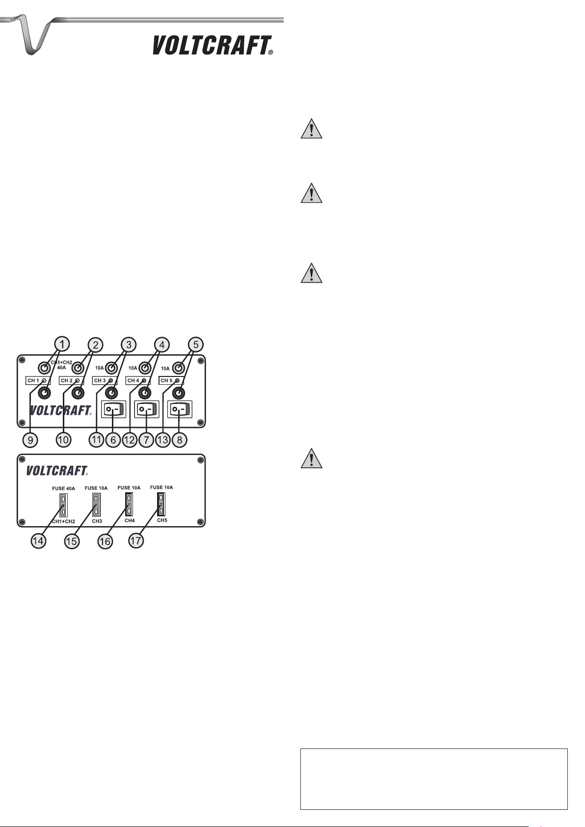
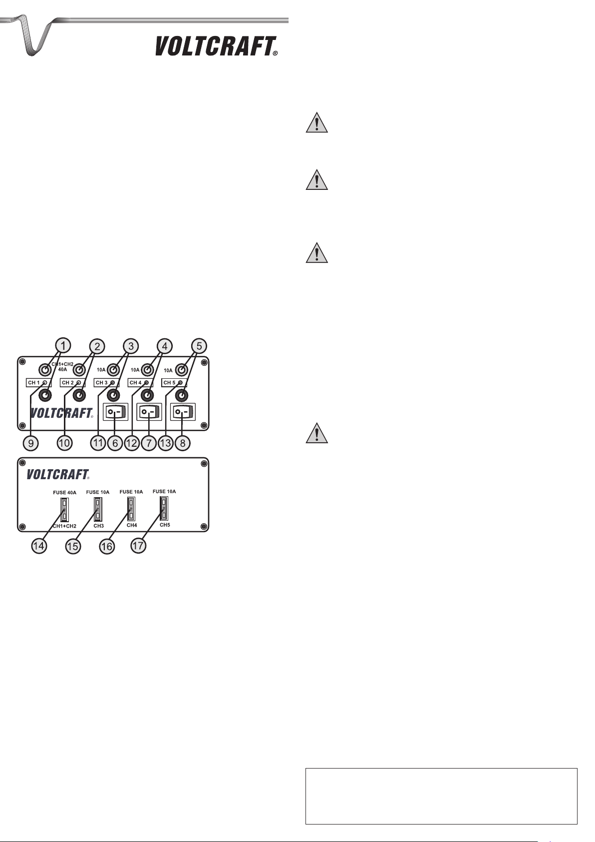
Geräteoberseite (Bild 1):
1 Anschlussbuchsen für Ausgang CH 1
2 Anschlussbuchsen für Ausgang CH 2
3 Anschlussbuchsen für Ausgang CH 3
4 Anschlussbuchsen für Ausgang CH 4
5 Anschlussbuchsen für Ausgang CH 5
6 Schalter für Ausgang CH 3
7 Schalter für Ausgang CH 4
8 Schalter für Ausgang CH 5
9 Kontroll-Anzeige Ausgang CH 1
10 Kontroll-Anzeige Ausgang CH 2
11 Kontroll-Anzeige Ausgang CH 3
12 Kontroll-Anzeige Ausgang CH 4
13 Kontroll-Anzeige Ausgang CH 5
Geräteunterseite (Bild 2):
14 Sicherung für Ausgang CH 1 und CH 2
15 Sicherung für Ausgang CH 3
16 Sicherung für Ausgang CH 4
17 Sicherung für Ausgang CH 5
Bild 1
Bild 2
SICHERUNGSWECHSEL
Die Ausgänge 1 und 2 (CH 1 und CH 2) sind gemeinsam mit einer 40 A Flach-Sicherung („FUSE
40 A“) abgesichert. Die Ausgänge 3, 4 und 5 (CH 3, CH 4 und CH 5) sind jeweils mit einer 10 A FlachSicherung („FUSE 10 A“) abgesichert. Sollte trotz korrekter Spannungsversorgung der Verteilerleiste
die LED an bestimmten Ausgängen nicht leuchten, so ist davon auszugehen, dass die dazugehörige
Sicherung durchgebrannt ist.
Um einen Sicherungswechsel durchzuführen gehen Sie wie folgt vor:
• Trennen Sie die Verteilerleiste von der Spannungsquelle (Netzteil/Fahrzeugakku).
• Trennen Sie die angeschlossenen Ladegeräte von der Verteilerleiste.
• Ziehen Sie mit einer geeigneten Spitzzange oder einer Pinzette die defekte Sicherung an der
Gehäuseunterseite (siehe Bild 2) heraus.
• Setzen Sie eine geeignete Ersatzsicherung mit gleicher Stromstärke in die Fassung ein.
• Prüfen Sie die korrekte Funktion der Verteilerleiste.
Wichtig!
Setzen Sie immer nur Ersatzsicherungen gleicher Stromstärke ein und verwenden Sie
niemals stärkere oder schwächere Sicherungen.
Eine defekte Sicherung darf niemals überbrückt werden! Es besteht Brand- und
Explosionsgefahr!
TECHNISCHE DATEN
Betriebsspannung ..................... 12 - 13,8 V/DC
Ausgangsströme ....................... CH 1 und CH 2 max. 40 A (Gesamt-Ausgangsstrom)
CH 3, CH 4 und CH 5 jeweils 10 A
Sicherungen .............................. 1 x 40 A, 3 x 10 A
Zuleitungslänge ........................ ca. 30 cm
Anschlussbuchsen .................... Bananenbuchsen 4 mm
Abmessungen ........................... 160 x 60 x 42 mm (L x B x H)
Gewicht ..................................... 248 g
PRODUKTBESCHREIBUNG
Der Anschluss der Verteilerleiste an ein geeignetes Netzteil oder an einen Fahrzeugakku erfolgt über
eine ca. 30 cm lange Zuleitung mit zwei 4 mm Bananensteckern.
Für den Anschluss von bis zu 5 Ladegeräten sind jeweils zwei 4 mm Bananenbuchsen (Rot = Plus/+
und Schwarz = Minus/-) vorgesehen.
Die Ausgänge CH 1 und CH 2 (siehe Bild 1, Pos. 1 und 2) sind dauerhaft mit der Zuleitung verbunden
und gemeinsam über eine 40 A Sicherung (siehe Bild 2, Pos. 14) abgesichert.
Die Ausgänge CH 3, CH 4 und CH 5 (siehe Bild 1, Pos. 3, 4 und 5) können über getrennte Schalter
(siehe Bild 1, Pos. 6, 7 und 8) ein- und ausgeschaltet werden und sind pro Ausgang mit einer 10 A
Sicherung (siehe Bild 2, Pos. 15, 16 und 17) abgesichert.
Die Spannungsversorgung der Ausgänge CH 1 und CH 2 wird jeweils mit einer grünen LED (siehe
Bild 1, Pos. 9 und 10) und an den schaltbaren Ausgängen CH 3, CH 4 und CH 5 mit einer orangen
LED (siehe Bild 1, Pos. 11, 12 und 13) angezeigt.
Impressum
Diese Bedienungsanleitung ist eine Publikation von Voltcraft®, Lindenweg 15, D-92242 Hirschau, Tel.-Nr. 0180/586 582 7
(www.voltcraft.de).
Alle Rechte einschließlich Übersetzung vorbehalten. Reproduktionen jeder Art, z. B. Fotokopie, Mikroverfilmung, oder die Erfassung in
elektronischen Datenverarbeitungsanlagen, bedürfen der schriftlichen Genehmigung des Herausgebers. Nachdruck, auch
auszugsweise, verboten.
Diese Bedienungsanleitung entspricht dem technischen Stand bei Drucklegung. Änderung in Technik und Ausstattung vorbehalten.
© Copyright 2011 by Voltcraft® V1_1111_01
Page 2
OPERATING INSTRUCTIONS
VERSION 11/11
5-FOLD DISTRIBUTOR STRIP
“POWER STRIP”
ITEM NO.: 23 76 82
INTENDED USE
The product enables concurrent power supply to up to five 12 V-chargers with a single mains adapter
or vehicle battery. The maximum permissible output currents at the distributor strip outputs must never
be exceeded.
Any use other than that described above will damage this product and involves the risk of short circuit,
fire, electric shock, etc!
The safety notes and all other information in these operating instructions always have to be observed.
This product complies with the statutory national and European requirements. All company names and
product names are trademarks of their respective owners. All rights reserved.
SCOPE OF DELIVERY
• Distributor strip
• Operating instructions
OPERATING ELEMENTS AND DISPLAYS
Figure 1
OPERATION
• Place the distributor strip on a stable, level and sufficiently large surface. Protect it from scratches
with a suitable cover.
• Connect the connection cable of the distributor strip to a suitable mains adapter (output voltage
12 V/DC).
Observe that the mains adapter must be sized sufficiently to supply all connected chargers with
¼
the required power.
Alternatively, a 12 V lead vehicle battery can be used for power supply instead of a mains adapter.
Observe good contact with the battery poles and prevent deep discharge of the vehicle battery!
Attention!
The vehicle battery must never be short-circuited. Danger of explosion!
• Connect the 12 V charger/s to the respective distributor strip outputs. Always observe correct
polarity of the connection sockets: Red = plus (+) and black = minus (-). If the charger you use has
no 4 mm banana plug, first apply a suitable plug to the charger connection cable.
Attention, important!
The distributor strip has no electronic protective circuits except for melt fuses. Therefore,
always avoid short circuits at the output sockets.
• If you operate the distributor strip with a mains adapter, switch it on now.
• Three of the five outputs of the distributor strip (CH 3, CH 4 or CH 5) can be switched on or off
individually by on/off switch if needed (see figure1, items 6, 7 and 8).
• Then operate your chargers according to the respective manufacturers’ instructions.
Attention!
Never pull a connection plug from the distributor strip while the connected charger is still
working under load.
Always terminate the charging or discharging process first.
FUSE REPLACEMENT
The outputs 1 and 2 (CH 1 and CH 2) are secured together with a 40 A flat fuse (“FUSE 40 A”). The
outputs 3, 4 and 5 (CH 3, CH 4 and CH 5) are secured with a 10 A flat fuse (“FUSE 10 A”) each. If the
LED of some outputs does not light up in spite of proper voltage supply to the distributor strip, it can be
assumed that the respective fuse has blown.
Replace the fuse as follows:
• Disconnect the distributor strip from the voltage source (mains adapter/vehicle battery).
• Disconnect the connected chargers from the distributor strip.
• Pull out the defective fuse at the bottom of the casing (see figure 2) with suitable tipped pliers or
tweezers.
• Insert a suitable fuse for the same current in the fitting.
• Check correct function of the distributor strip.
Important!
Only use spare fuses for the same current and never use any stronger or weaker fuses.
A defective fuse must never be bridged! There is a risk of fire and explosion!
Figure 2
Device top (figure 1):
1 Connection socket for output CH 1
2 Connection socket for output CH 2
3 Connection socket for output CH 3
4 Connection socket for output CH 4
5 Connection socket for output CH 5
6 Switch for output CH 3
7 Switch for output CH 4
8 Switch for output CH 5
9 Control indicator output CH 1
10 Control indicator output CH 2
11 Control indicator output CH 3
12 Control indicator output CH 4
13 Control indicator output CH 5
Device bottom (figure 2):
14 Fuse for output CH 1 and CH 2
15 Fuse for output CH 3
16 Fuse for output CH 4
17 Fuse for output CH 5
PRODUCT DESCRIPTION
The distributor strip is connected to a suitable mains adapter or vehicle battery via an approx. 30 cm
long supply line and two 4 mm banana plugs.
Two 4 mm banana sockets (red = plus/+ and black = minus/-) each are intended for connection of up
to 5 chargers.
The outputs CH 1 and CH 2 (see figure 1, items 1 and 2) are permanently connected to the supply line
and secured together via a 40 A fuse (see figure 2, item 14).
The outputs CH 3, CH 4 and CH 5 (see figure 1, items 3, 4 and 5) can be switched on and off by
separate switches (see figure 1, items 6, 7 and 8) and are secured with a 10 A fuse per output (see
figure 2, items 15, 16 and 17).
The voltage supply of outputs CH 1 and CH 2 are displayed with a green LED (see figure 1, items 9
and 10) and that of switchable outputs CH 3, CH 4 and CH 5 with an orange LED (see figure 1, items
11, 12 and 13) each.
TECHNICAL DATA
Operating voltage ..................... 12 - 13.8 V/DC
Output currents ......................... CH 1 and CH 2 max. 40 A (total output current)
CH 3, CH 4 and CH 5 each 10 A
Fuses ......................................... 1 x 40 A, 3 x 10 A
Supply line length ..................... approx. 30 cm
Connection sockets .................. banana sockets 4 mm
Dimensions ............................... 160 x 60 x 42 mm (L x W x H)
Weight ....................................... 248 g
Legal notice
These operating instructions are a publication by Voltcraft®, Lindenweg 15, D-92242 Hirschau/Germany, Phone +49 180/586 582 7
(www.voltcraft.de).
All rights including translation reserved. Reproduction by any method, e.g. photocopy, microfilming, or the capture in electronic data
processing systems require the prior written approval by the editor. Reprinting, also in part, is prohibited.
These operating instructions represent the technical status at the time of printing. Changes in technology and equipment reserved.
© Copyright 2011 by Voltcraft®.
Page 3

MODE D’EMPLOI
VERSION 11/11
BORNIER RÉPARTITEUR QUINTUPLE
« POWER STRIP »
N° DE COMMANDE : 23 76 82
UTILISATION CONFORME
Le produit permet une alimentation électrique simultanée de jusqu’à cinq chargeurs 12 V à l’aide d’un
seul bloc d’alimentation ou d’une seule batterie de véhicule. Ne jamais dépasser les courants de sortie
max. admissibles sur les sorties du bornier répartiteur.
Toute utilisation autre que celle susmentionnée peut endommager le produit et s’accompagner de
dangers tels que court-circuit, incendie, choc électrique, etc. !
Impérativement observer les consignes de sécurité ainsi que toutes les autres informations qui figurent
dans le présent mode d’emploi.
Ce produit est conforme aux exigences légales, nationales et européennes. Tous les noms
d’entreprises et appellations de produits contenus dans ce mode d’emploi sont des marques
déposées des propriétaires correspondants. Tous droits réservés.
CONTENU DE LA LIVRAISON
• Bornier répartiteur
• Mode d’emploi
ÉLÉMENTS DE COMMANDE ET AFFICHAGES
Figure 1
UTILISATION
• Installez le bornier répartiteur sur une surface stable, horizontale et suffisamment grande. Protégez
cette surface à l’aide d’une protection appropriée afin de ne pas la rayer.
• Branchez le câble de raccordement du bornier répartiteur sur un bloc d’alimentation approprié
(tension de sortie 12 V/CC).
Veillez alors à ce que le bloc d’alimentation dispose d’une puissance suffisante pour
¼
l’alimentation de tous les chargeurs raccordés avec le courant requis.
Vous pouvez sinon également employer une batterie au plomb 12 V à la place d’un bloc
d’alimentation pour l’alimentation électrique. Veillez alors à correctement raccorder les contacts aux
pôles de la batterie et évitez une décharge profonde de la batterie du véhicule !
Attention !
La batterie du véhicule ne doit jamais être court-circuitée. Danger d’explosion !
• Raccordez le ou les chargeurs 12 V aux sorties respectives du bornier répartiteur. Respectez alors
impérativement la polarité des prises femelles de raccordement : Rouge = plus (+) et noir =
moins (-). Si le chargeur que vous employez n’est pas muni de fiches banane 4 mm, vous devez
d’abord raccorder un connecteur approprié sur le câble de raccordement du chargeur.
Attention, important !
Le bornier répartiteur n’est pas équipé de circuits de protection en plus des fusibles. Évitez
donc impérativement tout court-circuit au niveau des prises femelles de sortie.
• Lorsque vous exploitez le bornier répartiteur avec un bloc d’alimentation, mettez maintenant ce
dernier sous tension.
• Trois des cinq sorties du bornier répartiteur (CH 3, CH 4 ou CH 5) peuvent, le cas échéant, être
activées ou désactivées séparément en actionnant l’interrupteur marche / arrêt correspondant (voir
figure 1, n° 6, 7 et 8.
• Utilisez ensuite vos chargeurs en observant les instructions du fabricant.
Attention !
Ne débranchez jamais les fiches de raccordement du bornier répartiteur tant que le
chargeur raccordé est sous charge.
Terminez toujours d’abord le cycle de charge ou de décharge.
REMPLACEMENT DES FUSIBLES
Les sorties 1 et 2 (CH 1 et CH 2) sont conjointement protégées par un fusible plat 40 A (« FUSE
40 A »). Les sorties 3, 4 et 5 (CH 3, CH 4 et CH 5) sont respectivement protégées par un fusible plat
10 A (« FUSE 10 A »). Si les DEL de certaines sorties ne sont pas allumées bien que l’alimentation
électrique ait correctement été établie, le fusible correspondant a probablement fondu.
Pour remplacer un fusible, procédez de la manière suivante :
• Débranchez le bornier répartiteur de la source de tension (bloc d’alimentation / batterie du véhicule).
• Débranchez les chargeurs raccordés au bornier répartiteur.
• À l’aide d’une pince pointue appropriée ou d’une pincette, retirez le fusible défectueux de la partie
inférieure du boîtier (voir figure 2).
• Insérez un fusible neuf approprié avec le même ampérage dans la douille du fusible.
• Assurez-vous du fonctionnement correct du bornier répartiteur.
Important !
Insérez toujours des fusibles neufs avec le même ampérage et n’employez jamais de
fusibles plus puissants ou plus faibles.
Ne jamais ponter un fusible défectueux ! Il y a danger d’incendie et d’explosion !
Figure 2
Face supérieure de l’appareil (figure 1) :
1 Prises femelles de raccordement pour la sortie CH 1
2 Prises femelles de raccordement pour la sortie CH 2
3 Prises femelles de raccordement pour la sortie CH 3
4 Prises femelles de raccordement pour la sortie CH 4
5 Prises femelles de raccordement pour la sortie CH 5
6 Interrupteur pour la sortie CH 3
7 Interrupteur pour la sortie CH 4
8 Interrupteur pour la sortie CH 5
9 Voyant de contrôle pour la sortie CH 1
10 Voyant de contrôle pour la sortie CH 2
11 Voyant de contrôle pour la sortie CH 3
12 Voyant de contrôle pour la sortie CH 4
13 Voyant de contrôle pour la sortie CH 5
Face inférieure de l’appareil (figure 2) :
14 Fusible pour les sorties CH 1 et CH 2
15 Fusible pour la sortie CH 3
16 Fusible pour la sortie CH 4
17 Fusible pour la sortie CH 5
DESCRIPTION DU PRODUIT
Le bornier répartiteur se branche sur un bloc d’alimentation approprié ou une batterie de véhicule à
l’aide d’un cordon d’alimentation d’env. 30 cm de long muni de deux fiches banane 4 mm.
Deux prises femelles banane 4 mm (rouge = plus / + et noir = moins / -) sont respectivement prévues
pour le branchement de jusqu’à 5 chargeurs.
Les sorties CH 1 et CH 2 (voir figure 1, n° 1 et 2) sont raccordés en permanence au cordon
d’alimentation et sont conjointement protégées par un fusible 40 A (voir figure 2, n° 14).
Les sorties CH 3, CH 4 et CH 5 (voir figure 1, n° 3, 4 et 5) peuvent être activées et désactivées à l’aide
d’interrupteurs distincts (voir figure 1, n° 6, 7 et 8) et chaque sortie est protégée par un fusible 10 A
(voir figure 2, n° 15, 16 et 17).
L’alimentation électrique des sorties CH 1 et CH 2 est respectivement affichée par une DEL verte (voir
figure 1, n° 9 et 10) et l’alimentation électrique des sorties commutables CH 3, CH 4 et CH 5 est
affichée par une DEL orange (voir figure 1, n° 11, 12 et 13).
CARACTÉRISTIQUES TECHNIQUES
Tension de service ................................ 12 - 13,8 V/CC
Courants de sortie ................................. CH 1 et CH 2 max. 40 A (courant de sortie total)
CH 3, CH 4 et CH 5 respectivement 10 A
Fusibles .................................................. 1 x 40 A, 3 x 10 A
Longueur du cordon d’alimentation ...... env. 30 cm
Prises femelles de raccordement ......... prises femelles banane 4 mm
Dimensions ............................................ 160 x 60 x 42 mm (L x l x h)
Poids....................................................... 248 g
Information légales
Ce mode d'emploi est une publication de la société Voltcraft®, Lindenweg 15, D-92242 Hirschau/Allemagne, Tél. +49 180/586 582 7
(www.voltcraft.de).
Tous droits réservés, y compris de traduction. Toute reproduction, quelle qu'elle soit (p. ex. photocopie, microfilm, saisie dans des
installations de traitement de données) nécessite une autorisation écrite de l'éditeur. Il est interdit de le réimprimer, même par extraits.
Ce mode d'emploi correspond au niveau technique du moment de la mise sous presse. Sous réserve de modifications techniques et de
l'équipement.
© Copyright 2011 by Voltcraft®.
Page 4

GEBRUIKSAANWIJZING
VERSIE 11/11
STEKKERDOOS MET 5 STEKKERS
“POWER STRIP”
BESTELNR.: 23 76 82
VOORGESCHREVEN GEBRUIK
Het product maakt het mogelijk om tot vijf 12 V-laadapparaten tegelijk van stroom te voorzien met
slechts een adapter of voertuigaccu. De maximum toegelaten uitgangsstromen aan de uitgangen van
de stekkerdoos mogen daarbij in geen geval worden overschreden.
Een andere toepassing dan hierboven beschreven, kan leiden tot beschadiging van het product.
Daarnaast bestaat het risico van bijv. kortsluiting, brand of elektrische schokken!
De veiligheidsinstructies en alle andere informatie in deze gebruiksaanwijzing dienen absoluut in acht
te worden genomen.
Dit product voldoet aan de voorwaarden van de nationale en Europese wetgeving. Alle vermelde
bedrijfs- en productnamen zijn handelsmerken van de respectievelijke eigenaren. Alle rechten
voorbehouden.
LEVERINGSOMVANG
• Stekkerdoos
• Gebruiksaanwijzing
BEDIENINGSELEMENTEN EN INDICATORLAMPJES
Afbeelding 1
BEDIENING
• Stel de stekkerdoos op op een stabiele, vlakke, voldoende grote oppervlakte. Bescherm de
stekkerdoos met een geschikte onderlegger tegen krassporen.
• Sluit de aansluitkabel van de stekkerdoos aan een geschikte adapter aan (uitgangsspanning
12 V/DC).
Let daarbij op dat de adapter voldoende sterk is om alle aangesloten laadapparaten van de
¼
nodige stroom te kunnen voorzien.
Als alternatief voor een adapter kan ook een 12 V-loodaccu van een voertuig als stroomtoevoer
worden gebruikt. Let daarbij op een goed contact aan de accupolen en vermijd een diepontlading
van de voertuigaccu!
Waarschuwing!
De voertuigaccu mag nooit worden kortgesloten. Explosiegevaar!
• Verbind het/de 12 V-laadapparaat/laadapparaten met de overeenkomstige uitgangen van de
stekkerdoos. Let op de juiste polariteit van de aansluitbussen: rood = plus (+); zwart = min (-). Als
het door u gebruikte laadapparaat geen banaanstekker van 4 mm heeft, moet eerst een geschikte
stekker aan de aansluitkabel van het laadapparaat worden aangebracht.
Opgelet! Belangrijk!
Naast de smeltzekering beschikt de stekkerdoos over geen elektronische
beschermingsschakelingen. Vermijd daarom in elk geval kortsluitingen aan de
uitgangsbussen.
• Wanneer u de stekkerdoos met behulp van een adapter gebruikt, schakelt u deze nu in.
• Drie van de vijf uitgangen van de stekkerdozen (CH 3, CH 4 of CH 5) kunnen indien nodig met
behulp van een in-/uitschakelaar (zie afbeelding 1, pos. 6, 7 en 8) afzonderlijk worden in- of
uitgeschakeld.
• Bedien aansluitend uw laadapparaat in overeenstemming met de voorschriften van de fabrikant.
Let op!
Trek de aansluitstekker nooit uit de stekkerdoos zolang het aangesloten laadapparaat nog
wordt belast.
Beëindig altijd eerst het laden of ontladen.
VERVANGEN VAN ZEKERINGEN
De uitgangen 1 en 2 (CH 1 en CH 2) zijn samen met een 40 A vlakzekering („FUSE 40 A“) beveiligd.
De uitgangen 3 en 4 (CH 3, CH 4 en CH 5) zijn samen met een 10 A vlakzekering („FUSE 10 A“)
beveiligd. Als de LED’s aan bepaalde uitgangen ondanks een correcte stroomtoevoer niet oplichten,
dan moet u aannemen dat de bijhorende zekering is doorgebrand.
Ga als volgt te werk om de zekeringen te vervangen:
• Ontkoppel de stekkerdoos van de spanningsbron (adapter/voertuigaccu).
• Ontkoppel de aangesloten laadapparaten van de stekkerdoos.
• Trek de defecte zekering met een geschikte scherpe tang of een pincet uit de onderkant van het
apparaat (zie afbeelding 2).
• Plaats een geschikte vervangzekering met dezelfde stroomsterkte in de fitting.
• Controleer de correcte werking van de stekkerdoos.
Belangrijk!
Plaats altijd uitsluitend vervangzekeringen met dezelfde stroomsterkte en gebruik nooit
sterkere of zwakkere zekeringen.
Een defecte zekering mag nooit worden overbrugd! Er bestaat brand- en explosiegevaar!
Afbeelding 2
Bovenkant apparaat (afbeelding 1):
1 Aansluitbussen voor uitgang CH 1
2 Aansluitbussen voor uitgang CH 2
3 Aansluitbussen voor uitgang CH 3
4 Aansluitbussen voor uitgang CH 4
5 Aansluitbussen voor uitgang CH 5
6 Schakelaar voor uitgang CH 3
7 Schakelaar voor uitgang CH 4
8 Schakelaar voor uitgang CH 5
9 Controlelampje uitgang CH 1
10 Controlelampje uitgang CH 2
11 Controlelampje uitgang CH 3
12 Controlelampje uitgang CH 4
13 Controlelampje uitgang CH 5
Onderkant apparaat (afbeelding 2):
14 Zekering voor uitgang CH 1 en CH 2
15 Zekering voor uitgang CH 3
16 Zekering voor uitgang CH 4
17 Zekering voor uitgang CH 5
PRODUCTBESCHRIJVING
De aansluiting van de stekkerdoos aan een geschikte adapter of aan een voertuigaccu gebeurt via
een ca. 30 cm lang snoer met twee banaanstekkers van 4 mm.
Voor de aansluiting van tot 5 laadapparaten zijn telkens twee 4 mm banaanbussen (rood = plus/+ en
zwart = min/-) voorzien.
De uitgangen CH 1 en CH 2 (zie afbeelding 1, pos. 1 en 2) zijn duurzaam met het snoer verbonden en
samen via een zekering van 40 A (zie afbeelding 2, pos. 14) beschermd.
De uitgangen CH 3, CH 4 en CH 5 (zie afbeelding 1, pos. 3, 4 en 5) kunnen via gescheiden
schakelaars (zie afbeelding 1, pos. 6, 7 en 8) worden in- en uitgeschakeld en zijn per uitgang met een
zekering van 10 A (zie afbeelding 2, pos. 15, 16 en 17) beveiligd.
De stroomtoevoer van de uitgangen CH 1 en CH 2 wordt telkens met een groene LED (zie afbeelding
1, pos.9 en 10) en aan de schakelbare uitgangen CH 3, CH 4 en CH 5 met een oranje LED (zie
afbeelding 1, pos. 11, 12 en 13) aangeduid.
TECHNISCHE GEGEVENS
Voedingsspanning .................... 12 - 13,8 V/DC
Uitgangsstromen ....................... CH 1 en CH 2 max. 40 A (totale uitgangsstroom)
CH 3, CH 4 en CH 5 telkens 10 A
Zekeringen ................................ 1 x 40 A, 3 x 10 A
Leidingslengte ........................... ca. 30 cm
Aansluitbussen ......................... banaanbussen 4 mm
Afmetingen ................................ 160 x 60 x 42 mm (L x B x H)
Gewicht ..................................... 248 g
Colofon
Deze gebruiksaanwijzing is een publicatie van de firma Voltcraft®, Lindenweg 15, D-92242 Hirschau/Duitsland, Tel. +49 180/586 582 7
(www.voltcraft.de).
Alle rechten, vertaling inbegrepen, voorbehouden. Reproducties van welke aard dan ook, bijvoorbeeld fotokopie, microverfilming of de
registratie in elektronische gegevensverwerkingsapparatuur, vereisen de schriftelijke toestemming van de uitgever. Nadruk, ook van
uittreksels, verboden.
Deze gebruiksaanwijzing voldoet aan de technische stand bij het in druk bezorgen. Wijziging van techniek en uitrusting voorbehouden.
© Copyright 2011 by Voltcraft®.
 Loading...