

Page 1
쮕
BEDIENUNGSANLEITUNG
°
Version 02/09
Digital Panelmeter PM 129
Best.-Nr. 10 69 42
Bestimmungsgemäße Verwendung
Das digitale Panelmeter ist zum Einbau in Geräte oder Gehäuse vorgesehen. Das Panelmeter
dient zur Messung und Anzeige von Gleichspannungswerten im Bereich von 0 - 200 mV (DC).
Durch individuelle, externe Beschaltungen können auch höhere Spannungen, sowie
Gleichströme etc. gemessen werden. Die Polaritätsanzeige erfolgt automatisch. Die LEDAnzeige umfasst 2000 Counts (Zeichen).
Das Modul darf nur bis zu einer Spannung von <75 VDC (über optionale
Spannungsteiler) offen betrieben werden. Ab einer Spannung von >/=75 V
müssen die entsprechenden Vorschriften bezüglich Luft- und Kriechstrecken
für den Berührungsschutz beachtet werden. Der Sicherheitsabstand zu
berührungsgefährlichen Spannungen/Leitern muss unbedingt beachtet und
eingehalten werden.
Das Panelmeter wird über 9V/DC (Blockbatterie etc.) versorgt.
Der Anschluss erfolgen auf der Anzeigenrückseite über Lötpunkte. Die Dezimalpunkte können
ebenfalls über Lötbrücken gesetzt werden.
Das Panelmeter ist zum Einbau in ein Gehäuse oder in andere Geräte vorgesehen. Der Betrieb
ist nur in trockenen Innenbereichen zulässig.
Das gesamte Produkt darf nicht geändert bzw. umgebaut werden! Die Sicherheitshinweise sind
unbedingt zu beachten!
Sicherheits- und Gefahrenhinweise
Lesen Sie bitte vor Inbetriebnahme die komplette Anleitung durch, sie enthält
wichtige Hinweise zum korrekten Betrieb.
Bei Schäden, die durch Nichtbeachten dieser Bedienungsanleitung verursacht werden, erlischt
die Garantie/Gewährleistung! Für Folgeschäden übernehmen wir keine Haftung!
Bei Sach- oder Personenschäden, die durch unsachgemäße Handhabung oder Nichtbeachten
der Sicherheitshinweise verursacht werden, übernehmen wir keine Haftung! In solchen Fällen
erlischt die Garantie/Gewährleistung.
Dieses Panelmeter ist kein Spielzeug und gehört nicht in Kinderhände.
Das Panelmeter ist CE-konform und erfüllt die erforderlichen europäischen Richtlinien.
Seien Sie besonders vorsichtig beim Umgang mit Lötkolben. Beachten Sie die Bedienungs-
anleitung. Erwärmen Sie die Lötstelle nur so lange wie nötig und so kurz wie möglich.
Berühren Sie keine Schaltungen oder Schaltungsteile, wenn darin höhere Spannungen als
25 V ACrms oder 35 V DC anliegen können! Lebensgefahr!
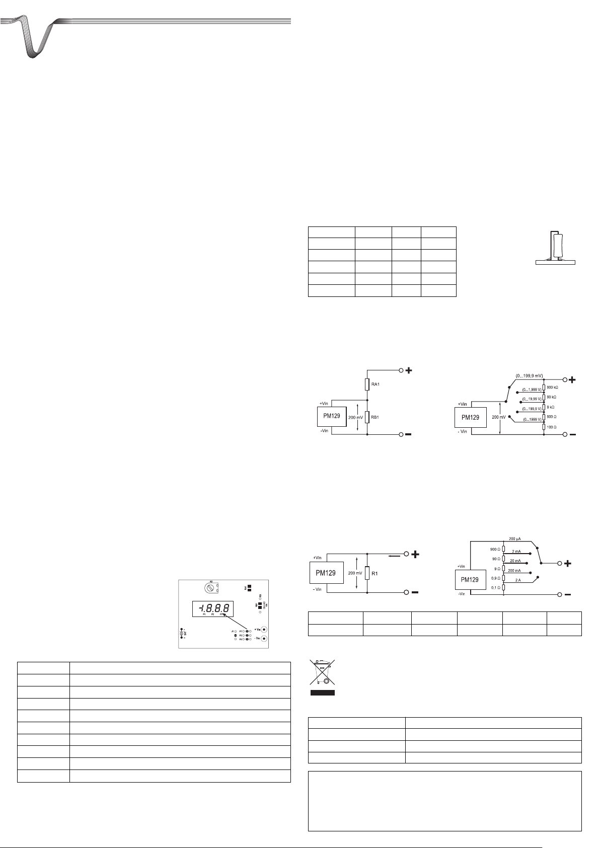
Montage
Bereiten Sie den Einbau-Ausschnitt vor. Der Abdeckrahmen ist für einen Ausschnitt von 67 x
29 mm (B x H) vorgesehen. Das Modul kann mit dem beiliegenden Rahmen von vorne befestigt
werden (max. Plattenstärke 7 mm). Das Befestigungsmaterial liegt bei.
Anschluss
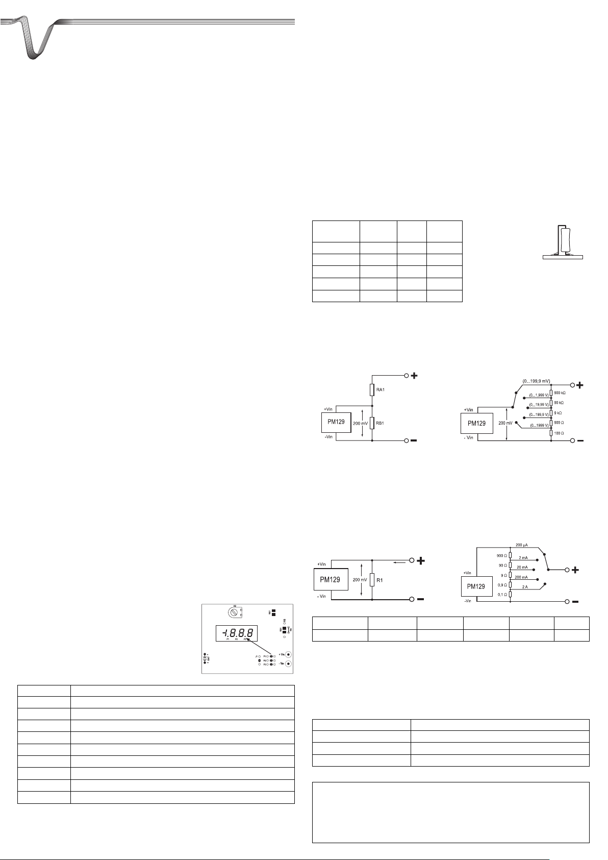
Auf der Rückseite erfolgen alle Anschlüsse und FunktionsLötbrücken.
Der Batterieclip ist bereits montiert und braucht nur noch ein
9V Block polungsrichtig angeschlossen werden.
Die entsprechenden Funktionen entnehmen Sie bitte der
folgenden Tabelle.
+ VIN Messeingang + (0 - 200 mV DC)
- VIN Messeingang – (Bezugspotential)
BAT Betriebsspannung 9VDC
P1 Lötbrücke für Dezimalpunkt 1,999
P2 Lötbrücke für Dezimalpunkt 19,99
P3 Lötbrücke für Dezimalpunkt 199,9
RA1 Widerstand für Spannungsteiler am Messeingang
RB1 Widerstand für Spannungsteiler am Messeingang
R2 Referenz-Abgleichpoti (Werksfunktion)
J3 Nur Werksfunktion, nicht Anwenderrelevant
Messeingang „+ VIN“ und „- VIN“
„+ VIN“ und „- VIN“ sind Differenzialeingänge. Sie reagieren auf die jeweils anliegende
Spannung und nicht auf die Spannung in Bezug zur Betriebsspannung. Als Messspannung darf
nur eine Gleichspannung angelegt werden.
Die Spannung am Messeingang darf im Lieferzustand ±200 mV nicht übersteigen, da das
Panelmeter sonst zerstört wird (Anzeige „I“ = Messbereichsüberschreitung).
Soll eine größere Spannung als ±200 mV gemessen werden, muss ein entsprechender
Spannungsteiler vorgeschaltet werden.
Spannungsversorgung „BAT“
Die Spannungsversorgung erfolgt über 9 V/DC und muss vom Messeingang galvanisch
getrennt sein. Ist die Anzeige bei Batteriebetrieb nur schlecht sichtbar, ist ein Batteriewechsel
nötig, um Fehlmessungen zu vermeiden.
Schaltungsbeispiele
Spannungs-Messbereiche wählen
Dieses Gerät kann für verschiedene Spannungsbereiche konfiguriert werden, indem
Widerstände an die Lötpunkte RA1 und RB1 gelötet werden.
Für den Grundmessbereich von 0 - 200 mV/DC ist bereits für RA ein 0 Ω Widerstand (Brücke)
eingebaut. RB wird nicht benötigt und bleibt offen.
Soll ein anderer Messbereich gewählt werden, unterbrechen Sie die Drahtbrücke RA und löten
an die freien Lötpunkte RA1 und RB1 die entsprechenden Widerstände ein. Die Werte können
Sie aus der Tabelle entnehmen. Die Spannungsteiler weisen eine Impedanz von 1 MΩ auf.
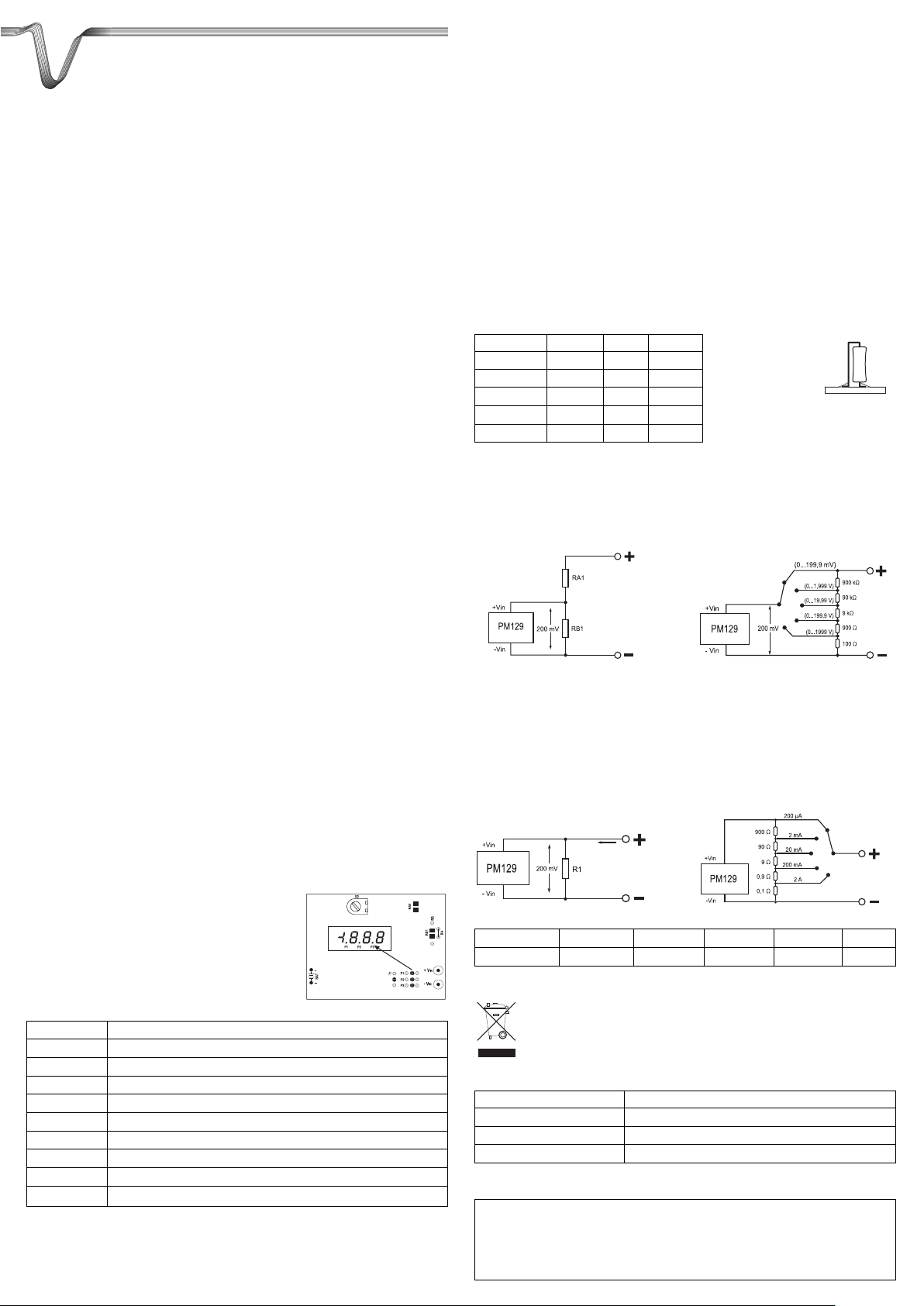
Messbereich RA1 RB1 Teiler
0 - 200 mV 0 Ω offen 1:1
0 - 2 V 900 kΩ 100 kΩ 10:1
0 - 20 V 990 kΩ 10 kΩ 100:1
0 - 200 V 999 kΩ 1 kΩ 1000:1
0 - 2000 V 999,9 kΩ 100 Ω 10000:1
☞
Passende Messwiderstände (0,1%) bzw. Präzisions-Spannungsteiler finden
Sie im Internet unter www.conrad.biz
Möchten Sie die Messbereiche umschaltbar machen, ist eine externe Beschaltung mit einem
Umschalter nötig. Die Drahtbrücke RA darf nicht aufgetrennt werden. Folgende Skizzen zeigen
die Umsetzung (Impedanz 1 MΩ):
Prinzip-Schaltbild Anschlussbild Spannungsdekade
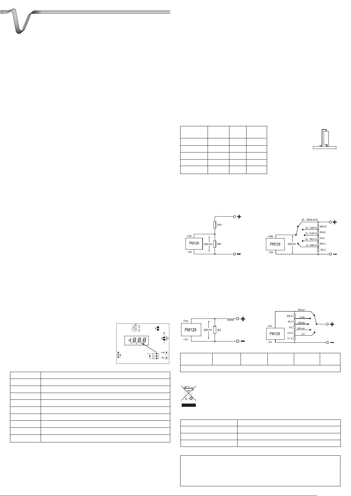
Strom-Messbereiche wählen
Mit einem einfachen Strom-Messwiderstand (Shunt) kann der Spannungsabfall an diesem
Widerstand gemessen werden. Die Stromstärke ist so indirekt messbar.
Soll ein einziger Messbereich gewählt werden, benötigen Sie nur einen Messwiderstand
(Shunt). Die Werte können Sie aus der Tabelle unten entnehmen. Die interne Drahtbrücke RA
darf nicht unterbrochen werden. Möchten Sie die Messbereiche umschaltbar machen, ist eine
externe Beschaltung (Dekade) mit einem Umschalter nötig. Die benötigten Widerstände sind in
der Skizze ersichtlich
Prinzip-Schaltbild Anschlussbild Stromdekade
Messbereich 0 - 200 µA 0 - 2 mA 0 - 20 mA 0 – 200 mA 0 – 2 A
R1 1 kΩ 100 Ω 10 Ω 1 Ω 0,1 Ω
Entsorgung
Elektronische Altgeräte sind Wertstoffe und gehören nicht in den Hausmüll. Ist das
Gerät am Ende seiner Lebensdauer, so entsorgen Sie das Gerät gemäß den
geltenden gesetzlichen Vorschriften bei Ihren kommunalen Sammelstellen. Eine
Entsorgung über den Hausmüll ist untersagt.
Technische Daten
Stromversorgung 9 V/DC, 50 mA
Grund-Messbereich 0 – 200 mV/DC (30 MΩ Impedanz, Messrate 3/s)
Genauigkeit ±(0,5 % + 1 digit)
Abmessungen (BxHxT) 68 x 44 x 21 mm
Impressum
Diese Bedienungsanleitung ist eine Publikation von Voltcraft®, Lindenweg 15, D-92242 Hirschau, Tel.-Nr. 0180/586 582 7 (www.voltcraft.de).
Alle Rechte einschließlich Übersetzung vorbehalten. Reproduktionen jeder Art, z.B. Fotokopie, Mikroverfilmung, oder die Erfassung in
elektronischen Datenverarbeitungsanlagen, bedürfen der schriftlichen Genehmigung des Herausgebers. Nachdruck, auch auszugsweise, verboten.
Diese Bedienungsanleitung entspricht dem technischen Stand bei Drucklegung. Änderung in Technik und Ausstattung vorbehalten.
© Copyright 2009 by Voltcraft
®
쮕
Biegen Sie die
Anschlüsse
entsprechend um
und löten diese wie
abgebildet auf die
Leiterplatte.
®
Page 2
OPERATING INSTRUCTIONS
°
Version 02/09
Digital Panel Meter PM 129
Item-No. 10 69 42
Intended use
The digital panel meter is intended for installation in other devices or casings. The panel meter
measures and displays direct currents in the range 0 to 200 mV (DC). Higher voltages, as well
as direct currents etc, can be measured by using single external circuits. The polarity is automatically displayed. The LED display contains 2000 counts (signals).
The module must not be operated openly at voltages greater than 75 VDC (by
an optional voltage divider). For voltages above 75 V, the appropriate instructions concerning the clearances to air and leakage paths for shock protection
must be followed. Always observe and adhere to the safe distance to dangerous contact voltages/wires.
The panel meter is powered by 9V/DC (battery etc.).
The device is connected via two soldering points on the rear. The decimal points can also be
set via soldering bridges.
The panel meter is intended to be installed in a casing or in other devices. The product is only
to be used in dry indoor locations.
No part of the product must be modified or rebuilt! Observe the safety instructions in their
entirety!
Safety Instructions and Hazard Warnings
Please read all of the operating instructions before using the product for the
first time; they contain important information about the correct operation.
The warranty will be void in the event of damage caused by failure to observe these safety
instructions! We do not assume any liability for any consequential damage!
We do not assume any liability for material and personal damage caused by improper use or
non-compliance with the safety instructions! The warranty will be void in such cases.
This panel meter is not a toy and should be kept out of the reach of children.
The panel meter has been CE tested and complies with the necessary European directives.
Please handle soldering irons with special care. Please follow these operating instructions.
Only heat the soldering point for as long as necessary and as short as possible.
Never touch circuits or parts of circuits with voltages greater than 25 V ACrms or 35 V DC!
Danger to life!
Installation
Prepare the Installation Section. The cover frame is designed for a 67 x 29 mm (W x H) section.
The module can be attached to the front using the supplied frame (max. panel thickness 7 mm).
Mounting material is included in the delivery.
Connection
All the connections and soldering bridges for the functions
are made on the back of the module.
The battery clip is already in place; only a 9V battery has to
be inserted, observe the correct polarity.
For the respective functions, please refer to the following
table:
+ VIN Measurement input + (0 - 200 mV DC)
- VIN Measurement input – (reference potential)
BAT Operating voltage 9VDC
P1 Soldering bridge for decimal point 1.999
P2 Soldering bridge for decimal point 19.99
P3 Soldering bridge for decimal point 199.9
RA1 Resistor for voltage divider at measuring input
RB1 Resistor for voltage divider at measuring input
R2 Reference adjustment potentiometer (factory function)
J3 Only factory function, not user-relevant
Measurement input “+ VIN” and “-VIN”
“+ VIN” and “-VIN” are differential inputs. They react to the voltage applied and not to the voltage relative to the operating voltage. Only a direct voltage may be applied as the measurement
voltage.
The voltage at the measurement input must not exceed ±200 mV in the delivery condition, otherwise the panel meter may be destroyed (display “I” = out of measurement range).
If voltages greater than ±200 mV are to be measured, an adequate voltage divider must to be
connected first.
Power Supply “BAT”
Power supply is 9 V/DC and must be galvanically isolated from the measurement input. If the
battery powered display is not readable, it is necessary to change the battery, in order to avoid
false measurements.
Circuit Examples
Choosing the voltage measurement range
This device can be configured for different voltage ranges, by soldering resistors in the positions RA1 and RB1.
For the basic measuring range from 0 - 200 mV/DC a 0Ωresistor (bridge) is already built in at
RA. RB is not used and remains free.
If another measurement range is chosen, disconnect the jumper RA and solder suitable resistors to the free soldering points RA1 and RB1. The relevant values can be found in the table.
The voltage divider has an impedance of 1MΩ.
Measurement RA1 RB1 Divider
range
0 - 200 mV 0 Ω free 1:1
0 - 2 V 900 kΩ 100 kΩ 10:1
0 - 20 V 990 kΩ 10 kΩ 100:1
0 - 200 V 999 kΩ 1 kΩ 1000:1
0 - 2000 V 999.9 kΩ 100 kΩ 10000:1
☞
Suitable measuring resistors (0.1%) and/or precision voltage dividers can be
found on the Internet at www.conrad.biz
If you want to make the measurement ranges selectable, an external connection to the divider
is necessary. The jumper RA must not be disconnected. The following sketches show the conversion (impedance 1 MΩ):
Principle Circuit Connection diagram voltage decade
Choosing the current measurement range
The potential drop across this resistor can be measured with an ordinary shunt. Thus, the current can be measured indirectly.
If only a single measurement range is chosen, you will only need one shunt. The appropriate
values can be found in the following table. The internal jumper RA must not be disconnected.
If you want to make the measurement ranges switchable, an external connection (decade) to a
divider is necessary. The resistors required can be seen from the sketch
Principle Circuit Connection diagram current decade
Measurement 0 - 200 µA 0 - 2 mA 0 - 20 mA 0 – 200 mA 0 – 2 A
range
R1 1 kΩ 100 Ω 10 Ω 1 Ω 0.1 Ω
Disposal
Electronic products are raw material and do not belong in the household waste. When
the device has reached the end of its service life, please dispose of it, according to the
current statutory requirements, at your local collecting site. Disposing of flat batteries
in the household waste is prohibited.
Technical Data
Power supply 9 V/DC, 50 mA
Basic measurement range 0 – 200 mV/DC (30 MΩ impedance, measuring rate 3/s)
Accuracy ±(0.5 % + 1 digit)
Dimensions (W x H x D) 68 x 44 x 21 mm
®
Impressum /legal notice in our operating instructions
These operating instructions are a publication by Voltcraft®, Lindenweg 15, D-92242 Hirschau/Germany, Phone +49 180/586 582 7 (www.voltcraft.de).
All rights including translation reserved. Reproduction by any method, e.g. photocopy, microfilming, or the capture in electronic data processing
systems require the prior written approval by the editor. Reprinting, also in part, is prohibited.
These operating instructions represent the technical status at the time of printing. Changes in technology and equipment reserved.
© Copyright 2009 by Voltcraft
®
®
Form the connection
as desired and solder
them to the circuit
board as shown.
Page 3
MODE D’EMPLOI
°
Version 02/09
Panneau de mesure numérique PM 129
N° de commande 10 69 42
Utilisation conforme
Le panneau de mesure numérique est prévu pour être monté dans un appareil ou dans un boîtier. Le panneau de mesure sert à la mesure et à l’affichage des valeurs de tension continue
comprises entre 0 et 200 mV (DC). À l’aide de raccordements individuels externes, il est possible de mesurer également des tensions plus élevées comme des courants continus, etc.
L’affichage de la polarité s’effectue automatiquement. L’affichage DEL comprend 2000 Counts
(signes).
Le module ne doit être utilisé que jusqu’à une tension de <75 VDC (au moyen
de diviseurs de tension, en option). A partir d’une tension de >/=75 V, il faut
respecter les prescriptions respectives concernant les lignes de fuite et les
distances d’isolement pour la protection contre les contacts. L’écart de sécurité entre le module et les tensions/conducteurs comportant des risques
d’électrocution doit absolument être respecté.
Le panneau de mesure est approvisionné de 9V/DC (pile, etc.).
Le raccordement se fait par des points de soudure au dos de l’’affichage. Les points des déci-
males peuvent également être définis par des straps.
Le panneau de mesure est prévu pour être monté dans un boîtier ou dans d’autres appareils.
l’appareil n’est à utiliser que dans des pièces dépourvues d’humidité et à l’intérieur.
L’ensemble de l’appareil ne doit être ni transformé, ni modifié. Respectez impérativement les
consignes de sécurité !
Consignes de sécurité et avertissements
Lisez intégralement les instructions d’utilisation avant la mise en service de
l’appareil, elles contiennent des consignes importantes pour son bon fonctionnement.
Tout dommage résultant d’un non-respect du présent mode d’emploi entraîne l’annulation de
la garantie! Nous déclinons toute responsabilité pour les dommages causés !
Nous déclinons toute responsabilité pour d’éventuels dommages matériels ou corporels dus à
un maniement incorrect ou à la non-observation des précautions d’emploi! Dans ces cas, la
garantie est annulée.
Ce panneau de mesure n’est pas un jouet et doit être maintenu hors de portée des enfants.
Le panneau de mesure est conforme à la norme CE et répond aux exigences des directives
européennes en vigueur.
Soyez particulièrement prudent en utilisant le fer à souder. Respecter les instructions d’-
utilisation. Chauffer le joint à souder qu’aussi longtemps que nécessaire et aussi brièvement
que possible.
Ne pas toucher les circuits ou les éléments de circuit, si des tensions supérieures à
25 V/CArms ou à 35 V/CC peuvent être appliquées ! Danger de mort !
Montage
Préparez le trou pour le montage. Le cadre est prévu pour une découpe de 67 x 29 mm (l x h).
Le module peut être fixé par l’avant avec le cadre fourni (épaisseur max. de plaque 7 mm). Le
matériel de fixation est joint.
Raccordement
Tous les raccordements et les ponts de soudure
fonctionnels s’effectuent à l’arrière du module.
Le clip de pile est déjà monté, il suffit d’insérer une pile 9 V
en respectant la polarité.
Les fonctions correspondantes sont indiquées dans le
tableau suivant.
+ VIN Entrée de mesure + (0 – 200 mV DC)
- VIN Entrée de mesure – (Potentiel de référence)
BAT Tension de service 9 VDC
P1 Strap pour point décimal 1,999
P2 Strap pour point décimal 19,99
P3 Strap pour point décimal 199,9
RA1 Résistance pour diviseur de tension à l’entrée de mesure
RB1 Résistance pour diviseur de tension à l’entrée de mesure
R2 Potentiomètre d’équilibrage de référence (fonction usine)
J3 Fonction usine, ne concerne pas l’utilisateur
Entrée de mesure “+ VIN” et “- VIN”
“+ VIN” et “- VIN” sont des entrées différentielles. Elles réagissent à chacune des tensions arrivantes et pas à la tension relative à la tension de service. Comme tension de mesure, vous ne
devez utiliser que la tension continue.
La tension au niveau de l’entrée de mesure ne doit pas dépasser ±200 mV à l’état de livraison ;
dans le cas contraire, le panneau de mesure est détruit (indication “I” = dépassement de la plage de mesure).
Pour la mesure d’une tension supérieure à ±200 mV, il convient de monter un diviseur de tension correspondant en amont.
Alimentation électrique “BAT”
L’alimentation électrique est assurée par 9 V/DC et doit être séparée électriquement de l’entrée
de mesure. Si, lors d’une alimentation avec des piles, l’affichage est difficile à voir, il faut remplacer les piles pour éviter des erreurs de mesure.
Exemples de branchement
Choisir des plages de mesure de tension
En soudant des résistances aux points de soudure RA1 et RB1, cet appareil peut être configuré pour différentes gammes de tension
Pour la plage de mesure de base comprise entre 0 - 200 mV/DC, il y a déjà une résistance de
0 Ω pour RA. RB n’est pas requis et reste ouvert.
Pour choisir une autre plage de mesure, interrompre le cavalier RA et souder les résistances
correspondantes sur les points RA1 et RB1. Les valeurs peuvent être prélevées dans le
tableau. Les diviseurs de tension ont une impédance de 1 MΩ.
Plage de RA1 RB1 Diviseur
mesure
0 - 200 mV 0 Ω ouvert 1:1
0 - 2 V 900 kΩ 100 kΩ 10:1
0 - 20 V 990 kΩ 10 kΩ 100:1
0 - 200 V 999 kΩ 1 kΩ 1000:1
0 - 2000 V 999,9 kΩ 100 Ω 10000:1
☞
Les résistances de mesure correspondantes (0,1 %) ou diviseurs de tension
de précision peuvent être trouvés sur le site www.conrad.biz
Si vous souhaitez des plages de mesures commutables, il faut prévoir le raccordement extérieur d’un commutateur. Le cavalier RA ne doit pas être coupé. Les croquis suivants montrent
la réalisation (impédance 1 MΩ):
Schéma de principe Schéma de raccordement décade de tensions
Choisir plages de mesure de courant
Une simple résistance de mesure du courant (Shunt) permet de mesurer la chute de tension
pour cette résistance. Cela permet de mesurer indirectement l’intensité du courant.
S’il faut choisir une seule plage de mesure, il suffit d’une seule résistance de mesure (Shunt).
Les valeurs peuvent être prélevées dans le tableau ci-dessous. Le fil de liaison RA interne ne
doit pas être interrompu. Si vous souhaitez des plages de mesures commutables, il faut prévoir
le raccordement extérieur (décade) avec un commutateur. Les résistances requises sont indiquées dans le schéma.
Schéma de principe Schéma de raccordement décade
Plage de mesure 0 - 200 µA 0 - 2 mA 0 - 20 mA 0 – 200 mA 0 – 2 A
R1 1 kΩ 100 Ω 10 Ω 1 Ω 0,1 Ω
Élimination
Les appareils électroniques usagés sont des matières recyclables qui ne doivent pas être jetées
dans les ordures ménagères ! Déposez l’appareil devenu inutilisable dans un centre communal
de tri de matériaux recyclables suivant les lois en vigueur. Il est interdit de le jeter dans les ordures
ménagères .
Caractéristiques techniques
Alimentation électrique 9 V/DC, 50 mA
Plage de mesure de base 0 – 200 mV/DC (30 MΩ impédance, taux de mesure 3/s)
Précision ± (0,5 % + 1 digit)
Dimensions (l x h x p) 68 x 44 x 21 mm
Informations /légales dans nos modes d'emploi
Ce mode d'emploi est une publication de la société Voltcraft®, Lindenweg 15, D-92242 Hirschau/Allemagne, Tél. +49 180/586 582 7
(www.voltcraft.de).
Tous droits réservés, y compris de traduction. Toute reproduction, quelle qu'elle soit (p. ex. photocopie, microfilm, saisie dans des installations de
traitement de données) nécessite une autorisation écrite de l'éditeur. Il est interdit de le réimprimer, même par extraits.
Ce mode d'emploi correspond au niveau technique du moment de la mise sous presse. Sous réserve de modifications techniques et de l'équipement.
© Copyright 2009 by Voltcraft
®
®
Plier des
raccordement au
besoin et souder sur
le circuit imprimé
comme le schéma
l’indique.
Page 4
GEBRUIKSAANWIJZING
°
Version 02/09
Digitale paneelmeter PM 129
Bestnr. 10 69 42
Beoogd gebruik
De digitale paneelmeter is geschikt voor de installatie in apparaten of behuizingen. Deze
paneelmeter is bestemd voor de meting en weergave van gelijkspanningen in een bereik van
0 tot 200 mV (DC). Door individuele, externe indelingen kunnen ook hogere spanningen zoals
gelijkstromen worden gemeten. De polariteitsaanduiding geschiedt automatisch. De LED-weergave omvat 2000 counts (tekens).
De module dient slechts tot een spanning van <75 VDC (via optionele spanningsdelers) in werking te worden gesteld. Vanaf een spanning van >/=75 V
moeten de bijbehorende voorschriften betreffende lucht- en kruipwegen voor
de contactbeveiliging in acht genomen te worden. U dient steeds de veiligheidsafstand ten opzichte van contactgevaarlijke spanningen en geleiders in
acht te nemen en op te volgen.
De paneelmeter wordt via 9 V/DC (blokbatterij enz.) gevoed.
De aansluiting vindt plaats via soldeerpunten op de achterkant van de weergave. De deci-
maalpunten kunnen tevens via soldeerbruggen worden geplaatst.
De paneelmeter is geschikt voor de installatie in een behuizing of in andere apparaten. Gebruik
het product alleen in droge binnenruimtes.
Het gehele product niet wijzigen resp. ombouwen! De veiligheidsinstructies dienen te allen tij-
de te worden opgevolgd!
Veiligheids- en gevaarinstructies
Lees alstublieft voor ingebruikname de volledige handleiding door. Deze
bevat belangrijke aanwijzingen omtrent het correcte gebruik.
Bij schade die wordt veroorzaakt door het niet in acht nemen van deze gebruiksaanwijzing, vervalt het recht op garantie! Voor gevolgschade aanvaarden wij geen enkele aansprakelijkheid!
Wij kunnen niet aansprakelijk worden gesteld voor materiële schade of persoonlijk letsel als
gevolg van ondeskundig gebruik of het niet in acht nemen van de veiligheidsvoorschriften! In
dergelijke gevallen vervalt de garantie.
Dit product is geen speelgoed en moet buiten het bereik van kinderen gehouden worden.
De paneelmeter is CE-conform en voldoet aan de noodzakelijke Europese richtlijnen.
Wees bijzonder voorzichtig bij het gebruik van soldeerbouten. Neem deze gebruiksaanwijzing
nauwkeurig in acht. Verwarm de soldeerplek zo kort mogelijk (niet langer dan nodig).
Raak schakelingen en schakeldelen niet aan als daarop een hogere spanning dan
25 V/wisselspanning rms of 35 V/ gelijksspanning kan staan! Levensgevaarlijk!
Montage
Bereid de opening voor de installatie voor. Het afdekframe is bestemd voor een uitsparing van
67 x 29 mm (b x h). De module kan met het meegeleverde frame aan de voorkant worden
bevestigd (max. plaatdikte 7 mm). Het bevestigingsmateriaal is meegeleverd.
Aansluiten
Alle aansluitingen en soldeerbruggen vinden aan de achterkant plaats.
De batterijclip is reeds gemonteerd en behoeft alleen
nog met de juiste polariteit op een 9 V-blok te worden aangesloten.
Zie de volgende tabel voor de bijbehorende functies.
+ VIN Meetingang + (0 - 200 mV DC)
- VIN Meetingang – (referentiepotentiaal)
BAT Bedrijfsspanning 9 VDC
P1 Soldeerbrug voor decimaalpunt 1,999
P2 Soldeerbrug voor decimaalpunt 19,99
P3 Soldeerbrug voor decimaalpunt 199,9
RA1 Weerstand voor spanningsdeler aan de meetingang
RB1 Weerstand voor spanningsdeler aan de meetingang
R2 Referentie-potentiometer (fabrieksfunctie)
J3 Alleen fabrieksfunctie, niet relevant voor gebruiker
Meetingang „+ VIN“ en „- VIN“
„+ VIN“ en „- VIN“ zijn differentiaalingangen. Deze reageren op de betreffede aanwezige spanning en niet op de spanning ten opzichte van de bedrijfsspanning. Als meetspanning dient
slechts gelijkspanning te worden aangesloten.
De spanning aan de meetingang dient in levertoestand niet boven ±200 mV te komen, omdat
de paneelmeter anders onherstelbaar wordt beschadigd (weergave „I“ = overschrijding meetbereik).
Indien een hogere spanning dan ±200 mV wordt gemeten dient een passende spanningsdeler
te worden voorgeschakeld.
Voedingsspanning „BAT“
De voedingsspanning geschiedt via 9 V/DC en dient galvanisch van de meetingang te zijn
gescheiden. Wanneer de weergave bij batterijwerking slecht zichtbaar is, dient de batterij te
worden vervangen om foutieve metingen te voorkomen.
Schakelvoorbeelden
Meetbereiken voor de spanning kiezen
Dit apparaat kan voor verschillende spanningsbereiken geconfigureerd worden als er weerstanden op de posities RA1 en RB1 gesoldeerd worden.
Voor het basismeetbereik van 0 - 200 mV/DC is reeds voor RA een 0 Ω weerstand (brug) ingebouwd. RB is niet nodig en blijft open.
Dient een ander meetbereik te worden gekozen, onderbreek dan de draadbrug RA en soldeer
aan de vrije soldeerplekken RA1 en RB1 de desbetreffende weerstanden. De waarden kunt u
uit de tabel ontnemen. De spanningsdelers tonen een impedantie van 1 MΩ .
Meetbereik RA1 RB1 Deler
0 - 200 mV 0 Ω open 1:1
0 - 2 V 900 kΩ 100 kΩ 10:1
0 - 20 V 990 kΩ 10 kΩ 100:1
0 - 200 V 999 kΩ 1 kΩ 1000:1
0 - 2000 V 999,9 kΩ 100 Ω 10000:1
☞
Geschikte meetweerstanden (0,1%) resp. precisie-spanningsdeler vindt u in
het internet onder www.conrad.biz
Indien u de meetbereiken omschakelbaar wilt maken is een externe indeling met een omschakelaar nodig. De draadbrug RA dient niet te worden losgemaakt. De volgende schetsen tonen
de omzetting (impedantie 1 MΩ):
Principe-bedradingsschema Aansluitschema spanningsdecade
Stroommeetbereiken kiezen
Met een eenvoudige stroommeetweerstand (shunt) kan de spanningsdaling op deze weerstand
worden gemeten. De stroomsterkte kan zo indirect worden gemeten.
Indien een enkel meetbereik dient te worden gekozen, heeft u slechts een meetweerstand
(shunt) nodig. De waarden kunt u uit de onderstaande tabel ontnemen. De interne draadbrug
RA dient niet te worden onderbroken. Indien u de meetbereiken omschakelbaar wilt maken is
een externe indeling (decade) met een omschakelaar nodig. De benodigde weerstanden worden in de schets getoond
Principe-bedradingsschema Aansluitschema stroomdecade
Meetbereik 0 - 200 µA 0 - 2 mA 0 - 20 mA 0 – 200 mA 0 – 2 A
R1 1 kΩ 100 Ω 10 Ω 1 Ω 0,1 Ω
Verwijdering
Oude elektronische apparaten kunnen gerecycled worden en horen niet thuis in het
huisvuil. Indien het apparaat het einde van zijn levensduur bereikt heeft, dient u het
volgens de geldende wettelijke voorschriften in te leveren bij een van de gemeentelijke inzamelpunten. Afvoer via het huisvuil is niet toegestaan.
Technische gegevens
Voedingsspanning 9 V/DC, 50 mA
Basismeetbereik 0 – 200 mV/DC (30 MΩ impedantie, leescapaciteit 3/s)
Nauwkeurigheid ±(0,5 % + 1 digit)
Afmetingen (bxhxd) 68 x 44 x 21 mm
Colofon in onze gebruiksaanwijzingen
Deze gebruiksaanwijzing is een publicatie van de firma Voltcraft®, Lindenweg 15, D-92242 Hirschau/Duitsland, Tel. +49 180/586 582 7
(www.voltcraft.de).
Alle rechten, vertaling inbegrepen, voorbehouden. Reproducties van welke aard dan ook, bijvoorbeeld fotokopie, microverfilming of de registratie in
elektronische gegevensverwerkingsapparatuur, vereisen de schriftelijke toestemming van de uitgever. Nadruk, ook van uittreksels, verboden.
Deze gebruiksaanwijzing voldoet aan de technische stand bij het in druk bezorgen. Wijziging van techniek en uitrusting voorbehouden.
© Copyright 2009 by Voltcraft
®
01_0209_01/HK
®
Buig de aansluitingen
dienovereenkomstig
om en soldeer deze
zoals afgebeeld op
de printplaat.
 Loading...