

Page 1
Impressum
Diese Bedienungsanleitung ist eine Publikation von Voltcraft®, Lindenweg 15, D-92242 Hirschau,
Tel.-Nr. 0180/586 582 7 (www.voltcraft.de).
Alle Rechte einschließlich Übersetzung vorbehalten. Reproduktionen jeder Art, z. B. Fotokopie, Mikroverfilmung, oder die
Erfassung in elektronischen Datenverarbeitungsanlagen, bedürfen der schriftlichen Genehmigung des Herausgebers.
Nachdruck, auch auszugsweise, verboten.
Diese Bedienungsanleitung entspricht dem technischen Stand bei Drucklegung. Änderung in Technik und Ausstattung
vorbehalten.
© Copyright 2009 by Voltcraft®.
Legal Notice
These operating instructions are a publication by Voltcraft®, Lindenweg 15, D-92242 Hirschau/Germany,
Phone +49 180/586 582 7 (www.voltcraft.de).
All rights including translation reserved. Reproduction by any method, e.g. photocopy, microfilming, or the capture in electronic
data processing systems require the prior written approval by the editor. Reprinting, also in part, is prohibited.
These operating instructions represent the technical status at the time of printing. Changes in technology and equipment
reserved.
© Copyright 2009 by Voltcraft®.
Information légales
Ce mode d'emploi est une publication de la société Voltcraft®, Lindenweg 15, D-92242 Hirschau/Allemagne,
Tél. +49 180/586 582 7 (www.voltcraft.de).
Tous droits réservés, y compris de traduction. Toute reproduction, quelle qu'elle soit (p. ex. photocopie, microfilm, saisie dans
des installations de traitement de données) nécessite une autorisation écrite de l'éditeur. Il est interdit de le réimprimer, même
par extraits.
Ce mode d'emploi correspond au niveau technique du moment de la mise sous presse. Sous réserve de modifications
techniques et de l'équipement.
© Copyright 2009 par Voltcraft®.
Colofon
Deze gebruiksaanwijzing is een publicatie van de firma Voltcraft®, Lindenweg 15, D-92242 Hirschau/Duitsland,
Tel. +49 180/586 582 7 (www.voltcraft.de).
Alle rechten, vertaling inbegrepen, voorbehouden. Reproducties van welke aard dan ook, bijvoorbeeld fotokopie,
microverfilming of de registratie in elektronische gegevensverwerkingsapparatuur, vereisen de schriftelijke toestemming van
de uitgever. Nadruk, ook van uittreksels, verboden.
Deze gebruiksaanwijzing voldoet aan de technische stand bij het in druk bezorgen. Wijziging van techniek en uitrusting
voorbehouden.
© Copyright 2009 by Voltcraft®.
01_0309_01
DIGITAL L-C-R MEASURING DEVICE „LCR-9063“
OPERATING INSTRUCTIONS PAGE 2 - 16
L-C-R-MÈTRE NUMÉRIQUE « LCR-9063 »
NOTICE D’EMPLOI PAGE 17 - 31
DIGITALES L-C-R-MESSGERÄT „LCR-9063“
BEDIENUNGSANLEITUNG SEITE 32 - 46
DIGITALE L-C-R-METER „LCR-9063“
GEBRUIKSAANWIJZING PAGINA 47 - 61
Best.-Nr. / Item No. /
N° de commande / Bestnr.:
12 26 12
VERSION 03/09
Page 2

3
Table of Contents
Page
1. Introduction . . . . . . . . . . . . . . . . . . . . . . . . . . . . . . . . . . . . .3
2. Notes on Safety . . . . . . . . . . . . . . . . . . . . . . . . . . . . . . . . . .3
3. Description of Operating Elements . . . . . . . . . . . . . . . . . . .6
4. Using the Measuring Device . . . . . . . . . . . . . . . . . . . . . . . .7
5. Making Measurements . . . . . . . . . . . . . . . . . . . . . . . . . . . . 8
6. Maintenance . . . . . . . . . . . . . . . . . . . . . . . . . . . . . . . . . . .13
7. Technical Data and Measurement Tolerances . . . . . . . . . .13
1. Introduction
The L-C-R measuring device enables you to make detailed measurements of no-load components, such as resistances in the
range 0 to 20 M Ω , capacitors in the range from a few pF up to
200 µF, and inductors in the range from a few µH up to 20 H.
Relatively low current consumption allows achievement of high
efficiency. The 13 mm high 3 1/2liquid crystal display (LCD) makes
the device very easy to read. The internally generated measurement frequency is approx. 250 Hz.
The measuring device can be used universally both in the hobby
and industrial (restricted) sectors, or in schools, etc..
2. Notes on Safety
• The measuring device is EMV safety-tested (domestic use)
and meets EG Guideline 89/336/EWG.
• The device has been manufactured and tested to DIN 57 411
Part 1/VDE 0411 Part 1, protective regulations for measuring
devices and leaves the factory in a technically safe condition.
To maintain this condition and ensure safe operation, the
2
Digital L-C-R-Measuring Device LCR-9063
Regulation use of the measuring device comprises:
• Measurement of unipolar or bipolar capacitors (C) of approx.
10 pF to 200 µF = 0.2 mF max.
• Measurement of resistances (R) up to 20 MΩ max.
• Measurement of inductance (L) up to 20 H max.
• Measurements in damp rooms or outside, or under adverse
environmental conditions are not permissible. Adverse environmental conditions are:
- damp or excessive humidity,
- dust or combustible gases, vapors or solvents,
- strong vibrations,
- strong magnetic fields, such as in the vicinity of machines
or loudspeakers,
- static electricity (fields and discharges).
- Uses other than specified are not permissible.
Important! Please read carefully!
Please read these operating instructions carefully. In case of
damage, ignoring the operating instructions revokes any possible claims under the guarantee and we can thus assume no liability for consequent damage.
GB
Page 3

5
• Ahead of measuring, check your measuring device and measuring leads for damage.
• Ahead of measuring, the capacitors being measured must be
fully discharged.
• Measurements of components or circuit components, etc.,
under loads are not permitted! Also, there is a potentially
lethal hazard if voltages greater than 25 VACrms or 35 VDC
are touched!
• Do not use the measuring device in rooms or in adverse environmental conditions in which combustible gases, vapors or
dust are present or may be present.
•
For your own safety, ensure that neither the measuring device
nor measuring leads become damp or wet.
• When measuring, only use the measuring leads supplied with
the measuring device. Only these leads are permitted.
• To avoid electric shocks, check that there is no contact (not
even indirectly) with measurement probes and the terminals/conductor rails (measurement points) during the measurements.
• If there are reasons for supposing that risk-free operation is
no longer possible, the unit must be deactivated and safetied
against accidental operation. Risk-free operation can no longer be supposed, when the equipment
- is visibly damaged,
- no longer functions
- has been stored long-term under adverse conditions
- has been exposed to stress during transport.
4
user must take account of the safety instructions and warnings contained in these operating instructions.
• Measuring devices should be kept away from children!
• In the workplace, the accident prevention measures of the
Association of Employer’s Liability Insurance for electrical
plant and operating material must be observed.
• In schools, training centers, hobby and self-help workshops,
working with measuring equipment and accessories must be
responsibly supervised by trained personnel.
• When opening panels or removing parts (except if this is
manually possible), live components may be exposed.
Connecting points may also be live. Ahead of any adjustment, maintenance, repair or exchange of parts or subassemblies during which the unit must be opened, connecting points must be disconnected from all voltage sources
and measurement circuits. If adjustment, maintenance or
repair must then proceed with the unit open, only trained
engineers, familiar with the risks and relevant regulations
(VDE 0100, VDE 0683, VDE 0701) are authorized to complete
the work.
• Capacitors in the unit may still be on-load, even when the
unit has been disconnected from all power sources and measuring circuits.
• Please take special care when handling voltages in excess of
25 V AC or 35 V DC voltage. Even at these voltages, contact
with electric cables can give a potentially lethal electrical
shock.
• Always remove the measurement probes before modifying
the measurement range.
Page 4

7
4. Use of the Multimeter
4.1 Fitting/Replacing the Battery
Your measuring device will only function correctly when fitted
with a 9-V block battery . If the LED „LOBAT“ lights up (battery voltage is less than 7.7 V), you must change the battery as follows:
Disconnect your measuring device from the measuring circuit,
remove the measuring leads from the measuring device, switch
off and use a suitable screwdriver to remove the screw attaching
the battery compartment cover. Carefully remove the cover.
Disconnect the used battery from the connecting terminal and
replace it with a new one of the same type (alkaline). After changing the battery, relocate the connected battery in the battery
compartment and carefully reclose the housing as described previously but in reverse order. When closing the battery compartment, check that the cables from the connecting terminals are
not jammed.
Important!
Never operate the measuring device when open. Potentially lethal hazard!
Remove used batteries from the measuring device, since even batteries protected against leakage can corrode and r elease chemicals
liable to damage health or damage the battery compartment.
4.2 Connecting the Measuring Leads
Never use other measuring leads than the ones supplied. Before
connection, check the condition of the connectors or crocodile
clips and that the insulation is not damaged.
6
• Never turn the equipment on immediately after transferring
it from a cold environment to a warm environment. Condensation can cause irreparable damage to your equipment.
Allow your device to acclimatize to the temperature of the
room before you switch it on.
3. Description of the Operating Elements
See fold-out for figure
1. 3 1/2digit LCD display, max. display value: 1999.
2. On/Off switch „0 - 1“.
3. Measurement range switch.
4. Slide switch „R - L/C“ for switching between resistance mea-
surement „R“, inductance measurement „L“ and capacitance measurement „C“.
5. Input sockets „+“ and „−“ for connecting measuring leads.
Important!
Please note the max. input parameters.
6. Battery compartment with cover (attached by screws).
Page 5

9
25 VAC. Take precautions in rooms in which dust, combustible
gases, vapors or fluids are or may be present. ==> Danger of
explosion!
Do not measure capacitors which are built into circuits or circuit
components.
3. Set the measurement function switch to the measurement
range desired.
4. Set the slide switch „R - L/C“ to „L/C“.
5. Connect the discharged capacitor to be measured to the cro-
codile clips of the measuring leads.
With unipolar capacitors (poled) check that polarity is cor-
rect. Do not extend the measuring leads supplied using
other extension leads as the lead capacitance thus arising
cannot be compensated when automatically setting to zero.
This can result in measurement errors.
Note(s)!
a) With capacitors either unlabeled are having labels no longer
readable, start the measurement using the lowest possible
measurement range and continue to adjust the measurement range switch until a sufficiently satisfactory display
(resolution) is obtained. Always remove the crocodile clips
from the measurement object before changing measurement ranges.
b) It is normal if a continuously changing value is displayed in
the smallest measurement range (2 nF) before the measurement is started. This is due to so-called stray capacitance in
the measuring leads, or the sensitive measurement input. At
very low capacitance values (e.g. 8.2 pF) the value displayed
(ahead of the measurement) must be deducted during the
measurement.
8
Important!
Avoid damage by never exceeding the max. input parameters.
4.3 Setting Up
When starting to measure, set the measuring device switch „0 - 1“
to „1“ and, after finishing your measurements to „0“ (this saves
wear on the battery). Measurement functions are color-coded: the
yellow range is for resistance measurement „R“, the blue range
for capacitance measurement „C“ and the violet range for inductance measurement „L“.
For switching between resistance measurement „R“ and capacitance „C“ or inductance measurement „L“, the slide switch must
be correctly set to „R - L/C“.
5. Making Measurements
5.1 Capacitance Measurements (C)
Measure capacitance as follows:
1. Connect the measuring leads supplied to the measuring
device: the red measuring lead to the „+“ socket (red) and
the black measuring lead to the „−“ socket (black) and
switch the measuring device switch „0 - 1“ to „1“.
2. Always discharge capacitors before connecting them to the
measuring device.
Important!
Connection of capacitors can produce high-energy discharges.
Take care! Potentially lethal hazard! Do not touch the connecting points of capacitors with voltages greater than 35 VDC or
Page 6

11
To obtain the highest possible resolution (and thus the smal-
lest possible error of measurement), the measurement
range must be adjusted to the expected inductance. If, for
example, a component label rating indicates a value of
6 mH (choke), the range „20 mH“ should be set.
Note(s)!
a)
With coils/inductance either unlabeled are having labels no
longer readable, start the measurement using the lowest possible measurement range and continue to adjust the measurement range switch until a sufficiently satisfactory display
(resolution) is obtained. Always remove the crocodile clips
from the measurement object before changing measurement
ranges.
b) It is normal if a continuously changing value is displayed in
the smallest measurement range (2 mH) before measurement is started. This is due to so-called stray capacitance in
the measuring leads, or the sensitive measurement input. At
very low „L“ values (e.g. 15 µH) the value displayed (ahead
of the measurement) must be deducted during the measurement.
c) For a broken coil, „1“ (for range overshoot) is displayed
instead of a measurement value.
d) It is not possible to measure the quality factor „Q“ of a
coil/inductance using this measuring device.
e) When measuring the inductance of resistances, misleading
values can be displayed.
After finishing with the measuring device, turn it off to save the
battery.
10
c) For a shorted capacitor, a value of „1“ (for range overshoot)
is displayed instead of a measurement value. For a capacitor
having a high leak current, either „1“ for overflow is displayed, or a value much higher than the rated value. The
value for a broken capacitor is displayed as „0....“ (or a very
few pF) in all ranges, except in the smallest range.
d) Especially with electrolytic capacitors a relatively great tole-
rance range is sometimes specified. This results in greater
values being measured with such types of capacitor than the
rated values. When displayed values are much lower than
rated values, the reason may be that the capacitor measured is faulty.
On completing measurements, switch the measuring device off
so as to save the battery.
5.2 Measurement of Inductance (coils) = (L)
You can use the measuring device LCR-9063 to test coils up to
20 H (= Henry = As/V) as follows:
1. Connect the measuring leads supplied to the measuring
device: the red measuring lead to the „+“ socket (red) and
the black measuring lead to the „−“ socket (black) and
switch the measuring device switch „0 - 1“ to „1“.
2. Set the measurement function switch to a range in the yellow sector („R“) and set the slide switch „R - L/C“ to „R“.
With open measuring cables and/or broken coils/windings, a
„1“ (for overflow) is displayed. Next, connect the measurement probes to the no-load measurement object (transformer coil, loudspeaker coil, relay coil, ignition coil, choke,
etc.).
Page 7

13
6. Maintenance
Changing the battery is described in Section 4.1. For cleaning the
device or the display window, use only a clean, dry, antistatic lintfree cleaning rag.
Important!
Never use cleaning agents containing carbon, petrol, alcohol or
similar since these will attack the surface finish of the measuring
device. Also, the vapors are a health and explosion hazard
7. Technical Data and Measurement Tolerances
7.1 Technical Data
Display . . . . . . . . . . . . . . . . .: 3-1/2-digit LCD up to 1999, with
automatic polarity indicator (with
electrolytic capacitors)
Max. measurement rate . . .: 2.5 measurements per second
Overflow display . . . . . . . . .: „1“ when range is exceeded
Environmental conditions
during the measurement . .:
0 °C to +50 °C, 0-80 % rel. humidi-
ty, non-condensing
in-store . . . . . . . . . . . . . . . .: −20 °C to +60 °C, 0-80 % rel. humi-
dity, after removal of the battery
from the measuring device
Temperature coefficient . . .: 0.5 ppm/°C in the range below
+18 °C and above +28 °C
Battery . . . . . . . . . . . . . . . . .: 9-V-block battery, alkaline, Code:
NEDA 1604 or JIS 006P or IEC 6F22
12
5.3 Measurement of Resistances (R)
Important!
Make absolutely sure that all circuits and circuit components, as
well as other measurement objects, are no-load.
Connect the measuring leads supplied to the measuring device:
the red measuring lead to the „+“ socket (red) and the black
measuring lead to the „−“ socket (black)). Set the measurement
function switch to a range in the yellow sector („R“) and set the
slide switch „R - L/C“ to „R“. With open measuring leads or highvalue/broken resistances „1“ (for overflow) is displayed. Next,
connect the measurement probes to the measurement object. To
maintain the highest possible resolution (and thus the smallest
possible error of measurement), the measurement range must be
adjusted to the expected resistance. If, for example, the color
code rating indicates a value of 120 Ω, the range „200 Ω „ should
be set.
Note!
When you are measuring resistance, check that the measurement
points you touch with the measuring probes when measuring are
free of dirt, oil, soldering material, or similar, which are likely to
result in errors in measurement values.
With resistances greater than approx. 2 MΩ it may occur that the
display needs a few moments to stabilize itself. If „1“ is displayed, you have exceeded the measurement range or the measurement section has been interrupted.
Page 8
15
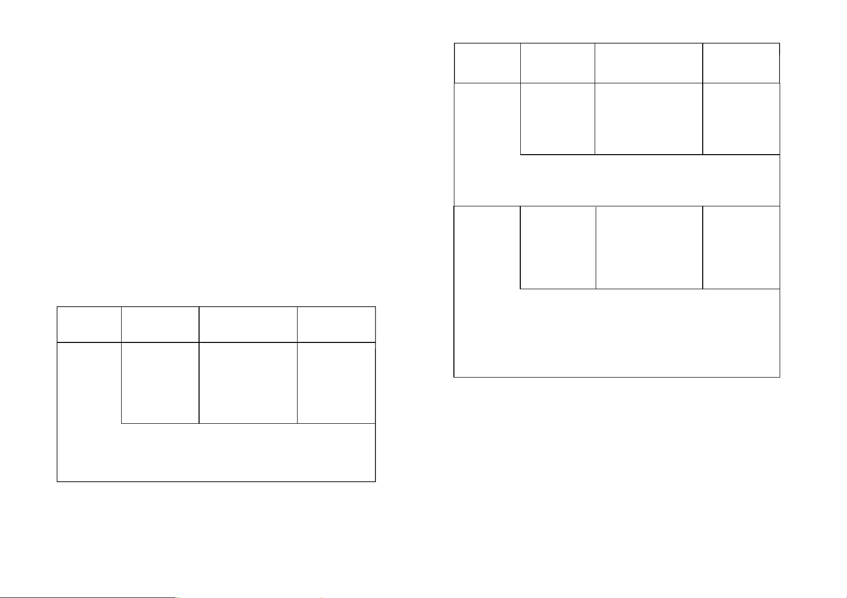
7.3 Max. Input Parameters
a) when measuring capacitance
Max. 2 nF in the 2 nF range
max. 20 nF in the 20 nF range
max. 200 nF in the 200 nF range
max. 2 µF in the 2 µF range
max. 20 µF in the 20 µF range
max. 200 µF in the 200 µF range
Resistance 200
2 k
20 k
200 k
2 M
20 M
Ω
Ω
Ω
Ω
Ω
Ω
0.1
1
10
100
1 k
10 k
Ω
Ω
Ω
Ω
Ω
Ω
±(2.0%+3dgts)
±(2.0%+3dgts)
±(2.0%+3dgts)
±(2.0%+3dgts)
±(2.0%+3dgts)
±(2.0%+3dgts)
In the range from approx. 2 Mohms to 20 Mohms, keep the
measuring cables as „short“ as possible to avoid instability
via external disturbance
Voltage at the open measuring lines:
- In the range from 200 Ω to 2 MΩ : 350 mV
- In the range from 20 MΩ : 180 mV
2 m H
20 m H
200mH
2 H
20 H
1 µH
10 µ H
100 µ H
1 m H
10 m H
±(3.0%+3dgts)
±(3.0%+3dgts)
±(3.0%+3dgts)
±(5.0%+5dgts)
±(5.0%+5dgts)
Leakage inductance with shorted measuring leads
in the 2 mH range: ≤ 30 µH
Test frequency: in all ranges approx. 250 Hz
Operating
Mode
Measurement
Range
Accuracy Resolution
Inductance
14
Current consumption . . . . .: approx. 5 mA for „R“ measure-
ments
approx. 9 mA for „C“ and „L“
measurements
Weight . . . . . . . . . . . . . . . . .: 185g (including 9 V battery)
Overall dimensions
(L X W X H) . . . . . . . . . . . . .: 120 x 72 x 37 mm (not incl. mea-
suring leads)
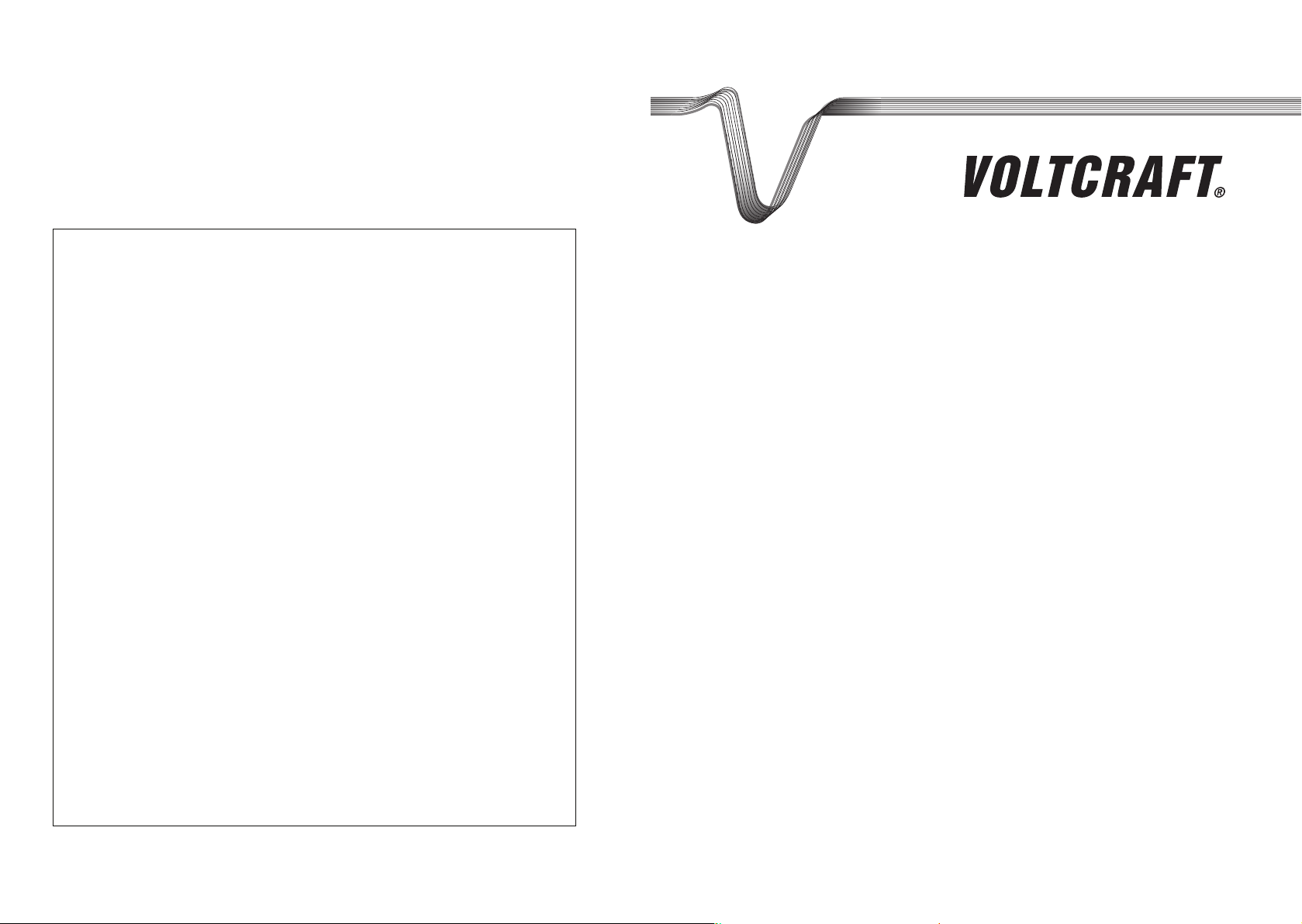
7.2 Measurement Tolerances
The measurement tolerances apply at a temperature of +23 °C ±5 °K,
at rel. humidity < 80 %, non-condensing.
Specification of accuracy in ± (% of read-off + number of digits
= dgt(s)
Capacitance
Operating
Mode
Test voltage: approx. 0.7 Vpeak-peak max.
Test frequency: in all range approx. 250 Hz
Setting to zero: automatic
Stray capacitance with open measuring leads in the 2 nF range: ≤ 30 pF
Measurement
Range
Accuracy Resolution
2 nF
20 nF
200 nF
2 µF
20 µF
200 µF
1 pF
10 pF
100 pF
1 nF
10 nF
100 nF
±(3.0%+3dgts)
±(3.0%+3dgts)
±(3.0%+3dgts)
±(3.0%+3dgts)
±(3.0%+3dgts)
±(3.0%+3dgts)
Page 9

17
L-C-R-mètre numérique LCR9063
Utilisation conforme de l’appareil de mesure :
• Mesure de condensateurs (C)(polarisés ou pas) de 10 pF environ à 200 µF = 0,2 mF
• Mesure de résistances jusqu’à 20 MΩ
• Mesure d’inductances (L) jusqu’à 20 H
• Il ne faut jamais utiliser l’appareil ni dans des locaux humides, ni en plein air, ni dans des circonstances défavorables.
Par circonstances défavorables, on entend :
- la présence d’humidité ou d’humidité atmosphérique
- la présence de poussières ou de substances explosives, de
solvants
- la présence de vibrations
- la présence de champs magnétiques, comme par exemple
à proximité de machines ou de haut-parleurs,
- la présence d’électricité statique (champs et décharges)
• Toute autre utilisation est interdite.
Important ! À lire impérativement !
Lisez attentivement cette notice. Vous ne pouvez plus bénéfi cier
de la garantie si vous endommagez l’appareil faute d’avoir lu et
respecté les instructions de cette notice. Les dommages qui en
résulteraient n’engagent en aucune manière notre responsabilité.
F
16
Important!
There is no protection against irreparable damage by capacitors
under load. Please therefore strictly observe safety regulations.
b) when measuring inductance
Max. 2 mH in the 2 mH range
max. 20 mH in the 20 mH range
max. 200 mH in the 200 mH range
max. 2 H in the 2 H range
max. 20 H in the 20 H range
c) when measuring resistance
Max. 200 Ω in the 200 Ω range
max. 2 K Ω in the 2 KΩ range
max. 20 K Ω in the 20 KΩ range
max. 200 K Ω in the 200 KΩ range
max. 2M Ω in the 2MΩ range
max. 20M Ω in the 20MΩ range
Important!
There is no protection against too high an input voltage. Make
sure that you only measure no-load elements and sections.
Page 10

19
• L’appareil de mesure, construit en conformité avec la norme
de protection de l’appareillage électronique DIN57411 1ère
partie VDE0411 1ère partie, a quitté nos ateliers en parfait
état de fonctionnement. Pour ne pas compromettre cet état
et garantir la sécurité de l’utilisateur, celui-ci doit respecter
impérativement les consignes de sécurité et tenir compte des
mises en garde, telles qu’elles figurent dans cette notice.
• Tenir hors de portée des enfants !
•
Dans le cadre d’activités à caractère commercial, l’usage de
l’appareil de mesure ne peut se faire qu’en conformité avec
la réglementation professionnelle en vigueur pour l’outillage
et les installations électriques des corps de métiers concernés.
• Dans les écoles, les centres de formation, les ateliers de bricolage, l’utilisation des appareils de mesure et de leurs accessoires doit être supervisée par du personnel qualifié.
•
Par l’ouverture de certaines parties ou leur suppression, sauf
lorsque cette manipulation est possible à main nue sans outil,
l’accès peut être donné à des parties soumises à des différences de potentiels dangereuses. Il peut également régner une
tension sur certaines bornes de connexion. Avant toute intervention nécessitant l’ouverture de l’appareil, toute réparation
ou remplacement de pièces isolées ou d’ensembles
, il faut
impérativement débrancher l’appareil des circuits électriques.
Si, pour l’entretien ou la réparation de l’appareil, il est nécessaire de le faire fonctionner sous tension, cette intervention
ne doit être effectuée que par du PERSONNEL QUALIFIÉ,
informé des risques encourus et respectueux des règles de
sécurité (VDE-0100, VDE-0683, VDE-0701).
• Il est possible que les condensateurs de l’appareil restent
chargés même une fois que l’appareil a été déconnecté des
sources de tension et des circuits de mesure.
18
Table des matières
page
1. Présentation . . . . . . . . . . . . . . . . . . . . . . . . . . . . . . . . . . . .18
2. Consignes de sécurité . . . . . . . . . . . . . . . . . . . . . . . . . . . .18
3. Description des organes de commande . . . . . . . . . . . . . . .21
4. Utilisation de l’appareil de mesure . . . . . . . . . . . . . . . . . . 22
5. Comment effectuer les mesures ? . . . . . . . . . . . . . . . . . . .23
6. Entretien . . . . . . . . . . . . . . . . . . . . . . . . . . . . . . . . . . . . . .28
7. Caractéristiques techniques et tolérances . . . . . . . . . . . . .28
1. Présentation
Cet appareil qui est à la fois un capacimètre, un inductancemètre
et un ohmmètre, vous permet de faire toutes sortes de mesures
sur des composants hors tension : sur des résistances de 0 à 20 MΩ,
des condensateurs depuis quelques pF jusqu’à 200 µF et enfin des
bobines de quelques µH à 20 H. La consommation relativement
faible de l’appareil lui confère une grande efficacité.
Le résultat
des mesures est indiqué clairement sur l’afficheur à cristaux liquides par trois chiffres et demi de 13 mm de hauteur. La fréquence
de mesure de 250 Hz environ est produite par un générateur
interne.
L’appareil de mesure numérique est d’usage universel, aussi bien
pour le bricolage que pour des applications industrielles (sous
certaines conditions) ou scolaires.
2. Consignes de sécurité
• L’appareil de mesure est conforme aux normes de compatibilité électromagnétique et aux normes de sécurité pour les
applications domestiques (recommandations européennes
89/336/EWG).
Page 11

21
- quand l’appareil est visiblement endommagé,
- quand l’appareil ne fonctionne plus et
- quand l’appareil a été stocké longtemps dans de mauvaises conditions,
et enfin
- quand l’appareil a subi de mauvaises conditions de transport.
• Ne mettez jamais l’appareil sous tension lorsqu’il vient d’être
soumis à un changement de température important, par
exemple immédiatement après le passage d’un local non
chauffé à un local chauffé. La condensation qui en résulterait
pourrait, dans certaines conditions, provoquer la destruction
de l’appareil. Laissez l’appareil hors service pour qu’il prenne
progressivement la température ambiante.
3. Organes de commande
Voir l’illustration sur la page dépliante
1. Afficheur à cristaux liquides à 3 chiffres et demi. Valeur
maximale affichée : 1999.
2. Interrupteur marche-arrêt.
3. Sélecteur de calibre.
4. Commutateur R - L/C pour passer du mode ohmmètre „R“
aux modes inductancemètre „L“ et capacimètre „C“.
5. Bornes de „+“ et „−“ de connexion des cordons de mesure.
Attention !
Ne dépassez en aucun cas les valeurs limites des grandeurs d’entrée.
6. Compartiment de la pile à couvercle vissé.
20
• Il faut prendre les précautions d’usage en présence de tensions alternatives supérieures à 25 V (ca) ou de tensions continues de plus de 35 V (cc). Ce sont des valeurs suffisantes
pour causer un choc électrique en cas de contact avec des
parties conductrices.
• Avant de procéder à un changement de calibre, il faut
déconnecter les cordons et les sondes de mesure du circuit à
mesurer.
• Avant de procéder à quelque mesure que ce soit, vérifier le
bon état de l’appareil, des cordons ainsi que des sondes de
mesure.
• Avant de procéder à quelque mesure que ce soit, il faut
décharger entièrement les capacités (les condensateurs) à
mesurer.
• Il ne faut jamais procéder à des mesures sur des composants
sous tension. Tout contact avec des tensions supérieures à
25 Vcaeff ou 35 Vcc constitue un danger de mort.
• N’utilisez pas cet appareil dans de mauvaises conditions ou
dans des locaux où pourraient se trouver des gaz ou des
poussières inflammables.
•
Pour votre propre sécurité, ni l’appareil ni ses cordons de
mesure ne doivent jamais être ni humides ni a fortiori mouillés.
• Il ne faut utiliser que les cordons de mesure d’origine.
• Pour éviter tout risque de choc électrique, il faudra empêcher
tout contact direct ou indirect autant avec les sondes de
mesure qu’avec les points de mesure (bornes, connexions).
• Aussitôt qu’il apparaît que l’appareil ne peut plus être utilisé
sans danger, il convient de le mettre hors service ainsi que de
prendre toutes les mesures adéquates pour empêcher sa
remise en service accidentelle. Il faut considérer que les conditions normales d’utilisation ne sont plus réunies
Page 12

23
Attention !
Ne dépassez en aucun cas les valeurs limites des grandeurs
d’entrée.
4.3 Mise en service
Pour mesurer, mettez l’appareil en service en mettant l’inverseur
„0 - 1“ en position „1“. À la fin de la mesure, vous mettrez cet
inverseur en position „0“ afin de ne pas user la pile inutilement.
Les fonctions de mesure ont chacune une couleur différent. Pour
la mesure de résistance R, c’est le jaune, pour la mesure de capacité C, c’est le bleu, et enfin le violet pour la mesure d’inductance
L. Pour activer le mode de mesure souhaité, il faut mettre le
sélecteur R-L/C dans la position correspondante.
5. Mesurer
5.1 Mesure de capacité (C)
Voici comment procéder à la mesure de capacité :
1. Reliez les cordons de mesure fournis avec l’appareil : le cordon rouge à la borne „+“ (rouge) et le cordon noir à la
borne „−“ (noire). Mettez l’inverseur „0-1“ en position „1“
pour mettre l’appareil en service.
2. Prenez soin de toujours décharger le condensateur avant de
relier à l’appareil de mesure.
Attention !
Lorsque l’on court-circuite les broches d’un condensateur pour le
décharger, l’énergie libérée n’est pas une grandeur négligeable.
Danger de mort ! Ne touchez jamais les broches d’un condensa-
22
4. Utilisation de l’appareil de mesure
4.1 Mise en place de la pile - remplacement de la pile
Pour que votre appareil de mesure fonctionne correctement, il
doit être muni d’une pile de 9 V. Quand le symbole de remplacement de la pile „LOBAT“ apparaît sur l’afficheur (la tension de la
pile est alors tombée à 7,7 V), il faut remplacer la pile. Pour cela
vous procéderez de la façon suivante :
Supprimez toute connexion entre le multimètre et le circuit de
mesure, retirez les cordons de mesure de l’appareil puis dévissez,
à l’aide d’un tournevis adéquat, la vis de fixation du couvercle du
compartiment de la pile. Otez ce couvercle avec précaution,
déconnectez la pile usée et remplacez-la par une pile neuve du
même type (alcaline).
Une fois le changement de pile effectué, introduisez la nouvelle
pile dans le compartiment de la pile que vous refermerez soigneusement. Prenez soin de ne pas coincer les fils de la pile entre
le couvercle et le boîtier.
Attention !
Ne mettez jamais l’appareil de mesure en service quand il est
ouvert ! Danger de mort !
Ne laissez pas de pile usagée dans l’appareil de mesure, car
même les piles étanches risquent de se corroder et laisser échapper des substances chimiques qui seraient nocives pour votre
santé et risquent d’endommager votre multimètre.
4.2 Mise en place des cordons de mesure
N’utilisez pour vos mesures que les cordons d’origine. Avant
d’établir une nouvelle connexion, vérifiez toujours soigneusement l’état de l’isolant des fiches et des pinces crocodiles.
Page 13

25
c) Si un condensateur est en court-circuit, l’afficheur donne un
„1“ pour signaler le dépassement de capacité. Si le condensateur mesuré présente un courant de fuite d’intensité élevée, l’appareil indique, pour signaler le dépassement, soit
„1“ soit une valeur beaucoup plus élevée que celle qui est
indiquée sur le composant. Si le condensateur présente ‘une
interruption de circuit“, l’appareil affiche „0“ dans tous les
calibres, ou éventuellement une très faible valeur (quelques pF) dans le calibre le plus petit.
d) La tolérance des condensateurs électrolytiques est assez
forte. Il n’est donc pas rare que l’on mesure sur un condensateur électrolytique une valeur réelle plus élevée que celle
de la capacité annoncée par le fabricant. Si la capacité
affichée est beaucoup plus faible que celle qui est indiquée
sur le composant, il est possible aussi que le composant soit
défectueux.
Une fois les mesures achevées, coupez l’appareil afin de ménager
la pile.
5.2 Mesure d’inductance (bobines = L)
Cet appareil de mesure (LCR-9063) permet de mesurer des bobines jusqu’à 20 H (H = Henry = As/V). Procédez comme suit :
1. Reliez les cordons de mesure fournis avec l’appareil : le cordon rouge à la borne „+“ (rouge) et le cordon noir à la
borne „−“ (noire). Mettez l’inverseur „0 - 1“ en position „1“
pour mettre l’appareil en service.
2. Mettez le sélecteur sur l’un des calibres jaunes R et mettez
l’inverseur „R - L/C“ en position „R“. Si le circuit est ouvert,
l’afficheur indique „1“ pour signaler le dépassement de
capacité. Puis reliez les pointes des cordons de mesure à
24
teur soumis à des tensions supérieures à 35 Vcc ou 25 Vca.
Prenez les précautions qui s’imposent en présence de poussières, de vapeurs, de liquides ou de gaz inflammables afin d’éviter
tout risque d’explosion.
Ne faites pas de mesures sur des condensateurs montés dans un
circuit.
3. Réglez le sélecteur de fonction de mesure sur le calibre
approprié.
4. Mettez l’inverseur „R - L/C“ en position „L/C“.
5. Reliez le condensateur à mesurer, déchargé et hors potentiel
avec les pinces crocodiles des cordons de mesure.
Les condensateurs polarisés doivent être connectés dans le
bon sens. Ne rallongez pas les cordons de mesure. Les capacités parasites qui en résulteraient fausseraient les mesures
car le tarage automatique ne fonctionne plus.
Remarques :
a)
Pour les condensateurs ne portant aucune inscription (ou
ceux dont l’inscription est illisible), commencez par le calibre
le plus faible que vous augmentez au fur et à mesure jusqu’à
ce que vous obteniez une indication satisfaisante. Il est
recommandé de débrancher les pinces crocodiles à chaque
changement de calibre.
b)
Il n’est pas anormal qu’avant de commencer à mesurer dans
le calibre le plus faible (2 nF), l’affichage soit instable. Il s’agit
de l’effet de capacités parasites dans les cordons de mesure
ou de la grande sensibilité d’entrée. Il conviendra de soustraire la valeur affichée avant la mesure de la valeur affichée
pendant la mesure, notamment de faibles capacités (comme
par exemple 8,2 pF).
Page 14

27
5.3 Mesure de résistance (R)
Attention !
Vérifiez que tous les circuits et les composants sur lesquels vous
effectuez des mesures sont rigoureusement HORS POTENTIEL.
Reliez les cordons de mesure fournis avec l’appareil : le cordon
rouge à la borne „+“ (rouge) et le cordon noir à la borne „−“
(noire). Mettez l’inverseur „R - L/C“ en position „R“ et le commutateur sur une plage de mesure jaune (R). Quand les sondes
de mesure sont en l’air, l’afficheur indique ‘1’. Une fois que vous
aurez connecté les sondes de mesure au circuit. Réglez le sélecteur de fonction de mesure sur le calibre approprié par rapport
à la valeur de résistance supposée. Si par exemple les anneaux de
couleur indiquent que la résistance est de 120 Ω, il est préconisé
de choisir le calibre 200 Ω.
Remarque
Les pointes de mesure utilisées pour la mesure de résistance doivent être propres, exemptes de graisse ou de toute autre substance susceptible de fausser les mesures.
Pour les résistances de plus de 2 MΩ, il faut quelques fractions de
secondes avant que l’appareil stabilise la valeur affichée. Si l’afficheur indique ‘1’, c’est que le calibre est dépassé ou encore que
le circuit est interrompu.
Une fois les mesures achevées, coupez l’appareil afin de ménager
la pile.
26
l’objet à mesurer, hors potentiel. Il peut s’agit de l’enroulement d’un transformateur, de la bobine d’un H.-P., de la
bobine d’un relais, d’une bobine d’amorçage, d’une self de
choc, etc.
Pour obtenir la meilleure résolution possible, il faut choisir le
calibre correspondant à l’inductance supposée du composant. Si par exemple un composant est donné pour 6 mH (self
de choc), il convient de choisir d’emblée le calibre 200 mH.
Remarques :
a) Pour les inductances ne portant aucune inscription (ou celles
dont l’inscription est illisible), commencez par le calibre le
plus faible que vous augmentez au fur et à mesure jusqu’à
ce que vous obteniez une indication satisfaisante. Il est
recommandé de débrancher les pinces crocodiles à chaque
changement de calibre.
b)
Il n’est pas anormal qu’avant de commencer à mesurer dans le
calibre le plus faible (2 mH), l’affichage soit instable. Il s’agit
de l’effet d’inductances parasites dans les cordons de mesure
ou de la grande sensibilité d’entrée. Il conviendra de soustraire la valeur affichée avant la mesure de la valeur affichée pendant la mesure, notamment de faibles inductances (comme
par exemple 15 µH).
c) Si le composant présente ‘une interruption de circuit“, l’ap-
pareil affiche „1“.
d) Cet appareil ne permet pas de déterminer le facteur de réso-
nance Q d’une bobine.
e) La mesure d’inductance effectuée sur des résistances peut
donner des résultats erratiques.
Une fois les mesures achevées, coupez l’appareil afin de ménager
la pile.
Page 15

29
Coefficient thermique . . . . .: 0,5 ppm/°C en-dessous de +18 °C
et au-dessus de +28 °C
Type de pile . . . . . . . . . . . . . : pile alcaline compacte de 9 V
(NEDA 1604A 9 V ou JIS 006P ou
IEC 6F22)
Consommation . . . . . . . . . .:
environ 5 mA pour les mesures de R
environ 9 mA pour les mesures de
L et de C
Poids . . . . . . . . . . . . . . . . . .: 185 g (avec pile de 9 V)
Dimensions . . . . . . . . . . . . .: 120 x 72 x 37 mm (sans cordons de
mesure)
7.2 Tolérance de mesure
Précision garantie à une température de +23 °C ±5 °K, pour une
humidité relative de moins de 80 %, sans condensation.
La tolérance est indiquée en ± (% de la valeur affichée + le nombre
de chiffres = dgt(s) = digit(s) (le mot anglais digit signifie chiffre).
capacité
mode
Tension de mesure : 0,7 V max. crête à crête
Fréquence de mesure : environ 250 Hz dans tous les calibres
Tarage : automatique
Capacité parasite (pointes de touche en l’air) dans le calibre 2 nF : ≤ 30 pF
calibre précision résolution
2 nF
20 nF
200 nF
2 µF
20 µF
200 µF
1 pF
10 pF
100 pF
1 nF
10 nF
100 nF
±(3,0%+3dgts)
±(3,0%+3dgts)
±(3,0%+3dgts)
±(3,0%+3dgts)
±(3,0%+3dgts)
±(3,0%+3dgts)
28
6. Entretien
Le remplacement de la pile est décrit au paragraphe 4.1. Pour
nettoyer l’appareil, utilisez un chiffon propre, sec, antistatique,
doux et non pelucheux.
Attention !
Pour nettoyer l’appareil, n’utilisez surtout aucun produit à base
de carbone, d’essence ou d’alcool. Un tel produit ne manquerait
pas d’attaquer le revêtement du boîtier. En outre, les vapeurs de
ces produits sont toxiques et facilement inflammables.
7. Caractéristiques techniques et tolérances
7.1 Caractéristiques
Affichage . . . . . . . . . . . . . .: afficheur à cristaux liquides,
3 chiffres et demi (jusqu’à 1999)
avec indication automatique de la
polarité (pour les condensateurs
électrochimiques)
Cadence de mesure . . . . . . .: 2,5 mesures/seconde
Indication de
dépassement . . . . . . . . . . . .: „1“ en cas de dépassement de
capacité
Température ambiante
au cours de la mesure . . . . .: 0 °C à +50 °C (humidité relative
de 0 à 80 %, sans condensation)
Température de stockage . .: −20 °C à +60 °C (humidité relative
de 0 à 80 %, sans condensation ;
la pile ayant été extraite de l’ap-
pareil)
Page 16

31
Attention !
Le circuit n’est pas protégé contre les décharges des condensateurs. Respectez les prescriptions de sécurité.
b) pour la mesure d’inductance
2mH max. dans le calibre 2 mH
20mH max. dans le calibre 20 mH
200mH max. dans le calibre 200 mH
2 H max. dans le calibre 2 H
20 H max. dans le calibre 20 H
c) pour la mesure de résistance
200 Ω max. dans le calibre 200 Ω
2 kΩ max. dans le calibre 2 kΩ
20 kΩ max. dans le calibre 20 kΩ
200 kΩ max. dans le calibre 200 kΩ
2MΩ max. dans le calibre 2MΩ
20MΩ max. dans le calibre 20MΩ
Attention !
Le circuit n’est pas protégé contre les tensions d’entrée trop élevées. Veillez par conséquent à ce que les composants sur lesquels vous effectuez les mesures soient hors potentiel.
30
7.3 Valeurs d’entrée maximales
a) pour la mesure de capacité
2 nF max. dans le calibre 2 nF
20 nF max. dans le calibre 20 nF
200 nF max. dans le calibre 200 nF
2 µF max. dans le calibre 2 µF
20 µF max. dans le calibre 20 µF
200 µF max. dans le calibre 200 µF
résistance 200
2 k
20 k
200 k
2 M
20 M
Ω
Ω
Ω
Ω
Ω
Ω
0,1
1
10
100
1 k
10 k
Ω
Ω
Ω
Ω
Ω
Ω
±(2,0%+3dgts)
±(2,0%+3dgts)
±(2,0%+3dgts)
±(2,0%+3dgts)
±(2,0%+3dgts)
±(2,0%+3dgts)
Veillez à ce que les cordons de mesure soient aussi courts
que possible pour les résistances de 2 MΩ à 20 MΩ, afin d’éviter
de fausser le résultat des mesures
tension sur le circuit de mesure ouvert :
- dans les calibres de 200 Ω à 2 MΩ : 350 mV
- dans le calibre de 20 MΩ : 180 mV
inductance 2 m H
20 m H
200mH
2 H
20 H
1 µ H
10 µ H
100µH
1 m H
10 m H
±(3,0%+3dgts)
±(3,0%+3dgts)
±(3,0%+3dgts)
±(5,0%+5dgts)
±(5,0%+5dgts)
Inductance parasite (pointes de touche court-circuitées)
dans le calibre 2 mH : ≤ 30 µH
Fréquence de mesure : environ 250 Hz dans tous les calibres
mode calibre précision résolution
Page 17

33
Inhaltsverzeichnis
Seite
1. Einführung . . . . . . . . . . . . . . . . . . . . . . . . . . . . . . . . . . . . .33
2. Sicherheitshinweise . . . . . . . . . . . . . . . . . . . . . . . . . . . . . . .33
3. Beschreibung der Bedienungselemente . . . . . . . . . . . . . . .36
4. Gebrauch des Meßgerätes . . . . . . . . . . . . . . . . . . . . . . . . . 37
5. Durchführung von Messungen . . . . . . . . . . . . . . . . . . . . . .38
6. Wartung . . . . . . . . . . . . . . . . . . . . . . . . . . . . . . . . . . . . . . .43
7. Technische Daten und Meßtoleranzen . . . . . . . . . . . . . . . .43
1. Einführung, Vorstellung
Mit diesem L-C-R-Meßgerät sind Sie in der Lage, ausführliche
Messungen an spannungslosen Bauelementen wie Widerständen
im Bereich von 0 bis 20 MΩ, Kondensatoren im Bereich von einigen pF bis hin zu 200 µF und Spulen im Bereich von wenigen µH
bis zu 20 H durchzuführen. Durch die relativ geringe Stromaufnahme wird eine hohe Effektivität erreicht. Die 13-mm hohe 3-1/2-
stellige Flüssigkeitskristallanzeige (LCD) ermöglicht einfachste
Ablesungen. Die intern erzeugte Meßfrequenz beträgt ca. 250 Hz.
Das Meßgerät ist sowohl im Hobby-Bereich als auch im industriellen (bedingt) oder schulischen Bereich usw. universell einsetzbar.
2. Sicherheitshinweise
• Das Meßgerät ist EMV-geprüft (für den Hausbereich) und entspricht der EG-Richtlinie 89/336/EWG.
• Es ist gemäß DIN 57 411 Teil 1/VDE 0411 Teil 1, Schutzmaßnahmen für elektronische Meßgeräte, gebaut und geprüft und
32
Digitales L-C-R-Meßgerät LCR-9063
Der bestimmungsgemäße Einsatz des Meßgerätes
umfaßt:
• Messung von unipolaren oder bipolaren Kondensatoren (C)
von ca. 10 pF bis max. 200 µF = 0,2 mF
• Messung von Widerständen (R) bis max. 20 MΩ
• Messung von Induktivitäten (L) bis max. 20 H
• Eine Messung in Feuchträumen oder im Außenbereich, bzw.
unter widrigen Umgebungsbedingungen ist nicht zulässig. Widrige Umgebungsbedingungen sind:
- Nässe oder zu hohe Luftfeuchtigkeit,
- Staub und brennbare Gase, Dämpfe oder Lösungsmittel,
- starke Vibrationen,
- starke Magnetfelder, wie in der Nähe von Maschinen oder
Lautsprechern,
- statische Elektrizität (Felder und Entladungen).
- Ein anderer Einsatz als vorgegeben ist nicht zulässig.
Achtung! Unbedingt lesen!
Lesen Sie diese Gebrauchsanweisung sorgfältig durch. Bei Schäden, die durch Nichtbeachtung der Gebrauchsanweisung entstehen, erlischt der Garantieanspruch. Für Folgeschäden, die daraus
resultieren, übernehmen wir keine Haftung.
D
Page 18

35
elektrischer Leiter einen lebensgefährlichen elektrischen
Schlag erhalten.
• Vor jedem W echsel des Meßbereiches sind die Meßspitzen vom
Meßobjekt zu entfernen.
• Überprüfen Sie vor jeder Messung Ihr Meßgerät bzw. Ihre
Meßleitungen auf Beschädigung(en).
• Vor jeder Messung sind die zu messenden Kapazitäten (Kondensatoren) vollständig zu entladen.
• Messungen an unter Spannung stehenden Bauelementen oder
Schaltungsteilen o.ä. sind unzulässig! Außerdem besteht Lebensgefahr! bei Berührung von Spannungen größer als 25 VACrms
bzw. 35 VDC.
• Arbeiten Sie mit dem Meßgerät nicht in Räumen oder bei
widrigen Umgebungsbedingungen, in/bei welchen brennbare
Gase Dämpfe oder Stäube vorhanden sind oder vorhanden
sein können.
• Vermeiden Sie zu Ihrer eigenen Sicherheit unbedingt ein Feuchtoder Naßwerden des Meßgerätes bzw. der Meßleitungen.
• Verwenden Sie zum Messen nur die Meßleitungen, welche
dem Meßgerät beiliegen. Nur diese sind zulässig.
• Um einen elektrischen Schlag zu vermeiden, achten Sie darauf,
daß Sie die Meßspitzen und die zu messenden Anschlüsse
(Meßpunkte) während der Messung nicht, auch nicht indirekt,
berühren.
• Wenn anzunehmen ist, daß ein gefahrloser Betrieb nicht mehr
möglich ist, so ist das Gerät außer Betrieb zu setzen und gegen
unbeabsichtigten Betrieb zu sichern. Es ist anzunehmen, daß
34
hat das Werk in sicherheitstechnisch einwandfreiem Zustand
verlassen. Um diesen Zustand zu erhalten und einen gefahrlosen Betrieb sicherzustellen, muß der Anwender die Sicherheitshinweise und Warnvermerke beachten, die in dieser Gebrauchsanweisung enthalten sind.
• Meßgeräte gehören nicht in Kinderhände !
• In gewerblichen Einrichtungen sind die Unfallverhütungsvorschriften des Verbandes der gewerblichen Berufsgenossenschaften für elektrische Anlagen und Betriebsmittel zu beachten.
• In Schulen, Ausbildungseinrichtungen, Hobby- und Selbsthilfewerkstätten ist das Betreiben von Meßgeräten und Zubehör
durch geschultes Personal verantwortlich zu überwachen.
• Beim Öffnen von Abdeckungen oder Entfernen von Teilen,
außer wenn dies von Hand möglich ist, können spannungsführende Teile freigelegt werden. Es können auch Anschlußstellen spannungsführend sein. Vor einem Abgleich, einer
Wartung, einer Instandsetzung oder einem Austausch von T eilen
oder Baugruppen, muß das Gerät von allen Spannungsquellen
und Meßkreisen getrennt sein, wenn ein Öffnen des Gerätes
erforderlich ist. Wenn danach ein Abgleich, eine Wartung oder
eine Reparatur am geöffneten Gerät unter Spannung unvermeidlich ist, darf das nur durch eine Fachkraft geschehen, die
mit den damit verbundenen Gefahren bzw. den einschlägigen
Vorschriften dafür (VDE 0100, VDE 0683, VDE 0701) vertraut ist.
• Kondensatoren im Gerät können noch geladen sein, selbst
wenn das Gerät von allen Spannungsquellen und Meßkreisen
getrennt wurde.
• Seien Sie besonders vorsichtig beim Umgang mit Spannungen
größer 25 V Wechsel- (AC) bzw. größer 35 V Gleichspannung
(DC). Bereits bei diesen Spannungen können Sie bei Berührung
Page 19

37
4. Gebrauch des Multimeters
4.1 Einbau der Batterie - Batteriewechsel
Damit Ihr Meßgerät einwandfrei funktioniert, muß es mit einer
9-V-Blockbatterie bestückt werden. Wenn das Batteriewechselsymbol „LOBA T“ im Display erscheint (bei weniger als 7,7 V Batteriespannung), müssen Sie einen Batteriewechsel durchführen.
Hierzu gehen Sie wie folgt vor:
Trennen Sie Ihr Meßgerät vom Meßkreis, entfernen Sie die Meßleitungen vom Meßgerät, schalten Sie es aus und drehen Sie mit
einem geeigneten Schraubendreher die Befestigungsschraube des
der Batteriefachabdeckung heraus. Hebeln Sie den Deckel nun vorsichtig ab. T rennen Sie die verbrauchte Batterie vom Anschlußclip
und ersetzen Sie die Batterie durch eine unverbrauchte gleichen
Typs (Alkaline). Nach erfolgtem Batteriewechsel legen Sie die
Batterie in das Batteriefach und verschließen Sie das Batteriefach
wieder sorgfältig. Achten Sie dabei darauf, daß die Anschlußleitungen des Batterieanschlußclips nicht gequetscht werden.
Achtung!
Betreiben Sie das Meßgerät auf keinen Fall im geöffneten
Zustand. !Lebensgefahr!
Lassen Sie keine verbrauchten Batterien im Meßgerät, da selbst
auslaufgeschützte Batterien korrodieren können und dadurch
Chemikalien freigesetzt werden können, welche Ihrer Gesundheit schaden bzw. das Batteriefach zerstören.
4.2 Anschluß der Meßleitungen
Verwenden Sie für Ihre Messungen stets nur die beiliegenden
Meßleitungen. Achten Sie vor jedem Anschluß auf den Zustand
der Anschlußstecker bzw. Kroko-Klemmen sowie auf die unbeschädigte Isolation.
36
ein gefahrloser Betrieb nicht mehr möglich ist, wenn
- das Gerät sichtbare Beschädigungen aufweist,
- das Gerät nicht mehr arbeitet und
- nach längerer Lagerung unter ungünstigen Verhältnissen
oder
- nach schweren Transportbeanspruchungen.
• Schalten Sie das Meßgerät niemals gleich dann ein, wenn es
von einem kalten in einen warmen Raum gebracht wird. Das
dabei entstandene Kondenswasser kann unter Umständen Ihr
Gerät zerstören bzw. zu Fehlmessungen führen. Lassen Sie das
Gerät uneingeschaltet auf Zimmertemperatur kommen.
3. Beschreibung der Bedienungselemente
Abbildung siehe Ausklappseite
1. 3-1/2-stellige LCD-Anzeige, max. Anzeigewert: 1999
2. Ein-/Aus-Schalter „0 - 1“
3. Meßbereichsschalter
4. Schiebeschalter „R - L/C“ für die Umschaltung von Wider-
standsmessung „R“ auf Induktivitätsmessung „L“ und Kapazitätsmessung „C“
5. Eingangsbuchsen „+“ und „−“ für den Anschluß der Meßlei-
tungen
Achtung!
Beachten Sie die max. Eingangsgrößen.
6. Batteriefach mit (schraubbarer) Abdeckung
Page 20

39
35 VDC bzw. 25 VAC. Vorsicht in Räumen in welchen sich Stäube,
brennbare Gase, Dämpfe oder Flüssigkeiten befinden oder
befinden könnten. ==> Explosionsgefahr!
Führen Sie keine Messungen an Kondensatoren dur ch, welche in
Schaltungen/Schaltungsteile eingebaut sind.
3. Stellen Sie den Meßfunktionsschalter auf den gewünschten
Meßbereich ein.
4. Stellen Sie den Schiebeschalter „R - L/C“ auf „L/C“.
5. Verbinden Sie den zu messenden entladenen / spannungslo-
sen Kondensator mit den Krokodilklemmen der Meßleitungen.
Achten Sie bei unipolaren Kondensatoren (gepolt) auf die
richtige Polarität. Verlängern Sie nicht die beiliegenden Meßleitungen durch andere Leitungen. Die dabei entstehenden
Leitungskapazitäten lassen sich nicht mit der automatischen
Nullpunktkorrektur ausgleichen; es kann zu Fehlmessungen
kommen.
Hinweise
a) Bei ungekennzeichneten oder nicht mehr ausreichend lesba-
ren Kondensatoren fangen Sie mit der Messung im kleinstmöglichen Meßbereich an und verstellen den Meßbereichsschalter dann solange, bis eine ausreichend zufriedenstellende Anzeige/(Auflösung) erfolgt. Entfernen Sie jedoch vor
jedem Meßbereichswechsel die Krokoklemmen vom Meßobjekt.
b) Falls im kleinsten Meßbereich (2 nF) vor Beginn der Messung
ein sich ändernder Wert angezeigt wird, ist dies normal, da es
sich dabei um sog. Streukapazitäten der Meßleitungen bzw.
des empfindlichen Meßeinganges handelt. Bei sehr kleinen
Kapazitätswerten (z. B. 8,2 pF) muß der angezeigte Wert (vor
38
Achtung!
Überschreiten Sie niemals die max. Eingangsgrößen, um Beschädigungen zu vermeiden.
4.3Inbetriebnahme
Schalten Sie das Meßgerät zu Beginn der Messung mit dem
Schalter „0 - 1“ auf „1“ ein und nach Beendigung der Messung
auf „0“ aus, um Batteriekapazität zu sparen. Die Meßfunktionen
sind farbig gekennzeichnet: der gelbe Bereich steht für Widerstandsmessung „R“, der blaue Bereich für die Kapazitätsmessung
„C“ und der violette Bereich für die Induktivitätsmessung „L“.
Zur Umschaltung zwischen Widerstandmessung „R“ und Kapazitäts- „C“ oder Induktivitätsmessung „L“ muß der Schiebeschalter
„R - L/C“ entsprechend eingestellt werden.
5. Durchführung von Messungen
5.1Kapazitätsmessungen (C)
Zur Messung von Kapazitäten gehen Sie wie folgt vor:
1. Verbinden Sie die beiliegenden Meßleitungen mit dem Meß-
gerät: die rote Meßleitung mit der „+“-Buchse (rot) und die
schwarze Meßleitung mit der „−“-Buchse (schwarz) und schalten Sie das Meßgerät mit dem „0 - 1“-Schalter auf „1“ ein.
2. Entladen Sie jeden Kondensator, bevor Sie ihn mit dem Meß-
gerät verbinden.
Achtung!
Beim Kurzschließen von Kondensatoren können energiereiche
Entladungen stattfinden. Vorsicht Lebensgefahr! Berühren Sie
nicht die Anschlüsse bei Kondensatoren mit Spannungen größer
Page 21

41
jekt (Transformatorwicklung, Lautsprecherspule, Relaisspule,
Zündspule, Drossel usw.).
Um eine möglichst hohe Auflösung und dadurch möglichst
geringen Meßfehler zu erhalten, sollte der Meßbereich der zu
erwartenden Induktivitätsgröße angepaßt sein. Ergibt z. B.
der Bauteileaufdruck einen Wert von 6 mH (Drossel), so sollte
der Bereich „20 mH“ eingestellt werden.
Hinweise
a) Bei ungekennzeichneten oder nicht mehr ausreichend lesba-
ren Spulen / Induktivitäten beginnen Sie mit der Messung im
kleinst-möglichen Meßbereich und verstellen den Meßbereichsschalter dann solange, bis eine ausreichend zufriedenstellende Anzeige / Auflösung erfolgt. Entfernen Sie jedoch
vor jedem Meßbereichswechsel die Krokoklemmen vom Meßobjekt.
b) Falls im kleinsten Meßbereich (2 mH) vor Beginn der Messung
ein sich ändernder Wert angezeigt wird, ist dies normal, da es
sich dabei um sog. Streuinduktivitäten der Meßleitungen bzw .
des empfindlichen Meßeinganges handelt. Bei sehr kleinen
„L“-Werten (z. B. 15 uH) muß der angezeigte Wert (vor der
Messung) während der Messung abgezogen werden.
c) Bei einer unterbrochenen Spule wird statt eines Meßwertes
„1“ für Bereichsüberschreitung angezeigt.
d) Mit diesem Meßgerät ist es nicht möglich, die Güte „Q“ einer
Spule / Induktivität festzustellen / zu messen.
e) Bei der Induktivitätsmessung von Widerständen können irre-
führende Werte angezeigt werden.
Nach Beendigung sollten Sie das Meßgerät ausschalten, um die
Batteriekapazität nicht unnötig zu verringern.
40
der Messung) während der Messung abgezogen werden.
c) Bei einem Kondensator mit Kurzschluß wird statt eines Meß-
wertes „1“ für Bereichsüberschreitung angezeigt. Bei einem
Kondensator mit einem hohen Leckstrom wird entweder „1“
für Überlauf oder ein viel höherer Wert als der aufgedruckte
Wert angezeigt. Bei einem Kondensator mit einer Unterbrechung wird in allen Bereichen, außer im kleinsten Meßbe-
reich, „0....“ angezeigt, bzw. einige wenige pF.
d) Besonders bei Elektrolytkondensatoren (Kurzform = Elko) ist
mitunter ein relativ großer Toleranzbereich angegeben.
Darum kann bei diesen Kondensatortypen auch ein größerer
Wert, als aufgedruckt, gemessen werden. Bei wesentlich niedrigeren Anzeigen, als aufgedruckt, kann es allerdings sein,
daß der gemessene Elko defekt ist.
Nach Beendigung sollten Sie das Meßgerät ausschalten, um die
Batteriekapazität nicht unnötig zu verringern.
5.2 Messung von Induktivitäten (Spulen) = (L)
Mit dem Meßgerät LCR-9063 können Spulen bis 20 H (= Henry =
As/V) geprüft werden. Dazu gehen Sie wie folgt vor:
1. Verbinden Sie die beiliegenden Meßleitungen mit dem Meß-
gerät: die rote Meßleitung mit der „+“-Buchse (rot) und die
schwarze Meßleitung mit der „−“-Buchse (schwarz) und schalten Sie das Meßgerät mit dem „0 - 1“-Schalter auf „1“ ein.
2. Stellen Sie den Meßfunktionsschalter auf einen Bereich im
gelben Feld („R“) und den Schiebeschalter „R - L/C“ auf „R“.
Bei offenen Meßleitungen bzw. bei unterbrochenen Spulen /
Wicklungen erscheint „1“ für Überlauf im Display. Nun verbinden Sie die Meßspitzen mit dem spannungslosen Meßob-
Page 22

43
6. Wartung
Der Batteriewechsel ist unter 4.1. beschrieben. Zur Reinigung des
Gerätes bzw. des Display-Fensters nehmen Sie ein sauberes fusselfreies antistatisches trockenes Reinigungstuch.
Achtung!
Verwenden Sie zur Reinigung keine carbonhaltigen Reinigungsmittel oder Benzine, Alkohole oder ähnliches. Dadurch wird die
Oberfläche des Meßgerätes angegriffen. Außerdem sind die
Dämpfe gesundheitsschädlich und explosiv.
7. Technische Daten und Meßtoleranzen
7.1 Technische Daten
Display (Anzeige) . . . . . . . : 3-1/2-stelliges LCD-Display bis 1999,
mit automatischer Polaritätsanzeige
(bei Elkos)
Max. Meßrate . . . . . . . . . : 2,5 Messungen pro Sekunde
Überlaufanzeige . . . . . . . : „1“ bei Bereichsüberschreitung
Umgebungsbedingungen
während der Messung . . . : 0 °C bis +50 °C, 0-80 % rel.
Luftfeuchtigkeit, nicht kondensierend
während der Lagerung . . : −20 °C bis +60 °C, 0-80 % rel. Luft-
feuchtigkeit, nach Entfernen der
Batterie aus dem Meßgerät
42
5.3 Messung von Widerständen (R)
Achtung!
Vergewissern Sie sich, daß alle zu messenden Schaltungsteile,
Schaltungen und Bauelemente sowie andere Meßobjekte unbedingt spannungslos sind.
Verbinden Sie die beiliegenden Meßleitungen mit dem Meßgerät:
die rote Meßleitung mit der „+“-Buchse (rot) und die schwarze
Meßleitung mit der „−“-Buchse (schwarz). Stellen Sie den
Meßfunktionsschalter auf einen Bereich im gelben Feld („R“)
und den Schiebeschalter „R - L/C“ auf „R“. Bei offenen Meßleitungen bzw. bei hochohmigen / unterbrochenen Widerständen erscheint „1“ für Überlauf im Display. Nun verbinden Sie die
Meßspitzen mit dem Meßobjekt. Um eine möglichst hohe Auflösung und dadurch möglichst geringen Meßfehler zu erhalten,
sollte der Meßbereich der zu erwartenden Widerstandsgröße
angepaßt sein. Ergibt z. B. der Farbcode eines Widerstandes
einen Wert von 120 Ω, so sollte der Meßbereich „200 Ω „ eingestellt werden.
Hinweis
Wenn Sie eine Widerstandsmessung durchführen, achten Sie
darauf, daß die Meßpunkte, welche Sie mit den Meßspitzen zum
Messen berühren, frei von Schmutz, Öl, Lötlack oder ähnlichem
sind. Solche Umstände können den Meßwert verfälschen.
Bei Widerständen größer ca. 2 MΩ kann es sein, daß die Anzeige
etwas Zeit benötigt, um sich zu stabilisieren. Sobald „1“ im
Display erscheint, haben Sie den Meßbereich überschritten, bzw.
die Meßstrecke ist unterbrochen.
Page 23

45
7.3 Maximale Eingangsgrößen
a) bei der Kapazitätsmessung
Max. 2 nF im 2 nF Bereich
max. 20 nF im 20 nF Bereich
max. 200 nF im 200 nF Bereich
max. 2 µF im 2 uF Bereich
max. 20 µF im 20 uF Bereich
max. 200 µF im 200 uF Bereich
Widerstand 200
2 k
20 k
200 k
2 M
20 M
Ω
Ω
Ω
Ω
Ω
Ω
0,1
1
10
100
1 k
10 k
Ω
Ω
Ω
Ω
Ω
Ω
±(2,0%+3dgts)
±(2,0%+3dgts)
±(2,0%+3dgts)
±(2,0%+3dgts)
±(2,0%+3dgts)
±(2,0%+3dgts)
Halten Sie im Bereich von ca. 2 MΩ bis 20 MΩ die Meßleitungen
möglichst „kurz“, um Instabilitäten durch externe Störgrößen zu
vermeiden.
Spannung am offenen Meßkreis:
- im Bereich von 200 Ω bis 2 MΩ : 350 mV
- im Bereich von 20 MΩ : 180 mV
Induktivität 2 mH
20 mH
200 mH
2 H
20 H
1 u H
10 u H
100 u H
1 mH
10 m H
±(3,0%+3dgts)
±(3,0%+3dgts)
±(3,0%+3dgts)
±(5,0%+5dgts)
±(5,0%+5dgts)
Streuinduktivität bei kurzgeschlossenen Meßleitungen im 2-mHBereich : ≤ 30 uH
Testfrequenz : in allen Bereichen ca. 250 Hz
Betriebsart Meßbereich Genauigkeit Auflösung
44
Temperaturkoeffizient . . : 0,5 ppm/°C im Bereich kleiner +18 °C
und größer +28 °C
Batterie . . . . . . . . . . . . . . : 9 V-Blockbatterie, Alkaline, Bez.:
NEDA 1604 oder JIS 006P oder IEC
6F22
Stromaufnahme . . . . . . . . : ca. 5 mA bei „R“-Messungen
ca. 9 mA bei „C“-und „L“ Messungen
Masse . . . . . . . . . . . . . . . . : 185 g (mit 9 V-Batterie)
Abmessungen (LxBxH) . . : 120x72x37mm (ohne Meßleitungen)
7.2 Meßtoleranzen
Die Meßtoleranzen gelten bei einer T emperatur von +23 °C ± 5 °K,
bei einer rel. Luftfeuchtigkeit < 80%, nicht kondensierend.
Die Angabe der Genauigkeit erfolgt in ± (% der Ablesung +
Anzahl der Stellen = digits = dgt(s))
Kapazität
Betriebsart
Testspannung : max. ca. 0,7 V spitze-spitze (peak-peak)
Testfrequenz : in allen Bereichen ca. 250 Hz
Nullabgleich : automatisch
Streukapazität bei offenen Meßleitungen im 2-nF-Bereich: ≤ 30 pF
Meßbereich Genauigkeit Auflösung
2 nF
20 nF
200 nF
2 µF
20 µF
200 µF
1 pF
10 pF
100 pF
1 nF
10 nF
100 nF
±(3,0%+3dgts)
±(3,0%+3dgts)
±(3,0%+3dgts)
±(3,0%+3dgts)
±(3,0%+3dgts)
±(3,0%+3dgts)
Page 24

47
Digitale L-C-R-Meter LCR - 9063
Deze meter is bedoeld voor:
• Het meten van unipolaire of bipolaire kondensatoren (C) van
ca. 10 pF tot max. 200 µF = 0,2 mF
• Meten van weerstanden (R) tot max. 20 M Ω
• Meten van inductiviteiten (L) tot max. 20 H
• weersomstandigheden is niet toegestaan. Slechte weersomstandigheden zijn:
- Natheid of een te hoge luchtvochtigheid
- Stof en brandbare gassen, dampen of oplosmiddelen
- sterke trillingen
- sterke magneetvelden, zoals in de nabijheid van machines of
luidsprekers
- statische elektriciteit (velden en ontladingen)
- Een ander gebruik dan hierboven aangegeven is niet toege-
staan.
Let op! Beslist lezen!
Lees deze gebruiksaanwijzing zorgvuldig door. Bij schades die
ontstaan door het niet in achtnemen hiervan vervalt de aanspraak op garantie. Wij zijn niet verantwoordelijk voor schades
die hiervan het gevolg zijn.
NL
46
Achtung!
Ein Schutz gegen Zerstörung durch geladene Kondensatoren ist
nicht vorhanden. Beachten Sie daher unbedingt die Sicherheitsbestimmungen.
b) bei der Induktivitätsmessung
Max. 2 mH im 2 m H Bereich
max. 20 mH im 20 m H Bereich
max.200 mH im200 m H Bereich
max. 2 H im 2 H Bereich
max. 20 H im 20 H Bereich
c) bei der Widerstandsmessung
Max.200 Ω im200 Ω Bereich
max. 2 K Ω im 2 K Ω Bereich
max. 20 K Ω im 20 K Ω Bereich
max.200 K Ω im200 K Ω Bereich
max. 2 MΩ im 2 M Ω Bereich
max. 20 M Ω im 20 M Ω Bereich
Achtung!
Ein Schutz gegen zu hohe Eingangsspannung(en) ist nicht vorhanden. Achten Sie daher darauf, daß Sie nur spannungslose
Bauelemente bzw. Meßstrecken durchmessen.
Page 25

49
en heeft de fabriek in veiligheidstechnisch perfekte toestand
verlaten. Om dit zo te houden en om zonder gevaar met deze
meter te kunnen werken, moet de gebruiker de aanwijzingen
betreffende de veiligheid en waarschuwingen in acht nemen
die in de gebruiksaanwijzing staan.
• Meetapparatuur hoort niet thuis in de handen van kinderen!
• In commerciële instellingen dient u zich te houden aan de
ARBO-voorschriften.
• In scholen, opleidingsinstituten, hobby- en doe-het-zelf werkplaatsen dient het gebruik van de meter te geschieden onder
toezicht van geschoold personeel.
• Bij het openen van deksels of verwijderen van onderdelen,
behalve als dat met de hand mogelijk is, kunnen spanningvoerende delen blootgelegd worden. Ook kunnen aansluitplekken spanningvoerend zijn. Voor een calibrering, onderhoud, in
elkaar zetten of bij het vervangen van onderdelen of modules
moet het apparaat van alle spanningsbronnen en meetcircuits
gescheiden zijn, als het openmaken van het apparaat persé
noodzakelijk is. Als daarna een calibratie, onderhoud of reparatie aan het geopende apparaat onder spanning onvermijdelijk is, mag dit alleen door een vakman gebeuren, die op de
hoogte is van de hieraan verbonden gevaren resp. met de desbetreffende voorschriften daarvoor (VDE 0100, VDE 0683, VDE
0701) vertrouwd is.
• Kondensatoren in het apparaat kunnen nog geladen zijn, zelfs
als het apparaat van alle spanningsbronnen en meetcircuits
gescheiden is.
• Wees bijzonder voorzichtig bij het omgaan met spanningen > 25V
wissel- (AC) resp. > 35 V gelijkspanning (DC). Reeds bij deze
spanningen kunt u bij aanraking van elektrische leidingen een
levensgevaarlijke schok krijgen.
48
Inhoudsopgave
Pagina
1. Inleiding . . . . . . . . . . . . . . . . . . . . . . . . . . . . . . . . . . . . . . .48
2. Aanwijzingen betreffende de veiligheid . . . . . . . . . . . . . .48
3. Beschrijving van de bedieningselementen . . . . . . . . . . . .51
4. Gebruik van de meter . . . . . . . . . . . . . . . . . . . . . . . . . . . .51
5. Uitvoeren van metingen . . . . . . . . . . . . . . . . . . . . . . . . . . 53
6. Onderhoud . . . . . . . . . . . . . . . . . . . . . . . . . . . . . . . . . . . . .57
7. Technische gegevens en meettoleranties . . . . . . . . . . . . .58
1. Inleiding, voorstelling
Met deze L-C-R-meter bent u in staat uitvoerige metingen uit te
voeren aan spanningloze componenten zoals weerstanden in
het bereik van 0 tot 20 MΩ, kondensatoren in het bereik van een
paar pF tot 200 µF en spoelen in het bereik van een paar µH tot
20 H. Door het relatief geringe stroomverbruik wordt er een
hoge effektiviteit bereikt. Het 13-mm hoge 31/2cijferige vloeibare
kristal-display (LCD) maakt het aflezen zeer gemakkelijk. De
intern opgewekte meetfrequentie bedraagt ca. 250 Hz. De meter
kan zowel in het hobbybereik als in het industriële bereik
(beperkt) of op school enz. universeel gebruikt worden.
2. Aanwijzingen betreffende de veiligheid
• De meter is EMV-getest (voor het huisbereik) en voldoet aan
de EU-richtlijn 89/336/EWG.
• De meter is gebouwd en getest volgens DIN 57 411 dl. 1/VDE
0411 dl. 1, beschermende maatregelen voor elektronische meters,
Page 26

51
• Schakel het apparaat nooit gelijk in, wanneer het van een
koude naar een warme ruimte gebracht wordt. Het daarbij
ontstane kondenswater kan onder bepaalde omstandigheden
uw apparaat vernietigen resp. leiden tot foutieve metingen.
Laat het apparaat oningeschakeld op kamertemperatuur
komen.
3. Beschrijving van de bedieningselementen
Afbeelding zie uitklappagina
1. 31/2cijferig LC-display, max. aanduidingswaarde: 1999
2. Aan-/Uitschakelaar „0 - 1“
3. Meetbereikschakelaar
4. Schuifschakelaar „R - L/C“ voor de omschakeling van weer-
standsmeting „R“ op inductiviteitsmeting „L“ en capaciteitsmeting „C“
5. Ingangsbussen „+“ en „-“ voor het aansluiten van de meetsnoeren
Let op!
Let op de maximale ingangsgroottes.
6. Batterijvak met (afschroefbaar) deksel
4. Gebruik van de multimeter
4.1 Inleggen van de batterij - vervangen van de batterij
Opdat de meter zonder problemen funktioneert, moet deze
voorzien worden van een 9-V blokbatterij. Als het batterij-vervangingssymbool „LOBAT“ op het display verschijnt (bij minder
50
• Voor iedere wisseling van meetbereik moeten de meetpunten
van het te meten object verwijderd worden.
• Kontroleer voor iedere meting uw meter resp. uw meetsnoeren op beschadiging(en).
• Metingen aan onder spanning staande componenten o.d. zijn
niet toegestaan! Bovendien bestaat er levensgevaar! bij het
aanraken van spanningen groter dan 25 V ACrms resp. 35 VDC.
• Werk met de meter niet in ruimten of bij slechte omgevingsomstandigheden waarin/-bij brandbare gassen, dampen of
stoffen aanwezig (kunnen) zijn.
• Vermijd voor uw eigen veiligheid beslist het vochtig of nat
worden van de meter resp. van de meetsnoeren.
• Gebruik voor het meten alleen de meetsnoeren die meegeleverd zijn. Alleen deze meetsnoeren zijn toegestaan.
• Om een elektrische schok te voorkomen, dient u er op te letten dat u de meetpunten en de te meten aansluitingen (meetpunten) tijdens de meting niet, ook niet indirekt, aanraakt.
• Als er aangenomen kan worden dat werking zonder gevaar
niet meer mogelijk is, dient u het apparaat uit te schakelen en
ervoor te zorgen dat het niet per ongeluk door anderen
gebruikt wordt. Er mag aangenomen worden dat gebruik zonder
gevaar niet meer mogelijk is, als
- het apparaat zichtbaar beschadigd is
- het apparaat niet meer werkt en
- na langdurige opslag onder ongunstige omstandigheden of
- na zware transportomstandigheden.
Page 27

53
4.3 Ingebruikname
Schakel de meter aan het begin van de meting in met de schakelaar „0 - 1“ op „1“ en na de beëindiging van de meter uit met
de schakelaar op „0“, om de batterijcapaciteit te sparen. De
meetfunkties zijn door kleuren gekenmerkt: het gele bereik
staat voor weerstandsmeting „R“, het blauwe bereik voor de
capaciteitsmeting „C“ en het violette bereik voor de induktiviteitsmeting „L“. Voor het omschakelen tussen weerstandsmeting
„R“ en capaciteits- „C“ of induktiviteitsmeting „L“ moet de
schuifschakelaar „R-L/C“ overeenkomstig ingesteld worden.
5. Uitvoeren van metingen
5.1 Capaciteitsmetingen(C)
Voor het meten van capaciteiten handelt u als volgt:
1. Verbind de megeleverde meetsnoeren met de meter: het rode
meetsnoer met de „+“-bus (rood) en het zwarte meetsnoer
met de „-“-bus (zwart) en schakel de meter in met de „0 - 1“shakelaar op „1“.
2. Ontlaad iedere kondensator, voor u deze met de meter verbindt.
Let op!
Bij het kortsluiten van kondensatoren kunnen energierijke ontladingen plaatsvinden.
Voorzichtig: levensgevaarlijk! Raak nooit de aansluitingen aan
van kondensatoren met spanningen
> 35 VDC resp. 25 VAC. Voorzichtig in ruimten waarin zich stof,
brandbare gassen, dampen of vloeistoffen kunnen bevinden
==> Gevaar voor explosies!
Meet geen kondensatoren die in schakelingen/onderdelen van
schakelingen ingebouwd zijn.
52
dan 7,7 V batterijspanning), moet u de batterij vervangen.
Hiertoe handelt u als volgt:
Maak uw meter los van het meetcircuit, verwijder de meetsnoeren van de meter, schakel deze uit en draai met een geschikte
kruiskopschroevendraaier de bevestigingsschroef van het batterijvak los. Til nu het deksel voorzichtig op. Maak de verbruikte
batterij los van de batterijclip en vervang deze door een batterij
van hetzelfde type (alkaline). Nadat de batterij vervangen is, legt
u de aangesloten batterij in het batterijvak en sluit u de behuizing weer zorgvuldig in omgekeerde volgorde. Let er daarbij op
dat de snoeren van de batterijclip niet klem komen te zitten.
Let op!
Gebruik de meter in geen geval in geopende toestand!
Levensgevaarlijk!
Laat een verbruikte batterij niet in de meter zitten, omdat zelfs
tegen uitlopen beschermde batterijen kunnen corroderen, waardoor chemicaliën vrij kunnen komen, die schadelijk kunnen zijn
voor uw gezondheid resp. het batterijvak kunnen beschadigen.
Gebruikte batterijen zijn klein chemisch afval en moeten milieuvriendelijk verwijderd worden (inzamelplaatsen in winkels e.d.).
4.2 Aansluiting van de meetsnoeren
Gebruik voor uw metingen steeds alleen de meegeleverde
meetsnoeren. Kijk voor elke aansluiting naar de toestand van de
aansluitstekkers resp. van de klemmen alsmede of de isolatie
nog onbeschadigd is.
Let op!
Overschrijd nooit de max. ingangsgroottes, om beschadigingen
te vermijden.
Page 28

55
d)Vooral bij elektrolytkondensatoren (afgekort = Elko) wordt af
en toe een relatief groot tolerantiebereik aangegeven.
Daarom kan er bij deze kondensatortypes ook een grotere
waarde gemeten worden dan er opgedrukt staat. Bij duidelijk
lagere aanduidingen dan opgedrukt, kan het echter ook zo
zijn dat de gemeten elko defekt is.
5.2 Meting van inductiviteiten (spoelen) = „L“
Met de meter LCR-9063 kunnen spoelen tot 20 H (= Henry = As/V)
getest worden. Daartoe handelt u als volgt:
1. Verbind de meegeleverde meetsnoeren met de meter: het
rode meetsnoer met de „+“-bus (rood) en het zwarte meetsnoer met de „-“-bus (zwart) en schakel de meter in met de „0
- 1“-schakelaar op „1“.
2. Stel de meetfunktieschakelaar in op een bereik in het violette
veld („L“) en de schuifschakelaar „R-L/C“ op „L“. Bij open
meetsnoeren resp. bij onderbroken spoelen/ wikkelingen verschijnt er „1“ op het display voor Overload. Nu verbindt u de
meetpunten met het spanningloze meetobjekt (transformatorwikkeling, luidsprekerspoel, relaisspoel, ontstekingsspoel,
smoorklep, enz.).
Om een zo hoog mogelijke resolutie en daardoor een zo klein
mogelijke meetfout te bereiken, moet het meetbereik aangepast worden aan de te verwachten inductiviteitsgrootte. Als er
b.v . op een smoorklep een waarde van 6 mH gedrukt is, moet
het meetbereik ingesteld worden op het bereik „20 mH“.
Aanwijzingen
a)Bij niet-gemerkte of niet meer goed genoeg afleesbare spo-
elen/inductiviteiten begint u bij de meting met het kleinste
meetbereik en verstelt de meetbereikschakelaar net zo lang,
54
3. Stel de meetfunktieschakelaar in op het gewenste meetbereik.
4. Stel de schuifschakelaar „R-L/C“ in op „L/C“.
5. Verbind de te meten ontladen en spanningloze kondensator
met de krokodilklemmen van de meetsnoeren, als het gaat om
„grotere“ kondensatoren, resp. als de aansluitingen te kort
zijn voor de sokkel.
Let bij unipolaire kondensatoren (gepoold) op de juiste polariteit.Verleng de meegeleverde meetsnoeren niet door andere
snoeren. De daarbij ontstaande leidingcapaciteiten kunnen
niet met de automatische nulpuntkorrektie gecompenseerd
worden; het kan leiden tot foute metingen.
Aanwijzingen
a)bij niet-gemerkte of niet meer goed genoeg afleesbare kon-
densatoren begint u bij de meting met het kleinste meetbereik en verstelt de meetbereikschakelaar net zo lang, tot er
een voldoende tevredenstellende aanduiding (resolutie) volgt.
Verwijder echter voor iedere wisseling van meetbereik de krokodilklemmen van het te meten objekt.
b Als er in het kleinste meetbereik (2 nF) voor het begin van de
meting een veranderende waarde getoond wordt, is dat normaal, aangezien het daar gaat om zog. strooicapaciteiten van
de meetsnoeren resp. van de gevoelige meetingang. Bij zeer
kleine capaciteitswaarden (b.v. 8,2 pF) moet de getoonde
waarde (voor de meting) tijdens de meting afgetrokken worden.
c) Bij een kondensator met kortsluiting wordt i.p.v. een meet-
waarde „1“ voor bereiksoverschrijding getoond. Bij een kondensator met een hoge lekstroom wordt of „1“ voor overload
of een veel hogere waarde dan de opgedrukte waarde getoond. Bij een kondensator met een onderbreking wordt in alle
bereiken, behalve in het kleinste meetbereik, „0...“ getoond,
resp. een paar pF.
Page 29

57
laar op „1“. Stel de meetfunktieschakelaar in op een bereik in
het gele veld („R“) en de schuifschakelaar „R-L/C“ op „R“. Bij
open meetsnoeren resp. bij hoogohmige/onderbroken weerstanden verschijnt er „1“ op het display voor Overload. Nu verbindt
u de meetpunten met het te meten objekt. Om een zo hoog
mogelijke resolutie te krijgen en daardoor een zo klein mogelijke meetfout, moet het meetbereik aangepast zijn aan de te verwachten weerstandsgrootte. Als de kleurcode van een weerstand b.v. een waarde van 120 Ω aangeeft, dient u het meetbereik „200 Ω“ in te stellen.
Aanwijzing
Als u een weerstandsmeting uitvoert, dient u er op te letten, dat
de meetpunten, die u met de punten van de meetsnoeren aanraakt, vrij zijn van vuil, olie, soldeerlak o.d. Dergelijke omstandigheden kunnen de meetwaarde vervalsen.
Bij weerstanden groter dan ca. 2 MΩ kan het zijn dat het display
enige tijd nodig heeft om te stabiliseren. Zodra er“1“ op het display verschijnt, hebt u het meetbereik overschreden, resp. het
meettrajekt is onderbroken.
56
tot er een voldoende tevredenstellende aanduiding (resolutie)
volgt. Verwijder echter voor iedere wisseling van meetbereik
de krokodilklemmen van het te meten objekt.
b)Als er in het kleinste meetbereik (2 mH) voor het begin van de
meting een veranderende waarde getoond wordt, is dat normaal, aangezien het daar gaat om zog. strooicapaciteiten van
de meetsnoeren resp. van de gevoelige meetingang. Bij zeer
kleine „L“-waarden (b.v. 15 µH) moet de getoonde waarde
(voor de meting) tijdens de meting afgetrokken worden.
c) Bij een onderbroken spoel wordt i.p.v. een meetwaarde „1“
voor bereiksoverschrijding getoond.
d)Met deze meter is het niet mogelijk de kwaliteit „Q“ van een
spoel/inductiviteit vast te stellen/te meten.
e)Bij de inductiviteitsmeting van weerstanden kunnen mislei-
dende waarden getoond worden.
Na beëindiging van de meting dient u eerst de meter uit te schakelen, om de batterijcapaciteit niet onnodig te verkleinen.
5.3 Meting van weerstanden (R)
Let op!
Overtuig u ervan, dat alle te meten (onderdelen van) schakelingen en componenten alsmede andere meetobjekten absoluut
spanningloos zijn.
Verbind de meegeleverde meetsnoeren met de meter: het rode
meetsnoer met de „+“-bus (rood) en het zwarte meetsnoer met
de „-“-bus (zwart) en schakel de meter in met de „0 - 1“-schake-
Page 30

59
Batterij. . . . . . . . . . . . . . . . . : 9 V-blokbatterij, alkaline, type
NEDA 1604 of JIS 006P of IEC 6F22
Stroomverbruik. . . . . . . . . . : ca. 5 mA bij „R“-metingen
ca. 9 mA bij „C“- en „L“-metingen
Gewicht . . . . . . . . . . . . . . . . : 185 g (met 9 V-batterij)
Afmetingen (LxBxH) . . . . . . : 120x72x37 mm (zonder meetsno-
eren)
7.2 Meettoleranties
Aanduiding van de precisie in ± (% van de aflezing + aantal pos.
= digits = dgt(s))
De meettoleranties gelden bij een temperatuur van +23 oC ±
5°K, bij een relatieve luchtvochtigheid kleiner dan 80%, niet
kondenserend.
Capaciteit
Werkingssoort
Testspanning : max. ca. 0,7 V piek-piek (peak-peak)
Testfrequentie : in alle bereiken ca. 250 Hz
Op nul-stelling : automatisch
Strooicapaciteit bij open meetsnoeren in het 2-nf-bereik: ≤ 30 pF
Meetbereik Precisie Resolutie
2 nF
20 nF
200 nF
2 µF
20 µF
200 µF
1 pF
10 pF
100 pF
1 nF
10 nF
100 nF
±(3,0%+3dgts)
±(3,0%+3dgts)
±(3,0%+3dgts)
±(3,0%+3dgts)
±(3,0%+3dgts)
±(3,0%+3dgts)
58
6. Onderhoud
Het vervangen van de batterij staat beschreven in hfst. 4.1. Voor
het schoonmaken van het apparaat resp. het display-venster
gebruikt u een schone, niet pluizende anti-statische droge doek.
Let op!
Gebruik voor het schoonmaken geen koolstof bevattende schoonmaakmiddelen of benzine, alcohol of dergelijke. Daardoor
wordt het oppervlak van de meter aangetast. Bovendien zijn de
dampen schadelijk voor de gezondheid en explosief.
7. Technische gegevens en meettoleranties
7.1 Technische gegevens
Display . . . . . . . . . . . . . . . . : 3-1/2-cijferig LC-display tot 1999,
met autom. polariteitsaanduiding
(bij elkos)
Max. meetfrequentie . . . . . : 2,5 metingen per sekonde
‘Overload’-aanduiding . . . . : „1“ bij bereiksoverschrijding
Voorwaarden aan omgeving
tijdens de meting . . . . . . . . : 0°C tot + 50 ° C, 0-80% rel. lucht-
vochtigheid, niet kondenserend
tijdens opslag. . . . . . . . . . . : -20°C tot +60°C, 0-80% rel. lucht-
vochtigheid, na verwijderen van
batterij uit de meter
Temperatuurcoëfficient . . . : 0,5 ppm/ ° C in het bereik < 18 ° C
en > 28°C
Page 31

61
Let op!
Bescherming tegen vernietiging door geladen kondensatoren is
niet aanwezig. Let daarom beslist op de aanwijzingen betreffende de veiligheid.
b) bij de inductiviteitsmeting
Max. 2 mH in het 2 mH bereik
max. 20 mH in het 20 mH bereik
max.200 mH in het 200 mH bereik
max. 2 H in het 2 H bereik
max. 20 H in het 20 H bereik
c) bij de weerstandsmeting
Max.200 Ω in het 200 Ω bereik
max. 2 KΩ in het 2 KΩ bereik
max. 20 KΩ in het 20 KΩ bereik
max.200 KΩ in het 200 KΩ bereik
max. 2 MΩ in het 2 MΩ bereik
max. 20 MΩ in het 20 MΩ bereik
Let op!
Er is geen bescherming aanwezig tegen te hoge ingangsspanning(en). Let er daarom op dat u alleen spanningloze componenten resp. meettrajekten doormeet.
NL
Niet weggooien,
maar inlevern
als KCA
Batterij
60
7.3 Maximale ingangsgroottes
a)bij de capaciteitsmeting
Max. 2 nF in het 2 nF bereik
max. 20 nF in het 20 nF bereik
max. 200 nF in het 200 nF bereik
max. 2 µF in het 2µF bereik
max. 20 µF in het 20 µF bereik
max. 200 µF in het 200 µF bereik
Weerstand 200
2 k
20 k
200 k
2 M
20 M
Ω
Ω
Ω
Ω
Ω
Ω
0,1
1
10
100
1 k
10 k
Ω
Ω
Ω
Ω
Ω
Ω
±(2,0%+3dgts)
±(2,0%+3dgts)
±(2,0%+3dgts)
±(2,0%+3dgts)
±(2,0%+3dgts)
±(2,0%+3dgts)
Houd in het bereik van ca. 2 MΩ tot 20 MΩ de meetsnoeren zo kort
mogelijk om instabiliteit door externe storingsgroottes te vermijden.
Spanning aan een open meetkring:
- in het bereik van 200 Ω tot 2 MΩ : 350 mV
- in het bereik van 20 MΩ : 180 mV
Inductiviteit 2 mH
20 mH
200 mH
2 H
20 H
1 u H
10 u H
100 u H
1 mH
10 m H
±(3,0%+3dgts)
±(3,0%+3dgts)
±(3,0%+3dgts)
±(5,0%+5dgts)
±(5,0%+5dgts)
Strooi-inductiviteit bij kortgesloten meetsnoeren in het 2-mH-bereik
: ≤ 30 mH
Testfrequentie : in alle bereiken ca. 250 Hz
Werkingssoort Meetbereik Precisie Resolutie
Page 32

6362
Page 33

6564
Operating Elements
Organes de commande
Beschreibung der Bedienungselemente
Beschrijving van de bedieningselementen
1
2
6
5
3
4
 Loading...