

Page 1
Operating manual
EN
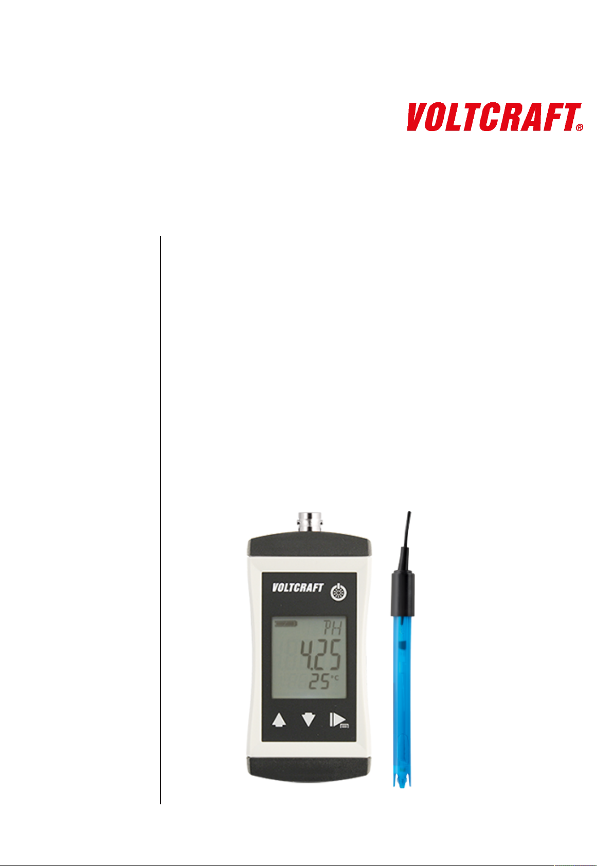
KBM-110
pH Tester
BNC connection
Waterproof
Precise and fast
Page 2

Table of contents
Table of contents
1 Legal address of the manufacturer................................................................................................... 4
2 About this documentation ................................................................................................................. 5
2.1 Foreword............................................................................................................................................... 5
2.2 Purpose of the document...................................................................................................................... 5
2.3 Correctness of content.......................................................................................................................... 5
2.4 Layout of this document........................................................................................................................ 5
2.5 Further information ............................................................................................................................... 6
3 Safety ................................................................................................................................................... 7
3.1 Explanation of safety symbols .............................................................................................................. 7
3.2 Foreseeable misuse ............................................................................................................................. 7
3.3 Safety instructions ................................................................................................................................ 8
3.4 Intended use ......................................................................................................................................... 9
3.5 Qualified personnel............................................................................................................................... 9
4 Description ........................................................................................................................................ 10
4.1 Scope of delivery ................................................................................................................................ 10
4.2 Job description.................................................................................................................................... 10
5 The product at a glance ................................................................................................................... 11
5.1 The KBM-110...................................................................................................................................... 11
5.2 Display elements ................................................................................................................................ 11
5.3 Operating elements ............................................................................................................................ 11
5.4 Connections........................................................................................................................................ 12
6 Bases for measurement ................................................................................................................... 13
6.1 pH measurement ................................................................................................................................ 13
6.1.1 Explanation ......................................................................................................................................... 13
6.1.2 pH electrode ....................................................................................................................................... 13
6.1.3 Design................................................................................................................................................. 13
6.1.4 Further information ............................................................................................................................. 14
6.1.5 Choosing a pH electrode .................................................................................................................... 14
6.1.6 Service life .......................................................................................................................................... 14
6.1.7 Care and maintenance ....................................................................................................................... 15
6.2 Redox measurement .......................................................................................................................... 15
6.2.1 Explanation ......................................................................................................................................... 15
7 Maintenance ...................................................................................................................................... 16
7.1 Operating and maintenance notices ................................................................................................... 16
7.2 Battery ................................................................................................................................................ 16
7.2.1 Battery indicator.................................................................................................................................. 16
7.2.2 Changing battery ................................................................................................................................ 16
7.3 Calibration and adjustment ................................................................................................................. 17
7.3.1 pH calibration...................................................................................................................................... 17
8 Operation........................................................................................................................................... 22
8.1 Commissioning ................................................................................................................................... 22
8.1.1 Explanation ......................................................................................................................................... 22
8.2 Configuration ...................................................................................................................................... 22
8.2.1 Explanation ......................................................................................................................................... 22
2 / 32 B-H86.0.12.DB214-1.0
Page 3

Table of contents
8.2.2 Opening the configuration menu......................................................................................................... 22
8.2.3 Configuring parameters of the configuration menu............................................................................. 23
8.2.4 Adjustment of the measuring input ..................................................................................................... 25
8.2.5 Configuring parameters of the adjustment menu................................................................................ 26
9 Error and system messages............................................................................................................ 28
10 Disposal............................................................................................................................................. 30
11 Technical data................................................................................................................................... 31
12 Service ............................................................................................................................................... 32
12.1 Manufacturer....................................................................................................................................... 32
B-H86.0.12.DB214-1.0 3 / 32
Page 4

1 | Legal address of the manufacturer KBM-110
1 Legal address of the manufacturer
Conrad Electronic SE
Klaus-Conrad-Str. 1
D-92240 Hirschau
http://www.conrad.com
WEEE reg. no. DE 28001718
4 / 32 B-H86.0.12.DB214-1.0
Page 5

KBM-110 About this documentation | 2
2 About this documentation
2.1 Foreword
Read this document carefully and familiarise yourself with the operation of the product
before you use it. Keep this document ready to hand and in the immediate vicinity of
the product so that it is available to the personnel/user for reference at all times in
case of doubt.
The product was developed according to the state of the art and fulfils the requirements of the applicable European and national Directives. All corresponding documents are available from the manufacturer.
Only technically qualified persons are permitted to carry out commissioning, operation,
maintenance and decommissioning. The qualified personnel must have carefully read
and understood the operating manual before beginning any work.
2.2 Purpose of the document
– This document describes the operation and maintenance of the product.
– Provides important information for working safely and efficiently with the product.
– In addition to the quick reference guide with all relevant legal and safety content in
hard copy, this document is a detailed reference option for the product.
2.3 Correctness of content
The contents of this document were checked for corrected and are subject to a continuous correction and updating process. This does not rule out potential errors. In the
event that errors are discovered or in case of suggestions for improvement, please inform us immediately via the indicated contact information in order to help us make this
document even more user-friendly.
2.4 Layout of this document
Description
Each chapter is explained at the beginning in the description.
Prerequisite
All mandatory prerequisites are then listed for each step.
Instruction
Tasks to be carried out by the personnel / user are represented as numbered instructions. Adhere to the sequence of the specified instructions.
Representation
Shows an illustrative instruction or a configuration of the product.
Formula
Some instructions include a formula for a general understanding of a configuration,
programming or a setting of the product.
B-H86.0.12.DB214-1.0 5 / 32
Page 6
2 | About this documentation KBM-110
Outcome of an action
Result, consequence or effect of an instruction.
Emphases
In order to simplify legibility and provide a clearer overview, various sections / information are emphasised.
– 1234 Display elements
– Mechanical controls
– Product functions
– Product labels
– Cross-reference [}p.5]
– Foot notes
2.5 Further information
Software version of the product:
– V1.2 or later
For the exact product name, refer to the type plate on the rear side of the product.
NOTE
For information about the software version, press and hold the ON button to switch on
the product for longer than 5 seconds. The series is shown in the main display and the
software version of the product is shown in the secondary display.
6 / 32 B-H86.0.12.DB214-1.0
Page 7
KBM-110 Safety | 3
3 Safety
3.1 Explanation of safety symbols
DANGER
This symbol warns of imminent danger which can result in death, severe bodily injury,
or severe property damage in case of non-observance.
DANGER
This symbol indicates danger for living tissue as well as a variety of materials, which
can be damaged or destroyed when coming into contact with this chemical. Caustic
effect, protective equipment required!
DANGER
This symbol indicates danger for all life forms, which can result in death or acute or
chromic damage to the health after inhaling, swallowing or absorbing this chemical
through the skin.
CAUTION
This symbol warns of potential dangers or harmful situations which can cause damage
to the device or to the environment in case of non-observance.
NOTE
This symbol indicates processes which can have a direct influence on operation or
can trigger an unforeseen reaction in case of non-observance.
NOTE
This symbol instructs the use of eye protection which protects the eyes from harmful
influences when working with powerful light, UV radiation, laser, chemicals, dust,
splinters or weather influences.
NOTE
This symbol instructs the use of protective gloves which offer protection from mechanical, thermal, chemical, biological or electrical hazards.
3.2 Foreseeable misuse
The fault-free function and operational safety of the product can only be guaranteed if
generally applicable safety precautions and the device-specific safety instructions for
this document are observed.
If these notices are disregarded, personal injury or death, as well as property damage
can occur.
B-H86.0.12.DB214-1.0 7 / 32
Page 8
3 | Safety KBM-110
DANGER
Incorrect area of application!
In order to prevent erratic behaviour of the product, personal injury or property damage, the product must be used exclusively as described in the chapter Description
[}p.10] in the operating manual.
– Do not use in safety / Emergency Stop devices!
– The product is not suitable for use in explosion-prone areas!
– The product must not be used for diagnostic or other medical purposes on pa-
tients!
– The product is not intended to come into direct contact with food. For measure-
ment in foods, samples must be taken and discarded after the measurement!
3.3 Safety instructions
This product has been designed and tested according to the safety requirements for
electronic measuring devices.
DANGER
Danger of breaking the electrodes!
All electrodes contain glass parts that can cause injuries when broken. There is an elevated risk of injury in connection with measurements in foods.
– Inspect the electrode before and after the measurement!
– Always measures in samples for measurements in foods. Discard these samples
after the measurement!
DANGER
Potassium chloride / potassium nitrate!
The electrode contains potassium chloride or potassium nitrate. All contact with the
skin, clothing and eyes should be avoided. Nevertheless, should contact occur, take
the following measures
– Eyes: Flush with flowing water for at least 15 minutes, seek medical attention!
– Skin: Wash with large amounts of water for several minutes!
– Clothing: Wash immediately!
– If swallowed: Drink large amounts of water, do not induce vomiting and seek med-
ical attention!
CAUTION
Erratic behaviour!
On suspicion that the product can no longer be operated without danger, it must be
decommissioned and prevented from recommissioning with appropriate labelling. The
safety of the user can be impaired by the device if, for example, if it shows visible
damage, it no longer works as specified or if it was stored for an extended period of
time under unsuitable conditions.
– Visual inspection!
– In case of doubt, send the product to the manufacturer for repair or maintenance!
8 / 32 B-H86.0.12.DB214-1.0
Page 9

NOTE
If the product is stored at a temperature above 50 °C, or is not used for an extended
period of time, the batteries must be removed. Leaks from the batteries are avoided as
a result.
NOTE
This product does not belong in children's hands!
For this purpose, also refer to
2 Technical data [}31]
3.4 Intended use
The product is designed for measuring the pH value and Redox by means of suitable
electrodes in water an aqueous media. Temperature compensation takes place automatically with a connected temperature sensor.
Application examples for this are, for example, drinking water, waste water, surface
water, swimming pools, fish breeding and process chemistry.
KBM-110 Safety | 3
See Technical data [}p.31].
3.5 Qualified personnel
For commissioning, operation and maintenance, the relevant personnel must have adequate knowledge of the measuring process and use of the measurements, for which
purpose this document makes a valuable contribution. The instructions in this document must be understood, observed and followed.
In order to ensure that no risks arise from the interpretation of the measurements in
the concrete application, the user must have additional technical knowledge, because
the user is liable in case of damage/danger due to misinterpretation as a result of inadequate technical knowledge.
B-H86.0.12.DB214-1.0 9 / 32
Page 10

4 | Description KBM-110
4 Description
4.1 Scope of delivery
Please check to ensure the completeness of the product after opening the package.
You should find the following components:
– Quick reference guide
– Handheld measuring device, ready for operation, including batteries
– Electrode GE 114 WD
4.2 Job description
The product offers precision, speed and reliability in a compact, ergonomic housing.
Additional impressive features include the dust-proof and waterproof design in accordance with IP 65/67 and the 3-line illuminated display, which offers overhead display at
the push of a button. The product can be switched on, switched off and configured and
the measurements and parameters can be adjusted and held with the operating elements. The product is equipped with a BNC socket for connection of different electrodes, as well as with two 4 mm banana sockets for connection of temperature
sensors or a reference electrode.
10 / 32 B-H86.0.12.DB214-1.0
Page 11
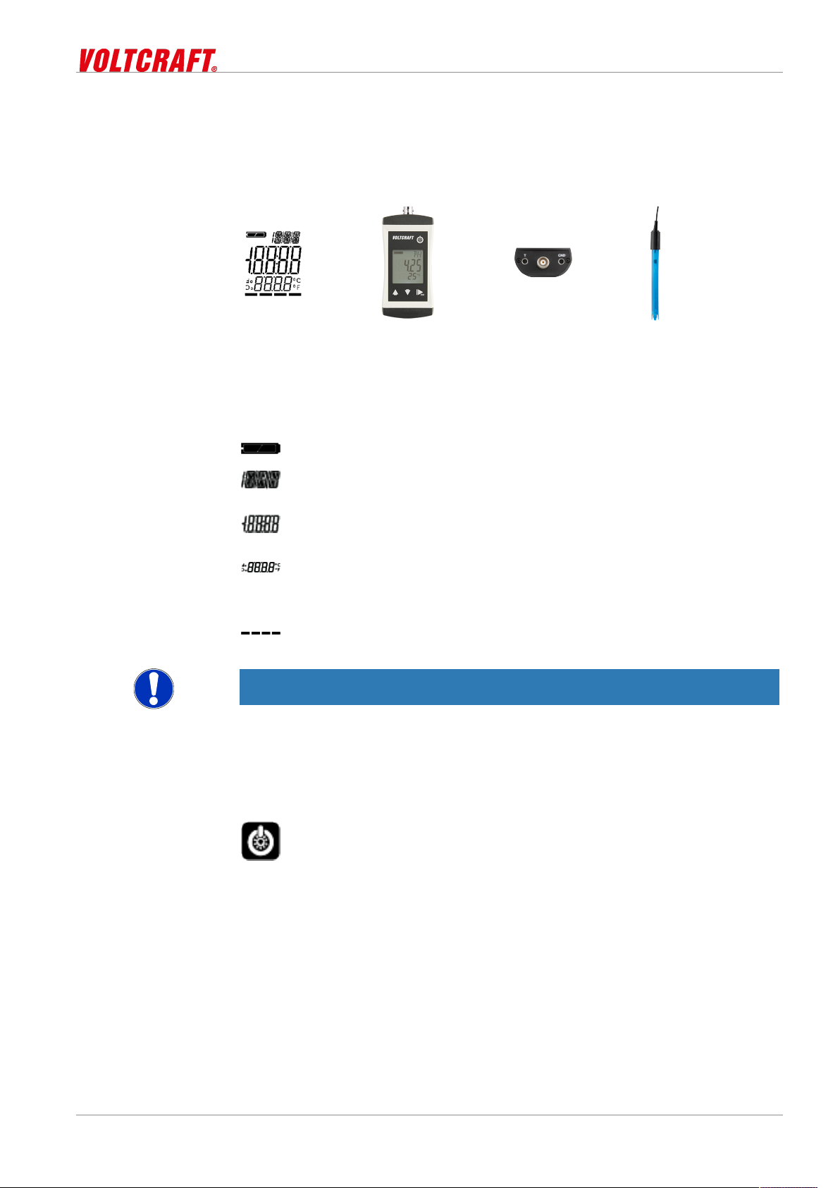
KBM-110 The product at a glance | 5
5 The product at a glance
5.1 The KBM-110
LCD Display KBM-110 BNC connection and 2x4
5.2 Display elements
Display
Battery indicator Evaluation of the battery status
Unit display Display of units, if applicable, with unstable symbol
Main display Measurement of the current pH value or value for
Auxiliary display Corresponding temperature for the displayed pH
Bar graph Progress for calibration and visualisation of the
NOTE
The unit display shows a rotating circle segment in the first position as long as the
measurement is unstable, if the position is unoccupied by the unit display.
mm banana
KBM-110
or type of mode, min/max/hold
min/max/hold
value with unit. Measured temperatures are displayed with a decimal place, adjusted without.
electrode evaluation
5.3 Operating elements
On / Off button
Press briefly Switch on the product
Activate / deactivate lighting
Long press Switch off the product
Reject changes in a menu
B-H86.0.12.DB214-1.0 11 / 32
Page 12

5 | The product at a glance KBM-110
Up / Down button
Press briefly Display of the min/max value
Change value of the selected parameter
Long press Reset the min/max value of the current measure-
ment
Both simultaneously Rotate display, overhead display
Function key
Press briefly Freeze measurement
Return to measurement display
Call up next parameter
Long press, 2s
Long press, 4s
Start menu configuration, (ONF appears in the display
Start automatic calibration, (AL appears in the display
5.4 Connections
BNC connection Connection for electrode
2x 4mm banana Connection for temperature sensor or reference
CAUTION
Waterproofness!
Waterproofness is only guaranteed for plug connections in the plugged-in state in
combination with waterproof cable plugs.
– Protect contacts from soiling and moisture!
NOTE
The temperature measurement can be influenced by conductive liquids on the banana
sockets. We recommend always keeping the connections dry.
Un/locking with rotating ring on the cable plug
electrode
12 / 32 B-H86.0.12.DB214-1.0
Page 13

KBM-110 Bases for measurement | 6
6 Bases for measurement
6.1 pH measurement
6.1.1 Explanation
The pH value describes the acidic or alkaline behaviour of an aqueous solution. A pH
value below 7 is acidic, a value above 7 is alkaline. A pH value of 7 is neutral.
The pH measurement is very precise, but also sensitive. The measured signals are
very weak and high-ohmic. This is the case, in particularly in low-ion media.
NOTE
In order to detect the pH value of a solution, it should always be recorded together
with the measurement temperature, because most liquids change their pH value with
the temperature.
The following must be observed:
– avoid interference, electrostatic charges, etc.
– keep plug contacts clean and dry
– prevent electrodes which do not have any special waterproof versions from exten-
ded immersion above the shaft
– calibrate electrodes sufficiently often. The can range from every hour to several
weeks, depending on the electrode and the application
– Use a suitable electrode
6.1.2 pH electrode
NOTE
Normally, so-called pH single-rod measuring chains are used. They include all necessary components that are integrated in an electrode.
6.1.3 Design
1. Coaxial cable
2. Reference electrode
3. Measuring electrode
4. Refill opening
5. Electrolyte
6. Internal buffer
7. Diaphragm
8. Glass membrane / source layer
The diaphragm, which establishes a connection between the electrolyte and the liquid
to be measured, can be designed in different ways. Clogging or soiling of the diaphragm is a frequent cause of a malfunctioning or sluggish electrode. Always handle
the glass membrane with extreme care. The so-called source layer forms there. This
is crucial for the measurement and must always be kept moist.
There are also electrodes with integrated temperature sensors.
B-H86.0.12.DB214-1.0 13 / 32
Page 14

6 | Bases for measurement KBM-110
6.1.4 Further information
A pH electrode is a wear part. If the signal is very slow or the required values are no
longer observed after careful cleaning and possible regeneration, the electrode must
be replaced. When using the electrodes, be aware that various substances in aqueous
solutions can corrode glass and that chemicals can produce a chemical reaction with
the KCl solution in the electrode, which can result in blockage of the diaphragm.
– In solutions that contain proteins, such as for measurements in medical and biolo-
gical applications, KCl can cause denaturation of the protein.
– Coagulated paints
– Solutions that contain high concentrations of silver ions
Substances that accumulate on the glass membrane or the diaphragm affect the
measurement and must be removed regularly. This can be achieved for example with
automatic cleaning systems.
6.1.5 Choosing a pH electrode
The GE 114 WD or GE 100 can be used for most applications. However, some areas
of application require special electrodes.
– GE 100 BNC is a universal electrode with two ceramic diaphragms and liquid elec-
trolyte.
– GE 101 BNC is preferably used for small sample amounts. It comprises a glass
electrode with two ceramic diaphragms and liquid electrolyte.
– GE 104 BNC is preferably used for measurements in low-ionic media, such as
rainwater, aquarium water and deionised water.
– GE 114 WD is a universally applicable, durable and low-maintenance gel elec-
trode with Pellon diaphragm. It can be used for measurements in drinking water,
swimming pools, aquaria and slightly contaminated waste water.
– GE 117 BNC is a temperature-compensated gel electrode with two ceramic dia-
phragms and PH 13.5 cable screw coupling.
– GE 120 BNC is an insertion electrode and is preferably used for measurements in
cheese, fruit and meat. For measurements in products containing proteins, the
electrode must be cleaned with a special cleaner. For this purpose, we recommend the GRL 100 pepsin cleaning solution.
– GE 125 BNC is a waterproof, universally applicable, durable and low-maintenance
gel electrode with ceramic diaphragm. It can be immersed above the shaft for an
extended time.
– GE 151 BNC is a glass electrode and is preferably used in galvanic applications
for paints and lacquers.
– GE 173 BNC is an alkaline-resistant glass electrode with ground diaphragm and
gel electrolyte for chemical and waste water applications.
6.1.6 Service life
The service life of electrodes is normally at least 8 to 10 months. When cared for properly, this can usually increase to more than 2 years. The actual life will vary depending
on the particular application.
14 / 32 B-H86.0.12.DB214-1.0
Page 15

KBM-110 Bases for measurement | 6
6.1.7 Care and maintenance
NOTE
The GAK 1400 working and calibration set includes all necessary products for calibration, care and maintenance of the electrode. Normal cleaning takes place with the
GRL 100 pepsin cleaning solution into which the electrode is immersed for 5 minutes
before being rinsed off with clean water.
NOTE
Crystallisation of the 3 mol/l KCL solution is unavoidable. Crystallised potassium chloride on the protective cap and shaft can easily be removed with a fingernail or cloth
and is therefore not a defect or grounds for complaint.
Dirty electrodes must be cleaned. The suitable cleaning agents for the pH glass membrane are listed in the table below.
Impurities Cleaners
General residue Mild detergent
Inorganic coatings Commercially available liquid glass clean-
Metal compounds 1 mol/l HCl solution or GRL 100 pepsin
Oil and grease Special cleaner or solvent
Biological coatings with protein 1% pepsin enzyme in 0.1 molar GRL 100
Resin lignins Acetone
Extremely resistant residues Hydrogen peroxide or sodium hypochlor-
ers
cleaning solution
HCl solution
ide
The material of the pH probe must always be protected. Plastic shafts must not be
cleaned in solvents, etc. If in doubt, contact the manufacturer to inquire about suitable
cleaners for the existing electrode. This is also important in the case of aggressive
substances or other substances that are not primarily water-based!
6.2 Redox measurement
6.2.1 Explanation
The Redox potential 0RP specifies the extent to which the measured sample has an
oxidising or reducing effect relative to the standard hydrogen electrode.
This potential is frequently used in swimming pools as a measured variable for the disinfecting effect of a chlorination. For aquaria, the Redox value is also an important
parameter, because fish can only live within a specific Redox range. The measurement is also important in drinking water preparation, waste water monitoring and in industrial applications.
Measurement takes place relative to the widespread silver/silver-chloride system with
3 mol/l KCL electrolyte. The measurements can be read directly (mV setting) or automatically with the mVH unit setting and temperature compensation is calculated based
on the standard hydrogen electrode reference system.
Calibration comparable to the pH measurement does not take place for the Redox
measurement. However, the suitability of the electrodes can always be checked with
Redox testing solutions, such as GRP 100.
B-H86.0.12.DB214-1.0 15 / 32
Page 16
7 | Maintenance KBM-110
7 Maintenance
7.1 Operating and maintenance notices
NOTE
The product and electrode must be handled with care and used in accordance with the
technical data. Do not throw or strike.
NOTE
Plugs and sockets must be protected from soiling.
NOTE
If the product is stored at a temperature above 50 °C, or is not used for an extended
period of time, the batteries must be removed. Leaks from the batteries are avoided as
a result.
NOTE
The electrode should be stored in dry rooms at a temperature between 10 °C and 30
°C. If the storage temperature range is exceeded or undercut, the electrode can be
destroyed. It should always be stored wet in 3 mol/l KCl. Extended storage in distilled
or deionised water will result in depletion of the reference electrolytes.
NOTE
The pH electrode included in the scope of supply should be arranged vertically upwards with the connecting cable. A slight angle of inclination does not impair the
measurement.
7.2 Battery
7.2.1 Battery indicator
If the empty frame in the battery display blinks, the batteries are depleted and must be
replaced. However, the device will still operate for a certain length of time.
If the BAT display text appears in the main display, the battery voltage is no longer adequate for operation of the product. Now the battery is fully depleted.
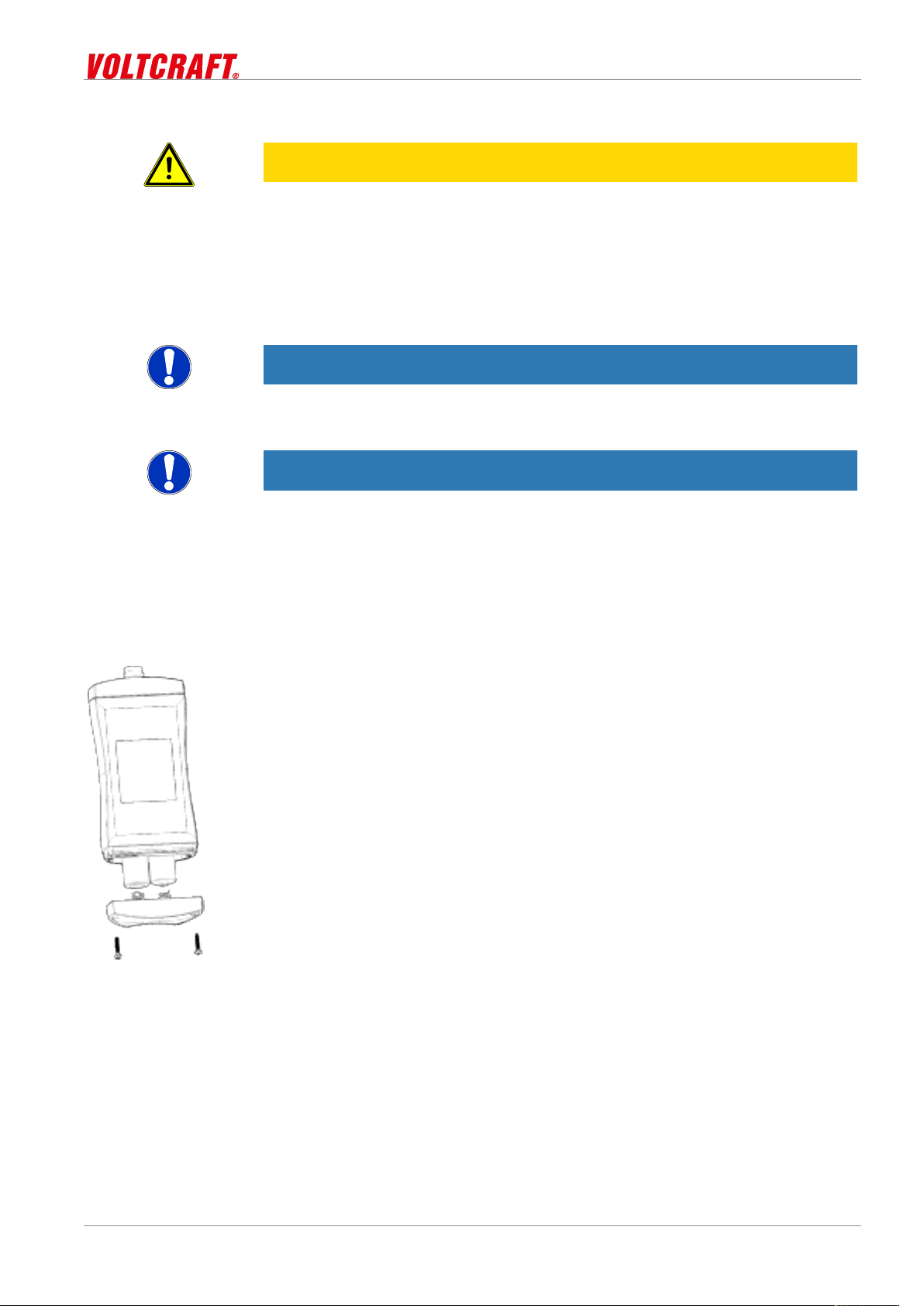
7.2.2 Changing battery
DANGER
Danger of explosion!
Using damaged or unsuitable batteries can generate heat, which can cause the batteries to crack and possibly explode!
16 / 32 B-H86.0.12.DB214-1.0
Page 17
KBM-110 Maintenance | 7
– Only use high-quality and suitable alkaline batteries!
CAUTION
Damage!
If the batteries have different charge levels, leaks and thus damage to the product can
occur.
– Use new, high-quality batteries!
– Do not use different types of batteries!
– Remove depleted batteries and dispose of them at a suitable collection point!
NOTE
Unnecessary screwing places the water-tightness of the product, among other things,
at risk and should be avoided.
NOTE
Read the following handling instructions before replacing batteries and follow them
step by step. If disregarded, the product could be damaged or the protection from
moisture could be diminished.
Description
Prerequisites
Instruction
Outcome of an action
Proceed as follows to replace the batteries.
– The product is switched off.
– A suitable PH1 is available
1. Unscrews the Phillips screws and remove the cover.
2. Carefully replace the two Mignon AA batteries. Ensure that the polarity is correct!
It must be possible to insert the batteries in the correct position without using
force.
3. The O-ring must be undamaged, clean and positioned at the intended depth. In order to facilitate assembly and avoid damage, a suitable grease can be applied.
4. Fit the cover on evenly. The O-ring must remain at the intended depth!
5. Tighten the Phillips screws.
The product is now ready for use again.
7.3 Calibration and adjustment
7.3.1 pH calibration
Description
B-H86.0.12.DB214-1.0 17 / 32
In order to obtain reliable measurements, the device and electrode must be aligned
with each other. In pH measurement, this is referred to as a calibration. In order to
conduct a pH measurement, proceed as follows.
Page 18
7 | Maintenance KBM-110
For automatic calibration, open the Calibration menu. See Automatic pH calibration
[}p.19].
Prerequisite
Instruction
Outcome of an action
– The pH electrode and, if applicable, a temperature sensor are inserted in the
product.
– The product is switched on.
1. Carefully remove the protective cap from the electrode.
2. Rinse off the electrode with distilled or deionised water.
Now, the product can be calibrated.
7.3.1.1 Explanation
The following steps describe how to calibrate the product.
To achieve a precise measurement, observe the following points.
NOTE
If possible, the calibration range should overlap the measuring range. To achieve this,
it is recommended to use buffer solutions for measurements as follows:
– below pH 7 uses pH 7.0 and pH 4.0 buffer
– above pH 7 uses pH 7.0 and pH 10.0 buffer
Description
NOTE
Calibrations are only possible in a temperature range from 0 °C to 60 °C! We recommend performing calibration at temperatures between 10 °C and 40 °C.
NOTE
Calibration should be conducted at the same temperature used for the measurement
in the medium. To equalize the temperatures of the buffer solutions and electrode,
they should be stored together for a while in a place that is protected against draught.
NOTE
If a temperature sensor is not connected, measure the temperature of the buffer solution with a thermometer. The exact value of the buffer solution is temperature dependent and can be determined based on the tables provided.
NOTE
Always use fresh buffer solutions!
7.3.1.2 Buffer solutions
At least one buffer solution is required to calibrate the product. In the process, you
have the option of using a ready-to-use PHL buffer solution or mixing the solution
yourself with GPH buffer capsules - refer to the instructions.
Colour 10 °C 20 °C 25 °C 30 °C 40 °C
PHL 4.0 Red 4.02 4.00 4.01 4.01 4.01
PHL 7.0 Green 7.06 7.02 7.00 6.99 6.97
PHL 10.0 Blue 10.18 10.07 10.01 9.97 9.89
18 / 32 B-H86.0.12.DB214-1.0
Page 19
Prerequisite
Instruction
Outcome of an action
KBM-110 Maintenance | 7
Ready-to-use buffer solutions in 250 ml dosing bottles with a dosing volume of 20 to 25 ml.
– Plastic bottle
– approx. 100 ml of distilled water
– Buffer capsule
Colour 10 °C 20 °C 25 °C 30 °C 40 °C
GPH 4.0 Orange 3.99 3.99 4.01 4.01 4.03
GPH 7.0 Green 7.06 7.01 7.00 6.99 6.98
GPH 10.0 Blue 10.18 10.06 10.01 9.97 9.89
GPH 12.0 White 12.35 12.14 12.00 11.89 11.71
Buffer capsules for 100 ml buffer solution
1. Fill a plastic bottle with approx. 100 ml of distilled water.
2. Open the buffer capsule carefully by twisting the capsule halves and pulling. It
should be ensured that nothing is spilled. They can also be used without opening
them; opening the capsules only reduces to time for dissolving.
3. Place the buffer capsule and its contents in the plastic bottle.
4. Wait at least 3 hours.
5. Shake well before using for the first time.
Then you can begin with calibration of the product.
Description
Prerequisite
Instruction
7.3.1.3 Automatic pH calibration
The following steps describe how to calibrate the product automatically.
– The product is switched on.
– The pH electrode and, if applicable, a temperature sensor are inserted in the
product.
– Ready-to-use GPH 7.0 buffer solution.
– Ready-to-use GPH 4.0 or GPH 10.0 buffer solution.
NOTE
Automatic calibration can also be carried out with the pre-mixed PHL buffer solutions.
Since the temperature compensation relates to the GPH capsules, an error of a few
hundredths pH should be taken into account, depending on the temperature. Refer
also to the differences in the tables of the buffer solutions in Buffer solutions [}p.18]
and --- FEHLENDER LINK ---.
1. Press the Function key for 4 seconds to open the Calibration menu. (AL appears in
the display.
2. Release the Function key.
3. PK 7 appears in the display.
4. Place the electrode in the GPH 7.0 buffer solution.
5. The product determines the correct value automatically. If the value is determined,
the display flashes and an acoustic signal is issued to indicate a change to the
next calibration point.
6. If the temperature sensor is not inserted, enter the temperature of the buffer solution by pressing the Up key and Down key and confirm the entry by pressing the
Function key again.
7. PK 4 and PK 10 alternate in the display.
8. Then, rinse the electrode with distilled or deionised water.
B-H86.0.12.DB214-1.0 19 / 32
Page 20
7 | Maintenance KBM-110
9. Place the electrode in the second buffer solution. The product recognises whether
it is a PK 4 or PK 10 buffer solution automatically.
10. If the temperature sensor is not inserted, enter the temperature of the buffer solution by pressing the Up key and Down key and confirm the entry by pressing the
Function key again.
11. Then, rinse the electrode again with distilled or deionised water.
Outcome of an action
After successful completion of the calibration the assessment of the electrode condition is displayed briefly in percent. Then, the current measurement is shown in the display again. A low value can be the result of the age of the electrode, contaminated or
old buffer solutions or impurities on the BNC connector.
If the calibration is not completed successfully an error message is displayed. (AL ERR.
appears in the display. See Error and system messages [}p.28]. Confirm the error
message pressing the Function key. The product restarts and the standard value for
the zero point and gradient are restored.
For this purpose, also refer to
2 Buffer solutions [}18]
7.3.1.4 Manual 1-point pH calibration
Description
The following steps describe how to perform a 1-point pH calibration.
Prerequisite
Instruction
Outcome of an action
NOTE
A 1-point calibration is only advantageous if measurement takes place in a narrow
range around the calibration point. A reliable electrode evaluation is not possible in
this case. We recommend conducting a 2-point calibration, because a 1-point calibration only entails a shift of the zero point.
– An arbitrary buffer solution is available.
1. Press the Function key for 2 seconds to open the Configuration menu.
2. (ONF appears in the display. Release the Function key.
3. The parameter SET.T appears if the temperature sensor is not plugged in. If the
temperature sensor is plugged in, you jump to the next point.
4. Enter the temperature of the buffer solution by pressing the Up key and Down key
and confirm the entry by pressing the Function key again.
5. The PK.OF parameter appears in the display.
6. Place the electrode in the buffer solution.
7. Wait until the display value is stable.
8. Adjust the value corresponding to the buffer solution with the Up key and Down key
and confirm the entry by pressing the Function key again for 2 seconds.
9. Then, rinse the electrode again with distilled or deionised water.
After successful completion of the calibration the assessment of the electrode condition is displayed briefly in percent. Then, the current measurement is shown in the display again. A low value can be the result of the age of the electrode, contaminated or
old buffer solutions or impurities on the BNC connector.
If the calibration is not completed successfully an error message is displayed. (AL ERR.
appears in the display. See Error and system messages [}p.28].
7.3.1.5 Manual 2-point pH calibration
Description
20 / 32 B-H86.0.12.DB214-1.0
The following steps describe how to perform a 2-point pH calibration.
Page 21
KBM-110 Maintenance | 7
Prerequisite
Instruction
– A buffer solution with a value between pH 6.75 and pH 7.25 is available.
– A second buffer solution with a value below pH 6 and above pH 8 is available.
1. Press the Function key for 2 seconds to open the Configuration menu.
2. (ONF appears in the display. Release the Function key.
3. The parameter SET.T appears if the temperature sensor is not plugged in. If the
temperature sensor is plugged in, you jump to the next point.
4. Enter the temperature of the buffer solution by pressing the Up key and Down key
and confirm the entry by pressing the Function key again.
5. The PK.OF parameter appears in the display.
6. Place the electrode in the buffer solution with a value between pH 6.75 and pH
7.25.
7. Wait until the display value is stable.
8. Adjust the value corresponding to the buffer solution with the Up key and Down key
and confirm the entry by pressing the Function key.
9. The PK.SL parameter appears in the display.
10. Place the electrode in the second buffer solution with a value below pH 6 or above
pH 8.
NOTE
Outcome of an action
A gradient compensation with buffer solutions between pH 6 and pH 8 is not possible.
With entry of the compensation value, the resulting gradient value is calculated imme-
diately and (AL ERR.2 or (AL ERR.3 appears in the display instead of the measurement of
the values are invalid.
11. Wait until the display value is stable.
12. Adjust the value corresponding to the buffer solution with the Up key and Down key
and confirm the entry by pressing the Function key.
13. Then, rinse the electrode again with distilled or deionised water.
After successful completion of the calibration the assessment of the electrode condition is displayed briefly in percent. Then, the current measurement is shown in the display again. A low value can be the result of the age of the electrode, contaminated or
old buffer solutions or impurities on the BNC connector.
If the calibration is not completed successfully an error message is displayed. (AL ERR.
appears in the display. See Error and system messages [}p.28]. Confirm the error
message pressing the Function key. The product restarts and the standard value for
the zero point and gradient are restored.
B-H86.0.12.DB214-1.0 21 / 32
Page 22
8 | Operation KBM-110
8 Operation
8.1 Commissioning
8.1.1 Explanation
Description
Prerequisite
Instruction
Outcome of an action
The product is switched on with the On/Off button. It may be necessary to configure
the product after switching on. See Configuration [}p.22].
– Sufficiently full batteries are inserted in the product.
– A suitable pH electrode is plugged in.
– Press On/Off button.
Information about the configuration of the product appears in the display.
POFF
T.OF
T.SL
(AL
The product is now ready for measurement.
Automatic shutoff
Zero point correction
Gradient correction
Calibration Blinks if no valid calibration is available
NOTE
The product must be calibrated to the electrode prior to starting the measurement. If
the electrode is chosen, re-calibration is necessary. See Calibration and adjustment
service.
8.2 Configuration
8.2.1 Explanation
The following steps describe how to adapt the product for your purposes.
Automatic shut-off activated. The product is
switched off if no buttons have been pressed after
the adjusted time
If a zero point correction of the temperature sensor
was made
If a gradient correction of the temperature sensor
was made
NOTE
There are various configuration parameters available depending on the product version and configuration. They can differ depending on the product version and configuration.
8.2.2 Opening the configuration menu
Description
Prerequisite
Instruction
22 / 32 B-H86.0.12.DB214-1.0
In order to configure the product, you must first open the Configuration menu. The
menu is opened as shown in the illustration.
– The product is switched on.
1. Press the Function key for 2 seconds to open the Configuration menu.
2. (ONF appears in the display. Release the function key.
Page 23
Representation
Outcome of an action
KBM-110 Operation | 8
3. By briefly pressing the Function key, you can scroll through the parameters. Select
the parameter you would like to configure.
4. When you have selected the desired parameter, change the parameter to the desired value with the Up button and the Down button.
5. The changes are saved after running through the entire Configuration menu. STOR
appears in the display. The Configuration menu can be exited from any arbitrary
parameter by pressing and holding the Function key for 2 seconds. The changes
made up that point are saved.
Call up menu Next parameter Change value Save changes Discard
changes
2s Press: Single
step
Hold: Rapid
change
The Configuration menu is closed after the last parameter.
2s 2s
NOTE
If the product is switched off without saving the configuration, the last save value is reproduced on the next start-up of the product.
Description
Prerequisite
Instruction
Representation
8.2.3 Configuring parameters of the configuration menu
The following representation shows the available parameters and various configuration options.
– The Configuration menu is open. See Opening the configuration menu [}p.22].
1. Select the desired parameter you would like to configure.
2. Adjust the desired configuration in the selected parameter with the Up button and
Down button.
3. The available configuration options are listed for each parameter in the following
representation.
Parameter Values Meaning
Setting the temperature
SET.T
-5 .. 105
Setting the zero point
PK.OF
Current measurement
Only without temperature sensor plugged in
Adjustable temperature value in °C, or in °F 23 ..
221
Setting of the zero point for calibration of the pH
measurement. If a calibration cannot be carried out,
continue with the function key
B-H86.0.12.DB214-1.0 23 / 32
Page 24

8 | Operation KBM-110
Setting the gradient
PK.SL
Current measurement
Setting of the gradient for calibration of the pH
measurement. If a calibration cannot be carried out,
continue with the function key
Input
INP
PK
0RP mV
Redox in mV, relative to silver / silver chloride electrode
0RP mVH
Redox in mVH, relative to hydrogen electrode
Temperature unit
UN,T
°(
°F
Temperature display in °C
Temperature display in °F
Alarms
AL.
OFF
ON
No active alarm
Alarm alerting via text display, acoustic signal and
flashing of the backlighting
BEEP
L,TE
Alarm alerting via text display and acoustic signal
Alarm alerting via text display and flashing of the
backlighting
AL.LO Depending on the setting of the parameter value INP
PK 0.00 .. AL.K,
mV
mV
H
-1500 .. AL.K,
-1293 .. AL.K,
AL.K, Depending on the setting of the parameter value INP
PK AL.LO .. 14.00
mV
mV
H
AL.LO .. 1500
AL.LO .. 1707
Shut-off time
POFF
OFF
15 30 60 120 240
No automatic shut-off
Automatic shut-off after a selected time in minutes,
during which no buttons have been pressed
24 / 32 B-H86.0.12.DB214-1.0
Page 25
Outcome of an action
KBM-110 Operation | 8
Backlighting
L,TE
OFF
15 30 60 120 240
ON
Factory settings
IN,T
NO
YES Reset product to factory settings. IN,T DONE appears
The changed value is saved and the Configuration menu is closed. STOR appears in
the display. If necessary, the product is restarted automatically in order to adopt the
changed values.
Backlighting deactivated
Automatic shut-off of the backlighting after a selected time in seconds, during which no buttons have
been pressed
No automatic shut-off of the backlighting
Use current configuration
in the display
NOTE
Description
Prerequisites
Instruction
Representation
The configuration is closed if no button is pressed for 2 minutes. Any changes made
up to that point are not saved. C.END appears in the display.
There is no active timeout with the parameters PK.OF and PK.SL.
8.2.4 Adjustment of the measuring input
The temperature input can be adjusted with the zero point correction and the gradient
correction. If an adjustment is made, you change the pre-adjusted factory settings.
This is signalled with the T.OF or T.SL when the product is switched on. The standard
settings of the zero point value and the gradient value is 0.00. It signals that no correc-
tion is made.
In order to adjust the product, you must first open the Adjustment menu. The menu is
opened as shown in the illustration.
– Sufficiently full batteries are inserted in the product.
– The product is switched off.
– Ice water, regulated precision water baths or a water bath with a reference meas-
urement are available as a reference.
1. Press and hold the Down button.
2. Press the On/Off button to switch on the product and open the Configuration
menu. Release the Down button. The display shows the first parameter.
3. By briefly pressing the Function key, you can scroll through the parameters. Select
the parameter you would like to configure.
4. When you have selected the desired parameter, change the parameter to the desired value with the Up button and the Down button.
5. In order to save the new parameter value, press and hold the Function key for
longer than 1 second.
Call up menu
Hold Release
B-H86.0.12.DB214-1.0 25 / 32
Page 26

8 | Operation KBM-110
Outcome of an action
8.2.5 Configuring parameters of the adjustment menu
Description
Prerequisites
Instruction
Representation
The Configuration menu is closed after the last parameter.
NOTE
If the product is switched off without saving the configuration, the last save value is reproduced on the next start-up of the product.
The following representation shows the available parameters and various configuration options.
The Adjustment menu is open. See Adjustment of the measuring input [}p.25].
1. Select the desired parameter you would like to configure.
2. Adjust the desired configuration in the selected parameter with the Up button and
Down button.
3. The available configuration options are listed for each parameter in the following
representation.
Parameter Values Meaning
Zero point correction
Formula
Example calculation
T.OF
0.00
-5.00 .. 5.00
No zero point correction
Zero point correction in °C. and/or at °F -9.00 ..
9.00
Gradient correction of the temperature
T.SL
0.00
-5.00 .. 5.00
No gradient correction
Gradient correction in %
Gradient correction °C:
Display = (measured value – T.OF) * (1 + T.SL / 100)
Gradient correction °F:
Display = (measured value – 32 °F – T.OF) * (1 + T.SL / 100) + 32 °F
– Zero point correction T.OF to 0.00
– Gradient correction T.SL to 0.00
– Display unit UNIT to °C
– Display in ice water -0.2 °C
– Display in ice water setpoint T.OF = 0.0 °C
– Display in water bath 36.6 °C
– Display in water bath setpoint T.SL = 37.0 °C
– T.OF = display zero point correction – setpoint zero point
– T.OF = -0.2 °C – 0.0 °C = -0.2 °C
– T.SL = (setpoint gradient correction / (display gradient correction – T.OF) – 1) *100
– T.SL = (37.0 °C / (36.6 °C – (-0.2)) -1) *100 = 0.54
Outcome of an action
26 / 32 B-H86.0.12.DB214-1.0
The changed value is saved and the Configuration menu is closed.
Page 27

KBM-110 Operation | 8
NOTE
If the product is switched off without saving the configuration, the last save value is reproduced on the next start-up of the product.
B-H86.0.12.DB214-1.0 27 / 32
Page 28

9 | Error and system messages KBM-110
9 Error and system messages
Display Meaning Possible causes Remedy
>(AL<
No display,
unclear characters or no
response
when buttons are
pressed
BAT
BAT LO
(AL ERR.1
(AL ERR.2
(AL ERR.3
(AL ERR.4
(AL ERR.5
ERR.1
ERR.2
SYS ERR
Error during the last
calibration
Battery depleted
System error
Product is defective
Battery depleted Battery depleted Replace battery
Battery depleted Battery depleted Replace battery
Neutral buffer not allowed
Slope is too low Incorrect buffer solu-
Slope is too high Incorrect buffer solu-
Incorrect calibration
temperature
Time exceeded during automatic calibration
Measuring range exceeded
Measuring range is
undercut
System error Error in the product Switch product on/off
Faulty calibration Conduct a new calibration
Battery depleted
Error in the product
Product is defective
Incorrect buffer solution used
Buffer solution is
contaminated
Electrode contaminated or defective
tion used
Buffer solution is
contaminated
Electrode contaminated or defective
tion used
Buffer solution is
contaminated
Electrode contaminated or defective
Temperature too low
or too high
Unstable electrode
signal
Buffer solution is
contaminated
Measurement too
high
Incorrect electrode
connected
Electrode or product
defect
Measurement too
low
Incorrect electrode
connected
Electrode or product
defect
Replace battery
Send in for repair
Use fresh buffer solution
Clean electrode, re-calibrate
Replace electrode
Use fresh buffer solution
Clean electrode, re-calibrate
Replace electrode
Use fresh buffer solution
Clean electrode, re-calibrate
Replace electrode
Range of 0..60 °C
Stirring of the buffer solution
Clean the electrode
Use fresh buffer solution
Restart calibration
The measurement is above
the permissible range
Check electrode
Send in for repair
The measurement is below
the permissible range
Check electrode
Send in for repair
28 / 32 B-H86.0.12.DB214-1.0
Page 29

KBM-110 Error and system messages | 9
Replace batteries
Send in for repair
B-H86.0.12.DB214-1.0 29 / 32
Page 30

10 | Disposal KBM-110
10 Disposal
NOTE
The device must not be disposed of with household waste. If the product is disposed
of, please take it to a municipal collection point, where it will be transported to a disposal company in accordance with requirements of hazardous goods laws. Otherwise,
return it to us, freight prepaid. We will then arrange for the proper and environmentally-friendly disposal. Please dispose of empty batteries at the collection points intended for this purpose.
30 / 32 B-H86.0.12.DB214-1.0
Page 31

KBM-110 Technical data | 11
11 Technical data
Measuring range pH Redox Temperature
0.00 .. 14.00 pH -1500 .. +1500 mV
1293 .. +1707 mV
Accuracy (at nominal temperature)
Temperature compensation -5 .. 105 °C (or 23 .. 221 °F) Not compensated
Input resistance ca. 1012 Ohm
Nominal temperature 25°C
Measuring
cycle
Connections pH, Redox BNC connection for electrode
Temperature Banana 4mm, Pt1000 2-wire
Display 3-line segment LCD, additional symbols, illuminated (adjustable white, perman-
Additional functions Min/Max/Hold
pH calibration Manual 1- or 2-point or automatic 2-point calibration
Housing Break-proof ABS housing
Protection rating
Dimensions
L*W*H [mm]
and weight
Operating conditions -20 to 50 °C; 0 to 95 % r.h. (temporarily 100 % r.h.)
Storage temperature -20 to 70 °C
Current supply
Auto-power-OFF function The device switches off automatically if this is activated
Directives and standards The devices conform to the following Directives of the Council for the harmon-
Current requirement/
battery life
Battery indicator
± 0.02 pH ± 1 digit ± 0.1% FS ± 1 Digit ± 0.3 °C
approx. 2 measurements per second
ent illumination)
IP65 / IP67 (only with electrodes identified as waterproof in the connected state
for devices with BNC connection)
108 * 54 * 28 mm without BNC plug
130 g, incl. battery, without electrode
190 g, incl. battery and electrode
2*AA battery (included in the scope of delivery)
approx. 0.7 mA, approx. 2.5 mA with lighting
Service life > 3000 hours with alkaline batteries (without backlighting)
4-stage battery status indicator,
Replacement indicator for depleted batteries: "BAT"
isation of legal regulations of the Member States:
2014/30/EU EMC Directive
2011/65/EU RoHS
Applied harmonised standards:
EN 61326-1:2013 Emission limits: Class B
Immunity according to Table 2
Additional errors: < 0.5 % FS
EN 50581:2012
H
-5 .. 105 °C
23 .. 221 °F
The device is intended for mobile use and/or stationary operation in the scope
of the specified operating conditions without further limitations.
B-H86.0.12.DB214-1.0 31 / 32
Page 32

12 | Service KBM-110
12 Service
12.1 Manufacturer
If you have any questions, please do not hesitate to contact us:
Contact
VOLTCRAFT
Distributed by
Conrad Electronic SE
Klaus-Conrad-Str. 1
92240 Hirschau, Germany
Tel.: +49 9604 40 87 87
Fax: +49 180 5 312110
kundenservice@conrad.de
WEEE reg. no. DE 28001718
32 / 32 B-H86.0.12.DB214-1.0
 Loading...