How it Works
Log In / Sign Up
Buy Points
How it Works
FAQ
Contact Us
Questions and Suggestions
Users
VOLTCRAFT
Loading...
D
DL-141TH
8
DL-141 TH2K
3
DL-151AN
4
DL-160S
4
DL-161AN
3
DL-161S
5
DL-180THP
3
DL-181THP
4
DL-191A
4
DL-191V
5
DL-200
3
DL–200T
7
DL-201 THM
3
DL–210TH
8
DL–220THP
8
DL-240K
3
DL-250V
3
DL-260A
3
DLA-3L 16
3
DLA-3L 32
3
DO-10
DO-100
5
DO-10i
DO-20
3
DO-400
8
DO-50
DO-506
DO-55
DOM-100
2
DOT-150
7
DPM1L32-D
7
DPM1L32-D Plus
DPM-314D
4
DPM3L80-D
3
DPM 3L85-D
DPM 982-T
DPPS-16-30
6
DPPS-16-40
8
DPPS-16-60
8
DPPS-32-15
8
DPPS-32-20
8
DPPS-32-30
8
DPPS-60-10
8
DPPS-60-15
8
DPPS-60-8
8
Drehstrom Adapter
2
DS-02
3
DSA Series Spectrum Analyzer
DSO-1000D Series
DSO1000E Series
DSO-1022
2
DSO-1022 M
2
DSO-1052 USB
4
DSO-1062D
12
DSO-1062D-VGA
4
DSO-1074D
5
DSO-1082 USB
4
DSO-1084E
6
DSO-1084F
6
DSO-1102D
10
DSO-1102 USB
5
DSO-1104D
4
DSO-1104E
6
DSO-1104F
8
DSO-1202D
8
DSO-1204E
7
DSO-1204F
6
DSO-1254E
6
DSO-1254F
6
DSO-2020 USB
6
DSO-2074G
3
DSO-2090 USB
4
DSO-2150 USB
4
DSO-2202 USB
4
DSO-2250 USB
4
DSO-3062C
2
DSO-3074
3
DSO-3104
3
DSO-3204
3
DSO 4000
DSO 4000 Series
DSO 4022
7
DSO 4042
7
DSO 4062
7
DSO 4062A
2
DSO 4102
7
DSO 4152A
2
DSO-5200A USB
4
DSO-6084E
6
DSO-6084E SE
6
DSO-6084F
6
DSO-6102 WIFI
6
DSO-6104E
6
DSO-6104F
6
DSO-6202
2
DSO-6202E
6
DSO-6202F
6
DSO-6202FM
6
DSO-6204E
6
DSO-6204F
6
Loading...
Loading...
Nothing found
DSO 4022
Operating Instructions Manual
8 pgs
273.57 Kb
0
User guide
53 pgs
1.69 Mb
0
User guide [fr]
50 pgs
2.21 Mb
0
User guide [hu]
2 pgs
84.16 Kb
0
User guide [ml]
8 pgs
273.57 Kb
0
User guide [pl]
113 pgs
1.78 Mb
0
User Manual
53 pgs
1.86 Mb
0
Table of contents
Loading...
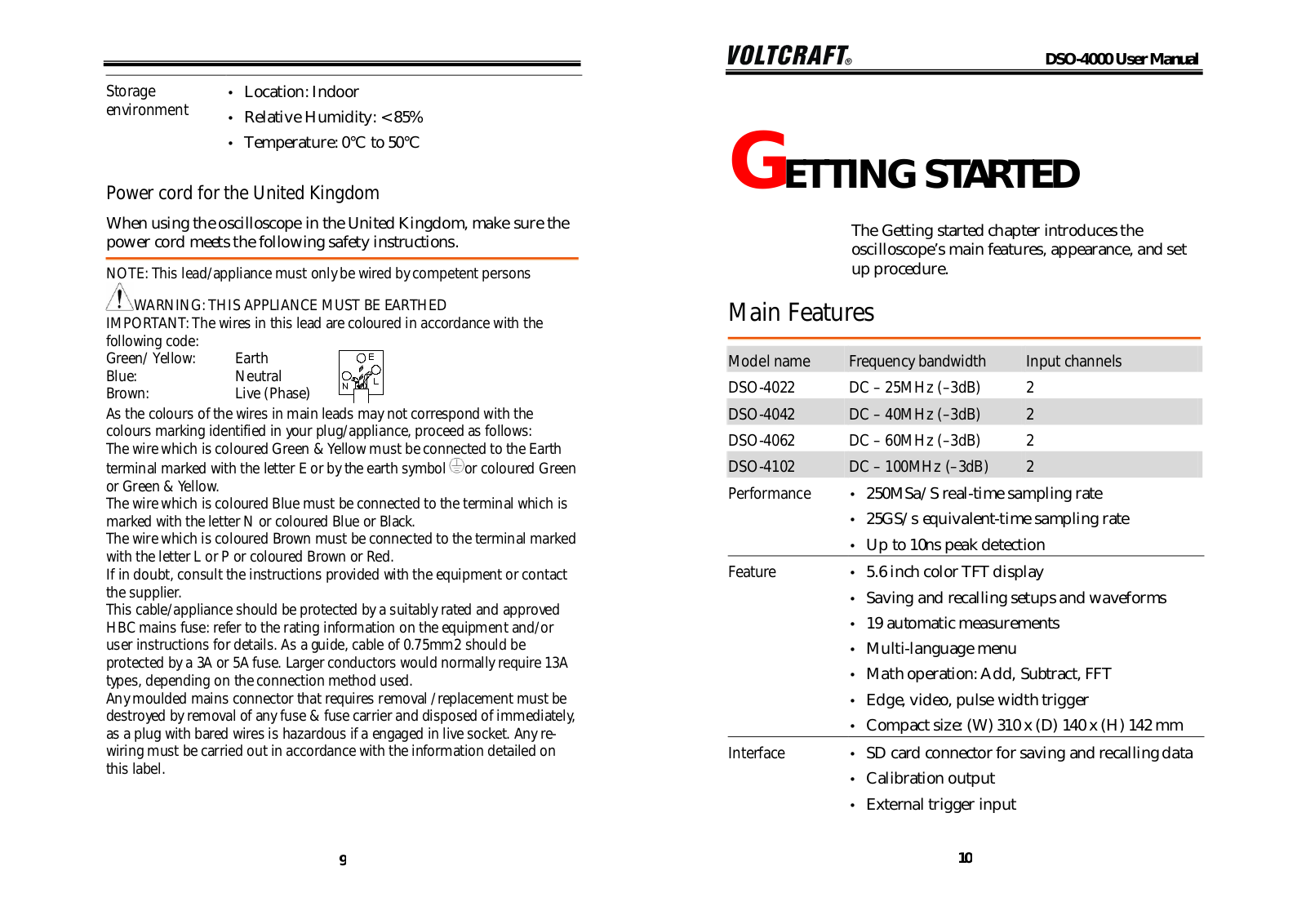
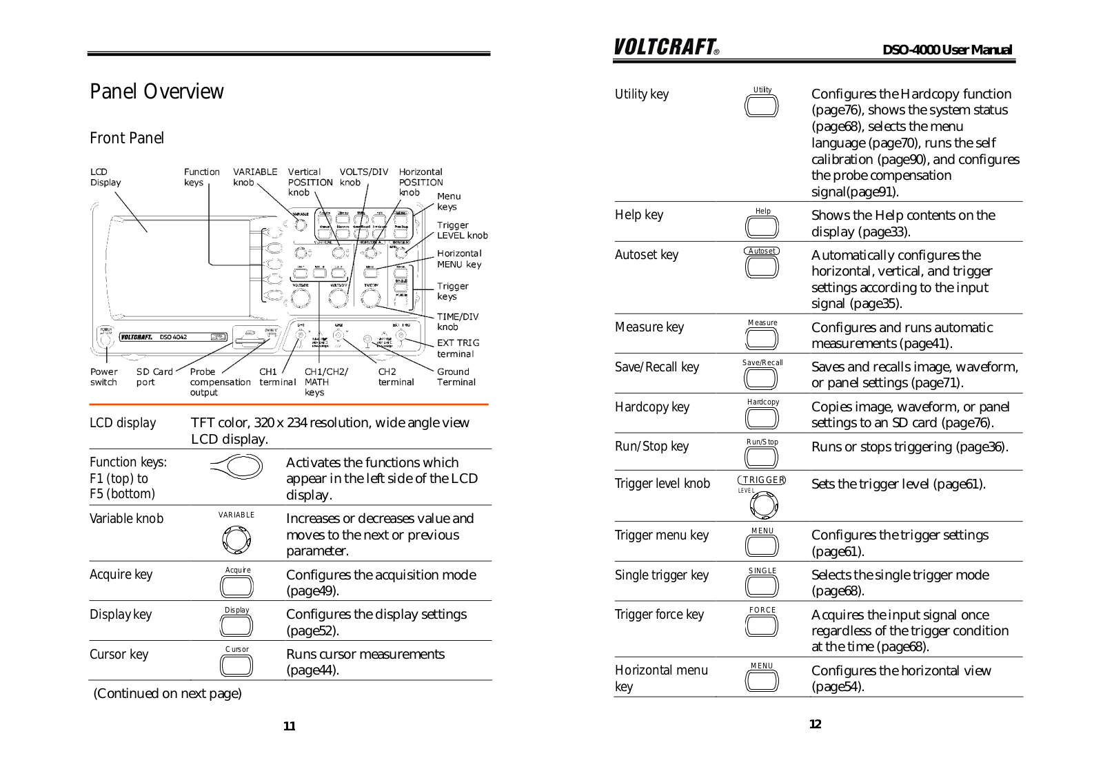
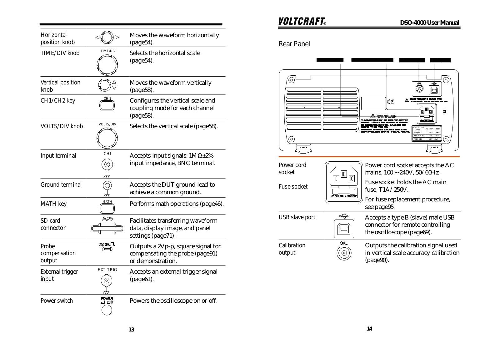
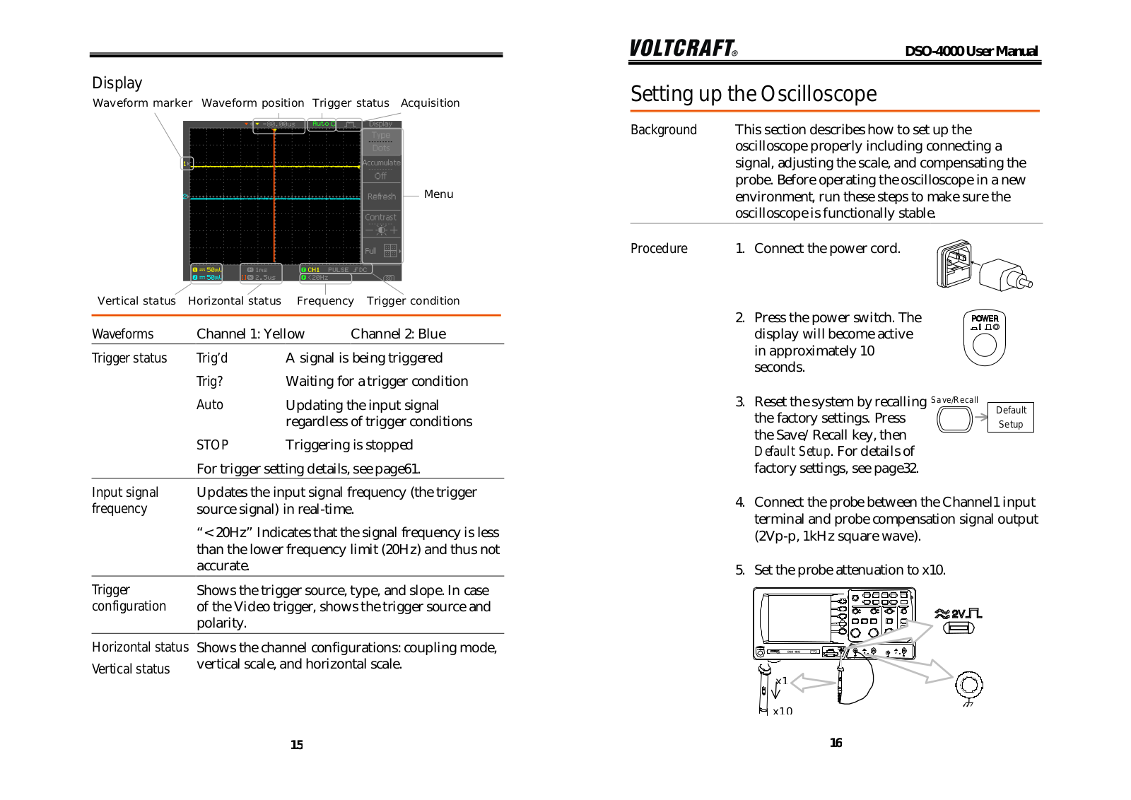
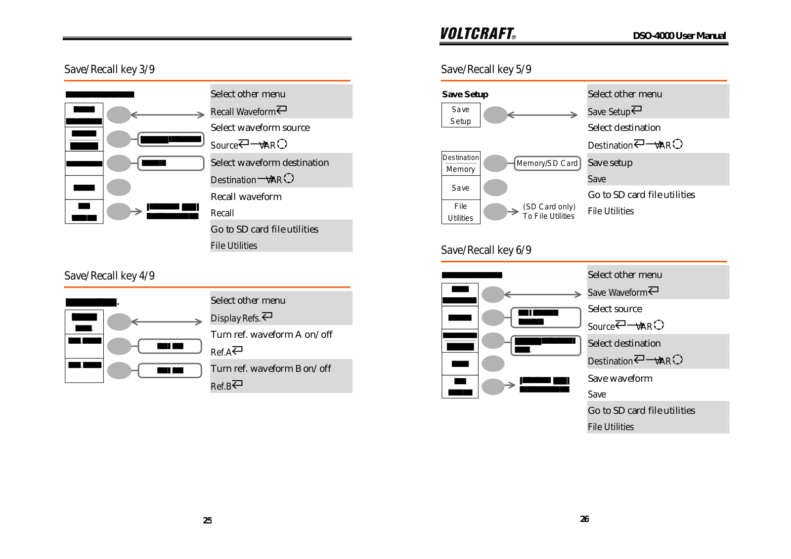
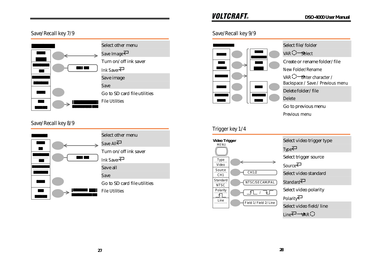
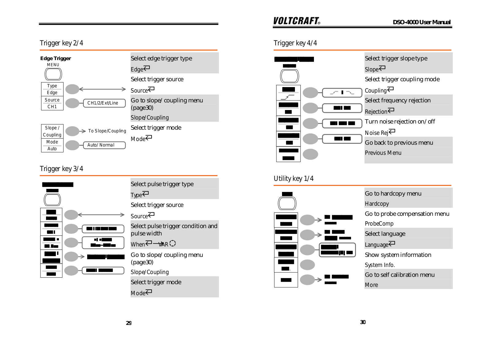
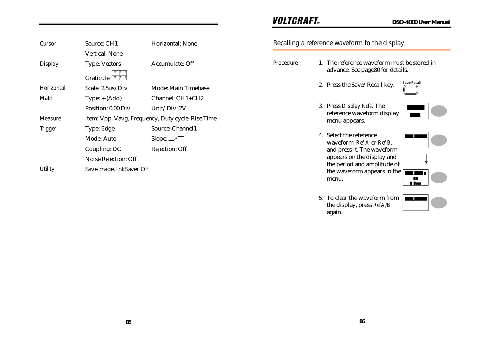
VOLTCRAFT DSO 4022, DSO 4042, DSO 4062, DSO 4102 User guide
...
VOLTCRAFT User guide
Download
Specifications and Main Features
Frequently Asked Questions
User Manual
Download
Loading...
+
hidden pages
Unhide
You need points to download manuals.
1 point = 1 manual.
You can buy points or you can get point for every manual you upload.
Buy points
Upload your manuals
 Loading...