

Page 1

Labor-Netzgerät
BEDIENUNGSANLEITUNG
Seite 3 – 38
Laboratory power supply
OPERATING INSTRUCTIONS
Page 39 – 74
Appareil d’alimentation pour laboratoire
MODE D’EMPLOI
Page 75 – 110
Labvoeding
GEBRUIKSAANWIJZING
Best.-Nr. / Item No. / N° de commande / Bestnr.:
1086555 DPPS-16-30, 1 – 16 V/DC, 0 – 30 A
1086556 DPPS-32-15, 1 – 32 V/DC, 0 – 15 A
1086558 DPPS-60-8, 1 – 60 V/DC, 0 – 8 A
1086559 DPPS-16-40, 1 – 16 V/DC, 0 – 40 A
1086560 DPPS-32-20, 1 – 32 V/DC, 0 – 20 A
1086561 DPPS-60-10, 1 – 60 V/DC, 0 – 10 A
1086562 DPPS-16-60, 1 – 16 V/DC, 0 – 60 A
1086563 DPPS-32-30, 1 – 32 V/DC, 0 – 30 A
1086564 DPPS-60-15, 1 – 60 V/DC, 0 – 15 A
Pagina 111 – 146
Page 2

Page 3

INHALTSVERZEICHNIS
1. Einführung ..............................................................................................................................4
2. Bestimmungsgemäße Verwendung .......................................................................................5
3. Lieferumfang ..........................................................................................................................6
4. Zeichenerklärung ...................................................................................................................7
5. Sicherheitshinweise ...............................................................................................................8
a) Personen / Produkt ...........................................................................................................8
b) Sonstiges ........................................................................................................................10
6. Bedienelemente ...................................................................................................................10
7. Inbetriebnahme ....................................................................................................................12
a) Anschluss des Netzkabels ..............................................................................................12
b) Aufstellen des Gerätes....................................................................................................12
c) Allgemeine Informationen ...............................................................................................12
8. Normalbetrieb .......................................................................................................................14
a) Strombegrenzung einstellen ...........................................................................................14
b) Ausgangsspannung einstellen ........................................................................................15
c) Anschluss eines Verbrauchers........................................................................................16
9. Speicherplatzbetrieb „Preset“ und „Set“ ...............................................................................17
a) Speicherplätze selbst belegen „Set“ .............................................................................18
b) Speicherplätze auf Werkseinstellung zurücksetzen ........................................................18
10. Fernsteuerbetrieb „Remote Ctrl“ ..........................................................................................19
a) Vorbereitung des Fernsteueranschlusses.......................................................................19
b) Steuerung über externe Spannungsquelle .....................................................................20
c) Steuerung über einen regelbaren Widerstand (Poti) ......................................................21
d) Ausgang fernsteuern (Ein/Aus) .......................................................................................22
11. Sense-Funktion (1086562) ...................................................................................................23
12. Software Installieren .............................................................................................................24
13. Steuerung mit PC-Software .................................................................................................24
a) Betriebselemente der Software und Grundbetrieb..........................................................25
b) Interner Voreinstellungsspeicher.....................................................................................27
c) Datenaufzeichnung .........................................................................................................28
d) Einstellungen ..................................................................................................................29
14. Schutzeinrichtungen .............................................................................................................30
a) Überspannungsabschaltung ...........................................................................................30
b) Übertemperaturabschaltung ...........................................................................................30
c) Überlastabschaltung .......................................................................................................31
15. Wartung und Reinigung ........................................................................................................31
a) Netzsicherung wechseln .................................................................................................31
16. Behebung von Störungen ....................................................................................................32
17. Entsorgunga .........................................................................................................................33
18. Technische Daten .................................................................................................................34
19. Zusätzliche Funktionen ........................................................................................................37
a) Manuelle Nullstellung des Geräts ...................................................................................37
b) Rückstellung der Speicherplätze (P1/P2/P3) auf Werkseinstellung ...............................38
3
Page 4

1. EINFÜHRUNG
Sehr geehrte Kundin, sehr geehrter Kunde,
mit dem Kauf eines Voltcraft®-Produktes haben Sie eine sehr gute Entscheidung getroffen, für die
wir Ihnen danken.
Voltcraft® - Dieser Name steht auf dem Gebiet der Mess-, Lade- sowie Netztechnik für
überdurchschnittliche Qualitätsprodukte, die sich durch fachliche Kompetenz, außergewöhnliche
Leistungsfähigkeit und permanente Innovation auszeichnen.
Vom ambitionierten Hobby-Elektroniker bis hin zum professionellen Anwender haben Sie mit einem
Produkt der Voltcraft® - Markenfamilie selbst für die anspruchsvollsten Aufgaben immer die optimale
Lösung zur Hand. Und das Besondere: Die ausgereifte Technik und die zuverlässige Qualität unserer
Voltcraft® - Produkte bieten wir Ihnen mit einem fast unschlagbar günstigen Preis-/Leistungsverhältnis
an. Darum schaffen wir die Basis für eine lange, gute und auch erfolgreiche Zusammenarbeit.
Wir wünschen Ihnen nun viel Spaß mit Ihrem neuen Voltcraft® - Produkt!
Alle enthaltenen Firmennamen und Produktbezeichnungen sind Warenzeichen der jeweiligen
Inhaber. Alle Rechte vorbehalten.
Bei technischen Fragen wenden Sie sich bitte an:
Deutschland: www.conrad.de
Österreich: www.conrad.at
Schweiz: www.conrad.ch
4
Page 5
2. BESTIMMUNGSGEMÄSSE VERWENDUNG
Das Labornetzgerät dient als potentialfreie DC-Spannungsquelle zum Betrieb von
Kleinspannungsverbrauchern. Der einstellbare Ausgang kann an der Vorderseite bis max. 5 A und
an der Rückseite bis zur vollen Nennstromstärke abgegriffen werden. Der vordere Ausgang ist auf
5 A begrenzt und gegen Überlastung geschützt. Bei der Reihenschaltung der Ausgänge mehrerer
Netzgeräte können berührungsgefährliche Spannungen >75 V/DC erzeugt werden. Ab dieser
Spannung müssen aus Sicherheitsgründen schutzisolierte Leitungen/Messkabel zum Einsatz
kommen. Der Anschluss erfolgt an der Vorderseite über 4 mm Sicherheits-Buchsen, an der Rückseite
über Hochstrom-Schraubklemmbuchsen. Die Ausgänge (vorne und hinten) sind miteinander
verbunden.
Es müssen ausreichend dimensionierte Anschlusskabel verwendet werden. Ein zu
geringer Leiterquerschnitt kann zur Überhitzung und zum Brand führen.
Die Ausgangsdaten der Labornetzgeräte sind wie folgt:
Typ Ausgangsspannung Ausgangsstrom (Insgesamt, MAIN + AUX)
DPPS-16-30 1 – 16 V/DC 0 – 30 A
DPPS-32-15 1 – 32 V/DC 0 – 15 A
DPPS-60-8 1 – 60 V/DC 0 – 8 A
DPPS-16-40 1 – 16 V/DC 0 – 40 A
DPPS-32-20 1 – 32 V/DC 0 – 20 A
DPPS-60-10 1 – 60 V/DC 0 – 10 A
DPPS-16-60 1 – 16 V/DC 0 – 60 A
DPPS-32-30 1 – 32 V/DC 0 – 30 A
DPPS-60-15 1 – 60 V/DC 0 – 15 A
Die Einstellung für Spannung und Strom erfolgt stufenlos über digitale Drehregler mit Grob- und
Feineinstellung, um eine schnelle und präzise Werteinstellung zu ermöglichen. Die Werte werden im
übersichtlichen Display angezeigt. Die Strombegrenzung für den Konstantstrombetrieb kann ohne
Kurzschlussbrücke voreingestellt werden.
Das Netzgerät ist fernsteuerbar. Über eine externe Spannung (0 - 5 V/DC) oder über ein externes
Potentiometer (5 kOhm) kann die Ausgangsspannung und der Ausgangsstrom eingestellt werden.
Der DC-Ausgang ist über einen Schaltkontakt ein- und ausschaltbar.
Drei frei programmierbare Speicherplätze können mit unterschiedlichen Festspannungen und
Strombegrenzungen belegt werden. Der Wahlschalter bendet sich an der Rückseite.
5
Page 6
Mit der im Lieferumfang enthaltenen Software und dem USB-Anschluss kann die Stromversorgung
zum Betrieb von zyklischen Arbeitsabläufen über einen PC gesteuert werden. Bis zu 20
programmierbare Spannungs- und Strom-Sets mit unterschiedlicher Zeitdauer können für den Betrieb
programmiert werden. Die zyklischen Arbeitsabläufe können bis zu 999-mal wiederholt werden.
Das Gerät ist überlast- und kurzschlussfest und beinhaltet eine Sicherheits-Temperaturabschaltung.
Das Labornetzgerät ist in Schutzklasse 1 aufgebaut. Es ist nur für den Anschluss an
Schutzkontaktsteckdosen mit Schutzerdung und einer haushaltsüblichen Wechselspannung von
230 V/AC zugelassen.
Aus Sicherheits- und Zulassungsgründen (CE) ist das eigenmächtige Umbauen und/oder Verändern
des Produktes nicht gestattet. Eine andere Verwendung als oben beschrieben ist nicht erlaubt
und kann zur Beschädigung des Produkts führen. Darüber hinaus ist dies mit Gefahren, wie z. B.
Kurzschluss, Brand, Stromschlag usw. verbunden. Lesen Sie die Bedienungsanleitung genau durch
und bewahren Sie diese für späteres Nachschlagen auf.
Befolgen Sie alle Sicherheitshinweise und Informationen in dieser Anleitung.
3. LIEFERUMFANG
• Labor-Netzgerät
• Remote-Anschlussbuchse
• Schutzkontakt-Netzkabel
• USB-Kabel
• CD (Software)
• Bedienungsanleitung
Aktuelle Bedienungsanleitungen
Laden Sie aktuelle Bedienungsanleitungen über den Link www.conrad.com/downloads herunter oder
scannen Sie den abgebildeten QR-Code. Befolgen Sie die Anweisungen auf der Webseite.
6
Page 7
4. ZEICHENERKLÄRUNG
Ein Ausrufungszeichen in einem Dreieck zeigt wichtige Anweisungen in dieser Anleitung,
die unbedingt befolgt werden müssen.
Ein Blitzsymbol im Dreieck warnt vor einem elektrischen Schlag oder der Beeinträchtigung
der elektrischen Sicherheit des Geräts.
Dieses Symbol zeigt Tipps und Informationen zur Bedienung.
Nur zur Verwendung in trockenen Innenbereichen.
Dieses Gerät ist CE-konform und erfüllt die erforderlichen nationalen und europäischen
Richtlinien.
Schutzleiteranschluss; diese Schraube darf nicht gelöst werden.
7
Page 8

5. SICHERHEITSHINWEISE
Lesen Sie sich die Bedienungsanleitung aufmerksam durch und beachten Sie
insbesondere die Sicherheitshinweise. Falls Sie die Sicherheitshinweise und die
Angaben zur sachgemäßen Handhabung in dieser Bedienungsanleitung nicht
befolgen, übernehmen wir für dadurch resultierende Personen-/Sachschäden keine
Haftung. Außerdem erlischt in solchen Fällen die Gewährleistung/Garantie.
a) Personen / Produkt
• Das Produkt ist kein Spielzeug. Halten Sie es von Kindern und Haustieren fern.
• Lassen Sie das Verpackungsmaterial nicht achtlos liegen. Dieses könnte für Kinder zu
einem gefährlichen Spielzeug werden.
• Schützen Sie das Produkt vor extremen Temperaturen, direktem Sonnenlicht, starken
Erschütterungen, hoher Feuchtigkeit, Nässe, brennbaren Gasen, Dämpfen und
Lösungsmitteln.
• Setzen Sie das Produkt keiner mechanischen Beanspruchung aus.
• Wenn kein sicherer Betrieb mehr möglich ist, nehmen Sie das Produkt außer Betrieb
und schützen Sie es vor unbeabsichtigter Verwendung. Der sichere Betrieb ist nicht
mehr gewährleistet, wenn das Produkt:
- sichtbare Schäden aufweist,
- nicht mehr ordnungsgemäß funktioniert,
- über einen längeren Zeitraum unter ungünstigen Umgebungsbedingungen gelagert
wurde oder
- erheblichen Transportbelastungen ausgesetzt wurde.
• Gehen Sie vorsichtig mit dem Produkt um. Durch Stöße, Schläge oder dem Fall aus
bereits geringer Höhe wird es beschädigt.
• Beachten Sie auch die Sicherheitshinweise und Bedienungsanleitungen der übrigen
Geräte, an die das Produkt angeschlossen wird.
• Produkte, die an Netzspannung betrieben werden, gehören nicht in Kinderhände.
Lassen Sie deshalb beim Betrieb des Produkts in Anwesenheit von Kindern
besondere Vorsicht walten, insbesondere wenn diese versuchen, Gegenstände
durch Gehäuseöffnungen in ein Gerät zu stecken. Es besteht die Gefahr eines
lebensgefährlichen elektrischen Schlags.
• Gießen Sie nie Flüssigkeiten über elektrischen Geräten aus und stellen Sie keine
mit Flüssigkeit gefüllten Gegenstände (z.B. Vasen) darauf ab bzw. in deren Nähe. Es
besteht höchste Gefahr eines Brandes oder lebensgefährlichen elektrischen Schlags.
• Betreiben Sie das Produkt nur in trockenen Innenräumen. Es darf nicht feucht oder
nass werden. Ansonsten besteht Lebensgefahr durch einen elektrischen Schlag!
• In Schulen, Ausbildungsstätten, Hobby- und Selbsthilfewerkstätten muss der Umgang
mit elektrischen Geräten durch geschultes Personal überwacht werden.
• Beachten Sie in gewerblichen Einrichtungen die Unfallverhütungsvorschriften des
Verbandes der gewerblichen Berufsgenossenschaften für elektrische Anlagen und
Betriebsmittel.
8
Page 9

• Beim Öffnen von Abdeckungen oder Entfernen von Teilen können spannungsführende
Teile freigelegt werden.Trennen Sie deshalb vor einer Wartung oder Instandsetzung
das Produkt von allen Spannungsquellen. Kondensatoren im Gerät können noch
geladen sein, selbst wenn es von allen Spannungsquellen getrennt wurde.
• Verlegen Sie Kabel immer so, dass niemand über diese stolpern oder an ihnen hängen
bleiben kann. Es besteht Verletzungsgefahr.
• Tragen Sie während der Arbeit mit Netzteilen oder Ladegeräten keine metallenen
und leitenden Schmuckketten, Armreifen, Ringe usw. Verbinden Sie Netzteile und
Ladegeräte unter keinen Umständen mit Menschen oder Tieren.
• Überprüfen Sie vor jedem Einsatz das Produkt auf Beschädigung(en). Falls Sie
Beschädigungen feststellen, verwenden Sie das Produkt nicht mehr. Trennen Sie es
von der Netzspannung und ziehen Sie das Steckernetzteil aus der Netzsteckdose.
Bringen Sie das Produkt danach in eine Fachwerkstatt.
• Verwenden Sie als Spannungsquelle ausschließlich eine ordnungsgemäße
Netzsteckdose (230V~/50Hz) des öffentlichen Versorgungsnetzes.
• Die Netzsteckdose muss sich in der Nähe des Geräts benden und leicht zugänglich sein.
• Sollte die Netzleitung Beschädigungen aufweisen, so berühren Sie sie nicht. Schalten
Sie zuerst die zugehörige Netzsteckdose stromlos (z.B. über den zugehörigen
Sicherungsautomaten) und ziehen Sie danach den Netzstecker vorsichtig aus der
Netzsteckdose. Betreiben Sie das Produkt auf keinen Fall mit beschädigter Netzleitung.
• Ein beschädigtes Netzkabel darf nur vom Hersteller, einer von ihm beauftragten
Werkstatt oder einer ähnlich qualizierten Person ersetzt werden, um Gefährdungen
zu vermeiden.
• Netzstecker dürfen nie mit nassen Händen ein- oder ausgesteckt werden.
• Ziehen Sie das Steckernetzteil nicht am Kabel aus der Netzsteckdose!
• Unter folgenden Bedingungen muss der Netzstecker aus der Steckdose gezogen
werden:
- vor dem Reinigen des Produkts
- bei Gewitter
- wenn das Produkt über einen längeren Zeitraum nicht verwendet wird.
• Achten Sie während des Betriebs auf eine ausreichende Belüftung des Produkts.
Decken Sie die Belüftungsöffnungen nicht durch Zeitschriften, Decken, Vorhänge o.ä.
ab. Halten Sie einen Mindestabstand von 15 cm zu anderen Gegenständen ein.
• Stellen Sie sicher, dass beim Aufstellen die Kabel nicht gequetscht, geknickt oder
durch scharfe Kanten beschädigt werden.
• Es dürfen sich keine Geräte mit starken elektrischen oder magnetischen Feldern, wie
z.B. Transformatoren, Motoren, schnurlose Telefone, Funkgeräte usw. in direkter Nähe
zum Produkt benden, da diese das Produkt beeinussen können.
9
Page 10

• Betreiben Sie das Produkt nicht an Orten oder in Räumen, die ungünstige
Umgebungsbedingungen aufweisen. Dies kann zur Beschädigung der empndlichen
Elektronik im Inneren des Produkts führen und ist mit lebensbedrohenden Gefahren
verbunden. Ungünstige Umgebungsbedingungen sind:
- Hohe Luftfeuchtigkeit (> 80 % relativ, Kondensation)
- Feuchtigkeit, Staub, brennbare Gase, Lösungsmitteldämpfe, Benzin
- Hohe Umgebungstemperatur (> ca. +50 °C)
- Elektromagnetische Felder (Motoren, Transformatoren, Audiosysteme für
Modellbau usw.) oder elektrostatische Felder
• Das Gerät sollte nicht sofort nach einem Wechsel von kalter zu warmer Umgebung
angeschlossen werden. Kondenswasser könnte zu Schäden am Gerät führen. Warten
Sie, bis sich das Gerät der neuen Umgebungstemperatur angepasst hat.
b) Sonstiges
• Wenden Sie sich an eine Fachkraft, wenn Sie Zweifel über die Arbeitsweise, die
Sicherheit oder den Anschluss des Produktes haben.
• Lassen Sie Wartungs-, Anpassungs- und Reparaturarbeiten ausschließlich von einem
Fachmann bzw. einer Fachwerkstatt durchführen.
• Sollten Sie noch Fragen haben, die in dieser Bedienungsanleitung nicht beantwortet
werden, wenden Sie sich an unseren technischen Kundendienst oder an andere
Fachleute.
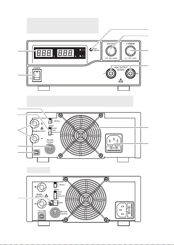
6. BEDIENELEMENTE
1. LED-Messanzeigeelement mit Anzeige für C.V. (Konstantspannung) und C.C. (Konstantstrom)
2. Kontrollanzeige REAR CONTROL (Steuerung über Geräterückseite)
3. Einstellregler VOLTAGE (Ausgangsspannung)
4. Einstellregler CURRENT (Ausgangsstrom)
5. Ein-/Ausschalter POWER (ein/aus)
6. Anschlussbuchsen AUX. OUTPUT 5A MAX. (AUX.-Ausgangsanschlüsse)
7. Anschlussbuchsen MAIN OUTPUT(Ausgangsanschlüsse)
8. Wahlschalter MODE (Modus wählen)
9. Wahlschalter RECALL (Abruf)
10. Fernsteuerungsanschluss Remote Control
11. Schutzgitter Kühlgebläse
12. Kaltgeräteanschluss und Netzsicherung
13. USB-Buchse
14. Anschlussbuchsen SENSE (Sensor-Anschlüsse)
10
Page 11
1086555 / 1086556 / 1086558 1086559 /
1086560 / 1086561 / 1086562 /
1086563 / 1086564
2
3
1
5
1086555 / 1086556 / 1086558 1086559 / 1086560 / 1086561
1086563 / 1086564
9
8
7
10
13
1086562
14
4
6
11
12
11
Page 12

7. INBETRIEBNAHME
Das Labornetzgerät ist kein Ladegerät. Verwenden Sie zum Laden von Akkus
geeignete Ladegeräte mit entsprechender Ladeabschaltung.
Bei längerem Betrieb mit Nennlast wird die Gehäuseoberäche warm. Achtung!
Mögliche Verbrennungsgefahr ! Achten Sie daher unbedingt auf eine ausreichende
Belüftung des Netzgerätes und betreiben Sie es niemals teilweise oder ganz
abgedeckt, um eventuelle Schäden zu vermeiden.
Achten Sie beim Anschluss eines Verbrauchers unbedingt darauf, dass dieser im
nicht eingeschalteten Zustand angeschlossen wird. Ein eingeschalteter Verbraucher
kann beim Anschluss an die Ausgangsbuchsen des Netzgerätes zu einer
Funkenbildung führen, welche wiederum die Buchsen bzw. die angeschlossenen
Leitungen und/oder deren Klemmen beschädigen können.
Wenn Sie Ihr Netzgerät nicht benötigen, schalten Sie es aus und trennen es vom
Netz. Die Anzeigen bleiben nach dem Ausschalten noch einige Sekunden an, um
die internen Kondensatoren zu entladen und die zuletzt eingestellten Parameter
abzuspeichern.
Auf einen ausreichenden Leiterquerschnitt der DC-Anschlussleitungen ist
unbedingt zu achten, da eine Überlastung zum Leitungsbrand führen kann.
a) Anschluss des Netzkabels
1. Verbinden Sie das beiliegende Schutzkontakt-Netzkabel mit dem Kaltgeräteanschluss (12) am
Netzgerät. Achten Sie auf festen Sitz.
2. Verbinden Sie das Netzkabel mit einer Schutzkontakt-Steckdose mit Schutzerdung. Die
Gesamtlänge des Netzkabels bis zur Steckdose darf 3 m nicht überschreiten.
b) Aufstellen des Gerätes
Stellen Sie das Labornetzgerät auf eine stabile, ebene und unempndliche Oberäche ab. Achten Sie
darauf, dass die Lüftungsschlitze im Gehäuse nicht verdeckt werden.
c) Allgemeine Informationen
Das Labornetzgerät ist mikroprozessorgesteuert und wird über zwei digitale Einstellregler
(Inkrementalgeber ohne Endposition) mit Tastfunktion bedient. Dies ermöglicht die Fein- und
Grobregelung über einen Regler.
12
Page 13
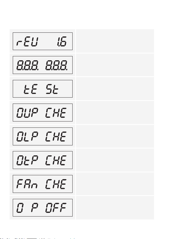
Nach dem Einschalten erfolgt ein Systemcheck. In den beiden Anzeigen wird der Teststatus
angezeigt. Die Anzeigereihenfolge ist wie folgt:
Anzeige des aktuellen Softwarestandes.
Segmenttest ob die Anzeige mit allen Einzelsegmenten funktioniert.
Danach erfolgt der Test der LED-Anzeigen C.V.,
C.C. und REAR CONTROL.
Systemtest der Schutzvorrichtungen beginnt.
Der Überspannungsschutz wird geprüft.
Der Überlastschutz wird geprüft.
Der Übertemperaturschutz wird geprüft.
Lüftertest. Der Lüfter wird kurz über den gesamten
Drehzahlbereich getestet. Die Lüfterdrehzahl nimmt
kurz hörbar zu.
Die Fernsteuerfunktion für „Ausgang aus“ wird
geprüft. Nach diesem Schritt wird in die normale
Betriebsanzeige umgeschaltet.
13
Page 14
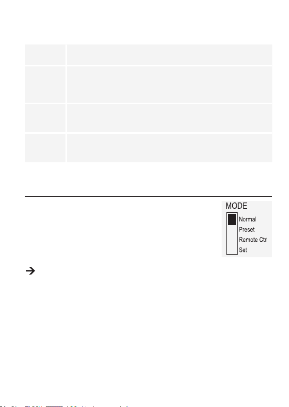
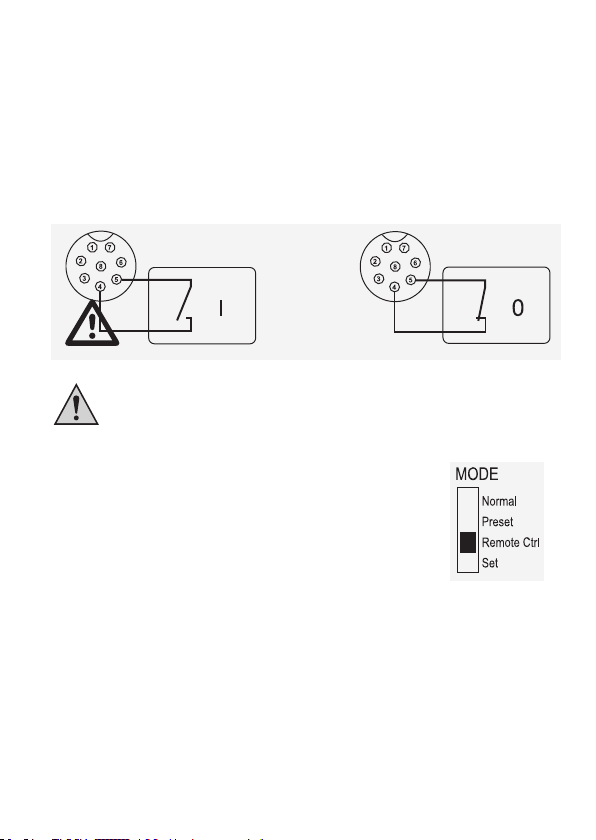
Das Netzgerät ermöglicht den Betrieb in 4 Modi. Diese Modi werden über den Wahlschalter MODE (8)
an der Rückseite angewählt. Folgende Modi sind möglich:
Normal Normalbetrieb. Die Einstellung von Spannung und Strom erfolgt an der
Preset Speicherplatzbetrieb. Im Gerät können drei Festspannungen eingespeichert
Remote Ctrl Fernsteuerbetrieb. Das Netzgerät kann über eine externe Spannung oder ein
Set Einstellbetrieb. Die drei Preset-Plätze können frei programmiert werden.
Die einzelnen Betriebsmodi werden Ihnen im folgenden genauer beschrieben.
Vorderseite.
und über diese Preset-Funktion direkt angewählt werden. Die Wahl des
Speicherplatzes erfolgt über den Wahlschalter RECALL (9). Die vorderen
Einstellregler sind inaktiv.
externes Poti ferngesteuert werden. Die Ferneinstellung kann für Spannung und
Strom erfolgen. Die vorderen Einstellregler sind inaktiv.
Speicherplatz am Schiebeschalter Wahlschalter RECALL (9) wählen und
Einstellungen über Einstellregler (3, 4) vornehmen.
8. NORMALBETRIEB
Im Normalbetrieb lässt sich das Netzgerät über die vorderen Einstellregler
bedienen. Achten Sie darauf, dass sich der Wahlschalter MODE in Position
Normal bendet. Entfernen Sie angeschlossene Verbraucher vom Ausgang
(6 oder 7).
Schalten Sie das Netzgerät über den Ein-/Ausschalter POWER (5) ein.
Die Anzeige (1) leuchtet und nach einem kurzen Selbsttest erscheint die
Spannungs- und Stromanzeige.
Stellen Sie vor jeder Spannungseinstellung erst die Strombegrenzung ein. Ein zu hoher
Stromwert kann Ihre Anschlussleitungen beschädigen, ein zu niedriger Stromwert (<1 A) kann
die Ausgangsspannung begrenzen.
a) Strombegrenzung einstellen
Die Begrenzung des Ausgangsstromes ist ein Schutzmechanismus, um den Verbraucher oder
die Anschlussleitungen zu schützen. Die Strombegrenzung kann ohne Kurzschluss am Ausgang
voreingestellt werden. Das Netzgerät liefert dann maximal den voreingestellten Strom.
1. Entfernen Sie angeschlossene Verbraucher vom Netzgerät.
2. Schalten Sie das Netzgerät über den Ein-/Ausschalter POWER (5) ein. Die Anzeige (1) leuchtet
und nach einem kurzen Selbsttest erscheint die Spannungs- und Stromanzeige.
3. Stellen Sie die Strombegrenzung am Einstellregler CURRENT (4) entsprechend Ihrer Anwendung
ein.
4. Drehen Sie am Regler und es erscheint der Strombegrenzungswert.
14
Page 15
Erfolgt innerhalb von 2 Sekunden keine Einstellung, schaltet die Anzeige wieder zur
aktuellen Stromanzeige zurück.
5. Zum Einstellen der Strombegrenzung drehen Sie den Einstellregler nach links oder rechts. Nach
dem Einschalten ist immer der Fein-Einstellbereich (0,1 A) aktiv. Dies wird durch eine leicht hellere
Ziffer dargestellt. Drücken Sie kurz auf den Einstellregler. Die Dezimalstelle (1,0 oder 0,1) des
Einstellbereichs ändert sich bei jedem Drücken. Drehen verändert den Wert.
6. Die Einstellung kann grob (im Einerstellenbereich) oder fein (im Zehntelbereich) erfolgen.
7. Wurde der gewünschte Stromwert eingestellt, schaltet die Anzeige nach ca. 2 Sekunden
automatisch in die normale Anzeige zurück.
Wird die voreingestellte Stromstärke im Normalbetrieb erreicht, schaltet das Netzgerät in den
Strombegrenzungsmodus und reduziert dabei den Spannungswert. Dieser Betrieb wird mit der
roten Statusanzeige C.C. (1) signalisiert.
b) Ausgangsspannung einstellen
Die Ausgangsspannung kann am Einstellregler VOLTAGE (3) eingestellt werden. Die Grob- und
Feinregelung erfolgt in gleicher Weise wie bei der Einstellung der Strombegrenzung.
Durch den großen Regelbereich kann es sein, dass die Spannungseinstellung ca.
1-2 Sekunden benötigt, um von einem hohen auf einen niedrigeren Spannungswert
zu regeln.
Im normalen Betrieb arbeitet das Gerät im Konstantspannungsmodus. Das heißt, das
Netzgerät gibt eine konstante voreingestellte Ausgangsspannung ab. Dieser Betrieb wird mit
der grünen Statusanzeige C.V. (1) signalisiert.
15
Page 16

c) Anschluss eines Verbrauchers
Achten Sie beim Anschluss eines Verbrauchers darauf, dass dieser ausgeschaltet
mit dem Netzgerät verbunden wird. Die max. Stromaufnahme des anzuschließenden
Verbrauchers darf die Angaben in den technischen Daten nicht überschreiten.
Bei der Reihenschaltung der Ausgänge mehrerer Netzgeräte können
berührungsgefährliche Spannungen (> 75 VDC) erzeugt werden, welche
bei Berührung lebensgefährlich sein können. Ab dieser Spannung darf nur
schutzisoliertes Zubehör (Anschlussleitungen, Messleitungen etc.) verwendet
werden. Die Verwendung metallisch blanker Leitungen und Kontakte ist zu
vermeiden. Alle diese blanken Stellen sind durch geeignete, schwer entammbare
Isolierstoffe oder andere Maßnahmen abzudecken und vor direkter Berührung und
Kurzschluss zu schützen.
Achten Sie auf einen ausreichenden Leiterquerschnitt für die vorgesehene
Stromstärke.
Am Netzgerät sind zwei Ausgänge vorhanden. Diese Ausgänge führen immer die selbe
Ausgangsspannung. Der Unterschied liegt jedoch in der Strombelastbarkeit.
An den Anschlussbuchsen AUX. OUTPUT 5A MAX. (6) dürfen max. 5 A abgegriffen
werden. Ein PTC-Überlastschutz schützt diese Anschlüsse vor Überlast und
unterbricht im Fall von Aktivierung (>5 A) die Stromzufuhr. Um das Gerät
zurückzustellen, schalten Sie es umgehend aus und lassen Sie es vor der nächsten
Nutzung auf Raumtemperatur abkühlen.
Die rückseitigen Anschlussbuchsen MAIN OUTPUT (Schraub-Buchsen) (7)
sind für den vollen Nennstrom ausgelegt. Ab 5 A Ausgangsstrom wird die
Schraubklemmfunktion der rückseitigen Buchsen empfohlen, um eine Überhitzung
der Steck-Buchsen zu vermeiden.
1. Entfernen Sie angeschlossene Verbraucher vom Ausgang.
2. Schalten Sie das Netzgerät über den Ein-/Ausschalter POWER (5) ein. Die Betriebsanzeige (1)
leuchtet und in der Anzeige erscheint die Spannungs- und Stromanzeige.
3. Stellen Sie die Parameter nach Ihren Vorgaben wie im Kapitel „Inbetriebnahme“ beschrieben ein.
4. Kontrollieren Sie nochmals die korrekt eingestellte Ausgangsspannung.
5. Verbinden Sie den Pluspol (+) des Verbrauchers mit der roten Buchse „+“ und den Minuspol (-) mit
der schwarzen Buchse „-“ des entsprechenden Ausgangs (vorne = AUX. OUTPUT 5A MAX. (6),
hinten = MAIN OUTPUT (7)).
16
Page 17
Der angeschlossene Verbraucher kann jetzt eingeschaltet werden.
Die Stromaufnahme des angeschlossenen Verbrauchers wird in der Anzeige (1) in Ampere (A)
angezeigt.
9. SPEICHERPLATZBETRIEB „PRESET“ UND „SET“
Im Gerät können drei Festspannungen inkl. Stromeinstellungen über die Set-Funktion eingespeichert
und über die Preset-Funktion direkt angewählt werden.
Werkseitig sind alle drei Speicherplätze (P1, P2, P3) voreingestellt.
Diese sind wie folgt belegt:
Speicher
Typ
DPPS-16-30 5 V Maximum 13.8 V Maximum 15 V Maximum
DPPS-32-15 5 V Maximum 13.8 V Maximum 25 V Maximum
DPPS-60-8 5 V Maximum 13.8 V Maximum 55 V Maximum
DPPS-16-40 5 V Maximum 13.8 V Maximum 15 V Maximum
DPPS-32-20 5 V Maximum 13.8 V Maximum 25 V Maximum
DPPS-60-10 5 V Maximum 13.8 V Maximum 55 V Maximum
DPPS-16-60 5 V Maximum 13.8 V Maximum 15 V Maximum
DPPS-32-30 5 V Maximum 13.8 V Maximum 25 V Maximum
DPPS-60-15 5 V Maximum 13.8 V Maximum 55 V Maximum
Achten Sie darauf, dass keine Verbraucher angeschlossen sind.
Der Datenspeicher kann über die mitgelieferte Software eingestellt werden. Beachten Sie
hierzu das Kapitel “Steuerung mit PC-Software”.
P1 P2 P3
Spannung Strom Spannung Strom Spannung Strom
17
Page 18
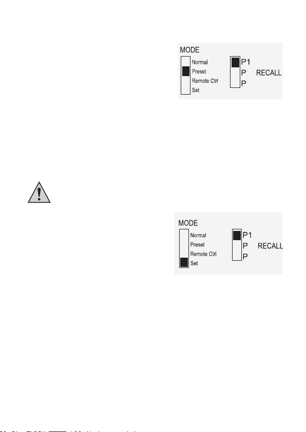
1. Aktivieren Sie die Preset-Funktion über den rückseitigen Wahlschalter MODE (8).
2. Stellen Sie den Schalter in Position Preset. Die
vorderseitige Kontrollanzeige REAR CONTROL (2)
leuchtet. Die vorderen Einstellregler sind jetzt inaktiv.
3. Wählen Sie am rückseitigen Wahlschalter
RECALL (9) den entsprechenden Speicherplatz P1,
P2 oder P3. Die entsprechende Ausgangsspannung
wird in der Anzeige (1) angezeigt.
4. Der Verbraucher kann angeschlossen und
eingeschaltet werden.
5. Zum Deaktivieren der Festspannungsfunktion schieben sie den Wahlschalter MODE (8) zurück
in Position Normal. Die Kontrollanzeige REAR CONTROL (2) erlischt. Es wird in den normalen
Netzgerätebetrieb umgeschaltet (DC-Verbraucher immer vorher entfernen!)
2
3
a) Speicherplätze selbst belegen „Set“
Alle drei Speicherplätze können mit benutzereigenen Werten für Ausgangsspannung und
Strombegrenzung belegt werden.
Achten Sie darauf, dass keine Verbraucher angeschlossen sind.
1. Aktivieren Sie die Set-Funktion über den
rückseitigen Wahlschalter MODE (8). Stellen Sie
den Schalter in Position Set. Die vorderseitige
Kontrollanzeige REAR CONTROL (2) leuchtet.
Wählen Sie am rückseitigen Wahlschalter
RECALL (9) den entsprechenden Speicherplatz
P1, P2 oder P3. Die entsprechenden Werte für
Spannung und Strom werden in der Anzeige (1)
angezeigt.
2. Über die vorderseitigen Einstellregler (3 und 4) kann die gewünschte Ausgangsspannung und die
Strombegrenzung eingestellt werden.
3. Wiederholen Sie diese Schritte bei Bedarf mit den anderen Speicherplätzen.
4. Sind alle Parameter eingestellt, schieben sie den Wahlschalter MODE (8) zurück in Position
Preset für den Festspannungsbetrieb oder Position Normal für den Standard-Betrieb.
2
3
b) Speicherplätze auf Werkseinstellung zurücksetzen
1. Schalten Sie das Netzgerät aus.
2. Drücken Sie von vorne gleichzeitig auf die beiden Drehregler und halten diese gedrückt.
3. Schalten Sie das Netzgerät ein. Nachdem die Anzeigen aueuchten lassen Sie die beiden
Drehregler los. Die werksseitig voreingestellten Parameter sind wieder vorhanden.
18
Page 19
10. FERNSTEUERBETRIEB „REMOTE CTRL“
Über den eingebauten Fernsteuerungsanschluss Remote Control (10) kann die Spannungs- und
Stromeinstellung mit einer externen Spannungsquelle oder über einen externen, einstellbaren
Widerstand (kurz „Poti“) erfolgen. Der Fernsteuerungsanschluss erfolgt am rückseitigen
Fernsteuerungsanschluss Remote Control (10). Für den Anschluss liegt eine RemoteAnschlussbuchse bei.
Im Fernsteuerbetrieb muss immer der Stromsteuerpfad mit angeschlossen sein,
da der Ausgang sonst in den Strombegrenzungsmodus „C.C.“ schaltet und die
Ausgangsspannung begrenzt.
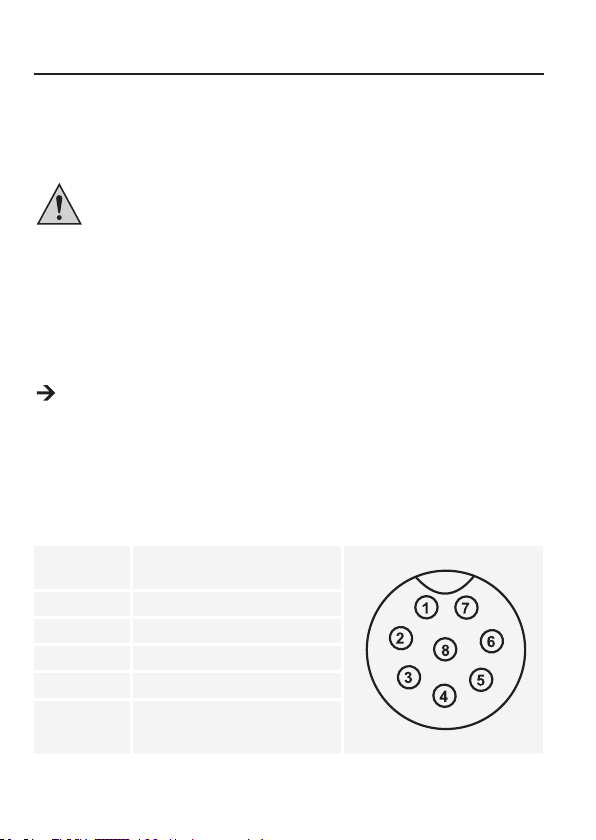
a) Vorbereitung des Fernsteueranschlusses
1. Lösen Sie die seitliche Schraube der beiliegenden Remote-Anschlussbuchse und nehmen mit
einer kleinen Drehbewegung die vordere, schwarze Kontaktbuchse heraus.
2. Führen Sie von hinten durch die Metallhülse fünf Anschlussleitungen mit einem Leiterquerschnitt
von mindestens 0,34 mm2. Löten Sie diese Leitungen an den Lötfahnen Nr. 1, 2, 3, 4 und 5 der
schwarzen Kontaktbuchse sorgfältig fest. Achten Sie darauf, dass keine Kurzschlüsse entstehen.
Die Ziffern der Lötfahnen sind am schwarzen Isolierkörper angegeben.
Markieren Sie die losen Leitungsenden mit den entsprechenden Kontaktziffern (1-5), um eine
Verwechslung auszuschließen.
Setzen Sie die schwarze Kontaktbuchse in umgekehrter Reihenfolge in die Metallhülse und
verschrauben diese sorgfältig.
Die Kontaktbelegung lautet wie folgt:
Kontakt 1 Interne Steuerspannung + 5 V/DC
Kontakt 2 Spannungseinstellung
Kontakt 3 Stromeinstellung
Kontakt 4 Bezugsmasse („Ground“)
Kontakt 5 Ausgang Ein/Aus
Kontakt 6 – 8 Nicht belegt
(<50 mA)
19
Page 20
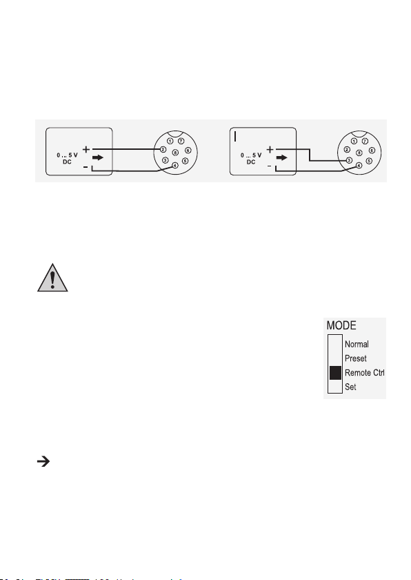
b) Steuerung über externe Spannungsquelle
Das Netzgerät kann mit einer externen Spannungsquelle von 0 bis 5 V/DC über den gesamten
Bereich für Spannung und Strom ferngesteuert werden.
Zum Anschluss gehen Sie wie folgt vor:
Verbinden Sie die Anschlussleitungen der Remote-Buchse wie abgebildet:
V
Spannungseinstellung “V”
• Anschluss 2 zum Pluspol (+) der
externen Steuerspannung.
• Anschluss 4 zum Minuspol (-) der
externen Spannungsquelle.
Die Spannung am Fernsteueranschluss darf 5 V nicht überschreiten.
Die Anschlüsse dürfen nicht kurzgeschlossen werden.
1. Schalten Sie das Netzgerät aus und verbinden dann die Remote-Buchse
mit dem rückseitigen Fernsteuerungsanschluss Remote Control.
Verschrauben Sie den äußeren Befestigungsring.
2. Regeln Sie die Spannung der externen Spannungsquelle auf 0 V.
3. Schalten Sie das Netzgerät ein.
4. Stellen Sie den rückseitigen Wahlschalter MODE (8) in Position Remote
Ctrl. Die Kontrollanzeige REAR CONTROL (2) leuchtet.
5. Über die externe Spannungsquelle kann nun der gewünschte
Ausgangswert eingestellt werden. Kontrollieren Sie den gesamten
Einstellbereich auf korrekte Funktion. Die Ausgangsspannung kann am
Display kontrolliert werden.
Schließen Sie bei der Überprüfung der Stromregelung die rückseitigen Anschlussbuchsen
MAIN OUTPUT (7) mit einem ausreichend dicken Kabel kurz (mind. 8 mm2). Kontrollieren Sie
den gesamten Einstellbereich auf korrekte Funktion.
Wird die Fernsteuerfunktion nicht mehr benötigt, stellen Sie den Wahlschalter MODE (8) in Position
Normal.
20
Stromeinstellung “I“:
• Anschluss 3 zum Pluspol (+) der
externen Steuerspannung
• Anschluss 4 zum Minuspol (-) der
externen Spannungsquelle
Page 21
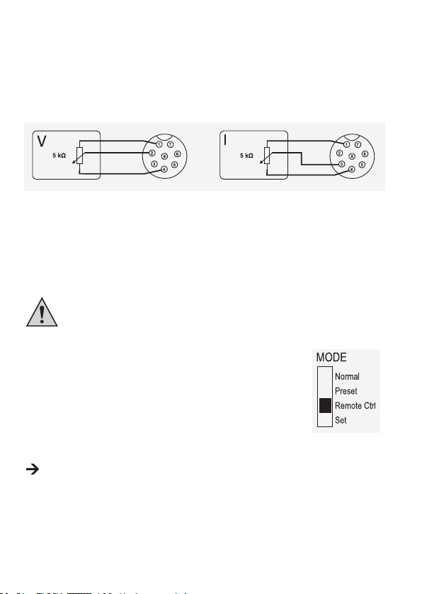
c) Steuerung über einen regelbaren Widerstand (Poti)
Das Netzgerät kann mit einem externen Poti (5 kOhm) über den gesamten Bereich für Spannung und
Strom ferngesteuert werden.
Zum Anschluss gehen Sie wie folgt vor:
Verbinden Sie die Anschlussleitungen der Remote-Buchse wie abgebildet:
Spannungseinstellung “V”
• Anschluss 1 an einem Ende des
Widerstandes.
• Anschluss 2 am mittleren Schleifkontakt
des Widerstandes.
• Anschluss 4 am zweiten Ende des
Widerstandes.
Die Anschlüsse 1 und 4 dürfen nicht kurzgeschlossen werden.
1. Schalten Sie das Netzgerät aus und verbinden dann die Remote-Buchse
mit dem rückseitigen Fernsteuerungsanschluss Remote Control.
Verschrauben Sie den äußeren Befestigungsring.
2. Schalten Sie das Netzgerät ein.
3. Stellen Sie den rückseitigen Wahlschalter MODE (8) in Position Remote
Ctrl. Die Kontrollanzeige REAR CONTROL (2) leuchtet.
4. Über das externe Poti können die gewünschten Ausgangswerte eingestellt
werden. Kontrollieren Sie den gesamten Einstellbereich auf korrekte
Funktion. Die Ausgangsspannung kann am Display kontrolliert werden.
Schließen Sie bei der Überprüfung der Stromregelung den rückseitigen Hauptausgang MAIN
OUTPUT (7) mit einem ausreichend dicken Kabel kurz (mind. 8 mm2). Kontrollieren Sie den
gesamten Einstellbereich auf korrekte Funktion.
Wird die Fernsteuerfunktion nicht mehr benötigt, stellen Sie den Wahlschalter MODE in Position
Normal.
Stromeinstellung “I“:
• Anschluss 1 an einem Ende des
Widerstandes.
• Anschluss 3 am mittleren
Schleifkontakt des Widerstandes.
• Anschluss 4 am zweiten Ende des
Widerstandes.
21
Page 22
d) Ausgang fernsteuern (Ein/Aus)
Der DC-Ausgang kann über einen Schaltkontakt ein- und ausgeschaltet werden.
Zum Anschluss gehen Sie wie folgt vor:
1. Verbinden Sie die Anschlussleitungen der Remote-Buchse wie abgebildet.
2. Kontaktieren Sie Anschluss 4 und 5 zu einem potentialfreien Schaltkontakt.
3. Wenn der Ausgang ausgeschaltet ist, blinken die Statusanzeigen C.V. und C.C. (1). Die Anzeige (1)
zeigt daraufhin die derzeitigen Einstellungen der Ausgangsspannung und des Ausgangsstroms an.
4. Wenn der Ausgang ausgeschaltet ist, können Sie die Ausgangswerte mit den Einstellreglern für
Spannung (VOLTAGE) (3) und Strombegrenzung (CURRENT) (4) festlegen.
An die Kontakte 4 und 5 darf keine Spannung angelegt werden.
5. Schalten Sie das Netzgerät aus und verbinden dann die RemoteBuchse mit dem rückseitigen Remote-Anschluss. Verschrauben Sie
den äußeren Befestigungsring.
6. Schalten Sie das Netzgerät ein.
7. Stellen Sie den rückseitigen Wahlschalter MODE (8) in Position
Remote Ctrl. Die Kontrollanzeige REAR CONTROL (2) leuchtet.
8. Bei offenem Schaltkontakt ist der DC-Ausgang aktiv, bei geschlossenem
Schaltkontakt wird der DC-Ausgang abgeschaltet. Kontrollieren Sie die
Schaltfunktion auf korrekte Funktion.
9. Bei abgeschaltetem DC-Ausgang erscheint „O P OFF“ im Display.
10. Wird die Fernsteuerfunktion nicht mehr benötigt, stellen Sie den
Wahlschalter MODE in Position Normal.
22
Page 23
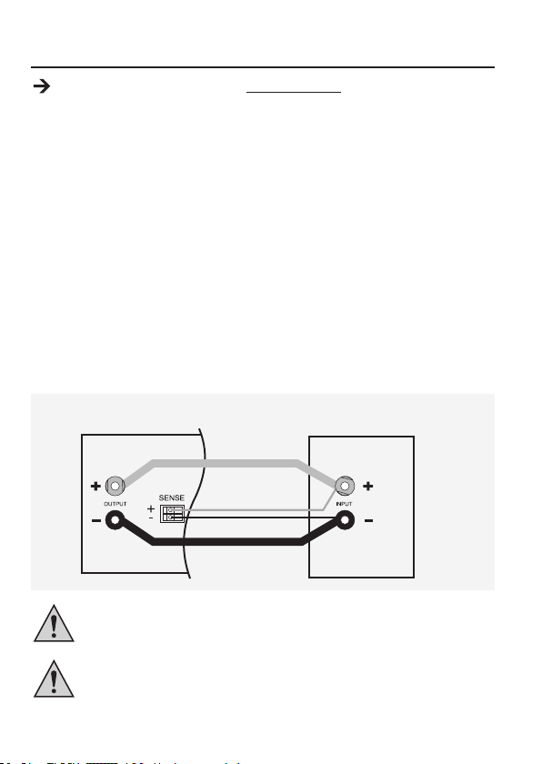
11. SENSE-FUNKTION (1086562)
Die Sense (Sensor)-Funktion ist nur bei Bestell.-Nr. 1086562 verfügbar.
Die Sense-Funktion ist eine automatische Spannungsregelung für den rückseitigen Hochstromausgang
(MAIN OUTPUT) (7). Dazu werden zwei separate Messleitungen parallel zu den Anschlussleitungen
angeschlossen. Auf diesen beiden Messleitungen wird der Spannungsabfall, welcher auf den
Anschlussleitungen auftritt gemessen. Diesen Spannungsabfall gleicht das Labornetzgerät
automatisch aus, so dass am Verbraucher die tatsächlich eingestellte Spannung anliegt.
Zum Anschluss gehen Sie wie folgt vor:
1. Schalten Sie Netzgerät und Verbraucher aus.
2. Verbinden Sie immer erst die Versorgungsleitungen vom Netzgerät zum Verbraucher. Achten Sie
auf richtige Polarität.
3. Drücken Sie an den rückseitigen Anschlussbuchsen SENSE (14) die Klemmenentriegelung mit
einem kleinen Schraubendreher nach innen und stecken die Leitungen in die Klemmöffnungen.
Kontrollieren Sie den festen Sitz.
4. Verbinden Sie nun die beiden Sense-Leitungen polungsrichtig mit dem Verbraucher. Der
Leiterquerschnitt für die Sense-Leitungen muss mindestens 0,34 mm2 betragen.
5. Lösen Sie die Verbindungen immer in umgekehrter Reihenfolge (zuerst die Sense-Leitungen und
dann die Anschlussleitungen).
1086562
Achten Sie darauf, die Sense-Leitungen möglichst nah am Anschlusspunkt des
Verbrauchers zu kontaktieren. Achten Sie unbedingt auf die korrekte Polarität.
Schließen Sie die Sense-Leitungen niemals kurz.
23
Page 24

12. SOFTWARE INSTALLIEREN
Die Software ist mit den Windows® Betriebssystemen XP, 2003, Vista, 7, 8 kompatibel.
1. Legen Sie die beiliegende Software-CD in das DVD-Laufwerk Ihres Computers ein.
2. Installieren Sie den Treiber (USB zu UART Bridge) für Ihr Betriebssystem im Ordner USB CP210x
Drivers...
3. Kopieren Sie den Ordner hcs von der CD in den Applikationsordner Ihres Computers oder einen
Ort Ihrer Wahl.
4. Öffnen Sie die Datei hcs.bat im Ordner hcs. Das Programm startet auf.
13. STEUERUNG MIT PC-SOFTWARE
1. Schalten Sie den Wahlschalter MODE (8) in die Stellung Normal.
2. Schließen Sie das Netzgerät mit Hilfe des USB-Kabels an eine freie USB-Schnittstelle Ihres PCs
an. Verbinden Sie das Kabel mit der USB-Buchse (13) an der Geräterückseite.
3. Schalten Sie das Netzgerät ein.
4. Starten Sie das Programm mit der Datei hcs.bat. Nach dem Aufstarten der Software erfolgt die
Steuerung des Netzgerätes über die Software.
5. Die Kontrollanzeige REAR CONTROL (2) leuchtet auf. Das Produkt reagiert auf keine Eingaben
durch die Bedienknöpfe auf der Gerätevorderseite mehr.
24
Page 25
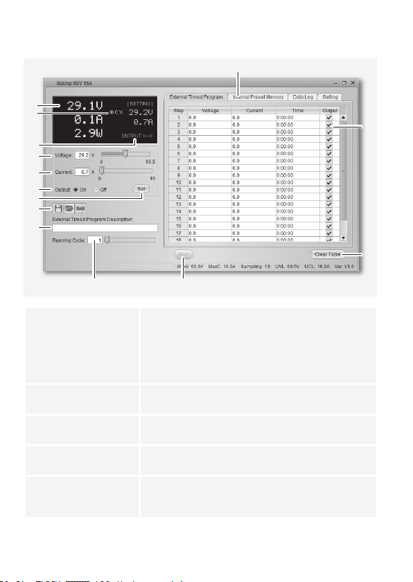
a) Betriebselemente der Software und Grundbetrieb
A
N
M
L
K
J
I
H
G
F
DE
B
C
A Funktionsregisterkarten Wechseln Sie die Funktionsansicht auf der rechten Seite
zwischen:
• Externes Zeitprogramm (External Timed Program)
• Interner Voreinstellungsspeicher (Internal Preset Memory)
• Datenaufzeichnung (Data Log)
• Einstellungen (Setting)
B Datenerfassungstabelle Das Datenerfassungsfeld für die externe Zeitprogrammfunktion.
Die maximale Anzahl an Aktionen beträgt 20.
C Tabelleninhalt löschen Löschen Sie sämtliche Daten in der Datenerfassungstabelle für
die externe Zeitprogrammfunktion.
D Start/Stopp Starten (Run) bzw. stoppen (Stop) Sie das externe Zeitprogramm
gemäß den in der Datenerfassungstabelle vorliegenden Werten.
E Anzahl Arbeitsabläufe Die Anzahl an Arbeitsabläufen, die das Zeitprogramm
durchlaufen wird. Gültige Werte sind 0 – 999, wobei 0 einen
unendlichen Arbeitsablauf bedeutet.
25
Page 26
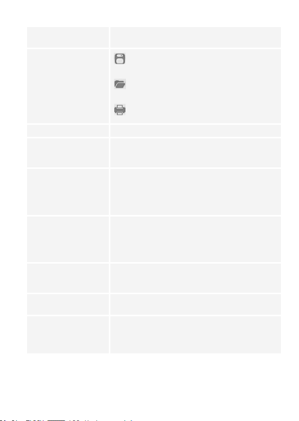
F Tabellenbeschreibung Ein Textfeld, in dem eine Tabellenbeschreibung eingetragen
G Dateiverwaltung
H Einstellungen übernehmen Eingestellte Spannung und Strom übernehmen und übertragen.
I Ausgang ein (On) / aus (Off) Stromversorgung aktivieren / deaktivieren. Bestätigen Sie die
J Strom In diesem Feld können Sie die Stromstärke zur Stromversorgung
K Spannung In diesem Feld können Sie die Spannung zur Stromversorgung
L Ausgang ein / aus Stromversorgung aktivieren / deaktivieren. Klicken Sie auf die
M Einstellungen Hier können Sie die Spannungseinstellung und die
N Status Hier können Sie die aktuelle Spannungs-, Strom- und
werden kann.
Datenerfassungstabelle/Einstellungen als .csv Datei
exportieren
.csv-formatierte Datenerfassungstabelle/Einstellungen
importieren
Ansicht drucken
Einstellung mit der Eingabetaste (H). Die LED-Anzeige zeigt
“O P OFF” an.
programmieren. Drücken Sie nach Eingabe des Wertes die
Eingabetaste (H), um die Einstellungen zu übernehmen.
Die Stromeinstellung kann auch über den Schieberegler
vorgenommen werden.
programmieren. Drücken Sie nach Eingabe des Wertes die
Eingabetaste (H), um die Einstellungen zu übernehmen.
Die Spannungseinstellung kann auch über den Schieberegler
vorgenommen werden.
Schaltäche. Ist die Stromversorgung deaktiviert, zeigt die LED-
Anzeige “O P OFF” an.
Strombegrenzung der Stromversorgung ablesen.
Leistungsabgabe der Stromversorgung ablesen. C.V. ist
äquivalent zur Konstantspannungsanzeige; C.C ist äquivalent
zur Konstantstromanzeige.
26
Page 27
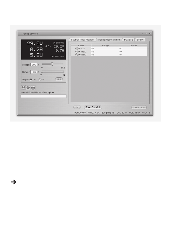
b) Interner Voreinstellungsspeicher
Über die Software können Sie den Voreinstellungsspeicher der Stromversorgung ablesen, einstellen
und anwenden.
• Die Voreinstellungswerte werden automatisch in die Software geladen; falls dies nicht erfolgt,
klicken Sie die Schaltäche Read From PS, um die Information zu laden.
• Wenn Sie einen der Voreinstellungswerte übernehmen möchten, wählen Sie die entsprechende
Option. Betätigen Sie dann die Schaltäche Set (Einstellen).
• Wenn Sie die Voreinstellungswerte verändern wollen, doppelklicken Sie auf das
Spannungswertfeld (Voltage) oder Stromwertfeld (Current) und stellen die gewünschten Werte
mit den Schiebereglern ein.
Die Einstellwerte für Spannung und Strom müssen >0.0 (grösser als null) sein, um die
Einstellwerte über die Schaltäche Set (Einstellen) auf das Gerät übertragen zu können.
• Wenn Sie den Inhalt der Tabelle löschen möchten, betätigen Sie die Schaltäche Clear Table
(Tabelleninhalt löschen).
Mit den Bedienächen der Dateiverwaltung (G) können Sie die Einstellungen importieren und
exportieren oder ausdrucken.
27
Page 28
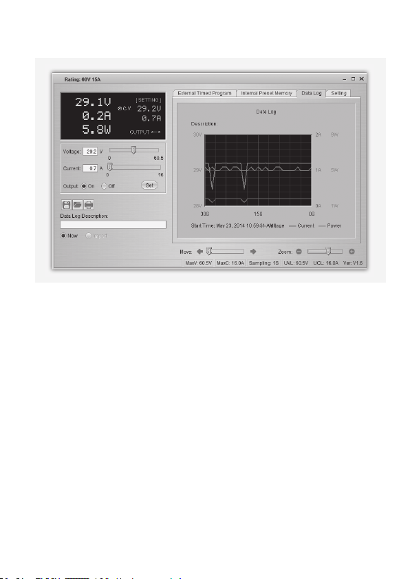
c) Datenaufzeichnung
Sie können das Echtzeit- bzw. aufgezeichnete Spannungs-/Strom-/Leistungs-Diagramm dieser
Funktion sehen.
Mit den Bedienächen der Dateiverwaltung (G) können Sie die Einstellungen importieren und
exportieren oder ausdrucken.
• Wechseln Sie zwischen dem aufgezeichneten Diagramm (Import) und dem Echtzeit-Diagramm
(Now), indem Sie die entsprechende Option in der unteren linken Ecke des Bedienfeldes
auswählen.
• Mit dem Schieberegler Move können Sie das Diagramm zeitlich verschieben.
• Mit dem Schieberegler Zoom können Sie das Diagramm proportional vergössern oder verkleinern.
• Lesen Sie Spannung, Strom und Leistungsverbrauch im Diagramm ab. Diese drei Einheiten sind
farblich markiert und können einfach anhand der Legende auseinandergehalten werden.
28
Page 29
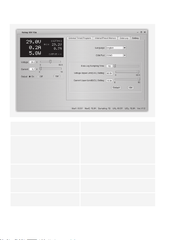
d) Einstellungen
Sprache (Language) Wählen Sie die gewünschte Programmsprache
COMM-Schnittstelle
(COM Port)
DataLog Abtastdauer
(Data Log Sampling Time)
Einstellung Spannungsobergrenze (UVL)
(Voltage Upper Limit (UVL) Setting)
Einstellung Stromobergrenze (UCL)
(Current Upper Limit (UCL) Setting)
• Betätigen Sie zum Speichern der Einstellungen die Schaltäche OK.
• Betätigen Sie zum Zurücksetzen auf die Standardeinstellungen die Schaltäche Default
(Grundeinstellung).
aus.
Der Anschluss zwischen dem PC und der
Stromversorgung. Er wird automatisch während
des Softwarestarts konguriert. Es wird
nicht empfohlen, hier manuelle Änderungen
vorzunehmen.
Das Zeitintervall zwischen zwei Abtastvorgängen.
Begrenzen Sie softwareseitig die Ausgangsspannung.
Begrenzen Sie softwareseitig den Ausgangsstrom.
29
Page 30
14. SCHUTZEINRICHTUNGEN
Das Netzgerät hat verschiedene automatische Schutzeinrichtungen integriert, die das Netzgerät vor
Beschädigungen schützen. Die aktivierten Schutzeinrichtungen werden mit Buchstabencodes im
Display angezeigt und gleichzeitig wird der DC-Ausgang aus Sicherheitsgründen abgeschaltet.
Ist eine Schutzeinrichtung aktiv, muss umgehendst der Verbraucher abgeschaltet
und vom Netzgerät abgeklemmt werden.
Um den Ausgang zu reaktivieren, schalten Sie das Netzgerät aus. Warten Sie bis alle Anzeigen
erloschen sind. Schalten Sie das Netzgerät wieder ein. Das Netzgerät sollte wieder normal
funktionieren. Ist dies nicht der Fall, setzen Sie sich bitte mit unserem Kundendienst in Verbindung.
Folgende Anzeigen sind möglich:
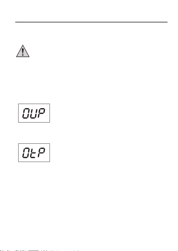
a) Überspannungsabschaltung
• Am DC-Ausgang wurde eine höhere Fremdspannung festgestellt als
das Netzgerät bereitstellt. Der Ausgang wird abgeschaltet.
• Die Spannungspegel für die Abschaltung sind in den technischen
Daten angegeben.
b) Übertemperaturabschaltung
• Der integrierte Temperaturfühler hat eine zu hohe Systemtemperatur
festgestellt. Um eine Überhitzung zu verhindern wird der Ausgang
abgeschaltet.
• Schalten Sie das Netzgerät aus und lassen es mindestens 30
Minuten abkühlen. Kontrollieren Sie nach dem Einschalten, ob der
Lüfter oder die Lüftungsöffnungen blockiert sind. In der EinschaltSelbsttestphase muss der Lüfter hörbar anlaufen. Ist dies nicht der
Fall, setzen Sie sich bitte mit unserem Kundendienst in Verbindung.
30
Page 31

c) Überlastabschaltung
• Bei einer Überlastung am DC-Ausgang wird normalerweise die
Strombegrenzung aktiv. Sollte dies einmal nicht der Fall sein, so
wird eine zweite Schutzfunktion aktiv.
• Schalten Sie umgehendst nach erscheinen dieser Warnmeldung
das Netzgerät ab und kontrollieren die Anschlussdaten des
Verbrauchers. Entfernen Sie den Verbraucher vom DC-Ausgang des
Netzgeräts.
• Schalten Sie das Netzgerät wieder ein und kontrollieren die
Funktion. Bleibt die Fehlermeldung bestehen, setzen Sie sich mit
unserem Kundendienst in Verbindung.
15. WARTUNG UND REINIGUNG
• Trennen Sie das Produkt von der Stromquelle.
• Neben einer gelegentlicher Reinigung oder dem Austauschen der Sicherung ist das Produkt
wartungsfrei.
• Zur Reinigung des Gerätes nehmen Sie ein sauberes, fusselfreies, antistatisches und leicht
feuchtes Reinigungstuch ohne scheuernde, chemische und lösungsmittelhaltige Reinigungsmittel.
a) Netzsicherung wechseln
Lässt sich das Labornetzgerät nicht mehr einschalten, so ist vermutlich die rückseitige
Netzsicherung (12) defekt.
Befolgen Sie die nachstehenden Schritte, um die Hauptsicherung auszutauschen:
1. Schalten Sie das Netzgerät aus und
entfernen alle Anschlusskabel und den
Netzstecker vom Gerät.
2. Drücken Sie mit einem geeigneten
Schlitzschraubendreher den rückseitigen
Sicherungshalter (12) mit einer Hebelbewegung aus der Halterung.
3. Ersetzen Sie die defekte Sicherung
gegen eine neue Feinsicherung des
selben Typs und Nennstromstärke. Den
Sicherungswert nden Sie im Kapitel
„Technische Daten“.
4. Drücken Sie den Sicherungseinsatz in den
Sicherungshalter.
Sicherungen sind Ersatzteile und werden nicht durch die Gewährleistung/Garantie
abgedeckt.
31
Page 32

16. BEHEBUNG VON STÖRUNGEN
Mit dem Labor-Netzgerät haben Sie ein Produkt erworben, welches zuverlässig und betriebssicher ist.
Dennoch kann es zu Problemen oder Störungen kommen.
Hier möchten wir Ihnen beschreiben, wie Sie mögliche Störungen leicht selbst beheben können:
Beachten Sie unbedingt die Sicherheitshinweise!
Fehler Mögliche Ursache
Das Netzgerät lässt sich nicht
einschalten.
Angeschlossene Verbraucher
funktionieren nicht.
Die Kontrollanzeige REAR
CONTROL leuchtet. Das Gerät
kann über die Drehregler nicht
bedient werden.
Anzeige „O P OFF“ leuchtet. Der DC-Ausgang wurde über den Fernsteuerungsanschluss
Der Ausgangsstrom wird auf
5 A begrenzt, obwohl die
Stromeinstellung höher liegt.
Die LED-Kontrollleuchte C.C.
leuchtet.
Die LED-Kontrollleuchte C.V.
leuchtet.
Anzeige „OVP“ Überspannungsabschaltung:
Anzeige „OtP“ Übertemperaturabschaltung:
• Leuchtet am Netzgerät die LED-Kontrollleuchte C.V. oder
C.C?
• Kontrollieren Sie die Netzspannung (evtl. Netzsicherung
im Gerät bzw. Leitungsschutzschalter überprüfen).
• Ist die korrekte Spannung eingestellt ?
• Ist die Polarität korrekt ?
• Überprüfen Sie die technischen Daten der Verbraucher.
Der Fernsteuerbetrieb ist aktiv. Stellen Sie den rückseitigen
Schiebeschalter MODE in Position Normal.
Remote Control (10) oder die Software abgeschaltet.
Der vordere Anschluss wird auf max. 5 A begrenzt. Für höhere
Ströme schließen Sie den Verbraucher am rückseitigen
Haupt-Ausgang an.
Konstantstrombetrieb:
Die voreingestellte Stromstärke wurde überschritten.
Kontrollieren Sie die Stromaufnahme an Ihrem Verbraucher
und erhöhen Sie ggf. die Strombegrenzung am Netzgerät.
Konstantspannungsbetrieb:
Das Netzgerät arbeitet normal. Am Ausgang wird die
eingestellte, konstante Spannung ausgegeben.
Siehe Kapitel „Schutzeinrichtungen“.
Siehe Kapitel „Schutzeinrichtungen“.
32
Page 33

Anzeige „OLP“ Überlastabschaltung:
Andere Reparaturen als zuvor beschrieben sind ausschließlich durch eine
autorisierte Fachkraft durchzuführen. Sollten Sie Fragen zum Umgang des Gerätes
haben, steht Ihnen unser Technischer Support zur Verfügung.
Siehe Kapitel „Schutzeinrichtungen“.
17. ENTSORGUNG
Elektronische Geräte sind Wertstoffe und gehören nicht in den Hausmüll.
Entsorgen Sie das Produkt am Ende seiner Lebensdauer gemäß den geltenden
gesetzlichen Bestimmungen.
Sie erfüllen damit die gesetzlichen Verpichtungen und leisten Ihren Beitrag zum Umweltschutz.
33
Page 34

18. TECHNISCHE DATEN
1086555
Betriebsspannung: 200 – 240 V/AC, 50/60 Hz
Max. Eingangsstrom (230 V/AC): 2,4 A 2,4 A 2,5 A
Max. Ausgangsleistung: 480 W 480 W 480 W
Ausgangsspannung: 1 – 16 V/DC 1 – 32 V/DC 1 – 60 V/DC
Max. Ausgangsstrom 0 – 30 A 0 – 15 A 0 – 8A
Restwelligkeit bei Nennlast (eff.): 5 mV, 50 mA 5 mV, 20 mA 5 mV, 10 mA
Spannungs-Regelverhalten bei 10 – 100 %
Laständerung:
Spannungs-Regelverhalten bei
Netzschwankung (170 – 264 V/AC):
Strom-Regelverhalten bei 10 – 90 %
Laständerung:
Strom-Regelverhalten bei Netzschwankung
(170 – 264 V/AC):
Anzeigegenauigkeit:
OVP-Abschaltpegel von V-Ausgang:
Wirkungsgrad: 85 % 86 % 87 %
Taktfrequenz: 65 – 85 kHz 75 – 95 kHz 65 – 85 kHz
Leistungsfaktor mit aktiver PFC >0,96 >0,96 >0,96
Gerätelüfter: Temperaturgesteuert (0 – 100 %)
Netzsicherung Träge (5 x 20 mm): T3.15AL250V T3.15AL250V T3.15AL250V
Betriebstemperatur: 0 bis +40 ºC
Betriebsluftfeuchtigkeit: 10 – 80 %, nicht kondensierend
Lagertemperatur: -15 bis +70 ºC
Lagerluftfeuchtigkeit 0 – 85 %, nicht kondensierend
Betriebshöhe: max. 2000 m über Meereshöhe (N.N.)
Schutzklasse: 1
Gewicht: 2,6 kg
Abmessungen (B x H x T): 200 x 90 x 215 mm
(DPPS-16-30)
50 mV 50 mV 50 mV
20 mV 20 mV 20 mV
150 mA 100 mA 100 mA
50 mA 50 mA 50 mA
±(0,2% +0,3) V/A ±(0,2% +0,3) V/A ±(0.2% +0.3) V/A
+2 V (1 – 5 V)
+3 V (5 – 16 V)
1086556
(DPPS-32-15)
+2 V (1 – 5 V)
+3 V (5 – 20 V)
+4V(20 – 32V)
1086558
(DPPS-60-8)
+2 V (1 – 5 V)
+3 V (5 – 20 V)
+4V(20 – 60V)
34
Page 35

1086559
Betriebsspannung: 200 – 240 V/AC, 50/60 Hz
Max. Eingangsstrom (230 V/AC): 3,1 A 3,1 A 3.1 A
Max. Ausgangsleistung: 640 W 640 W 600 W
Ausgangsspannung: 1 – 16 V/DC 1 – 32 V 1 – 60 V
Max. Ausgangsstrom 0 – 40 A 0 – 20 A 0 – 10 A
Restwelligkeit bei Nennlast (eff.): 5 mV, 70 mA 5 mV, 30 mA 5 mV, 10 mA
Spannungs-Regelverhalten bei 10 – 100 %
Laständerung:
Spannungs-Regelverhalten bei
Netzschwankung (170 – 264 V/AC):
Strom-Regelverhalten bei 10 – 90 %
Laständerung:
Strom-Regelverhalten bei Netzschwankung
(170 – 264 V/AC):
Anzeigegenauigkeit: ±(0.2% +0.3) V/A ±(0.2% +0.3) V/A ±(0.2% +0.3) V/A
OVP-Abschaltpegel von V-Ausgang:
Wirkungsgrad: 85 % 87 % 89 %
Taktfrequenz: 65 – 85 kHz 75 – 95 kHz 65 – 85 kHz
Leistungsfaktor mit aktiver PFC >0,97 >0,97 >0,97
Gerätelüfter: Temperaturgesteuert (0 – 100 %)
Netzsicherung Träge (5 x 20 mm): T4.0AL250V T4.0AL250V T4.0AL250V
Betriebstemperatur: 0 bis +40 ºC
Betriebsluftfeuchtigkeit: 10 – 80 %, nicht kondensierend
Lagertemperatur: -15 bis +70 ºC
Lagerluftfeuchtigkeit 0 – 85 %, nicht kondensierend
Betriebshöhe: max. 2000 m über Meereshöhe (N.N.)
Schutzklasse: 1
Gewicht: 2,6 kg
Abmessungen (B x H x T): 200 x 90 x 215 mm
(DPPS-16-40)
50 mV 50 mV 50 mV
20 mV 20 mV 20 mV
150 mA 100 mA 100 mA
50 mA 50 mA 50 mA
+2 V (1 – 5 V)
+3 V (5 – 16 V)
1086560
(DPPS-32-20)
+2 V (1 – 5 V)
+3 V (5 – 20 V)
+4 V (20 – 32 V)
1086561
(DPPS-60-10)
+2 V (1 – 5 V)
+3 V (5 – 20 V)
+4 V (20 – 60 V)
35
Page 36

1086562
Betriebsspannung: 200 – 240 V/AC, 50/60 Hz
Max. Eingangsstrom (230 V/AC): 4,7 A 4,5 A 4,5 A
Max. Ausgangsleistung: 960 W 960 W 900 W
Ausgangsspannung: 1 – 16 V/DC 1 – 32 V/DC 1 – 60 V/DC
Max. Ausgangsstrom 0 – 60 A 0 – 30 A 0 – 15 A
Restwelligkeit bei Nennlast (eff.): 5 mV, 100 mA 5 mV, 40 mA 5 mV, 15 mA
Spannungs-Regelverhalten bei 10 – 100 %
Laständerung:
Spannungs-Regelverhalten bei
Netzschwankung (170 – 264 V/AC):
Strom-Regelverhalten bei 10 – 90 %
Laständerung:
Strom-Regelverhalten bei Netzschwankung
(170 – 264 V/AC):
Anzeigegenauigkeit:
OVP-Abschaltpegel von V-Ausgang:
Wirkungsgrad: 86 % 90 % 90 %
Taktfrequenz: 65 – 85 kHz 75 – 95 kHz 65 – 85 kHz
Leistungsfaktor mit aktiver PFC >0,97 >0,97 >0,97
Gerätelüfter: Temperaturgesteuert (0 – 100 %)
Netzsicherung Flink (5 x 20 mm): F8AL250V F8AL250V F8AL250V
Betriebstemperatur: 0 bis +40 ºC
Betriebsluftfeuchtigkeit: 10 – 80 %, nicht kondensierend
Lagertemperatur: -15 bis +70 ºC
Lagerluftfeuchtigkeit 0 – 85 %, nicht kondensierend
Betriebshöhe: max. 2000 m über Meereshöhe (N.N.)
Schutzklasse: 1
Gewicht: 3,2 kg
Abmessungen (B x H x T): 200 x 90 x 275 mm
(DPPS-16-60)
50 mV 50 mV 50 mV
20 mV 20 mV 20 mV
200 mA 150 mA 100 mA
50 mA 50 mV 50 mV
±(0.2% +0.3) V/A ±(0.2% +0.3) V/A ±(0.2% +0.3) V/A
+2 V (1 – 5 V)
+3 V (5 – 16 V)
1086563
(DPPS-32-30)
+2 V (1 – 5 V)
+3 V (5 – 20 V)
+4 V (20 – 32V)
1086564
(DPPS-60-15)
+2 V (1 – 5 V)
+3 V (5 – 20 V)
+4 V (20 – 60V)
36
Page 37

19. ZUSÄTZLICHE FUNKTIONEN
Diese Ergänzung gilt nur für Geräte mit Firmware-Version 3.x.
a) Manuelle Nullstellung des Geräts
Jedes Mal, wenn Sie das Netzteil einschalten, wird es automatisch auf Null gestellt. Falls Sie das
Gerät während des Betriebs auf Null zurückstellen müssen, es jedoch nicht erneut starten möchten,
dann führen Sie die Nullstellung manuell durch.
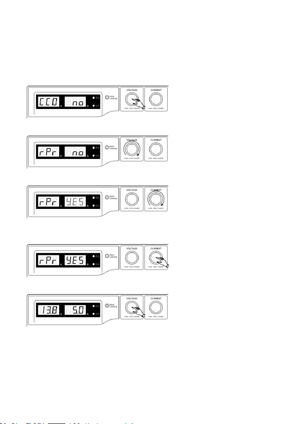
1. Halten Sie den Regler VOLTAGE ca. 30 Sek. gedrückt, um den MENÜ-Modus aufzurufen. „CCO“
und „no“ erscheinen im Display.
2. Drehen Sie den Regler CURRENT, bis „CCO“ und „YES“ im Display erscheinen.
3. Drücken Sie einmal den Regler CURRENT, um die Nullstellung durchzuführen. Die Anzeige „YES“
leuchtet im Display auf, um die Nullstellung zu bestätigen.
4. Drücken Sie den Regler VOLTAGE, um den MENÜ-Modus zu verlassen.
37
Page 38
b) Rückstellung der Speicherplätze (P1/P2/P3) auf Werkseinstellung
Das Netzteil ermöglicht die Speicherung von drei Spannungswerten (inklusive der StromEinstellungen) auf drei unterschiedlichen Speicherplätzen: P1, P2, und P3. Falls Sie die Speicherplätze
auf die Werkseinstellungen zurücksetzen möchten, gehen Sie wie folgt vor.
1. Halten Sie den Regler VOLTAGE ca. 30 Sek. gedrückt, um den MENÜ-Modus aufzurufen. „CCO“
und „no“ erscheinen im Display.
2. Drehen Sie den Regler VOLTAGE, bis „rPr“ und „no“ im Display erscheinen.
3. Drehen Sie den Regler CURRENT, bis „rPr“ und „YES“ im Display erscheinen.
4. Drücken Sie einmal den Regler CURRENT, um die Speicherplätze zurückzusetzen. „YES“ leuchtet
im Display auf, nachdem die Werte erfolgreich zurückgesetzt wurden.
5. Drücken Sie den Regler VOLTAGE, um den MENÜ-Modus zu verlassen.
38
Page 39

CONTENTS
1. Introduction ..........................................................................................................................40
2. Intended Use ........................................................................................................................41
3. Delivery content ...................................................................................................................42
4. Symbol explanation ..............................................................................................................43
5. Safety instructions ................................................................................................................44
a) Persons / Product ...........................................................................................................44
b) Miscellaneous .................................................................................................................46
6. Operating elements ..............................................................................................................46
7. Start-up ................................................................................................................................48
a) Connecting the power cable ...........................................................................................48
b) Unit installation................................................................................................................48
c) General informations.......................................................................................................48
8. Normal Operation .................................................................................................................50
a) Set current limitation .......................................................................................................50
b) Set output voltage ...........................................................................................................51
c) Connecting a load ...........................................................................................................51
9. Memory Slot Operation “Preset” and “Set” ...........................................................................53
a) Assigning memory slots with “Set” ................................................................................54
b) Reset to memory slots to default settings .......................................................................54
10. Remote Control Operation “Remote Ctrl” .............................................................................55
a) Preparation of the remote control connection .................................................................55
b) Control through external voltage source .........................................................................56
c) Control through a controllable resistance (poti) ..............................................................57
d) Remote-control output (on/off) ........................................................................................58
11. Sense function (1086562) ....................................................................................................59
12. Software installation .............................................................................................................60
13. Control with the PC software ................................................................................................60
a) Operating elements of the software and the basic operation..........................................61
b) Internal preset memory ...................................................................................................63
c) Data log...........................................................................................................................64
d) Setting .............................................................................................................................65
14. Protective measures ............................................................................................................66
a) Over-voltage protection...................................................................................................66
b) Overheating protection....................................................................................................66
c) Overload protection.........................................................................................................67
15. Maintenance and cleaning ...................................................................................................67
a) Exchanging the fuse .......................................................................................................67
16. Troubleshooting ....................................................................................................................68
17. Disposal ...............................................................................................................................69
18. Technical data ......................................................................................................................70
19. Added functions ...................................................................................................................73
a) Zeroing the unit manually................................................................................................73
b) Resetting output presets (P1/P2/P3) to factory default values ......................................74
39
Page 40

1. INTRODUCTION
Dear Customer,
In purchasing this Voltcraft® product, you have made a very good decision for which we would like
to thank you.
Voltcraft® - In the eld of measuring, charging and network technology, this name stands for
high-quality products which perform superbly and which are created by experts whose concern is
continuous innovation.
From the ambitious hobby electronics enthusiast to the professional user, products from the Voltcraft®
brand family provide the optimum solution even for the most demanding tasks. And the remarkable
feature is: we offer you the mature technology and reliable quality of our Voltcraft® products at
an almost unbeatable price-performance ratio. In this way, we aim to establish a long, fruitful and
successful co-operation with our customers.
We wish you a great deal of enjoyment with your new Voltcraft® product!
All names of companies and products are trademarks of the respective owner. All rights
reserved.
If there are any technical questions, please contact: www.conrad.com/contact
40
Page 41

2. INTENDED USE
The laboratory power unit serves as a potential-free DC voltage source to operate low-voltage
consumers. The adjustable output can be tapped with up to 5 A at the front and up to the full nominal
current at the back. The front output is limited to 5 A and protected against overload. When switching
the outputs of several power supplies in series, voltages of >75 V/DC, which are dangerous to touch,
may be generated. This is why insulated lines/measuring cables must be used for safety reasons for
voltages above this. Connection on the front is performed with 4 mm safety sockets, on the back with
high-current socket screw connectors. The outputs (front and back) are connected to each other.
The connection cables used must be large enough. Where the conductor section
is too small, overheating and re may result.
The output data of the laboratory measuring devices is as follows:
Type Output voltage Output current
DPPS-16-30 1 – 16 V/DC 0 – 30 A
DPPS-32-15 1 – 32 V/DC 0 – 15 A
DPPS-60-8 1 – 60 V/DC 0 – 8 A
DPPS-16-40 1 – 16 V/DC 0 – 40 A
DPPS-32-20 1 – 32 V/DC 0 – 20 A
DPPS-60-10 1 – 60 V/DC 0 – 10 A
DPPS-16-60 1 – 16 V/DC 0 – 60 A
DPPS-32-30 1 – 32 V/DC 0 – 30 A
DPPS-60-15 1 – 60 V/DC 0 – 15 A
Current and voltage can be set continually through digital rotary controls using coarse and ne
settings in order to allow fast and precise value settings. The values are displayed on the structured
LC display. A power limit for constant power operation can be pre-set without a shorting bar.
The power unit can be remote-controlled. An external voltage (0 - 5 V/DC) or external potentiometer
(5 kOhm) can be used to set the output voltage and output current. The DC output is turned on and
off via the a switching contact.
Three freely programmable memory slots can be assigned to different xed voltages and current
limitations. The selection switch is located at the back of the device.
(Total, MAIN + AUX)
41
Page 42

With the software included and the USB connection, the power supply can be controlled by a personal
computer for running cyclical operations. Up to 20 programmable sets of voltage and current at
different time durations can be programmed into the operation and the cyclical operations can be
repeated up to 999 times.
The device is overload- and short-circuit-proof and contains a safety temperature cut-off. The
laboratory power unit is designed in compliance with protection class 1. It is only approved for
connection to shockproof sockets with protective grounding and an alternating current of 230 V/AC
commonly used in households.
Unauthorised conversion and/or modication of the device are inadmissible because of safety and
approval reasons (CE). Any usage other than described above is not permitted and can damage the
product and lead to associated risks such as short-circuit, re, electric shock, etc. Please read the
operating instructions thoroughly and keep them for further reference.
Observe all safety instructions and information within this operating manual.
3. DELIVERY CONTENT
• Laboratory power supply
• Remote connection socket
• Power cable with grounding contact
• USB cable
• CD (software)
• Operating instructions
Up-to-date operating instructions
Download the latest operating instructions at www.conrad.com/downloads or
scan the QR code shown. Follow the instructions on the website.
42
Page 43

4. SYMBOL EXPLANATION
An exclamation mark in a triangle indicates important instructions in this operating manual
which absolutely have to be observed.
The triangle containing a lightning symbol warns of danger of an electric shock or of the
impairment of the electrical safety of the device.
The symbol can be found when you are to be given tips and information on operation.
Only to be used in dry indoor areas.
This product has been CE-tested and meets the required European guidelines.
Grounding wire connection; this screw may not be loosened.
43
Page 44

5. SAFETY INSTRUCTIONS
Read the operating instructions carefully and especially observe the safety
information. If you do not follow the safety instructions and information on proper
handling in this manual, we assume no liability for any resulting personal injury or
damage to property. Such cases will invalidate the warranty/guarantee.
a) Persons / Product
• The device is not a toy. Keep it out of the reach of children and pets.
• Do not leave packaging material lying around carelessly. These may become
dangerous playing material for children.
• Protect the product from extreme temperatures, direct sunlight, strong jolts, high
humidity, moisture, ammable gases, vapours and solvents.
• Do not place the product under any mechanical stress.
• If it is no longer possible to operate the product safely, take it out of operation and
protect it from any accidental use. Safe operation can no longer be guaranteed if the
product:
- is visibly damaged,
- is no longer working properly,
- has been stored for extended periods in poor ambient conditions or
- has been subjected to any serious transport-related stresses.
• Please handle the product carefully. Jolts, impacts or a fall even from a low height can
damage the product.
• Also observe the safety and operating instructions of any other devices which are
connected to the product.
• Products operated using the mains voltage must be kept out of the reach of children.
For this reason, be particularly careful when using the product in the presence of
children. They may try to stick objects into the device through openings in the housing.
This poses a risk of death by electric shock.
• Never pour liquids over electrical appliances and never leave objects lled with liquids
(e.g. vases) on it or in the vicinity. There is a high risk of re or life-threatening electric
shock.
• Operate the product in dry interior spaces only. It must not get damp or wet. Otherwise
there is a risk of a life-threatening electric shock!
• In schools, training facilities, hobby or self-service workshops, handling of electrical
devices must be monitored by trained personnel.
• When operating on commercial premises, the relevant accident prevention regulations
of workers’ compensation boards for electrical equipment must be observed.
• Live parts may become exposed when opening covers or removing parts. You must
therefore disconnect the product from all power sources before performing any
maintenance or repairs. Capacitors in the device can still carry a charge even if the
device has been disconnected from all voltage sources.
44
Page 45

• Always lay the cables so that nobody can trip over or become entangled in them. This
poses a risk of injury.
• When working with power supplies or chargers, do not wear any metallic or conductive
chains, bracelets, rings etc. Never connect the power supply or charger with humans
or animals.
• Check the product for damage(s) each time before use. If you discover any damages,
do not use the product. Disconnect the power supply and unplug the mains adapter
from the wall outlet. Then bring the product to a specialised workshop.
• Use only a proper mains socket (230V~/50Hz) connected to the public power supply.
• The mains outlet must be located near to the device and be easily accessible.
• Do not touch the mains cable if it is damaged. First, power down the respective mains
socket (e.g. via the respective circuit breaker) and then carefully pull the mains plug
from the mains socket. Never use the product if the mains cable is damaged.
• A damaged mains cable may only be replaced by the manufacturer, a workshop
commissioned by the manufacturer or a similarly qualied person, so as to prevent any
danger.
• Never plug in or unplug the mains plug when your hands are wet.
• Do not pull the mains adapter out of the wall outlet by its cable!
• The plug must be pulled out of the socket under the following conditions:
- before cleaning the product
- during a thunder storm
- if the product is not being used over a long period.
• Make sure that the product is provided with adequate ventilation during operation. Do
not cover the ventilation openings with magazines, blankets, curtains or similar. Keep a
minimum distance of approx. 15 cm from other objects.
• When setting up the product, make sure that the cable is not pinched, kinked or
damaged by sharp edges.
• Make sure there are no devices with strong electric or magnetic elds such as
transformers, motors, cordless telephones and radio-controlled devices in the vicinity
of the product as these can inuence the product.
• Do not operate the product in places or rooms with unfavourable ambient conditions.
This can damage the sensitive electronics found inside the product and can potentially
pose life-threatening risks. Poor ambient conditions are:
- High humidity (> 80 % relative, condensation)
- Humidity, dust, ammable gases, solvent vapours, benzine
- High ambient temperatures (> approx. +50 ºC)
- Electromagnetic elds (motors, transformers, audio systems for model building etc.)
or electrostatic elds
45
Page 46

• The product should not be used immediately after it has been brought from an area
of cold temperature to an area of warm temperature. Condensed water might destroy
the product. Wait until the product adapts to the new ambient temperature before use.
b) Miscellaneous
• Consult an expert when in doubt about operation, safety or connection of the device.
• Maintenance, modications and repairs are to be performed exclusively by an expert
or at a qualied shop.
• If you are not sure about the correct connection or use, or if questions arise which
are not covered by these operating instructions, please do not hesitate to contact our
technical support or another qualied specialist.
6. OPERATING ELEMENTS
1. LED panel meter display with C.V. (Constant voltage) and C.C (Constant current) indicator
2. Control indicator REAR CONTROL (Control over rear side)
3. Control knob VOLTAGE (Output voltage)
4. Control knob CURRENT (Output current)
5. On/Off switch POWER (on/off)
6. Terminals AUX. OUTPUT 5A MAX. (Auxiliary output terminals)
7. Terminals MAIN OUTPUT (Output terminals)
8. Selection switch MODE (Mode selection)
9. Selection switch RECALL (Recall)
10. Remote control terminal Remote Control
11. Cooling fan protective grille
12. Power input and fuse
13. USB port
14. Terminals SENSE (Sensor terminals)
46
Page 47

1086555 / 1086556 / 1086558 1086559 /
1086560 / 1086561 / 1086562 /
1086563 / 1086564
2
3
1
5
1086555 / 1086556 / 1086558 1086559 / 1086560 / 1086561
1086563 / 1086564
9
8
7
10
13
1086562
14
4
6
11
12
47
Page 48

7. START-UP
The laboratory power unit is not a charger. To charge batteries, use suitable
chargers with a charging current cut-off.
During a longer period of operation under nominal load, the surface of the housing
will heat up. Attention! Risk of burns! Therefore, make sure that there is adequate
ventilation of the power unit and never operate it partly or fully covered to avoid
any damage.
When connecting a consumer, ensure that it is not connected when switched on.
A switched-on consumer can result in sparks when connecting to the output
terminals of the power unit, which in turn can damage the sockets or the connected
cables and/or their clamps.
If your power unit is not required, switch it off and disconnect it from the mains.
The displays remain on for a few seconds after it is switched off to unload the
internal capacitors and to store the last parameters that were set.
Always ensure a sufcient conductor cross-section for the DC connection lines,
since overload may cause re in the line.
a) Connecting the power cable
1. Connect the supplied grounding mains cable to the power input (12) on the power unit. Ensure
a tight t.
2. Connect the power cable to a shockproof mains socket with protective grounding. The maximum
length of the power cable to the outlet must not exceed 3 m.
b) Unit installation
Place the laboratory power unit on a stable, level and robust surface. Make sure that ventilation slots
in the casing are not covered up.
c) General informations
The laboratory power unit is micro-processor-controlled and is operated through two digital controls
(incremental encoders without end position) with sensor function. This enables ne and coarse control
via a control.
48
Page 49

After the device switches on, a system check is performed. The test status is displayed on the two
displays. The displays are in the following order:
Display of the current software state.
Segment test to determine if the display works with
all its individual segments.
Then the LED displays C.V., C.C. and REAR
CONTROL are tested.
System test of the protective measures starts.
The over-voltage protection is tested.
The over-load protection is tested.
The over-temperature protection is tested.
Fan test The fan is shortly tested throughout the
speed range.
For a short time, the fan speed increases audibly.
The remote control function for “output out” is
tested.
After this step, the device switches to the regular
operating display mode.
49
Page 50
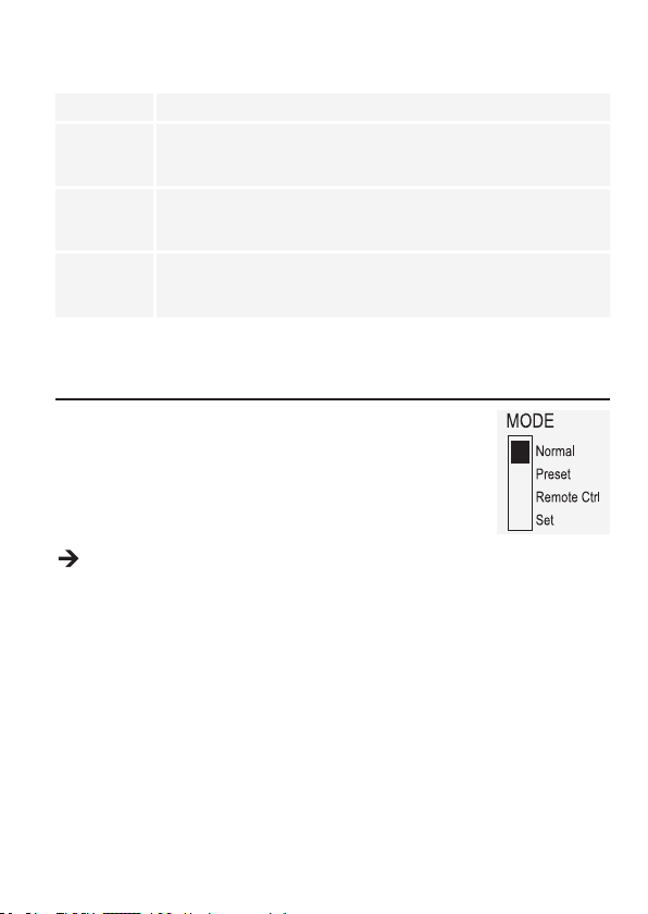
The power unit enables operation in 4 modes. These modes are selected by the selection switch
MODE (8) slider on the back. The following modes are possible:
Normal Normal operation. Voltage and current are adjusted on the front.
Preset Memory slot operation Three xed voltages can be stored in the device and
Remote Ctrl Remote control operation. The power unit can be remote-controlled via
Set Settings operation. The three preset slots can be programmed freely. Select the
The separate operating modes are described in more detail in the following.
directly selected through this Preset function. The memory slot is selected with
the selection switch RECALL (9). The front controls are inactive.
an external voltage or external potentiometer. The remote settings can be
performed for voltage and current. The front controls are inactive.
memory slot with the selection switch RECALL (9) and make the settings using
the control knobs (3, 4).
8. NORMAL OPERATION
In normal operation, the power unit can be operated through the front
controls. Ensure that the selection switch MODE is in the Normal position.
Remove any connected consumers from output (6 or 7).
Switch on the power unit at the On/Off switch POWER (5). The display (1)
lights up, and after a short self test, the current and voltage displays appear.
Set the current limitation before setting any voltages. If the current value is too high, your
connection lines can be damaged; if it is too low (<1 A), the output voltage can be limited.
a) Set current limitation
Limiting the output current is a protection mechanism to protect the consumer or connection cables.
Current limitation can be pre-set at the output without any short circuit. The power unit then supplies
the maximum current set.
1. Remove any connected consumers from the power unit.
2. Switch on the power unit at the On/Off switch POWER (5). The display (1) lights up, and after a
short self test, the current and voltage displays appear.
3. Set the current limitation at the control knob CURRENT (4) according to your application.
4. Turn the control and a current limitation value appears.
50
Page 51

Where no setting is made within 2 seconds, the display switches back to the current
current display.
5. Turn the control to the left or right to set the current limitation. After switching on, the ne settings
area (0.1 A) is always active. This is indicated by a slightly lighter digit. Press the rotary control
slightly from the front. The decimal position (1.0 or 0.1) of the setting range changes each time you
press. Turning changes the value.
6. Settings can be made coarsely (whole numbers) or ne (by tenths).
7. Where the desired current value was set, the display switches back to normal display after 2 seconds.
If the preset current is reached in normal operation, the power unit switches to current limitation
mode and reduces the voltage value. This operation is signalled with the red status display
C.C. (1).
b) Set output voltage
The output voltage can be set at the control knob VOLTAGE (3) control. The coarse and ne control
is performed in the same way as for setting the current limitation.
With the large control range, it is possible that the voltage setting takes approx.
1- 2 seconds to switch from a high to a low voltage value.
In normal mode the device operates in constant voltage mode. This means that the power
unit emits a constant, preset output voltage. This operation is indicated with a green status
LED C.V. (1).
c) Connecting a load
When connecting a consumer, make sure that it is connected to the power unit when
switched off. The maximum current consumption of the device to be connected
must not exceed the capacity indicated in the technical specications.
For serial connection of the outputs with several power supplies, the resulting
voltages can be fatal on contact (> 75 V/DC). As of this voltage, you may only use
insulated accessories.
Avoid the use of non-insulated metallic cables and contacts. All these exposed
areas must be covered with suitable, ame-resistant insulation materials or by other
measures and be protected from direct contact and short circuits.
Ensure a sufcient cable diameter for the intended current.
The power unit has two outputs. These outputs always have the same output voltage. The difference,
however, is in the current carrying capacity.
51
Page 52

Max. 5 A shall be tapped at the terminals AUX. OUTPUT 5A MAX. (6).
A PTC overcurrent protection protects those terminals against overloading and
interrupts the current supply when triggered (>5 A). To reset the unit, immediately
turn it off and let it cool down to room temperature before using it again.
The terminals MAIN OUTPUT (screw sockets) (7) on the back are indicated for full
nominal current. From an output current of 5 A, the screw clamp function of the rear
sockets is recommended to avoid overheating of the plug sockets.
1. Remove any connected consumers from the output.
2. Switch on the power unit at the On/Off switch POWER (5). The operating display (1) lights up and
the current and voltage display appears on the display.
3. Set the parameters according to your specications as described in the chapter “Start-Up”.
4. Check once more that the correct output voltage is set.
5. Connect the plus pole (+) of the consumer with the red socket “+” and the minus pole (-) of the
consumer with the black socket “-” of the respective output (front = AUX. OUTPUT 5A MAX. (6),
rear = MAIN OUTPUT (7)).
Now you can switch on the connected consumer.
The current consumption of the connected consumer is displayed in Ampere (A) in the display (1).
52
Page 53

9. MEMORY SLOT OPERATION “PRESET” AND “SET”
Three xed voltages, including current settings, can be stored in the device with the Set function and
directly selected through the Preset function.
Ex works, all three memory slots (P1, P2, P3) are preset.
They are assigned as follows:
Memory
Type
DPPS-16-30 5 V Maximum 13.8 V Maximum 15 V Maximum
DPPS-32-15 5 V Maximum 13.8 V Maximum 25 V Maximum
DPPS-60-8 5 V Maximum 13.8 V Maximum 55 V Maximum
DPPS-16-40 5 V Maximum 13.8 V Maximum 15 V Maximum
DPPS-32-20 5 V Maximum 13.8 V Maximum 25 V Maximum
DPPS-60-10 5 V Maximum 13.8 V Maximum 55 V Maximum
DPPS-16-60 5 V Maximum 13.8 V Maximum 15 V Maximum
DPPS-32-30 5 V Maximum 13.8 V Maximum 25 V Maximum
DPPS-60-15 5 V Maximum 13.8 V Maximum 55 V Maximum
Make sure that no consumers are connected.
The memory can also be set via the software provided, check the chapter “Control with the
PC software”.
1. Activate the Preset function through the selection switch MODE (8) on the rear.
2. Put the switch in the Preset position. The front LED
indicator REAR CONTROL (2) lights up. The front
control knobs are now inactive.
3. Select the respective memory slot P1, P2 or P3 on
the rear selection switch RECALL (9). The
output voltage is indicated on the display (1).
4. Now you can connect and switch on the consumer.
P1 P2 P3
Voltage Current Voltage Current Voltage Current
respective
2
3
53
Page 54

5. For deactivating the xed voltage function, slide the selection switch MODE (8) back to the Normal
position. The control indicator REAR CONTROL (2) goes out. The device switches back to normal
power unit operation (always remove DC consumers before!).
a) Assigning memory slots with “Set”
All three memory slots can be assigned user-specic values for output voltage and current limitation.
Make sure that no consumers are connected.
1. Activate the Set function through the MODE (8)
slider on the rear. Put the switch in the Set position.
The front control indicator REAR CONTROL (2)
lights up. Select the respective memory slot P1,
P2 or P3 on the selection switch RECALL (9).
The respective values for current and voltage are
indicated on the display (1).
2. The front control knobs (3 and 4) can be used to
set the desired output voltage and current limitation.
3. If required, repeat these steps with the other memory slots.
4. When all parameters are set, slide the selection switch MODE (8) back to the Preset position for
xed voltage operation or to the Normal position for standard operation.
2
3
b) Reset to memory slots to default settings
1. Switch off the power unit.
2. Press the two rotary controls on the front at the same time and keep them pressed.
3. Switch on the power unit. When the displays light up, let go of both rotary controls. The default
settings for the parameters are active again.
54
Page 55

10. REMOTE CONTROL OPERATION “REMOTE CTRL”
Through the built-in remote control terminal Remote control (10), the voltage and current can be
set through an external voltage source or an external adjustable resistance (short “poti”). The remote
control is connected on the remote control terminal Remote control (10). There is a remote socket
included for connection.
In remote-controlled operation, the current control path must also be connected,
since the output otherwise switches to the current limitation mode “C.C.” and limits
the output voltage.
a) Preparation of the remote control connection
1. Turn the lateral screw of the supplied socket and remove the front, black contact socket turning
it slightly.
2. Draw ve connecting cables with a conductor cross-section of at least 0.34mm2 through the metal
sleeve from the rear. Carefully solder these cables to the soldering lugs nos.1, 2, 3, 4 and 5 of the
black contact socket. Ensure that no short circuits are created.
The numbers of the soldering lugs are indicated on the black insulator.
Mark the loose ends of the cables with the corresponding contact numbers (1-5) to avoid confusion.
Insert the black contact jack in the reverse order into the metal sleeve and screw them tight.
The contacts are assigned as follows:
Contact 1 Internal control voltage + 5 V/DC (<50 mA)
Contact 2 Voltage setting
Contact 3 Current setting
Contact 4 Reference ground (“Ground”)
Contact 5 Output on / off
Contact 6 – 8 Not assigned
55
Page 56

b) Control through external voltage source
The power unit can be remote-controlled with an external voltage source from 0 to 5 V/DC throughout
the range for voltage and current.
Proceed as follows for connection:
Connect the connecting cables of the remote sockets as illustrated:
V
Voltage setting “V”
• Connection 2 to the plus pole (+) of the
external control voltage.
• Connection 4 to the minus pole (-) of the
external control voltage.
The voltage on the remote control connection must not exceed 5 V.
The connections must not be shorted.
1. Switch off the power unit and then connect the remote socket to the
remote control terminal Remote Control. Screw on the external
fastening ring.
2. Turn the voltage of the external voltage source to 0 V.
3. Switch on the power unit.
4. Put the selection switch MODE (8) on the rear into the Remote Ctrl
position. The control indicator REAR CONTROL (2) is lit.
5. The desired output value can now be set through the external voltage
source. Control the complete adjustment area for correct function. The
output voltage can be monitored in the display.
Short-circuit the rear terminals MAIN OUTPUT (7) with a sufciently thick cable for checking
the current control (at least 8 mm2). Check the entire setting for proper operation.
If this remote control function is no longer required, put the selection switch MODE (8) to the Normal
position.
56
Current setting “I“:
• Connection 3 to the plus pole (+) of the
external control volltage.
• Connection 4 to the minus pole (-) of
the external control volltage
Page 57

c) Control through a controllable resistance (poti)
The power unit can be remote-controlled with an external poti (5 Kohm) throughout the range for
voltage and current.
Proceed as follows for connection:
Connect the connecting cables of the remote sockets as illustrated.
Voltage setting “V”
• Connection 1 at one end of the
resistance.
• Connection 2 at the centre sliding contact
of the resistance.
• Connection 4 at the second end of the
resistance.
Connections 1 and 4 must not be short-circuited.
1. Switch off the power unit and then connect the remote socket to the
remote control terminal Remote Control. Screw on the external
fastening ring.
2. Switch on the power unit.
3. Put the selection switch MODE (8) on the rear into the Remote Ctrl
position. The control indicator REAR CONTROL (2) is lit.
4. The desired output values can now be set through the external poti.
Control the complete adjustment area for correct function. The output
voltage can be monitored in the display.
Short-circuit the rear terminals MAIN OUTPUT (7) with a sufciently thick cable for checking
the current control (at least 8 mm2). Check the entire setting for proper operation.
If this remote control function is no longer required, put the selection switch MODE (8) to the Normal
position.
Current setting “I“:
• Connection 1 at one end of the
resistance.
• Connection 3 at the centre sliding
contact of the resistance.
• Connection 4 at the second end of the
resitance.
57
Page 58

d) Remote-control output (on/off)
The DC output can be turned on and off via the a switching contact.
Proceed as follows for connection:
1. Connect the connecting cables of the remote sockets as illustrated.
2. Contact connections 4 and 5 with an isolated switching contact.
3. When the output is turned off, the status displays “C.V.” and “C.C.” (1) will ash. The display will
then show the current settings of the output voltage and the output current (1).
4. When the output is turned off, you can set the output values with the control knobs for voltage
(VOLTAGE) (3) and current limiting (CURRENT) (4).
No voltage must be applied to contacts 4 and 5.
5. Switch off the power unit and then connect the remote socket to the rear
remote connection. Screw on the external fastening ring.
6. Switch on the power unit.
7. Put the selection switch MODE (8) on the rear into the Remote Ctrl
position. The control indicator REAR CONTROL (2) display is lit.
8. If the switching contact is open, the DC output is active; if it is closed,
the DC output is switched off. Check the switching function for correct
function.
9. When the DC output is switched off, “O P OFF” is displayed.
10. If this remote control function is no longer required, put the selection
switch MODE (8) to the Normal position.
58
Page 59

11. SENSE FUNCTION (1086562)
The sense function is only available with Item No. 1086562.
The sense function is an automatic voltage control for the rear high-current output (MAIN OUTPUT) (7).
For this, two separate measuring cables are connected parallel to the connecting cables. The
potential drop which occurs on the connecting cables is measured on these two measuring cables.
The laboratory power unit automatically compensates for this voltage drop so that the actually set
voltage is supplied to the consumer.
Proceed as follows for connection:
1. Turn off the power supply unit and the consumer.
2. Always connect the supply cables from the power unit to the consumer rst. Pay attention to
correct polarity.
3. Press the clamp release on the rear terminals SENSE (14) inwards with a small screwdriver and
insert the cables into the terminal openings. Check that they are plugged rmly.
4. Now connect the two sense cables to the consumer observing the correct polarity. The conductor
cross-section for the sense cables must be at least 0.34 mm2.
5. Always slacken the connection in the reverse order (rst of all sense cables and then the
connecting cables).
1086562
Make sure that you contact the sense cables as close as possible to the connecting
point of the consumer. Observe correct polarity.
Never short-circuit the sense cables.
59
Page 60

12. SOFTWARE INSTALLATION
Software is compatible with Windows® operating systems XP, 2003, Vista, 7 ,8
1. Insert the supplied software CD into the DVD drive of your computer.
2. Located in directory USB CP210x Drivers... install the driver (USB to UART Bridge) suitable to
your operating system.
3. Copy the directory hcs from the CD to the computer’s application directory or any location of your
choosing.
4. Open the le hcs.bat in the directory hcs. The progam starts up.
13. CONTROL WITH THE PC SOFTWARE
1. Set selection switch MODE (8) into position Normal.
2. Connect the power supply with the USB cable to a USB hub on your computer. Connect the USB
cable to the USB port (13) on the rear.
3. Turn the power supply on.
4. Start the program with the hcs.bat le. After start-up the power supply is controlled via the program.
5. The control indicator REAR CONTROL (2) lights up. The power supply no longer registers inputs
by the front control knobs.
60
Page 61

a) Operating elements of the software and the basic operation
A
N
M
L
K
J
I
H
G
F
DE
B
C
A Function tabs Switch the function of the window on the right-hand side between:
• External timed program (External Timed Program)
• Internal preset memory (Internal Preset Memory)
• Data log (Data Log)
• Setting (Setting)
B Data entry table The data entry eld for the external timed programming function.
The maximum number of actions is 20.
C Clear Table Clear all the data in the data entry table for the external timed
programming function.
D Run / Stop Run (Run) / Stop (Stop) the external timed program according to
the values in the data entry table.
E Running Cycle The number of cycle that the timed program is going to run. The
value is valid from 0 – 999, where 0 means an innite cycle.
F Table Description A text eld for entering a table description.
61
Page 62

G File management
H Transfer settings Transfer set voltage and current to power supply.
I Ouput on/off Activate/deactivate power supply. Conrm input with button (H).
J Current The eld where you can program the current to the power supply.
K Voltage The eld where you can program the voltage to the power supply.
L Output on/off Activate/deactivate power supply. Click on the control. While the
M Settings You can read the voltage setting and current limitation of the
N Status You can read the present voltage, current and power output of
Export table/settings as .csv le.
Import .csv formatted table/settings
Print current view
The LED display displays “O P OFF”.
After inputting the value, press the enter button (H) to transfer the
settings to the power supply. Optionally, you may set the current
by the slider.
After inputting the value, press the enter button (H) to transfer the
settings to the power supply. Optionally, you may set the voltage
by the slider.
output is deactivated the LED display displays “O P OFF”.
power supply.
the power supply. “C.V” is equivalent to the C.V. indicator; “C.C.”
is equivalent to the C.C. indicator.
62
Page 63

b) Internal preset memory
You can read, set and apply the preset memory of the power supply via the software.
• The preset values are loaded into the software automatically, but if not, press the button Read
From PS button to load the information.
• If you want to use either of the preset values, select the corresponding option. Then press the
button Set.
• If you want to change the preset values, double-click on voltage (Voltage) or current eld (Current)
and set the desired values with the sliders.
The set values for voltage and current must be >0.0 (larger than zero) in order for you to transfer
the settings to the power supply via the button Set.
• If you want to clear the table, press the button Clear Table.
With the buttons for le management (G) you can import, export or print the settings.
63
Page 64

c) Data log
You can see the real-time/recorded voltage-current-power chart in this function.
With the buttons for le management (G) you can import, export or print the settings.
• Switch between recorded diagram (Import) and the real-time diagram (Now) by selecting the
corresponding option in the left bottom corner.
• Shift the diagram by time with the slider Move.
• Proportionally resize the diagram with the slider Zoom.
• Read voltage, current und power consumption from the diagram. These three units are colour-
coded and can easily be distinguished by the legend.
64
Page 65

d) Setting
Language Choose software language.
COM Port The connection between the personal computer
Data Log Sampling Time The time interval between each sampling.
Voltage Upper Limit (UVL) Setting Limit the voltage output from the software side.
Current Upper Limit (UCL) Setting Limit the current output from the software side.
and the power supply. It is automatically
congured during software launch and not
recommended to be changed manually.
• Press the OK button to save the setting.
• Press the Default button to set it back to the default settings.
65
Page 66

14. PROTECTIVE MEASURES
The power unit has several integrated automatic protective measures that protect the power unit from
damage. The activated protective measures are displayed with letter codes and the DC output is
switched off for safety reasons at the same time.
When a protective measures is active, the consumer must be switched off and
disconnected from the power unit immediately.
To reactivate the output, switch off the power unit. Wait until all displays have gone out. Switch on
the power unit again. The power unit should work normally again. Where this is not the case, please
contact our customer service.
The following displays are possible:
a) Over-voltage protection
• A higher external voltage than provided by the power unit was
determined at the DC output. The output is switched off.
• The current levels for switching off are listed in the technical data.
b) Overheating protection
• The integrated temperature sensor determined that the system
temperature is too high. To prevent overheating, the output is
switched off.
• Turn off the power unit and let it cool down for at least 30 minutes.
After switching it on, check if the fan or venitlation apertures are
blocked. During the start-up self-test stage, the fan must start up
audibly. Where this is not the case, please contact our customer
service.
66
Page 67

c) Overload protection
• In case of overload at the DC output, the power limitation is usually
switched on. If this is not the case, the second protective function
becomes active.
• Switch off the power unit at once when this warning message
appears and check the connection data of the consumer. Remove
the consumer from the power unit’s DC output.
• Switch on the power unit again and check its function. If the error
message remains on, please contact our customer service.
15. MAINTENANCE AND CLEANING
• Unplug the product from the power source.
• Apart from an occasional cleaning or exchanging the fuse, this laboratory power unit is
maintenance free.
• Use a clean, lint-free, antistatic and dry cloth to clean the device. Do not use any abrasive or
chemical agents or detergents containing solvents.
a) Exchanging the fuse
If it is no longer possible to switch on the laboratory power unit, the rear mains fuse (12) is probably
defective.
Proceed as follows to replace the mains fuse:
1. Switch off the power unit and remove all the
connection cables and the mains plug from the
device.
2. Lever the rear fuse holder (12) with a suitable
screwdriver from the bracket.
3. Replace the defective fuse with a new ne-wire
fuse of the same type and rated current. The
fuse value is listed in the chapter on “Technical
Data”.
4. Press the fuse into the fuse holder.
Fuses are replacement parts and not covered by the warranty/guarantee.
67
Page 68

16. TROUBLESHOOTING
By purchasing the laboratory power unit, you have acquired a product that is reliable and operationally
safe.
Nevertheless, problems or errors may occur.
For this reason we want to describe how to troubleshoot potential malfunctions:
Always follow the safety instructions!
Error Possible cause
The power unit cannot be
switched on.
Connected consumer devices do
not work.
The control indicator REAR
CONTROL is lit. The device can
not be operated via the rotary
controls.
The “O P OFF” display is lit. The DC output was switched off through the remote control
The output current is limited to
5 A, although the current settings
are higher.
The control indicator C.C. is lit. Constant current operation:
The control indicator C.V. LED
is lit.
Display “OVP” Over-voltage protection:
Display “OtP” Overheating protection:
• Does the indicator C.V. or C.C. light up?
• Check the mains voltage (you may also want to check the
mains fuse in the device or the line circuit breaker).
• Is the voltage set correctly?
• Is the polarity correct?
• Check the technical data of the consumers.
Remote control operation is active. Put the rear MODE slider
into the Normal position.
terminal Remote Control (10) or software.
The output current is limited to 5 A. For higher currents,
connect the consumer to the rear main output.
The preset current was exceeded. Check power consumption
on your consumer and increase the current limitation on your
power unit, if applicable.
Constant voltage operation:
The power unit works normally. The output provides the
constant voltage set.
See chapter PROTECTIVE MEASURES.
See chapter PROTECTIVE MEASURES.
68
Page 69

Display “OLP” Overload-protection:
Repairs other than those described above may only be carried out by an authorised
specialist. If you have any questions concerning the handling of the device, please
do no hesitate to contact our Technical Support.
See chapter “Protective measures”.
17. DISPOSAL
Electronic devices are recyclable waste and must not be disposed of in the household
waste.
At the end of its service life, dispose of the product according to the relevant statutory
regulations.
You thus full your statutory obligations and contribute to the protection of the environment.
69
Page 70

18. TECHNICAL DATA
1086555
Operating voltage: 200 – 240 V/AC, 50/60 Hz
Max. input current (230 V/AC): 2.4 A 2.4 A 2.5 A
Maximum output power: 480 W 480 W 480 W
Output voltage: 1 – 16 V/DC 1 – 32 V/DC 1 – 60 V/DC
Output current: 0 – 30 A 0 – 15 A 0 – 8A
Residual ripple at nominal load: 5 mV, 50 mA 5 mV, 20 mA 5 mV, 10 mA
Voltage control response at 10 – 100 %
load change:
Voltage control response at mains
uctuation (170 – 264 V/AC):
Current control response at 10 – 90 % load
change:
Current control response at mains
uctuation (170 – 264 V/AC):
Display accuracy:
OVP switch-off level of the V output:
Degree of effectiveness: 85 % 86 % 87 %
Clock signal: 65 – 85 kHz 75 – 95 kHz 65 – 85 kHz
Performance factor with active PFC: >0.96 >0.96 >0.96
Device fan: Temperature controlled (0 – 100 %)
Mains fuse slow-blow (5 x 20 mm): T3.15AL250V T3.15AL250V T3.15AL250V
Operating temperature: 0 to +40 ºC
Operating humitiy: 10 – 80 %, non-condensing
Storage temperature: -15 to +70 ºC
Storage humidity: 0 – 85 %, non-condensing
Operating altitude: max. 2000 m above mean sea level
Safety class: 1
Weight: 2.6 kg
Dimensions (W x H x D): 200 x 90 x 215 mm
(DPPS-16-30)
50 mV 50 mV 50 mV
20 mV 20 mV 20 mV
150 mA 100 mA 100 mA
50 mA 50 mA 50 mA
±(0.2% +0.3) V/A ±(0.2% +0.3) V/A ±(0.2% +0.3) V/A
+2 V (1 – 5 V)
+3 V (5 – 16 V)
1086556
(DPPS-32-15)
+2 V (1 – 5 V)
+3 V (5 – 20 V)
+4V(20 – 32V)
1086558
(DPPS-60-8)
+2 V (1 – 5 V)
+3 V (5 – 20 V)
+4V(20 – 60V)
70
Page 71

1086559
Operating voltage: 200 – 240 V/AC, 50/60 Hz
Max. input current (230 V/AC): 3.1 A 3.1 A 3.1 A
Maximum output power: 640 W 640 W 600 W
Output voltage: 1 – 16 V/DC 1 – 32 V 1 – 60 V
Maximum output current: 0 – 40 A 0 – 20 A 0 – 10 A
Residual ripple at nominal load (eff): 5 mV, 70 mA 5 mV, 30 mA 5 mV, 10 mA
Voltage control response at 10 – 100 %
load change
Voltage control response at mains
uctuation (170 – 264 V/AC):
Current control response at 10 – 90 % load
change:
Current control response at mains
uctuation (170 – 264 V/AC):
Display accuracy: ±(0.2% +0.3) V/A ±(0.2% +0.3) V/A ±(0.2% +0.3) V/A
OVP switch-off level of the V output:
Degree of effectiveness: 85 % 87 % 89 %
Clock signal: 65 – 85 kHz 75 – 95 kHz 65 – 85 kHz
Performance factor with active PFC: >0.97 >0.97 >0.97
Device fan: Temperature controlled (0 – 100 %)
Mains fuse slow-blow (5 x 20 mm): T4.0AL250V T4.0AL250V T4.0AL250V
Operating temperature: 0 to +40 ºC
Operating humitiy: 10 – 80 %, non-condensing
Storage temperature: -15 to +70 ºC
Storage humidity: 0 – 85 %, non-condensing
Operating altitude: max. 2000 m above mean sea level
Safety class: 1
Weight: 2.6 kg
Dimensions (W x H x D): 200 x 90 x 215 mm
(DPPS-16-40)
50 mV 50 mV 50 mV
20 mV 20 mV 20 mV
150 mA 100 mA 100 mA
50 mA 50 mA 50 mA
+2 V (1 – 5 V)
+3 V (5 – 16 V)
1086560
(DPPS-32-20)
+2 V (1 – 5 V)
+3 V (5 – 20 V)
+4 V (20 – 32 V)
1086561
(DPPS-60-10)
+2 V (1 – 5 V)
+3 V (5 – 20 V)
+4 V (20 – 60 V)
71
Page 72

1086562
Operating voltage: 200 – 240 V/AC, 50/60 Hz
Max. input current (230 V/AC): 4,7 A 4,5 A 4,5 A
Maximum output power: 960 W 960 W 900 W
Output voltage: 1 – 16 V/DC 1 – 32 V/DC 1 – 60 V/DC
Maximum output current: 0 – 60 A 0 – 30 A 0 – 15 A
Residual ripple at nominal load (eff): 5 mV, 100 mA 5 mV, 40 mA 5 mV, 15 mA
Voltage control response at 10 – 100 %
load change
Voltage control response at mains
uctuation (170 – 264 V/AC):
Current control response at 10 – 90 % load
change:
Current control response at mains
uctuation (170 – 264 V/AC):
Display accuracy:
OVP switch-off level of the V output:
Degree of effectiveness: 86 % 90 % 90 %
Clock signal: 65 – 85 kHz 75 – 95 kHz 65 – 85 kHz
Performance factor with active PFC: >0.97 >0.97 >0.97
Device fan: Temperature controlled (0 – 100 %)
Mains fuse fast-acting (5 x 20 mm): F8AL250V F8AL250V F8AL250V
Operating temperature: 0 to +40 ºC
Operating humitiy: 10 – 80 %, non-condensing
Storage temperature: -15 to +70 ºC
Storage humidity: 0 – 85 %, non-condensing
Operating altitude: max. 2000 m above mean sea level
Safety class: 1
Weight: 3.2 kg
Dimensions (W x H x D): 200 x 90 x 275 mm
(DPPS-16-60)
50 mV 50 mV 50 mV
20 mV 20 mV 20 mV
200 mA 150 mA 100 mA
50 mA 50 mV 50 mV
±(0.2% +0.3) V/A ±(0.2% +0.3) V/A ±(0.2% +0.3) V/A
+2 V (1 – 5 V)
+3 V (5 – 16 V)
1086563
(DPPS-32-30)
+2 V (1 – 5 V)
+3 V (5 – 20 V)
+4 V (20 – 32V)
1086564
(DPPS-60-15)
+2 V (1 – 5 V)
+3 V (5 – 20 V)
+4 V (20 – 60V)
72
Page 73

19. ADDED FUNCTIONS
The supplement is only valid for devices running rmware version 3.x.
a) Zeroing the unit manually
The power supply is auto-zeroed every time you turn it on. In case you need to zero the unit during
operation and do not want to restart it, zero it manually.
1. Press and hold the VOLTAGE control knob for approx. 30 s to enter the MENU mode. “CCO” and
“no” are displayed.
2. Rotate the CURRENT control knob until “CCO” and “YES” are displayed.
3. Press the CURRENT control knob once to zero the unit. “YES” lights up in the display to conrm
successful zeroing.
4. Press the VOLTAGE control knob to exit the MENU mode.
73
Page 74

b) Resetting output presets (P1/P2/P3) to factory default values
The power supply allows for presetting three voltage values (including current settings) by means of
three memory slots: P1, P2, and P3. In case you want to reset the memory slots to the factory default
values during operation, do the following.
1. Press and hold the VOLTAGE control knob for approx. 30 s to enter the MENU mode. “CCO” and
“no” are displayed.
2. Rotate the VOLTAGE control knob until “rPr” and “no” are displayed.
3. Rotate the CURRENT control knob until “rPr” and “YES” are displayed.
4. Press the CURRENT control knob once to reset the preset values. “YES” lights up when the values
have been successfully reset.
5. Press the VOLTAGE control knob to exit the MENU mode.
74
Page 75

SOMMAIRE
1. Introduction ..........................................................................................................................76
2. Utilisation prevue ..................................................................................................................77
3. Contenu de l’emballage .......................................................................................................78
4. Explication des symboles .....................................................................................................79
5. Consignes de sécurité ..........................................................................................................80
a) Personnes / Produit ........................................................................................................80
b) Divers ..............................................................................................................................82
6. Éléments de fonctionnement ................................................................................................82
7. Mise en service ....................................................................................................................84
a) Raccordement du câble réseau ......................................................................................84
b) Installation de l’appareil ..................................................................................................84
c) Généralités......................................................................................................................84
8. Fonctionnement normal .......................................................................................................86
a) Régler de la limitation de courant ...................................................................................86
b) Régler la tension de sortie ..............................................................................................87
c) Branchement d’un consommateur ..................................................................................87
9. Fonctionnement emplacement de mémoire «Preset» et «Set» ...........................................88
a) Les emplacements de mémoire occupent «Set» ............................................................90
b) Réinitialiser les emplacements de mémoire au réglage d’usine .....................................90
10. Fonctionnement à distance «Remote Ctrl» ..........................................................................91
a) Préparation de le connexion de la télécommande ..........................................................91
b) Commande via une source de tension externe ..............................................................92
c) Commande via une résistance réglable (potentiomètre) ................................................93
d) Sortie commande à distance (marche/arrêt)...................................................................94
11. Fonction de détection (1086562) .........................................................................................95
12. Installation du logiciel ...........................................................................................................96
13. Contrôle en utilisant le logiciel pc .........................................................................................96
a) Utilisation du logiciel d‘exploitation et fonctionnement de base ......................................97
b) Mémoire interne préréglée ..............................................................................................99
c) Journal de données ......................................................................................................100
d) Conguration.................................................................................................................101
14. Dispositifs de protection .....................................................................................................102
a) Mise hors tension en cas de surtension........................................................................102
b) Mise hors tension en cas de surchauffe .......................................................................102
c) Mise hors tension en cas de surcharge ........................................................................103
15. Entretien et nettoyage ........................................................................................................103
a) Remplacement du fusible de secteur............................................................................103
16. Dépannage .........................................................................................................................104
17. Élimination des déchets .....................................................................................................105
18. Caractéristiques techniques ...............................................................................................106
19. Fonctions supplémentaires ................................................................................................109
a) Remettre l’unité à zéro manuellement ..........................................................................109
b) Réinitialiser les préréglages de sortie (P1/P2/P3) aux valeurs par défaut ....................11 0
75
Page 76

1. INTRODUCTION
Chère cliente, cher client,
En choisissant un produit Voltcraft®, vous avez choisi un produit d’une qualité exceptionnelle, ce dont
nous vous remercions vivement.
Voltcraft® - Ce nom est en effet garant d’une qualité au dessus de la moyenne dans les domaines de
la mesure, de la recharge ainsi que des appareils de réseau, tous se distinguant par leur compétence
technique, leur abilité, leur longévité et une innovation permanente.
Que vous soyez des électroniciens amateurs ambitionnés ou des utilisateurs professionnels, vous
trouverez dans les produits de la famille Voltcraft® des appareils vous mettant à disposition la solution
optimale pour les tâches les plus exigeantes. Et notre particularité : Nous pouvons vous offrir la
technique éprouvée et la qualité able des produits Voltcraft® à des prix imbattables du point de
vue rapport qualité/prix. Ainsi, nous mettons à votre disposition des produits aptes à satisfaire vos
exigences les plus pointues.
Nous vous souhaitons beaucoup de plaisir avec votre nouvel appareil Voltcraft® !
Tous les noms de société et toutes les désignations de produit sont des marques déposées de
leurs propriétaires respectifs. Tous droits réservés.
Pour toute question technique, veuillez vous adresser à:
France (email): technique@conrad-france.fr
Suisse: www.conrad.ch
76
Page 77

2. UTILISATION PREVUE
L´alimentation de laboratoire sert de source de tension CC sans potentiel pour faire fonctionner les
consommateurs basse tension. La sortie réglable peut être tirée sur l’avant jusqu’à 5 A maxi et sur
l’arrière jusqu’à la puissance électrique nominale. La sortie avant est limitée à 5 A et protégée contre
la surcharge. Les tensions dangereuses > 75 V/CC peuvent être obtenues lors d’un montage en
série des sorties de plusieurs alimentations. A partir de cette tension et pour des raisons de sécurité,
il faut utiliser des ls/câbles de mesure à double isolation. Le raccordement est effectué à l’avant par
des prises de sécurité de 4 mm et à l’arrière par des prises à vis à courant fort. Les sorties (avant et
arrière) sont reliées ensemble.
Les câbles de raccordement utilisés doivent être bien dimensionnés. Une section
de conducteur trop faible peut surchauffer et provoquer des incendies.
Les données de sortie des appareils d’alimentation de laboratoire sont les suivantes:
Type Tension de sortie Courant de sortie
DPPS-16-30 1 – 16 V/CC 0 – 30 A
DPPS-32-15 1 – 32 V/CC 0 – 15 A
DPPS-60-8 1 – 60 V/CC 0 – 8 A
DPPS-16-40 1 – 16 V/CC 0 – 40 A
DPPS-32-20 1 – 32 V/CC 0 – 20 A
DPPS-60-10 1 – 60 V/CC 0 – 10 A
DPPS-16-60 1 – 16 V/CC 0 – 60 A
DPPS-32-30 1 – 32 V/CC 0 – 30 A
DPPS-60-15 1 – 60 V/CC 0 – 15 A
Le réglage de la tension et du courant se fait par des régulateurs numériques approximatif et précis
an de permettre un réglage rapide et précis des valeurs. Les valeurs sont afchées sur l’écran clair.
La limitation de courant pour le fonctionnement à courant constant peut être préréglée sans pont de
court-circuit.
L’alimentation est commandable à distance. La tension de sortie et le courant de sortie peuvent être
réglés par une tension externe (0 - 5 V/CC) ou par un potentiomètre externe (5 kOhm). La sortie CC
peut être activée et désactivée par un contact de sécurité.
Trois emplacements de mémoire librement programmables peuvent être occupés avec des tensions
xes et des limites de courant différentes. Le commutateur se trouve à l’arrière.
(totale, MAIN + AUX)
77
Page 78

Avec le logiciel fourni et la connexion USB, l’alimentation peut être contrôlée par un PC pour exécuter
des opérations cycliques. Plus de 20 jeux de tension et de courant de différentes durées peuvent
être programmés dans l’opération et les opérations cycliques peuvent être répétées jusqu’à 999 fois.
L’appareil est protégé contre les surcharges et les courts-circuits et contient une température de
coupure de sécurité. L’alimentation de laboratoire appartient à la classe de protection 1. Elle est
uniquement homologuée pour le branchement sur une prise de courant de sécurité avec protection
par mise à la terre et une tension alternative domestique de 230V/CA.
La conversion et/ou la modication non autorisées de l’appareil ne sont pas permises pour des
raisons de sécurité et d’approbation (CE). Tout usage autre que celui décrit ci-dessus est interdit, peut
endommager le produit et poser des risques tels que courts-circuits, incendies, chocs électriques, etc.
Prière de lire attentivement le mode d’emploi et de le conserver à titre de référence.
Observez toutes les consignes de sécurité et renseignements contenus dans ce
mode d’emploi.
3. CONTENU DE L’EMBALLAGE
• Appareil d’alimentation pour laboratoire
• Connecteur de raccordement à distance
• Câble d’alimentation avec contact de mise à la terre
• Câble USB
• CD (logiciel)
• Mode d’emploi
Mode d’emploi actualisé
Téléchargez le mode d’emploi le plus récent sur www.conrad.com/downloads ou scannez le code QR
indiqué. Suivez les instructions gurant sur le site Web.
78
Page 79

4. EXPLICATION DES SYMBOLES
Dans ce mode d’emploi, le symbole avec un point d’exclamation dans un triangle signale
des consignes importantes, qui doivent être absolument respectées.
Le symbole de l’éclair dans un triangle met en garde contre tout risque de décharge
électrique ou toute compromission de la sécurité électrique de l’appareil.
Ce symbole peut être rencontré lors de conseils et renseignements qui vous sont donnés sur
e fonctionnement.
Réservé à une utilisation dans des locaux secs.
Cet appareil est homologué CE et répond aux directives nationales et européennes
requises.
Raccordement de conducteur de protection. Cette vis ne doit pas être desserrée.
79
Page 80

5. CONSIGNES DE SÉCURITÉ
Lisez le mode d’emploi avec attention en étant particulièrement attentif aux
consignes de sécurité. En cas de non-respect des consignes de sécurité et des
informations données dans le présent mode d’emploi pour une utilisation correcte
de l’appareil, nous déclinons toute responsabilité en cas de dommage personnel ou
matériel consécutif. En outre, la responsabilité/garantie sera alors annulée.
a) Personnes / Produit
• Ce produit n’est pas un jouet. Gardez-le hors de portée des enfants et des animaux
domestiques.
• Ne laissez pas trainer le materiel d’emballage. Cela pourrait devenir un jouet pour
enfant très dangereux.
• Gardez le produit à l’abri des températures extrêmes, de la lumière du soleil directe,
de secousses intenses, d’humidité élevée, d’eau, de gaz inammables, de vapeurs
et de solvants.
• N’exposez pas le produit à des contraintes mécaniques.
• Si une utilisation en toute sécurité n’est plus possible, cessez d’utiliser le produit et
protégez-le d’une utilisation accidentelle. Une utilisation en toute sécurité n’est plus
garantie si le produit:
- présente des traces de dommages visibles,
- le produit ne fonctionne plus comme il devrait,
- a été stocké pour une période prolongée dans des conditions défavorables ou bien
- a été transporté dans des conditionss très rudes.
• Maniez le produit avec précaution. À la suite de chocs, de coups ou de chutes, même
de faîble hauteur, l’appareil peut être endommagé.
• Respecter également les informations concernant la sécurité et le mode d’emploi pour
les autres appareils connectés à cet appareil.
• Respecter également les informations concernant la sécurité et le mode d’emploi pour
les autres appareils connectés à cet appareil.
• Les appareils nécessitant du courant électrique ne doivent pas être mis entre les mains
des enfants. C’est pourquoi vous devez être particulièrement attentifs à l’utilisation
du produit si des enfants sont présents, en particulier si ceux-ci essayent de mettre
des objets dans les ouvertures du boîtier de l’appareil. Vous encourez un risque
d’électrocution pouvant entraîner la mort.
• Ne versez jamais de liquides sur des appareils électriques et ne posez jamais d’objets
remplis de liquides (comme des vases par exemple) sur ou à proximité de l’appareil.
Vous encourez un risque d’incendie ou d’électrocution pouvant entraîner la mort.
• N’utilisez le produit que dans des pièces fermées et sèches. N’exposez jamais
l’appareil à l’humidité ou à des liquides. Sinon vous encourez un risque d’électrocution
pouvant entraîner la mort.
• Dans les écoles, les centres de formations, les ateliers de loisirs et les ateliers en libre
service l’utilisation d’appareils électriques doit être surveillée par du personnel formé.
80
Page 81

• Dans des locaux commerciaux, veuillez vous tenir aux consignes de prévention
d’accidents des associations professionnelles d’installations et de systèmes
électriques.
• Lors de l’ouverture des couvercles ou de l’enlèvement de pièces, des éléments
conducteurs d’électricité peuvent être dégagés. Pour cette raison, débranchez le
produit de toutes les sources d’énergie avant un entretien ou une mise en état. Les
condensateurs dans l’appareil peuvent conserver des charges, même si l’appareil a
été déconnecté de toute source de tension.
• Placez les câbles de façon à éviter que des personnes ne trébuchent ou ne restent
accrochées à ceux-ci. Cela entraîne des risques de blessures.
• Ne portez pas de bijoux métalliques tels que des bracelets, des bagues, des colliers
etc. lorsque vous manipulez les alimentations électriques ou des chargeurs. Ne reliez
en aucun cas les alimentations électriques ou des chargeurs à des humains ou des
animaux.
• Avant chaque utilisation, vériez que le produit ne soit pas endommagé. Si vous
constatez des dommages, n’utilisez plus le produit. Débranchez l’appareil du secteur
et enlevez l’alimentation de la prise de courant. Portez ensuite le produit dans un atelier
de réparation spécialisé.
• Utilisez uniquement une prise de courant répondant aux normes (230V~/50Hz) du
réseau d’alimentation électrique public.
• La prise de courant doit être située à proximité de l’appareil et être facilement
accessible.
• Ne touchez pas le cordon d’alimentation s’il est endommagé. La prise secteur
respective doit être d’abord mise hors tension (par exemple via le disjoncteur respectif)
vous pouvez ensuite retirer soigneusement la che de la prise de courant. Ne jamais
utiliser le produit si le câble d’alimentation est endommagé.
• Un câble d’alimentation endommagé ne doit être remplacé uniquement par le fabricant,
un atelier commandité par le fabricant ou une personne qualiée, an d’éviter tout
danger.
• Ne jamais brancher ou débrancher la prise secteur lorsque vos mains sont humides.
• Ne pas débrancher l’alimentation en tirant sur son câble!
• L’alimentation doit être retirée de la prise de courant dans les conditions suivantes :
- avant le nettoyage du produit
- en cas de tempête
- si le produit n’est pas utilisé pendant un temps prolongé.
• Pendant l’utilisation, veillez à ce que le produit dispose d’une aération sufsante. Ne
couvrez pas les ouvertures d’aération avec des journaux, des couvertures, des rideaux
ou des objets similaires. Respectez une distance minimale de 15cm avec les autres
objets.
• Lors de l’installation du produit, assurez-vous que les câbles ne soient pas écrasés,
pliés ou endommagés par des bords coupants.
81
Page 82

• Ne placez aucun appareil ayant des champs électromagnétiques puissants tels que
des transformateurs, des moteurs, des téléphones sans l, des appareils de radio etc.
à proximité du produit, car il pourrait interférer avec le produit.
• N’utilisez pas le produit dans des endroits ou des locaux présentant des conditions
défavorables. Cela pourrait conduire à l’endommagement de l’électronique très
sensible à l’intérieur du produit et peut avoir pour conséquence des dangers mortels
Les conditions défavorables sont :
- Une humidité de l’air élevée (> 80 % d’humidité relative, condensation)
- Humidité, de la poussière, des gaz inammables, des vapeurs de solvants, de
l’essence
- Une température ambiante élevée (> à env. + 50 °C)
- Des champs électromagnétiques (moteurs, transformateurs, systèmes audio pour
le modélisme etc.) ou des champs électrostatiques
• Ne pas utiliser le produit immédiatement après l’avoir passé d’une zone froide à une
zone chaude. De l’eau de condensation risque de détruire le produit. Attendre que le
produit se soit adapté à la nouvelle température ambiante avant utilisation.
b) Divers
• Adressez-vous à un technicien spécialisé si vous avez des doutes concernant le mode
de fonctionnement, la sécurité ou le raccordement de l‘appareil.
• Tout entretien, ajustement ou réparation ne doit être effectué que par un spécialiste
ou un atelier spécialisé.
• Si vous n’êtes pas sûr de la bonne connexion ou de la bonne utilisation, ou si vous avez
une question qui n’est pas couvert par ces instructions, n’hésitez pas à contacter notre
support technique ou un spécialiste qualié.
6. ÉLÉMENTS DE FONCTIONNEMENT
1. Écran LED avec afchage de la C.V. (tension constante) et du C.C (courant constant)
2. Indicateur de contrôle arrière «REAR CONTROL»
3. Bouton «VOLTAGE» (contrôle de la tension de sortie)
4. Bouton «CURRENT» (contrôle du courant de sortie)
5. Interrupteur «POWER» (Marche/Arrêt)
6. «AUX .OUTPUT 5A MAX» (Terminaux de sortie auxiliaires)
7. «MAIN OUTPUT» (Terminaux de sortie)
8. Commutateur de sélection «MODE» (séléction du mode)
9. Commutateur de sélection «RECALL» (rappel)
10. Borne de la télécommande «Remote Control»
11. Grille d’admission de l’air du ventilateur de refroidissemen
12. Alimentation et fusible
13. Port USB
14. Terminaux «SENSE» (Terminaux de détection)
82
Page 83

1086555 / 1086556 / 1086558 1086559 /
1086560 / 1086561 / 1086562 /
1086563 / 1086564
2
3
1
5
1086555 / 1086556 / 1086558 1086559 / 1086560 / 1086561
1086563 / 1086564
9
8
7
10
13
1086562
14
4
6
11
12
83
Page 84

7. MISE EN SERVICE
L’alimentation de laboratoire n’est pas un chargeur d’accumulateurs. An de
recharger des accumulateurs, utilisez un chargeur adéquat muni d’un dispositif
d’interruption de charge approprié.
La surface du boîtier chauffe en cas de fonctionnement prolongé à une charge
nominale. Attention ! Éventuels risques de brûlures! Veiller impérativement à
une aération sufsante du bloc d´alimentation et ne jamais utiliser l´appareil
partiellement ou entièrement couvert, an d´éviter tout dommage éventuel.
Veillez à ce qu’un consommateur soit mis hors circuit lors du branchement au
bloc d’alimentation. Un consommateur en circuit peut provoquer une formation
d’étincelles lors du branchement aux douilles de raccordement du bloc
d’alimentation, ce qui peut entraîner l’endommagement des douilles ainsi que les
câbles connectés et ou de leurs bornes.
En cas d’inutilisation de votre alimentation, éteignez-la et débranchez-la du secteur.
Les afchages restent allumés quelques secondes après l’arrêt pour décharger les
condensateurs internes et sauvegarder les derniers paramètres réglés.
Veillez à ce que les câbles de raccordement CC disposent d’une section sufsante,
une surcharge pouvant provoquer un incendie de câbles.
a) Raccordement du câble réseau
1. Branchez le cordon secteur de sécurité sur la che (12) du bloc d´alimentation. Veillez à ce que le
branchement soit correctement positionné.
2. Branchez le cordon secteur à une prise de courant de sécurité avec protection mise à la terre. La
longueur totale du câble réseau jusqu’à la prise de courant ne doit pas excéder 3 m.
b) Installation de l’appareil
Placez l´alimentation de laboratoire sur une surface stable, plane et non fragile. Veillez à ne pas
recouvrir les fentes d’aération du boîtier.
c) Généralités
L’alimentation de laboratoire est pilotée par un microprocesseur et est commandée par deux
régulateurs numériques (codeur incrémental sans position nale) à touches. Ceci permet la régulation
grossière et précise par un régulateur.
84
Page 85

Après la mise en service, un contrôle du système est effectué. L’état du contrôle est afché sur les
deux afchages. L’ordre d’afchage est le suivant :
Afchage de la version logicielle actuelle.
Test de segment pour vérier le fonctionnement de
l’afchage avec chaque segment.
Puis, test des afchages LED «C.V.», «C.C.» et
«REAR CONTROL.»
Le test système des dispositifs de protection
commence.
Vérication de la protection contre la surtension.
Vérication de la protection contre la surcharge.
Vérication de la protection contre la
surtempérature.
Test de ventilateur. Le ventilateur est vérié
brièvement sur toute la plage de vitesse de rotation.
L’augmentation de la vitesse de rotation du
ventilateur est audible.
Vérication de la fonction de commande à distance
«Arrêt sortie».
Après cette étape, l’afchage de fonctionnement
normal revient.
85
Page 86

L’alimentation permet un fonctionnement en 4 modes. Ces modes sont sélectionnés par un bouton
poussoir à l’arrière «MODE» (8). Les modes suivants sont possibles :
Normal Fonctionnement normal. Le réglage de la tension et du courant est effectué à
Preset Fonctionnement emplacement de mémoire. Il est possible d’enregistrer, dans
Remote Ctrl Fonctionnement à distance. L’alimentation peut être pilotée par une tension
Set Mode réglage. Les trois emplacements Preset sont libres pour la programmation.
Les différents modes de fonctionnement sont décrits plus précisément ci-après.
l’avant.
l’appareil trois tensions xes et de les sélectionner à l’aide de cette fonction
«Preset». La sélection de l’emplacement de mémoire est effectuée par le
bouton poussoir «RECALL» (9). Les régulateurs avant sont désactivés.
externe ou par un potentiomètre externe. Le réglage précis peut être effectué
pour la tension et le courant. Les régulateurs avant sont désactivés.
Sélectionner l’emplacement sur le bouton poussoir «RECALL» (9) et effectuer
les réglages sur les régulateurs individuels (3, 4).
8. FONCTIONNEMENT NORMAL
En fonctionnement normal, l’alimentation peut être commandée par les
régulateurs avant. Attention, veillez à ce que le bouton poussoir «MODE»
soit en position «Normal». Enlevez les consommateurs raccordés de la
sortie (6 ou 7).
Mettez en marche le secteur d’alimentation par l’interrupteur marche/arrêt
«POWER»(5). L’écran (1) s’allume et afche la tension et le courant, après
un auto-test rapide.
Réglez toujours la limitation de courant avant de régler la tension. Un courant trop élevé peut
endommager vos câbles de raccordement, un courant trop faible (<1 A) peut limiter la tension
de sortie.
a) Régler de la limitation de courant
Le réglage du courant de sortie est un mécanisme de protection pour protéger le consommateur
ou les câbles de raccordement. La limitation de courant peut être préréglée sans court-circuit sur la
sortie. L’alimentation délivre alors au plus le courant préréglé.
1. Retirez les consommateurs connectés de l’alimentation.
2. Mettez en marche le secteur d’alimentation par l’interrupteur de service «POWER»(5). L’écran (1)
s’allume et afche la tension et le courant, après un auto-test rapide.
3. Réglez la limitation de courant sur le régulateur «CURRENT» (4) en fonction de vos applications.
4. Tournez le régulateur et la valeur de limitation de courant apparaît.
86
Page 87

Si aucun réglage n’est effectué dans les 2 secondes, l’afchage indique à nouveau
l’afchage du courant actuel.
5. Tournez le régulateur vers la gauche ou la droite pour régler la limitation de courant. Après
l’allumage, la plage de réglage précis (0,1 A) est toujours active. Elle est représentée par un chiffre
légèrement plus clair. Appuyez brièvement de l’avant sur le régulateur. L’emplacement décimal
(1,0 ou 0,1) de la plage de réglage change à chaque appui. En tournant, vous changez la valeur.
6. Le réglage peut être grossier (dans la plage de réglage des unités) ou précis (dans la plage des
dizièmes).
7. Lorsque la valeur de courant souhaitée a été réglée, l’afchage passe après 2 secondes env.
automatiquement sur l’afchage normal.
Si l’intensité de courant préréglée est atteinte en service normal, le bloc d’alimentation passe
en mode de limitation du courant et réduit alors la valeur de tension. Ce mode est signalé par
l’indicateur d’état rouge « C.C. » (1).
b) Régler la tension de sortie
La tension de sortie peut être réglée par le régulateur «VOLTAGE» (3). Les réglages grossier et précis
sont effectués de la même manière que pour le réglage de la limitation de courant.
De par la grande plage de réglage, il se peut que le réglage de la tension nécessite
env. 1-2 secondes avant de passer d’une valeur élevée à une valeur de tension plus
basse.
En service normal, l’appareil fonctionne en mode de tension constante. C’est-à-dire
que l’alimentation fournit une tension de sortie préréglée constante. Ce mode est signalé
par l’indicateur d’état vert «C.V.» (1).
c) Branchement d’un consommateur
Veillez à ce que le consommateur soit mis hors circuit lors du branchement au bloc
d’alimentation. La consommation maximale de courant du consommateur connecté
ne doit pas dépasser les spécications indiquées dans les caractéristiques
techniques.
Les tensions dangereuses, voire mortelles, au contact peuvent se produire avec
le montage en série de plusieurs alimentations (> 75 V CC) . À partir de cette
tension, vous ne devez utiliser que des accessoires à double isolation (câbles de
raccordement, câbles de mesure etc.).
Evitez d’utiliser des câbles et contacts métalliques dénudés. Couvrez tous ces
endroits lisses à l’aide d’isolants appropriés, difcilement inammables ou d’autres
mesures et préservez-les ainsi de tout contact direct et des courts-circuits.
Veillez à ce que la section du conducteur soit sufsante pour l´intensité de courant
prévue.
87
Page 88

L’alimentation dispose de deux sorties. Ces sorties ont toujours la même tension de sortie. Leur
différence réside dans la charge admissible de courant.
Aux bornes AUX. OUTPUT 5A MAX. (6) on ne peut tirer qu’un courant maximal de
5 A. Un dispositif de protection contre les surintensités par PTC protège ces bornes
contre toute surcharge et interrompt l’alimentation électrique lorsqu’il se déclenche
(> 5 A). Pour réinitialiser l’unité, mettez-la immédiatement hors tension, puis laissezla refroidir à la température ambiante avant de l’utiliser à nouveau.
Les bornes de SORTIE PRINCIPALE (prises à vis) (7) situées à l’arrière sont
adaptées pour le courant nominal entier. A partir d’un courant de sortie de 5 A, nous
vous recommandons la fonction de bornes à vis des prises arrière, pour éviter une
surchauffe des prises enchables.
1. Retirez les consommateurs connectés de la sortie.
2. Mettez en marche le secteur d’alimentation par l’interrupteur marche/arrêt «POWER»(5).
L’indicateur de fonctionnement (1) s’allume et l’écran afche la tension et le courant.
3. Réglez les paramètres selon vos spécications, comme décrit au chapitre «Mise en service».
4. Vériez à nouveau que la tension de sortie est bien réglée.
5. Reliez le pôle positif (+) du consommateur à la douille rouge «+» et le pôle négatif (-) à la douille
noire «-» de la sortie respective (à l’avant = AUX. OUTPUT 5A MAX. (6), à l’arrière = «MAIN
OUTPUT»(7)).
Le consommateur connecté peut maintenant être mis en marche.
La consommation électrique du consommateur raccordé est afchée en Ampère (A) sur
l’écran (1).
9. FONCTIONNEMENT EMPLACEMENT DE MÉMOIRE
«PRESET» ET «SET»
Il est possible d’enregistrer, dans l’appareil, trois tensions xes, de les enregistrer par la fonction
«Set» et de les sélectionner directement à l’aide de la fonction «Preset».
En usine, les trois emplacements de mémoire (P1, P2, P3) sont préréglés.
Ils sont occupés comme suit :
88
Page 89

Mémoire
Type
DPPS-16-30 5 V Maximum 13,8 V Maximum 15 V Maximum
DPPS-32-15 5 V Maximum 13,8 V Maximum 25 V Maximum
DPPS-60-8 5 V Maximum 13,8 V Maximum 55 V Maximum
DPPS-16-40 5 V Maximum 13,8 V Maximum 15 V Maximum
DPPS-32-20 5 V Maximum 13,8 V Maximum 25 V Maximum
DPPS-60-10 5 V Maximum 13,8 V Maximum 55 V Maximum
DPPS-16-60 5 V Maximum 13,8 V Maximum 15 V Maximum
DPPS-32-30 5 V Maximum 13,8 V Maximum 25 V Maximum
DPPS-60-15 5 V Maximum 13,8 V Maximum 55 V Maximum
Veillez à ce qu’aucun consommateur ne soit raccordé.
Vous pouvez également dénir la mémoire à l’aide du logiciel fourni, consultez à ce sujet le
chapitre “Contrôle à l’aide du logiciel PC”.
1. Activez la fonction «Preset» à l’aide du bouton MODE (8) située à l’arrière.
2. Placez l’interrupteur sur la position «Preset».
L’afchage LED avant «REAR CONTROL» (2)
s’allume. Les régulateurs avant sont désormais
désactivés.
3. Sélectionnez, sur le bouton poussoir arrière
«RECALL» (9) l’emplacement de mémoire
correspondant «P1, P2 ou P3». La tension de sortie
correspondante est indiquée à l’écran (1).
4. Le consommateur peut maintenant être connecté et
mis en marche.
5. Pour désactiver la fonction de tension xe, poussez le bouton poussoir «MODE» (8) en position
«Normal». L’afchage LED «REAR CONTROL» (2) s’éteint. Vous passez en mode de fonction
normal de l’alimentation (enlevez toujours auparavant les consommateurs CC !)
P1 P2 P3
Tension Courant Tension Courant Tension Courant
2
3
89
Page 90

a) Les emplacements de mémoire occupent «Set»
Tous les trois emplacements de mémoire peuvent être occupés avec des valeurs de tension de sortie
et de limitation de courant propres à l’utilisateurs.
Veillez à ce qu’aucun consommateur ne soit raccordé.
1. Activez la fonction «Set» à l’aide du bouton poussoir arrière «MODE» (8). Placez l’interrupteur
sur la position «Set». L’afchage LED avant «REAR CONTROL» (2) s’allume. Sélectionnez, sur
le bouton poussoir arrière «RECALL» (9) l’emplacement de mémoire correspondant «P1, P2 ou
P3». Les valeurs correspondantes de tension et de courant sont afchées sur l’écran (1).
2. Les régulateurs avant (3 et 4) vous permettent de régler la tension de sortie et la limitation de
courant souhaitées.
3. Répétez, si besoin, ces étapes avec les autres emplacements de mémoire.
4. Une fois tous les paramètres réglés, repoussez le bouton poussoir «MODE» (8) en position
«Preset» pour le fonctionnement à tension xe, ou en position «normal» pour le fonctionnement
standard.
b) Réinitialiser les emplacements de mémoire au réglage d’usine
1. Eteignez l’alimentation.
2. Appuyez simultanément sur les deux régulateurs à l’avant et maintenez les appuyés.
3. Mettez le bloc d’alimentation en marche. Dès que les afchages s’allument, relâchez les deux
régulateurs. Les paramètres préréglés en usine sont à nouveau présents.
90
Page 91

10. FONCTIONNEMENT À DISTANCE «REMOTE CTRL»
La tension avec une source externe peut se régler par le biais de la prise de télécommande intégrée
«Remote Control» (10) ou d´une résistance réglable de façon externe (à savoir le potentiomètre).
Le raccordement de la commande à distance est effectué sur la prise «Remote Control» (10). Une
prise à distance est disponible pour le raccordement.
En fonctionnement à distance, le chemin de commande du courant doit toujours
également être raccordé, car la sortie commute sinon en mode de limitation de
courant «C.C.» et limite ainsi la tension de sortie.
a) Préparation de le connexion de la télécommande
1. Dévissez la vis latérale de la che femelle fournie et retirer la prise de contact avant, noire en la
tournant légèrement.
2. Introduire par l´arrière trois câbles de raccordement d´une section de conducteur de minimum
0,34mm2 à travers la cosse en métal. Braser solidement ces câbles sur les drapeaux de brasage
N° 1, 2, 3, 4 et 5 de la prise de contact noire. Veillez à ne pas provoquer de court-circuit.
Les chiffres des drapeaux de brasage sont indiqués sur l’isolant noir.
Marquer les extrémités de câble découvertes à l´aide des chiffres de contact correspondants (1 à 5)
an d´éviter toute confusion. Insérer, dans le sens inverse, la prise de contact noire dans la cosse en
métal, puis la visser avec précaution.
L’affectation des contacts est la suivante :
Contact 1 Tension de commande interne + 5 V/CC
Contact 2 Réglage de la tension
Contact 3 Réglage du courant
Contact 4 Masse référence («Terre»)
Contact 5 Sortie marche / arrêt
Contact 6 – 8 non affecté
(< 50 mA)
91
Page 92

b) Commande via une source de tension externe
L’alimentation peut être commandée à distance avec une source de tension externe de 0 à 5 V/CC
sur toute la plage de tension et de courant.
Procéder comme suit pour le raccordement:
Reliez les câbles de raccordement du connecteur à distance comme illustré :
V
Réglage de la tension «V» :
• Raccordement 2 au pôle positif (+) de la
tension de commande externe
• Raccordement 4 vers le pôle négatif (-)
de la source de tension externe
La tension sur la prise de télécommande ne doit pas dépasser 5 V.
Ne pas court-circuiter les connexions.
1. Mettre le réseau d´alimentation hors circuit, puis relier ensuite le
connecteur distant à la prise Remote Control située au dos. Visser la
bague de xation extérieure.
2. Régler la tension de la source externe sur 0 V.
3. Mettez le bloc d’alimentation en marche.
4. Placez l’interrupteur «MODE» (8) située à l’ariière de l’appareil sur la
position «Remote Ctrl». L’afchage «REAR CONTROL» (2) s’allume.
5. La tension de sortie désirée peut se régler via la source de tension
externe. Contrôler le bon fonctionnement de l´ensemble de la plage de
réglage. Vous pouvez contrôler la tension de sortie sur l’écran.
Raccordez, pour le contrôle du réglage du courant, la MAIN OUTPUT (SORTIE
PRINCIPALE) (7) avec un câble court sufsamment gros (au moins 8 mm2). Contrôler le bon
fonctionnement de l´ensemble de la plage de réglage.
Si vous n’avez plus besoin de la fonction de commande à distance, mettez le bouton MODE (8) en
position «Normal».
92
Réglage du courant «I»:
• Raccordement 3 au pôle positif (+) de
la tension de commande externe
• Raccordement 4 vers le pôle négatif (-)
de la source de tension externe
Page 93

c) Commande via une résistance réglable (potentiomètre)
L’alimentation peut être commandée à distance avec un potentiomètre externe (5 kOhm) sur toute la
plage de tension et de courant.
Procéder comme suit pour le raccordement:
Reliez les câbles de raccordement du connecteur à distance comme illustré :
Réglage de la tension «V» :
• Raccord 1 sur une extrémité de la
résistance.
• Raccord 2 sur le contact glisseur de la
résistance.
• Raccord 4 sur la deuxième extrémité de
la résistance.
Ne pas court-circuiter les connexions 1 et 4.
1. Mettre le réseau d´alimentation hors circuit, puis relier ensuite le
connecteur distant à la prise «Remote Control» située au dos. Visser la
bague de xation extérieure.
2. Mettez le bloc d’alimentation en marche.
3. Placez l’interrupteur «MODE» (8) sur la position «Remote Ctrl». L’afchage
«REAR CONTROL» (2) s’allume.
4. Les valeurs de sortie désirées peuvent être réglées via le potentiomètre
externe. Contrôler le bon fonctionnement de l´ensemble de la plage de
réglage. Vous pouvez contrôler la tension de sortie sur l’écran.
Raccordez, pour le contrôle du réglage du courant, la MAIN OUTPUT (SORTIE
PRINCIPALE) (7) avec un câble court sufsamment gros (au moins 8 mm2). Contrôler le bon
fonctionnement de l´ensemble de la plage de réglage.
Si vous n’avez plus besoin de la fonction de commande à distance, mettez le bouton MODE en
position «Normal»
Réglage du courant «I»:
• Raccord 1 sur une extrémité de la
résistance.
• Raccord 3 sur le contact glisseur de la
résistance.
• Raccord 4 sur la deuxième extrémité
de la résistance.
93
Page 94

d) Sortie commande à distance (marche/arrêt)
La sortie CC peut être activée et désactivée par un contact de sécurité.
Procéder comme suit pour le raccordement:
1. Reliez les câbles de raccordement du connecteur à distance comme illustré.
2. Contactez les raccordements 4 et 5 avec un contact de sécurité sans potentiel.
3. Une fois la sortie désactivée, les afchages d’états «C.V.» et «C.C.» (1) clignotent. L’écran afche
ensuite les paramètres en cours de la tension de sortie et du courant de sortie (1).
4. Lorsque la sortie est désactivée, vous pouvez dénir les valeurs de sortie à l’aide des régulateurs
de tension (VOLTAGE) (3) et de limitation de courant (CURRENT) (4).
Aucune tension ne doit être mise sur les contacts 4 et 5.
5. Mettre le réseau d´alimentation hors circuit, puis relier ensuite le
connecteur distant à la prise Remote située au dos. Visser la bague
de xation extérieure.
6. Mettez le bloc d’alimentation en marche.
7. Placez l’interrupteur «MODE» (8) située au dos sur la position
«Remote Ctrl». L’afchage «REAR CONTROL» (2) s’allume.
8. Lorsque le contact de sécurité est ouvert, la sortie CC est activée,
lorsqu’il est fermé, la sortie CC est désactivée. Contrôler le bon
fonctionnement de la fonction de commutation.
9. Lorsque la sortie CC est désactivée, «O P OFF» apparaît à l’écran.
10. Si vous n’avez plus besoin de la fonction de commande à distance,
mettez le bouton MODE (10) en position «Normal».
94
Page 95

11. FONCTION DE DÉTECTION (1086562)
La fonction de détection n’est disponible uniquement sur le modèle No. 1086562.
La fonction de détection est un contrôle automatique de tension pour la sortie à courant élevé arrière
(MAIN OUTPUT) (7). Pour cela, deux câbles de mesure séparés sont connectés en parallèle aux
câbles de connexion. La chute de tension qui se produit sur les câbles de connexion est mesurée sur
ces deux câbles de mesure. L‘unité d‘alimentation de laboratoire compense automatiquement cette
chute de tension de telle sorte que la tension effectivement réglée est fournie au consommateur.
Procédez comme suit pour le raccordement:
1. Éteignez le bloc d’alimentation et le consommateur.
2. Toujours brancher en premier les câbles d’alimentation du bloc d’alimentation sur le consommateur.
Faites attention à la polarité.
3. Desserrez les pinces sur les terminaux SENSE (14) situées au dos, vers l’intérieur avec un
petit tournevis et insérer les câbles dans les ouvertures des terminaux. Vériez qu’ils sont bien
branchés.
4. Maintenant, connectez les deux câbles de détection au consommateur en respectant la polarité.
La section transversale du conducteur pour les câbles détecteurs doit être d’au moins 0,34 mm2.
5. Toujours relâcher la connexion dans l’ordre inverse (d’abord tous les câbles de détection et
ensuite les câbles de connexion).
1086562
Assurez-vous de connecter les câbles détecteurs aussi près que possible du point
de raccordement au consommateur. Respectez la polarité.
Ne jamais à court-circuiter les câbles de détection.
95
Page 96

12. INSTALLATION DU LOGICIEL
Le logiciel est compatible avec les systèmes d’exploitation Windows ®, XP, 2003, Vista, 7, 8
1. Insérez le CD du logiciel fourni dans le lecteur de DVD de votre ordinateur.
2. Installer le pilote (USB à UART Bridge) adapté à votre système d’exploitation, qui se trouve dans
le répertoire USB CP210x Drivers.
3. Copiez le dossier hcs à partir du CD dans le répertoire de l’application sur l’ordinateur ou vers un
emplacement de votre choix.
4. Ouvrez le chier hcs.bat situé dans le dossier hcs. Le programme démarre.
13. CONTRÔLE EN UTILISANT LE LOGICIEL PC
1. Régler le commutateur MODE (8) en position Normal.
2. Connectez l’alimentation avec le câble USB à un des ports USB de votre ordinateur. Branchez le
câble USB au port USB (13) au dos.
3. Mettre en marche l’alimentation.
4. Démarrez le programme avec le chier hcs.bat. Après démarrage, l’alimentation est commandée
par le logiciel.
5. L’indicateur de contrôle REAR CONTROL (2) s’allume. L’alimentation n’enregistre plus les
entrées par les boutons de commande avant.
96
Page 97

a) Utilisation du logiciel d‘exploitation et fonctionnement de base
A
N
M
L
K
J
I
H
G
F
DE
B
C
A Onglets de fonction Changer de fonction avec les volets situés sur le côté droit:
B Tableau d‘entrée de
données
C Effacer le tableau Effacer toutes les données dans la table de saisie des données
D Marche / Arrêt Exécuter (Run) / Arrêt (Stop) le programme horaire externe
E Exécution du cycle Le nombre de cycles que le programme chronométré va
F Description du tableau Un champ de texte pour saisir une description de la table.
• Programme horaire externe (External Timed Program)
• Mémoire de interne préréglée (Internal Preset Memory)
• Journal de données (Data Log)
• Paramètres (Setting)
Le champ d’entrée de données pour la fonction de programmation
horaire externe. Le nombre maximal d’actions est de 20.
pour la fonction de programmation horaire externe.
selon les valeurs de la table d’entrée de données.
fonctionner. La valeur est valable 0-999, où 0 signie un cycle
inni.
97
Page 98

G Gestionnaire des chiers
H Paramètres de transfert Transférer la tension et le courant paramétrés vers l’alimentation.
I Sortie marche / arrêt Activer / désactiver l’alimentation. Conrmer l’entrée avec la
J Courant Le champ dans lequel vous pouvez programmer le courant de
K Voltage Le champ dans lequel vous pouvez programmer la tension de
L Sortie marche / arrêt Activer / désactiver l’alimentation. Cliquez sur le contrôleur.
M Paramètres Vous pouvez lire le réglage de la tension et la limitation de
N Statut Vous pouvez lire la tension, le courant de sortie et la puissance
Exporter tableau / paramètres en tant que chier csv.
Importer tableau / paramètres à partir d’un chier csv.
Imprimer écran
touche (H). L’afchage LED afche “O P OFF”.
l’alimentation. Après avoir saisi la valeur, appuyez sur la touche
Entrée (H) pour transférer les paramètres vers l’alimentation.
Vous pouvez régler le courant à l’aide le curseur.
l’alimentation. Après avoir saisi la valeur, appuyez sur la touche
Entrée (H) pour transférer les paramètres de l’alimentation. Vous
pouvez régler la tension à l’aide le curseur.
Lorsque que la sortie est désactivée, l’écran LED afche «OP
OFF”.
courant de l’alimentation.
de l’alimentation. “C.V” est équivalente à l’indicateur C.V.; “C.C.”
est équivalente à l’ indicateur C.C. .
98
Page 99

b) Mémoire interne préréglée
Vous pouvez lire, arrêter et appliquer la mémoire préréglée de l’alimentation via le logiciel.
• Les valeurs prédénies sont chargées dans le logiciel automatiquement, mais dans le cas
contraire, appuyez sur le bouton Read from PS pour charger les informations.
• Si vous souhaitez utiliser l’une des valeurs prédénies, sélectionnez l’option correspondante.
Ensuite, appuyez sur le bouton Set.
• Si vous souhaitez modier les valeurs prédénies, double-cliquez sur la tension (Voltage) ou sur
le champ courant (Current) et dénir les valeurs souhaitées avec les curseurs.
Les valeurs prédinis de tension et de courant doivent être> 0.0 (supérieur à zéro) an de
transférer les paramètres de l‘alimentation via le bouton Set.
• Si vous voulez effacer le tableau, appuyez sur le bouton Clear Table (Effacer le tableau).
Vous pouvez importer, exporter ou imprimer les paramètres à l’aide des boutons gestion de chiers
(G).
99
Page 100

c) Journal de données
Avec cette fonction vous pouvez visualiser le tableau tension-courant-puissance en temps réel/
enregistré.
Vous pouvez importer, exporter ou imprimer les paramètres avec les boutons de gestion de chiers
(G).
• Basculer entre diagramme enregistré (Import) et le schéma en temps réel (Now) en sélectionnant
l‘option correspondante dans le coin inférieur gauche.
• Déplacer le diagramme en fonction du temps avec le curseur Move.
• Redimensionnez proportionnellement le diagramme avec le curseur Zoom.
• Lire tension, le courant et la consommation actuelle d‘énergie à partir du diagramme. Ces trois
unités sont codés par couleur et peuvent être facilement distingués avec la légende.
100
 Loading...