

Operating manual
EN
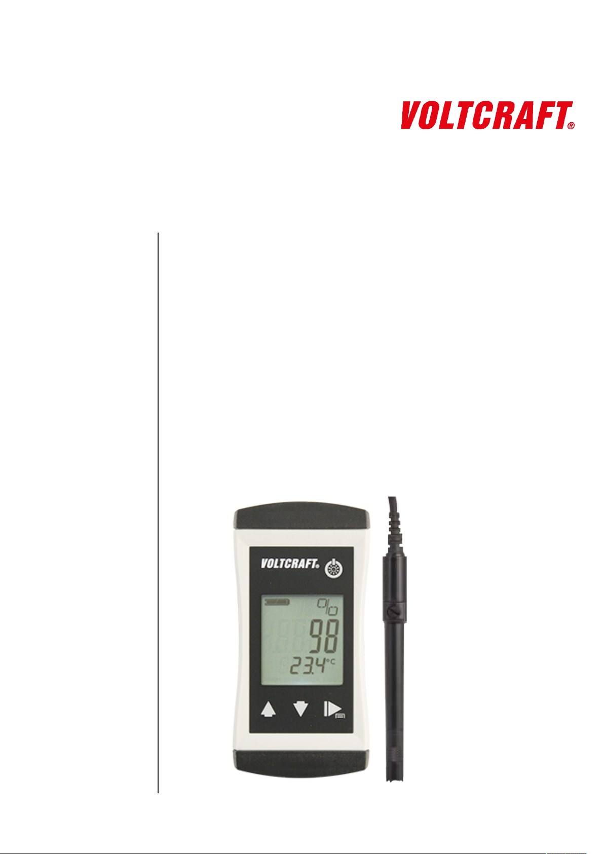
DO-400
Oxygen measuring device
Permanently connected oxygen sensor
Waterproof

Table of contents
Table of contents
1 Legal address of the manufacturer................................................................................................... 4
2 About this documentation ................................................................................................................. 5
2.1 Foreword............................................................................................................................................... 5
2.2 Purpose of the document...................................................................................................................... 5
2.3 Correctness of content.......................................................................................................................... 5
2.4 Layout of this document........................................................................................................................ 5
2.5 Further information ............................................................................................................................... 6
3 Safety ................................................................................................................................................... 7
3.1 Explanation of safety symbols .............................................................................................................. 7
3.2 Foreseeable misuse ............................................................................................................................. 7
3.3 Safety instructions ................................................................................................................................ 8
3.4 Intended use ......................................................................................................................................... 9
3.5 Qualified personnel............................................................................................................................... 9
4 Description ........................................................................................................................................ 10
4.1 Scope of delivery ................................................................................................................................ 10
4.2 Job description.................................................................................................................................... 10
5 The product at a glance ................................................................................................................... 11
5.1 The DO-400 / -410.............................................................................................................................. 11
5.2 Display elements ................................................................................................................................ 11
5.3 Operating elements ............................................................................................................................ 11
6 Bases for measurement ................................................................................................................... 13
6.1 Oxygen sensor.................................................................................................................................... 13
6.1.1 Explanation ......................................................................................................................................... 13
6.1.2 Design................................................................................................................................................. 14
6.1.3 Service life .......................................................................................................................................... 14
6.1.4 Operating position............................................................................................................................... 15
6.1.5 Measurement accuracy ...................................................................................................................... 15
6.1.6 Residue............................................................................................................................................... 15
6.2 Instructions for oxygen measurement................................................................................................. 15
6.2.1 Salinity correction ............................................................................................................................... 15
6.2.2 Environmental pressure, water depth and air pressure ...................................................................... 16
6.3 Commissioning, filling and maintenance of the sensor....................................................................... 16
7 Maintenance ...................................................................................................................................... 18
7.1 Operating and maintenance notices ................................................................................................... 18
7.2 Battery ................................................................................................................................................ 18
7.2.1 Battery indicator.................................................................................................................................. 18
7.2.2 Changing battery ................................................................................................................................ 18
7.3 Calibration and adjustment ................................................................................................................. 19
7.3.1 Automatic calibration in the air............................................................................................................ 19
8 Operation........................................................................................................................................... 21
8.1 Commissioning ................................................................................................................................... 21
8.1.1 Explanation ......................................................................................................................................... 21
8.2 Configuration ...................................................................................................................................... 21
8.2.1 Explanation ......................................................................................................................................... 21
2 / 29 B-H86.0.21.DB214-1.0

Table of contents
8.2.2 Opening the configuration menu......................................................................................................... 21
8.2.3 Configuring parameters of the configuration menu............................................................................. 22
8.2.4 Adjustment of the measuring input ..................................................................................................... 23
8.2.5 Configuring parameters of the adjustment menu................................................................................ 24
9 Error and system messages............................................................................................................ 26
10 Disposal............................................................................................................................................. 27
11 Technical data................................................................................................................................... 28
12 Service ............................................................................................................................................... 29
12.1 Manufacturer....................................................................................................................................... 29
B-H86.0.21.DB214-1.0 3 / 29

1 | Legal address of the manufacturer DO-400
1 Legal address of the manufacturer
Conrad Electronic SE
Klaus-Conrad-Str. 1
D-92240 Hirschau
http://www.conrad.com
WEEE reg. no. DE 28001718
4 / 29 B-H86.0.21.DB214-1.0

DO-400 About this documentation | 2
2 About this documentation
2.1 Foreword
Read this document carefully and familiarise yourself with the operation of the product
before you use it. Keep this document ready to hand and in the immediate vicinity of
the product so that it is available to the personnel/user for reference at all times in
case of doubt.
The product was developed according to the state of the art and fulfils the requirements of the applicable European and national Directives. All corresponding documents are available from the manufacturer.
Only technically qualified persons are permitted to carry out commissioning, operation,
maintenance and decommissioning. The qualified personnel must have carefully read
and understood the operating manual before beginning any work.
2.2 Purpose of the document
– This document describes the operation and maintenance of the product.
– Provides important information for working safely and efficiently with the product.
– In addition to the quick reference guide with all relevant legal and safety content in
hard copy, this document is a detailed reference option for the product.
2.3 Correctness of content
The contents of this document were checked for corrected and are subject to a continuous correction and updating process. This does not rule out potential errors. In the
event that errors are discovered or in case of suggestions for improvement, please inform us immediately via the indicated contact information in order to help us make this
document even more user-friendly.
2.4 Layout of this document
Description
Each chapter is explained at the beginning in the description.
Prerequisite
All mandatory prerequisites are then listed for each step.
Instruction
Tasks to be carried out by the personnel / user are represented as numbered instructions. Adhere to the sequence of the specified instructions.
Representation
Shows an illustrative instruction or a configuration of the product.
Formula
Some instructions include a formula for a general understanding of a configuration,
programming or a setting of the product.
B-H86.0.21.DB214-1.0 5 / 29

2 | About this documentation DO-400
Outcome of an action
Result, consequence or effect of an instruction.
Emphases
In order to simplify legibility and provide a clearer overview, various sections / information are emphasised.
– 1234 Display elements
– Mechanical controls
– Product functions
– Product labels
– Cross-reference [}p.5]
– Foot notes
2.5 Further information
Software version of the product:
– V1.2 or later
For the exact product name, refer to the type plate on the rear side of the product.
NOTE
For information about the software version, press and hold the ON button to switch on
the product for longer than 5 seconds. The series is shown in the main display and the
software version of the product is shown in the secondary display.
6 / 29 B-H86.0.21.DB214-1.0
DO-400 Safety | 3
3 Safety
3.1 Explanation of safety symbols
DANGER
This symbol warns of imminent danger which can result in death, severe bodily injury,
or severe property damage in case of non-observance.
DANGER
This symbol indicates danger for living tissue as well as a variety of materials, which
can be damaged or destroyed when coming into contact with this chemical. Caustic
effect, protective equipment required!
DANGER
This symbol indicates danger for all life forms, which can result in death or acute or
chromic damage to the health after inhaling, swallowing or absorbing this chemical
through the skin.
CAUTION
This symbol warns of potential dangers or harmful situations which can cause damage
to the device or to the environment in case of non-observance.
NOTE
This symbol indicates processes which can have a direct influence on operation or
can trigger an unforeseen reaction in case of non-observance.
NOTE
This symbol instructs the use of eye protection which protects the eyes from harmful
influences when working with powerful light, UV radiation, laser, chemicals, dust,
splinters or weather influences.
NOTE
This symbol instructs the use of protective gloves which offer protection from mechanical, thermal, chemical, biological or electrical hazards.
3.2 Foreseeable misuse
The fault-free function and operational safety of the product can only be guaranteed if
generally applicable safety precautions and the device-specific safety instructions for
this document are observed.
If these notices are disregarded, personal injury or death, as well as property damage
can occur.
B-H86.0.21.DB214-1.0 7 / 29
3 | Safety DO-400
DANGER
Incorrect area of application!
In order to prevent erratic behaviour of the product, personal injury or property damage, the product must be used exclusively as described in the chapter Description
[}p.10] in the operating manual.
– Do not use in safety / Emergency Stop devices!
– The product is not suitable for use in explosion-prone areas!
– The product must not be used for diagnostic or other medical purposes on pa-
tients!
– The product is not intended to come into direct contact with food. For measure-
ment in foods, samples must be taken and discarded after the measurement!
3.3 Safety instructions
This product has been designed and tested according to the safety requirements for
electronic measuring devices.
DANGER
Potassium hydroxide!
The electrode contains potassium hydroxide. This causes burns. All contact with the
skin, clothing and eyes should be avoided. Nevertheless, should contact occur, take
the following measures.
– Eyes: Flush with flowing water for at least 15 minutes, seek medical attention!
– Skin: Wash with large amounts of water for several minutes!
– Clothing: Remove immediately!
– If swallowed: Drink large amounts of water, do not induce vomiting and seek med-
ical attention!
CAUTION
Erratic behaviour!
On suspicion that the product can no longer be operated without danger, it must be
decommissioned and prevented from recommissioning with appropriate labelling. The
safety of the user can be impaired by the device if, for example, if it shows visible
damage, it no longer works as specified or if it was stored for an extended period of
time under unsuitable conditions.
– Visual inspection!
– In case of doubt, send the product to the manufacturer for repair or maintenance!
NOTE
If the product is stored at a temperature above 50 °C, or is not used for an extended
period of time, the batteries must be removed. Leaks from the batteries are avoided as
a result.
NOTE
This product does not belong in children's hands!
8 / 29 B-H86.0.21.DB214-1.0

DO-400 Safety | 3
For this purpose, also refer to
2 Technical data [}28]
3.4 Intended use
The product is designed for analysis of the oxygen concentration and/or oxygen saturation in freshwater and salt water. It is used, for example, for the monitoring of wells,
sewer lines and aquaria. A minimum flow to the sensor of approx. 30 cm/sec is necessary for a correct measurement.
See Technical data [}p.28].
3.5 Qualified personnel
For commissioning, operation and maintenance, the relevant personnel must have adequate knowledge of the measuring process and use of the measurements, for which
purpose this document makes a valuable contribution. The instructions in this document must be understood, observed and followed.
In order to ensure that no risks arise from the interpretation of the measurements in
the concrete application, the user must have additional technical knowledge, because
the user is liable in case of damage/danger due to misinterpretation as a result of inadequate technical knowledge.
B-H86.0.21.DB214-1.0 9 / 29

4 | Description DO-400
4 Description
4.1 Scope of delivery
Please check to ensure the completeness of the product after opening the package.
You should find the following components:
– Quick reference guide
– Handheld measuring device, ready for operation, including batteries
– Permanently connected oxygen sensor
4.2 Job description
The product offers precision, speed and reliability in a compact, ergonomic housing.
Additional impressive features include the dust-proof and waterproof design in accordance with IP 65/67 and the 3-line illuminated display, which offers overhead display at
the push of a button. The product can be switched on, switched off and configured and
the measurements and parameters can be adjusted and held with the operating elements. The product with maintenance-friendly galvanised O2 sensor is an entry-level
device suitable for everyday use. Concentrations in mg/l or ppm and saturation in percentage can be read directly without using tables. Calibration with environmental air
takes place at the push of a button. Use of a GSKA protective cap is recommended for
field use in bodies of water in order to protect the membrane.
10 / 29 B-H86.0.21.DB214-1.0

DO-400 The product at a glance | 5
5 The product at a glance
5.1 The DO-400 / -410
LCD Display DO-400 / -410 DO-400 / -410
5.2 Display elements
Display
Battery indicator Evaluation of the battery status
Unit display Display of units, if applicable, with unstable symbol
or type of mode, min/max/hold
Main display Measurement of the current O2 value or value for
Auxiliary display Corresponding temperature for the displayed O
Bar graph Progress for calibration and visualisation of the
NOTE
The unit display shows a rotating circle segment in the first position as long as the
measurement is unstable, if the position is unoccupied by the unit display.
5.3 Operating elements
On / Off button
Press briefly Switch on the product
Long press Switch off the product
min/max/hold
2
value with unit.
electrode evaluation
Activate / deactivate lighting
Reject changes in a menu
B-H86.0.21.DB214-1.0 11 / 29

5 | The product at a glance DO-400
Up / Down button
Press briefly Display of the min/max value
Change value of the selected parameter
Long press Reset the min/max value of the current measure-
ment
Both simultaneously Rotate display, overhead display
Function key
Press briefly Freeze measurement
Return to measurement display
Call up next parameter
Long press, 2s
Start menu configuration, (ONF appears in the display
Long press, 4s
Start automatic calibration, (AL appears in the display
12 / 29 B-H86.0.21.DB214-1.0
DO-400 Bases for measurement | 6
6 Bases for measurement
6.1 Oxygen sensor
6.1.1 Explanation
The oxygen sensor is an active sensor. It consists of a platinum cathode, a lead anode
and potassium hydroxide (KOH) as an electrolyte. If oxygen is present, it is reduced
on the platinum cathode and the sensor delivers a signal. If no oxygen is present, no
signal is delivered. The anode is consumed by the oxygen measurement. The sensor
ages. Furthermore, the sensor loses water through the permeable membrane, in particular, when it is stored in dry air. Therefore, it should be checked and maintained
regularly and replaced as necessary.
DANGER
Potassium hydroxide!
The electrode contains potassium hydroxide. This causes burns. All contact with the
skin, clothing and eyes should be avoided. Nevertheless, should contact occur, take
the following measures.
– Eyes: Flush with flowing water for at least 15 minutes, seek medical attention!
– Skin: Wash with large amounts of water for several minutes!
– Clothing: Remove immediately!
– If swallowed: Drink large amounts of water, do not induce vomiting and seek med-
ical attention!
NOTE
Protective goggles must be worn for all of the following activities!
NOTE
Protective gloves must be worn for all of the following activities!
NOTE
Always store the oxygen sensor damp. It should always be stored in a storage bottle
filled with water or in a container filled with water. After storage for an extended period,
any potential deposit layers, such as algae, must be cleaned off of the membrane with
a soft paper towel prior to measurement.
B-H86.0.21.DB214-1.0 13 / 29

6 | Bases for measurement DO-400
Storage bottle
Shaft
Membrane head
Refill opening
Platinum electrode
6.1.2 Design
Platinum electrode
Storage bottle
Membrane head
Refill opening
If oxygen is present, it is reduced on the platinum electrode and the sensor delivers a
signal. Soiling on the platinum electrode or between the membrane and electrode can
influence the measurement.
The storage bottle is provided to keep the membrane moist. The service life of the
sensor is extended as a result. Distilled or deionised water is in the storage bottle; do
not add any other liquids!
The membrane head is covered with a thin plastic membrane. Faulty measurements
will occur if the membrane is damaged or there are large air bubbles or even an air
bubble ring on the membrane. This can also be the cause if a sensor can no longer be
calibrated. The GWOK 02 membrane head is a spare part and can be re-ordered separately.
Electrolyte must be filled or added for the initial commissioning of a sensor which is
delivered dry, when performing maintenance or after use at high temperatures.
6.1.3 Service life
The sensor signal deteriorates relatively quickly at the end of the service life of the
sensors. The electrode evaluation in %, therefore, can only be used as a guide value.
A value of 70% does not mean that exactly 70% of the service life is still available,
rather that the electrode signal has 70% of a comparison signal.
NOTE
The sensor evaluation is updated by the measuring device after a successfully performed calibration of the oxygen sensor.
The nominal service life can be reduced significantly due to use. Influential factors include:
– Storage / operating temperature
14 / 29 B-H86.0.21.DB214-1.0
– Contamination of the measured water

DO-400 Bases for measurement | 6
– Mechanical stress of the sensor membrane
– Storage in dry air
– Continuous use in elevated carbon dioxide concentrations
6.1.4 Operating position
The oxygen sensor should be arranged vertically upwards with the connecting cable.
A slight angle of inclination does not impair the measurement.
6.1.5 Measurement accuracy
The measurement accuracy can be impaired by:
– An inadequate flow below the necessary value of approx. 30cm/sec.
– The water temperature and sensor temperature must be the same. The most ac-
curate measurements are provided when the measuring temperature is calibrated.
6.1.6 Residue
Visible residue collecting as a reaction product in the interior of the membrane cap on
the lead-oxide lead anode is red or brown from reaction with oxygen and lead carbonate and is white from reaction with carbon dioxide. These substances can collect on
the membrane, but do not normally impair the measuring function and can be mostly
removed in the course of maintenance of the sensor. Prior to screwing on the membrane cap, they should be removed as far as possible in order to prevent particles
from being trapped between the membrane and the platinum cup. A rapid or excessive formation of lead carbonate after commissioning is an indication of air in the
sensor. This is usually due to incomplete filling or a leak due to improper fitting of the
cap / fill screw or membrane leak.
6.2 Instructions for oxygen measurement
The following must be observed when measuring dissolved oxygen:
– The storage bottle must be removed before the measurement.
– The sensor must have been calibrated.
– The sensor and the liquid to be measured must have the same temperature. The
temperatures of the two must match.
– The sensor must be immersed at least 3 cm into the liquid to be measured.
– A flow speed of at least approx. 30 cm/sec is necessary for exact measurements.
Either stir continuously or use an appropriate stirring device
– The measurement is sensitive to jarring! Therefore, make sure that the container
is not struck with the sensor while stirring, because this can significantly impair the
measured value.
– The oxygen partial pressure, oxygen concentration in mg/l and oxygen saturation
in % are calculated from the sensor signal and temperature. In accordance with
DIN38408-C22, the measurement is relative to water-vapour-saturated air.
6.2.1 Salinity correction
With increasing salinity SAL, which is the value for the salt content in the water, the solubility of oxygen in water decreases, i.e. with the same oxygen partial pressure, fewer
mg of oxygen are dissolved per litre of water. To determine this oxygen concentration,
therefore, the salinity of the medium must be entered first; see Configuring parameters
of the configuration menu [}p.22]. A salinity correction is not necessary in freshwa-
B-H86.0.21.DB214-1.0 15 / 29

6 | Bases for measurement DO-400
ter; the value is 0. A salinity of approx. 35 PSU is normal for sea water. The salinity
correction is adjusted to aqueous media having a chemical composition corresponding
to sea water. The International Oceanographic Tables (IOT) are used as a basis for
the correction.
6.2.2 Environmental pressure, water depth and air pressure
The environmental pressure, water depth and air pressure play an important role at
the place of measurement for the following points:
– Calculation of oxygen saturation in % SAT. Clean water can achieve 100 % satura-
tion in air. There must be no oxygen-depleting processes, such as biological decaying processes, chemical effects or oxygen enhancing processes, such as excessive ventilation or photosynthesis. This could result in an oversaturation above
100%.
– Calculation of the oxygen concentration in mg/l
– The valuation of calibration
Adjusting the pressure parameter on the product is recommended prior to calibration.
In the scope of measuring accuracy, specifying the current air pressure in the region
based on meteorological data or the standard pressure based on sea level is sufficient.
For example:
0 m above NN: 1013 hPa
300 m above NN: 978 hPa
600 m above NN: 943 hPa
1000m above NN: 899 hPa
Description
Prerequisite
Instruction
6.3 Commissioning, filling and maintenance of the sensor
The sensor is delivered dry. Therefore, the sensor is well-suited for storage. The
sensor must be filled in good time before the measurement. A wait time of approx. 2
hours after filling should be planned in order to allow the sensor to stabilise. Commissioning with initial filling, filling and maintenance of the sensor are explained in the following chapter.
– Protective goggles
– Protective gloves
– A suitable screwdriver
– Pipette
– Household towel
– KOH electrolyte
– A spare GWOK 02 membrane head, if applicable
1. Unscrew the membrane head.
2. Unscrew the seal screw from the refill opening.
NOTE
If the sensor was already filled and deposits have formed, it should be cleaned with
KOH via the fill opening or removed. Loose residue can be rinsed out in the process.
The platinum cup on the front of the membrane must be clean. Remove any soiling or
electrolyte solution with a paper towel.
16 / 29 B-H86.0.21.DB214-1.0

Outcome of an action
DO-400 Bases for measurement | 6
3. Fill the pipette with the KOH electrolyte and initially fill the membrane head to ¾
full. Rinse off the excess electrolyte.
4. Slowly fill the sensor via the fill opening. In the process, tilt the sensor from side to
side and tap the shaft to force out air bubbles. The sensor holds approximately 5
ml. If air bubbles no longer appear and the refill opening is filled up to the rim with
KOH, screw the in the seal screw again.
5. Rinse off excess KOH and screw the sensor on with the membrane head. In the
process, if there are any recognisable air bubbles under the membrane, KOH
must be added.
6. After filling, the sensor should rest for 2 hours before a calibration is started.
The sensor has now been refilled. A sensor evaluation during the calibration should
produce a result of 100%.
NOTE
Should it no longer be possible to calibrate the sensor or it only delivers unstable
measurements, it must be maintained and/or the membrane head must be replaced
B-H86.0.21.DB214-1.0 17 / 29
7 | Maintenance DO-400
7 Maintenance
7.1 Operating and maintenance notices
NOTE
If the product is stored at a temperature above 50 °C, or is not used for an extended
period of time, the batteries must be removed. Leaks from the batteries are avoided as
a result.
NOTE
The electrode should be stored in dry rooms at a temperature between 10 °C and 30
°C. If the storage temperature range is exceeded or undercut, the electrode can be
destroyed. It should always be stored wet in distilled or deionised water.
7.2 Battery
7.2.1 Battery indicator
If the empty frame in the battery display blinks, the batteries are depleted and must be
replaced. However, the device will still operate for a certain length of time.
If the BAT display text appears in the main display, the battery voltage is no longer adequate for operation of the product. Now the battery is fully depleted.
7.2.2 Changing battery
DANGER
Danger of explosion!
Using damaged or unsuitable batteries can generate heat, which can cause the batteries to crack and possibly explode!
– Only use high-quality and suitable alkaline batteries!
CAUTION
Damage!
If the batteries have different charge levels, leaks and thus damage to the product can
occur.
– Use new, high-quality batteries!
– Do not use different types of batteries!
– Remove depleted batteries and dispose of them at a suitable collection point!
NOTE
Unnecessary screwing places the water-tightness of the product, among other things,
at risk and should be avoided.
18 / 29 B-H86.0.21.DB214-1.0

DO-400 Maintenance | 7
NOTE
Read the following handling instructions before replacing batteries and follow them
step by step. If disregarded, the product could be damaged or the protection from
moisture could be diminished.
Description
Prerequisites
Instruction
Outcome of an action
Proceed as follows to replace the batteries.
– The product is switched off.
1. Unscrews the Phillips screws and remove the cover.
2. Carefully replace the two Mignon AA batteries. Ensure that the polarity is correct!
It must be possible to insert the batteries in the correct position without using
force.
3. The O-ring must be undamaged, clean and positioned at the intended depth. In order to facilitate assembly and avoid damage, a suitable grease can be applied.
4. Fit the cover on evenly. The O-ring must remain at the intended depth!
5. Tighten the Phillips screws.
The product is now ready for use again.
7.3 Calibration and adjustment
Description
Prerequisite
Instruction
7.3.1 Automatic calibration in the air
The following steps describe how to calibrate the product automatically.
– The product is switched on.
NOTE
Calibration takes place in air saturated with water vapour. The GCAL 3610 calibration
container or the storage bottle can be used for this purpose. The membrane of the
electrode must be dry for the calibration. Prior to performing the calibration of the
membrane, dab away water droplets from the membrane with a soft, dry cloth. The following must be observed when using the storage bottle:
Only insert the electrode far enough into the storage bottle that the membrane does
not come into contact with the water in the bottle.
Unscrew the lid of the storage bottle and only position it so that a small exchange of
air and pressure equalisation can take place
1. Place the electrode in the calibration container. If necessary, wait until the temperature has equalised and a stable value has been achieved.
2. Press the Function key for 4 seconds to open the Calibration menu. The display
shows (AL.
3. Release the Function key.
4. The product determines the correct value automatically.
B-H86.0.21.DB214-1.0 19 / 29

7 | Maintenance DO-400
Outcome of an action
After successful completion of the calibration the assessment of the electrode condition is displayed briefly in percent. An aged or contaminated electrode, incorrect adjustment of the pressure, contamination of the platinum electrode or a damaged membrane can be the cause for a lower evaluation.
If the calibration is not completed successfully an error message is displayed. (AL ERR.
appears in the display See Error and system messages [}p.26]. Confirm the error
message pressing the Function key. The product restarts and the value of the last successful calibration is restored.
20 / 29 B-H86.0.21.DB214-1.0
8.1.1 Explanation
Description
Prerequisite
Instruction
Outcome of an action
DO-400 Operation | 8
8 Operation
8.1 Commissioning
The product is switched on with the On/Off button. It may be necessary to configure
the product after switching on. See Configuration [}p.21].
– Sufficiently full batteries are inserted in the product.
– Press On/Off button.
Information about the configuration of the product appears in the display.
POFF
T.OF
T.SL
SAL
The product is now ready for measurement.
Automatic shutoff
Zero point correction
Gradient correction
Salinity correction Links when the salinity correction is active
NOTE
The product must be calibrated to the electrode prior to starting the measurement.
See Calibration and adjustment service.
8.2 Configuration
8.2.1 Explanation
The following steps describe how to adapt the product for your purposes.
Automatic shut-off activated. The product is
switched off if no buttons have been pressed after
the adjusted time
If a zero point correction of the temperature sensor
was made
If a gradient correction of the temperature sensor
was made
NOTE
There are various configuration parameters available depending on the product version and configuration. They can differ depending on the product version and configuration.
8.2.2 Opening the configuration menu
Description
Prerequisite
Instruction
B-H86.0.21.DB214-1.0 21 / 29
In order to configure the product, you must first open the Configuration menu. The
menu is opened as shown in the illustration.
– The product is switched on.
1. Press the Function key for 2 seconds to open the Configuration menu.
2. (ONF appears in the display. Release the function key.
3. By briefly pressing the Function key, you can scroll through the parameters. Select
the parameter you would like to configure.

8 | Operation DO-400
4. When you have selected the desired parameter, change the parameter to the desired value with the Up button and the Down button.
5. The changes are saved after running through the entire Configuration menu. STOR
appears in the display. The Configuration menu can be exited from any arbitrary
parameter by pressing and holding the Function key for 2 seconds. The changes
made up that point are saved.
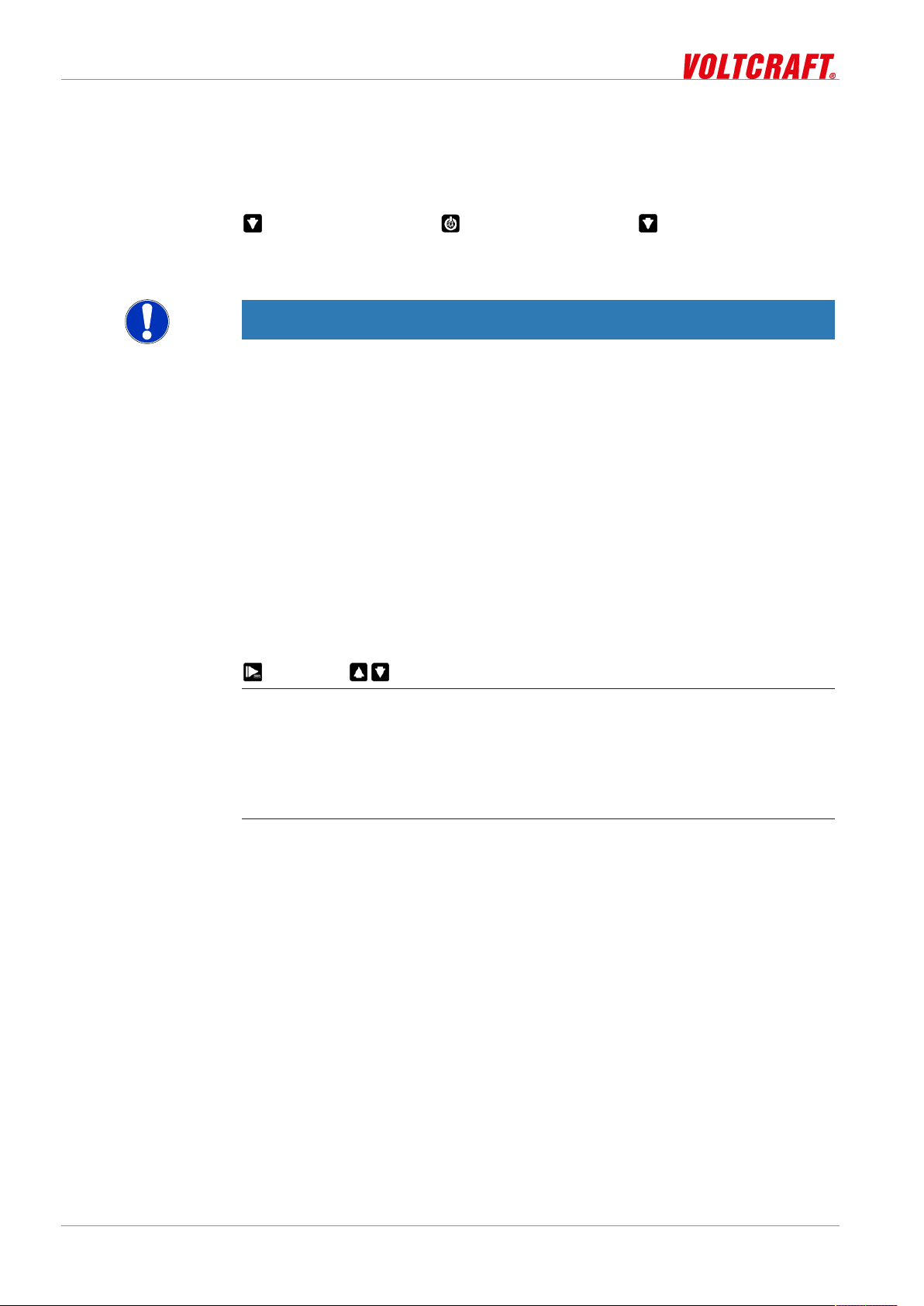
Representation
Outcome of an action
Call up menu Next parameter Change value Save changes Discard
2s Press: Single
step
Hold: Rapid
change
The Configuration menu is closed after the last parameter.
NOTE
If the product is switched off without saving the configuration, the last save value is reproduced on the next start-up of the product.
changes
2s 2s
Description
Prerequisite
Instruction
Representation
8.2.3 Configuring parameters of the configuration menu
The following representation shows the available parameters and various configuration options.
– The Configuration menu is open. See Opening the configuration menu [}p.21].
1. Select the desired parameter you would like to configure.
2. Adjust the desired configuration in the selected parameter with the Up button and
Down button.
3. The available configuration options are listed for each parameter in the following
representation.
Parameter Values Meaning
Input
INP
SAT %
(ONC mg/l
(ONC ppm
Pressure
Oxygen saturation in per cent
Oxygen concentration in mg/l
Oxygen concentration in ppm
SET.P
500 .. 4000
Salinity correction
SAL
0 .. 70
22 / 29 B-H86.0.21.DB214-1.0
Environmental pressure in hPa, corresponding to
mbar
Salinity in the measuring medium in PSU, corresponding to g/kg

Shut-off time
POFF
Backlighting
L,TE
Temperature unit
UN,T
OFF
15 30 60 120 240
OFF
15 30 60 120 240
ON
°(
°F
DO-400 Operation | 8
No automatic shut-off
Automatic shut-off after a selected time in minutes,
during which no buttons have been pressed
Backlighting deactivated
Automatic shut-off of the backlighting after a selected time in seconds, during which no buttons have
been pressed
No automatic shut-off of the backlighting
Temperature display in °C
Temperature display in °F
Outcome of an action
8.2.4 Adjustment of the measuring input
Description
Prerequisites
Instruction
Factory settings
IN,T
NO
YES Reset product to factory settings. IN,T DONE appears
The changed value is saved and the Configuration menu is closed. STOR appears in
the display. If necessary, the product is restarted automatically in order to adopt the
changed values.
Use current configuration
in the display
NOTE
The configuration is closed if no button is pressed for 2 minutes. Any changes made
up to that point are not saved. C.END appears in the display.
The temperature input can be adjusted with the zero point correction and the gradient
correction. If an adjustment is made, you change the pre-adjusted factory settings.
This is signalled with the T.OF or T.SL when the product is switched on. The standard
settings of the zero point value and the gradient value is 0.00. It signals that no correc-
tion is made.
In order to adjust the product, you must first open the Adjustment menu. The menu is
opened as shown in the illustration.
– Sufficiently full batteries are inserted in the product.
– The product is switched off.
1. Press and hold the Down button.
2. Press the On/Off button to switch on the product and open the Configuration
menu. Release the Down button. The display shows the first parameter.
3. By briefly pressing the Function key, you can scroll through the parameters. Select
the parameter you would like to configure.
B-H86.0.21.DB214-1.0 23 / 29
8 | Operation DO-400
4. When you have selected the desired parameter, change the parameter to the desired value with the Up button and the Down button.
5. In order to save the new parameter value, press and hold the Function key for
longer than 1 second.
Representation
Call up menu
Hold Release
Outcome of an action
The Configuration menu is closed after the last parameter.
NOTE
If the product is switched off without saving the configuration, the last save value is reproduced on the next start-up of the product.
8.2.5 Configuring parameters of the adjustment menu
Description
Prerequisites
Instruction
Representation
The following representation shows the available parameters and various configuration options.
The Adjustment menu is open. See Adjustment of the measuring input [}p.23].
1. Select the desired parameter you would like to configure.
2. Adjust the desired configuration in the selected parameter with the Up button and
Down button.
3. The available configuration options are listed for each parameter in the following
representation.
Parameter Values Meaning
Formula
Example calculation
Zero point correction
T.OF
0.00
-5.00 .. 5.00
No zero point correction
Zero point correction in °C. and/or at °F -9.00 ..
9.00
Gradient correction of the temperature
T.SL
0.00
-5.00 .. 5.00
No gradient correction
Gradient correction in %
Zero point correction:
Displayed value = measured value – T.OF
Gradient correction °C:
Display = (measured value – T.OF) * (1 + T.SL / 100)
Gradient correction °F:
Display = (measured value – 32 °F – T.OF) * (1 + T.SL / 100) + 32 °F
– Zero point correction T.OF to 0.00
– Gradient correction T.SL to 0.00
– Display unit UNIT to °C
– Display in ice water -0.2 °C
24 / 29 B-H86.0.21.DB214-1.0

Outcome of an action
DO-400 Operation | 8
– Display in ice water setpoint T.OF = 0.0 °C
– Display in water bath 36.6 °C
– Display in water bath setpoint T.SL = 37.0 °C
– T.OF = display zero point correction – setpoint zero point
– T.OF = -0.2 °C – 0.0 °C = -0.2 °C
– T.SL = (setpoint gradient correction / (display gradient correction – T.OF) – 1) *100
– T.SL = (37.0 °C / (36.6 °C – (-0.2)) -1) *100 = 0.54
The changed value is saved and the Configuration menu is closed.
NOTE
If the product is switched off without saving the configuration, the last save value is reproduced on the next start-up of the product.
B-H86.0.21.DB214-1.0 25 / 29

9 | Error and system messages DO-400
9 Error and system messages
Display Meaning Possible causes Remedy
No display,
unclear characters or no
response
when buttons are
pressed
BAT
BAT LO
(AL ERR.2
(AL ERR.3
(AL ERR.4
(AL ERR.5
ERR.1
ERR.2
SYS ERR
Battery depleted
System error
Product is defective
Battery depleted Battery depleted Replace battery
Battery depleted Battery depleted Replace battery
Slope is too low
Incorrect oxygen reference
Slope is too high
Incorrect oxygen reference
Incorrect calibration
temperature
Time exceeded during automatic calibration
Measuring range exceeded
Measuring range is
undercut
System error Error in the product Switch product on/off
Battery depleted
Error in the product
Product is defective
Electrode contaminated or defective
Electrode contaminated or defective
Temperature too low
or too high
Unstable electrode
signal
Contaminated electrode
Temperature not
equalised
Measurement too
high
Electrode or product
defect
Faulty calibration
Measurement too
low
Electrode or product
defect
Replace battery
Send in for repair
Perform calibration in damp
environmental air
Maintain the electrode
Perform calibration in damp
environmental air
Maintain the electrode
Range of 5..40 °C
Use calibration container
Maintain the electrode
Restart calibration
The measurement is above
the permissible range
Check electrode
Perform calibration
Send in for repair
Check electrode
Send in for repair
Replace batteries
Send in for repair
26 / 29 B-H86.0.21.DB214-1.0

10 Disposal
NOTE
The device must not be disposed of with household waste. If the product is disposed
of, please take it to a municipal collection point, where it will be transported to a disposal company in accordance with requirements of hazardous goods laws. Otherwise,
return it to us, freight prepaid. We will then arrange for the proper and environmentally-friendly disposal. Please dispose of empty batteries at the collection points intended for this purpose.
DO-400 Disposal | 10
B-H86.0.21.DB214-1.0 27 / 29
11 | Technical data DO-400
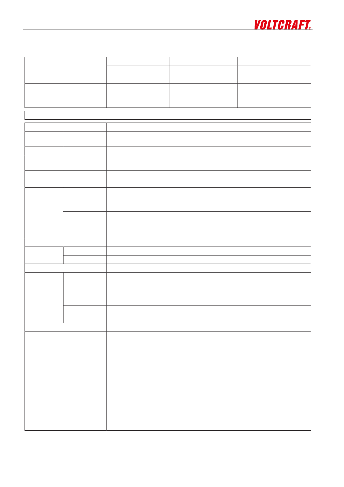
11 Technical data
Measuring range O2 concentration O2 saturation Temperature
0.0 .. 20.0 mg/l
0.0 .. 20.0 ppm
Accuracy (at nominal temperature)
Temperature compensation 0 .. 50 °C (or 32 .. 122 °F)
Nominal temperature 25°C
Measuring
cycle
Connections Permanently connected oxygen sensor
Display 3-line segment LCD, additional symbols, illuminated (adjustable white, perman-
Additional functions Min/Max/Hold
O2 calibration Automatic calibration in the air
Housing Break-proof ABS housing
Protection rating
Dimensions
L*W*H [mm]
and weight
Connections Permanently connected oxygen sensor
Operating
conditions
Storage temperature 0 .. 40 °C
Current supply
Auto-power-OFF function The device switches off automatically if this is activated
Directives and standards The devices conform to the following Directives of the Council for the harmon-
Device -20 to 50 °C; 0 to 95 % r.h. (temporarily 100 % r.h.)
Electrode 0 .. 40 °C
Current requirement/
battery life
Battery indicator
±1.5 % of measured
value
± 0.2 mg/l
approx. 2 measurements per second
ent illumination)
IP65 / IP67
108 * 54 * 28 mm without electrode
130 g, incl. battery, without electrode
190 g, incl. battery and electrode
2*AA battery (included in the scope of delivery)
approx. 0.8 mA, approx. 2.7 mA with lighting
Service life > 3000 hours with alkaline batteries (without backlighting)
4-stage battery status indicator,
Replacement indicator for depleted batteries: "BAT"
isation of legal regulations of the Member States:
2014/30/EU EMC Directive
2011/65/EU RoHS
Applied harmonised standards:
EN 61326-1:2013 Emission limits: Class B
Immunity according to Table 2
Additional errors: < 0.5 % FS
EN 50581:2012
0 .. 200 % 0 .. 50 °C
32 .. 122 °F
±1.5 % of measured
value
± 0.2 %
± 0.3 °C
The device is intended for mobile use and/or stationary operation in the scope
of the specified operating conditions without further limitations.
28 / 29 B-H86.0.21.DB214-1.0

Contact
DO-400 Service | 12
12 Service
12.1 Manufacturer
If you have any questions, please do not hesitate to contact us:
VOLTCRAFT
Distributed by
Conrad Electronic SE
Klaus-Conrad-Str. 1
92240 Hirschau, Germany
Tel.: +49 9604 40 87 87
Fax: +49 180 5 312110
kundenservice@conrad.de
WEEE reg. no. DE 28001718
B-H86.0.21.DB214-1.0 29 / 29
 Loading...