

Page 1
Assembly Instructions
MODELS:
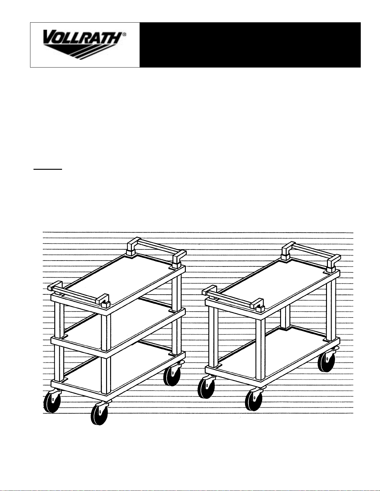
97101 — 2 Shelf KD Plastic Cart
97102 — 3 Shelf KD Plastic Cart
OWNER’S MANUAL
KD PLASTIC CARTS
and Parts List
Form No. 21814 Rev. B 1/04
Page 2
OWNER’S MANUAL
ASSEMBLY INSTRUCTIONS
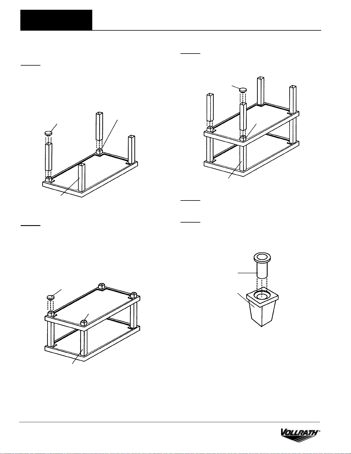
STEP 1
Lay shelf on flat surface (smooth side up). Insert a support
tube over each projection as shown. Place the hammer block
into a support tube and with a rubber mallet, pound down
gently until support tube bottoms out against shelf. Do this
on all four (4) corners.
KD Plastic Cart
STEP 3
Insert second group of support tubes over each projection of
second shelf — refer to Step 1.
Hammer Block
Hammer Block
Corner Projection
ASSEMBLY INSTRUCTIONS
Top of Shelf
is Viewed
Support Tube
STEP 2
Position second shelf (smooth side up) on the above
assembly, making sure that the four (4) corner projections
underside of second shelf insert into each support tube.
Place hammer block on top of corner projections of second
shelf, and with a rubber mallet, pound down gently until
shelf bottoms out against support tube. Do this on all four
(4) corners.
Corner
Projection
Top of Shelf
is Viewed
Support Tube
STEP 4
Position third shelf — refer to Step 2.
STEP 5
Insert socket into caster plug as shown.. User hammer block
and rubber mallet to drive socket all the way in.
Socket (Metal)
Hammer Block
Caster Plug
Corner
Projection
.
Top of Shelf
is Viewed
Support Tube
Form No. 21814 Rev. B 1/04 Page 2
Page 3

KD Plastic Cart
STEP 6
Flip cart over. Insert caster plug into each corner projection.
Place hammer block over caster plug and with a rubber
mallet, pound down gently, making sure that the caster plug
bottoms out against corner projection, insuring that the part
is in securely.
Caster Plug
Bottom of Shelf
Corner Projection
is Viewed
STEP 7
Insert the stem of the caster all the way into the caster plug.
Do this on all four (4) corners.
Caster
OWNER’S MANUAL
STEP 8
Flip cart over as shown. Insert a handle tube into one (1)
handle support, right side and one (1) handle support, left
side. Place assembly into the corner projections of the top
shelf as shown. At the same time press down on both handle
supports insuring that the part is in securely. (Repeat for
other side).
Leg of
Handle
Support
Support
Tube
Handle Support
Right Side
Handle Tube
Corner Projection
Handle
Support Left
Side
ASSEMBLY INSTRRUCTIONS
Stem of Caster
Caster Plug
Stem of
Caster
Support
Tube
Corner Projection
Caster
Corner Projection
Bottom of Shelf
is Viewed
NOTE: The direction of the leg of the handle support is
pointing away from the cart.
Bottom of Shelf
is Viewed
Page 3 Form No. 21814 Rev. B 1/04
Page 4

OWNER’S MANUAL
EXPLODED VIEW — 3 SHELF CART
ASSEMBLY INSTRUCTIONS
KD Plastic Cart
EXPLODED VIEW — 2 SHELF CART
Replacement Parts List
Ref. No. Part. No. Description
1 21961 Handle Support, Left Side
2 21816 Handle Tube
3 21561 Plastic Shelf 18″ x 31″
4 21817 Support Tube 12″ (model 97102 only)
5 21860 Support Tube 24½″ (model 97101 only)
6 21962 Caster Plug (plastic)
7 21815 Socket (metal)
8 21800 Caster 4″ Diameter
9 21960 Handle Support, Right Side
--Not Shown--
10 21963 Hammer Block
The Vollrath Company, L.L.C.
1236 North 18
th
Street
Sheboygan, WI 53082-0611
U.S.A.
Main Tel: 800.624.2051
Service Tel: 800.628.0832
Fax: 800.752.5620
Vollrath of Canada, Ltd.
6320 Danville Road, Unit 1
Mississauga, Ontario L5T 2L7
Canada
Tel: 905.565.1167
Tel: 800.695.8560
FAX: 905.565.1168
Form No. 21814 Rev. B 1/04 Page 4
 Loading...